1
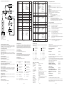
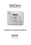
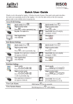
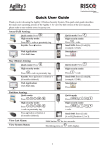
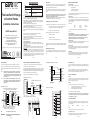
IMPOR TANT!
Input:
Nominal Temp Range:
The GardTec370 Range
of Control Panels
Installation Instructions
AC230V +/-10% ~50Hz 125mA Max. 35W Max
0 - 50°C
Gardtec 370 Range Metal Versions
For Indoor Use Only
Gardtec 370 Range Plastic Versions
For Indoor Use Only
This equipment is intended only for use as a Security Alarm Control Panel. Adequate
ventilation away from heat and humidity must be provided. The unit must be fixed
securely to a non-flammable surface using suitable fixings.
All mains wiring must be to BS7671 (1992) IEEE wiring regulations (or appropriate
international regulatory standards). See Mains Supply Connection section within this
manual for more detailed instructions.
All wiring must be protected from sharp or jagged edges.
All Low voltage (alarm) wiring must be to the appropriate international regulatory
standards and comply to good wiring practice.
Replacement fuses should be of the same type and rating conforming to IEC 127.
The maximum current draw from the unit for all output combinations must not exceed
1Amp.
RISCO Group UK Ltd
RISCO Group UK Ltd reserve the right to amend the software and features without prior notice
Output Terminal Descriptions
The Gardtec 370 Control Panel is a seven zone microprocessor based unit that has
been designed to be suitable for domestic and small commercial installations. All
zones are fully programmable by the engineer.
Speaker Terminals
This pair of terminals provide connection for:-
It should be noted that if a new four digit engineer code starts with a 9 it will be
locked into the system and may only be changed by using the code again
(default to factory settings will have no effect).
We recommend that this engineer manual and the user manual are read and fully
understood before any installation of the system is carried out.
ProDigi Communicator (Standard, AV & AV Serial)
Up to four remote keypads may be fitted to the GARDTEC 370 control panel.
It is possible to use a ProDigi Communicator with a Gardtec 370 Metal version.
Connection details for the ProDigi are shown below.
PGM Options
All RKP models have an EOL jumper with the exception of the 370
model which is supplied with an EOL resistor. If only one RKP is
used the jumper or resistor should be fitted in that RKP. If more than
one RKP is used the jumper or resistor should only be fitted to the
last RKP in the line.
When using RKPs fitted with an Entry/Exit zone only one may be
used irrespective of the number of RKPs fitted. This RKP zone will
be Entry/Exit with Chime allocated and will be indicated on the
display as ‘r1’.
Fig2. ProDigi Connection
Note: ProDigi EOL jumper must be OFF
ProDigi 580
581 SEL jumper must be ON
RKP 2 etc.
TMP+
The Position of the underside flap retaining screw.
The Panel should be fixed to the wall using appropriate wall plugs and No.8 screws at
least 30mm long. Do not tighten the screws at this stage, wait until all your wiring is in
place.
Mains Supply Connection
A 230V a.c supply should be taken directly from the consumer unit. In order to comply with the requirements of B.S 4737 this should be via a 3 Amp unswitched fused
spur.
D OUT
BELL+
As power is applied all segments of the twin seven segment display will be lit for
approx six seconds. During this period press 4 6 YES NO to ensure that the Control
Panel is at factory settings. The display will then show set or unset.
0V
BELLHOLD-
Reset to Default Modes
S-
BELL-
+12V
STROBE-
Gardtec 370
OUT IN
+
TAMP
-
+
+
+
+
N/C Devices
SAB TAMP
-
N/O Device
N/C Devices
N/C Devices
N/O Device
IMPORTANT:
ACE RX should be configured as 581.
Ensure only 1 keypad has a EOL jumper or
resistor fitted.
Page 4
16 Ohm
Min
Supply for Detectors
RKPs Etc
Note:
Programmable terminal for
latching detectors etc.
N/C Devices
Speaker
12V Trig
Strobe
Light
N/O Device
0V
Tamp
Ret
N/C Devices
N/O Device
Sounder/SAB Unit
AZ1
-
+
AZ2
Method 2
Apply power to the panel and press 00 within the first 5 seconds.
-
Page 6
Down power the panel again and leave for at least 10 seconds.
Re-apply either the mains or battery supply.
Press 4 6 YES NO within the first 5 seconds.
The Control Panel is now back to factory defaults.
Note: The two methods shown above will have no effect on the engineer code if
it started with a '9'. If this is the case, only re-use of the programmed engineer
code will allow it to be changed.
System Programming
+
AZ3
+
AZ4
-
The system may be programmed by the engineer by use of the engineer code (1234
factory default). Other Engineer/User functions are also available to the engineer,
these are as follows.
AZ5
Set
Chime
+
Note: Details of the above functions are given in the User Manual.
+
-
AZ6
Unset
Remove
Test
Log
-
+
N/C Devices
N/O Device
Page 5
+
-
N/O Device
Note: EOL jumper should be fitted only to last RKP in chain.
Note: If 370 RKP is used 680 ohm resistor should be
fitted between 12v & D IN terminals on last RKP
Method 1
To gain temporary access to the factory default settings remove the link marked LK2
R/S on the P.C.B (this will give temporary access to the default codes 5678 for user
and 1234 for engineer). See note below.
1)
2)
3)
Fig5. Input Connections
N/C Tamper Switches
D OUT
SAB TMP
F TMP
N/O Device
Fig3. Control Panel Output Connections
AUX 12V
-
D IN
Initial Power Up
When the Control Panel is powered up it will be either set or unset dependent on the
state of the Control Panel when it was powered down. The factory default state will be
unset.
N/C Devices
BELL HOLD-
D IN
Bell Terminals
This pair of terminals are the output for the Bell or external sounder. The negative
terminal is switched during an alarm period. A maximum of 1 Amp may be drawn
from these terminals (see power supply rating above).
Page 3
R TMP
N/C Tamper
BELL
0V
D OUT
-
0V
D OUT
-
STROBE
12V
0V
D IN
-
E/E+
0V
D IN
SPKR
E/E+
Strobe Terminals
This pair of terminals are the output for the Strobe. The negative terminal is switched
during an alarm period. A maximum of 1 Amp may be drawn from these terminals
(see power supply rating above).
Page 2
AUX 12V
12V
PGM1
E/E-
DATA
TMP+
E/E-
N/C E/E Zone
+
TMP+
12V
370 type
RKP only
RKP 1
OUT IN
RKP 2
AUX 12V Terminals
This pair of terminals supply the + and - supply for the keypads and detectors. 1 Amp
is available from these terminals (see power supply rating above).
+
12V
Note: Terminal position will differ dependant on RKP model used.
Some models may also have dual terminal markings.
Pulse Off
Exit / Entry
Power Supply Rating
It should be noted that the Gardtec 370 has 1 Amp available for the full system.
Sounders, detectors and other auxiliary items should be included when
calculating current drawn by the system. Any damage caused through overloading the Control Panel will not be covered by the warranty.
Readability of the display.
Novagard 1E
E/E+
Fig1. RKP Connection
Switch +ve
Strobe
Int Alarm
A more detailed description is given in the programmable options description
(page 12).
The fixing of a 3 amp unswitched fused spur.
ST-
ProDigi
Communicator
E/E-
-
Note:
Please refer to the ProDigi Installation manual for more details.
AUX 12V
Note:
Pulse On
Bell
Test
Access for the routing of cables for the system from detection devices,
sounders (internal and external), remote keypads, mains, etc.
Fig4. Typical Novagard 1E Connections
The ProDigi must be programmed via a Gardtec 800 Series control panel or a ProDigi
Programmer. When programming the ProDigi the EOL jumper should be ON and the
581 SEL jumper OFF. When you have finished programming the EOL jumper should
be taken OFF and the 581 SEL jumper should be put ON.
A speaker is supplied in each keypad. If any additional speakers are fitted they should
present a minimum impedance of 16 Ohm.
Consideration in locating the fixing position of the Control Panel should be given to:
DATA
A four core connection will be required between the control panel data port and
remote keypad(s), all keypads must be in a 'daisy chain' format as shown in Fig2.
below.
Any Extension Speaker(s)
Planning the Control Panel Location
PR5032Rev1.2
Remote Keypads
Optional 32 Ohm Panel Speaker
PGM 1 Terminal
This terminal provides the switch +ve (or set +ve) required by most types of latching
detectors. The terminal is an open collector output held at 12V through an integral 1k
resistor. Max current sink into this terminal is 50mA. This terminal is programmable for
other uses if required.
Operation of the keypad.
All documentation and manuals must be thoroughly read by suitably qualified
installation personnel prior to installation.
The unit has no user serviceable parts inside. Internal access should only be by suitably qualified personnel.
Gardtec 370 Metal Versions
The unit must be Earthed. It is the responsibility of the installation engineer to
ensure that the earth connection to the unit lid is good on completion of the installation
or after service.
Gardtec 370 Plastic Versions
Provision is provided for an earth connection within the mains input connector block,
this connection is for protection of the wiring only and is not functional for the unit.
Battery Fuse
An in-line Battery Fuse has now been incorporated into this product. The fuse rating
is 2 Amp Anti-Surge. The fuse holder is spring loaded, therefore you should ensure
that the battery lead is not under tension in order to maintain a good connection
between the fuse and the holder.To change the fuse, push the two halves of the holder
together and twist anti-clockwise. Please ensure correct battery charge on completion
of the installation and during each service visit.
Page 1
Keypad Speaker(s)
Upon completion of the installation the engineer may, if required, re-program several
factory set options so as to tailor the Control Panel to suit the requirements of the
system.
When fitting the RKP(s) consideration should be given to:
The unit is intended for use with a suitable re-chargeable lead acid battery
permanently connected to the appropriate terminals.
Tel: 0161 655 5500 Fax: 0161 655 5501
Int Tel: +44 161 655 5500 Fax: +44 161 655 5501
Internet: www.riscogroup.com
e-mail: [email protected]
Technical Support Tel: 0161 655 5600
Technical Support Fax: 0161 655 5610
(Mon - Fri 08:30-1730)
Introduction
AZ7
-
Program Engineer Code
Programming of the Engineer Code is only possible via the Engineer Code (e.g
1234). See Engineer Programming Flow Chart (overleaf).
Page 7
Fig5. Engineer Programming Flow Chart
MENU
No
1
System is Unset
Enter Engineer Code
Press 0 (Quit)
Press
Do you wish to use
Engineer Mode
NO
Press YES
Press NO
Press 0 (Quit)
This is Engineer Mode
Enter Option Number Then YES
Press NO
This is the
Existing Setting
FUNCTION
OPTIONS AVAILABLE
Zone1 Attributes LEFT DIGIT
0=12Hr
1=E/E
2=Access
3=Panic
4=24Hr
5=Fire
6=Alert
7=Exit Term
8=Part E/E
RIGHT DIGIT
0=Full Set
1=Part1
2=Part2
3=Part1&2
4=Full Set+Chime
5=Part1+Chime
6=Part2+Chime
7=Part 1&2+Chime
Zone 2 Attributes
As Zone1 Options
80
3
Zone 3 Attributes
As Zone1 Options
00
4
Zone 4 Attributes
As Zone1 Options
01
5
Zone 5 Attributes
As Zone1 Options
02
6
Zone 6 Attributes
As Zone1 Options
00
7
Zone 7 Attributes
As Zone 1 Options
30
8
Sounder Level
CHIME
LEFT DIGIT
ENTRY/EXIT
RIGHT DIGIT
0-9
Press NO
Enter new
Setting Here
55
00 - 99seconds
30
10
Part Set Exit Time
00 - 99seconds
30
Setting Modes
FULL SET
LEFT DIGIT
PART SET
RIGHT DIGIT
0=Exit Term
1=E/E Door
2=Time
3=Time+E/E
0=Exit Term
1=E/E Door
2=Time
3=Time+E/E
This section will give a description of the programmable options that are available on
the GARDTEC 370 Control Panel. For more details of the parameters available for
each option please refer to the section Programming Charts.
Zone 1-7 Attributes (Option No.1-7)
This option allows the zone type, zone part set remove and zone chime features to
be programmed for zone 1-7.
Sounder Level (Option No.8)
This option allows for the fine adjustment of the speaker volume for Entry/Exit tone
and Chime to be programmed. Coarse adjustment is via the potentiometer situated to
the edge of the PCB.
Full Set Exit Time (Option No.9)
Allows the Exit Time for full set to be programmed.
Entry Time 1
00 - 99seconds
30
14
Entry Time 2
00 - 99seconds
10
15
Keypad
Bell Re-Arms
00 Re-Arms - 99 Re-Arms
99
17
Bell Ring Time
00 minutes - 99 minutes
20
18
Bell Delay ‡
00 minutes - 99 minutes
00
19
Bell Mode
20
PA Mode ‡
21
Reset Modes
TAMPER RING
RIGHT DIGIT
0=Off
1=On
00
00=Audible PA
10=Silent PA
00
RESET MODE
RIGHT DIGIT
0=Any Code
1=Master Code
2=Anti-Code
3=Engineer Code
01
Service Timer
99 = Off
99
00weeks - 98weeks.
Page 10
Reset Modes (Option No.21)
The reset modes are programmed using this function.
Service Timer (Option No.22)
The service timer period is programmed using this function. When service time
expires the system will lock the user out. Extra service may be gained using the
Anti-Code software. If the timer is set to 99 weeks the timer function is Off.
Display Messages
'1 to 7'
Represent zones 1 to 7
'E
't'
Tamper zone
'CA'
'S
'
System Full Set
'S
'
System Part 1 Set
'S
'
System Part 2 Set
'S
'
System Part 3 Set
' o1 '
Unset User 1
' o2 '
Unset User 2
' o3 '
Unset User 3
' o4 '
Unset User 4
' o5 '
Unset User 5
' o6 '
Unset User 6
' o7 '
Unset User 7
' o8 '
Unset User 8
' o9 '
Unset User 9
' o0 '
Unset User 0 (Engineer)
Alarm has occurred
' rE '
Watchdog reset
' AL '
' 1 to 7 ' (flashing)
'E
'
System Part 1 Setting
'E
'E
'
System Part 3 Setting
Un'
'
Alert keys activated
'
System Part 2 Setting
System is Unset
'
System Fully Set
'
'
System Part 1 Set
'
'
System Part 2 Set
'
'
System Part 3 Set
'AL '
An Alarm has occurred
'Ac'
Anti-Code reset required
Keypad (Option No.15)
Key numbers 1 & 3 when pressed together may be programmed using this function to
give a particular response.
'Fb'
Fuse Fail or Battery Fault
'Ct'
RKP Tamper
'bb'
Bell box Tamper
'Pc'
Mains Power Cut
Bell Re-Arms (Option No.16)
This option is used to program the number of times the Bell will Re-Arm during a set
period.
'Cb'
Control Box Tamper
'r1'
Keypad Zone
'PL'
Phone Line or Digi Fault
Bell Ring Time (Option No.17)
This option is used to program the Bell ring time.
'En'
Engineer Reset required (or Service Timer activated).
Page 13
Resetting After an Alarm
Four reset modes are available after an alarm. These are as follows.
Any Code
The system will reset the next time Any Code is used to set the system.
Master Code
The system will only reset if the Master Code or Engineer code is used to set the
system.
Engineer Code
The system will only reset if the Engineer Code is used to set the system.
Anti-Code
The system may only be reset by use of an Anti-Code.
The engineer code may be used to override the Anti-Code Reset.
To Reset System:1)
Enter Code of correct type (see above).
2)
Proceed to set the system.
3)
If a set is not required re-enter the code to abort setting.
To Reset by Anti-Code:1)
Make a note of the Code given by the display.
2)
Using the Gardiner Technology Anti-Code software on a P.C or an
Anti-Code Generator enter the four digit source code given by the Panel.
3)
Enter the resulting four digit Anti-Code into the Control Panel.
Zone Type Terminology
Zone 1 to 7 was removed when system was set.
12 Hour
Zone active when Control Panel is Set
Access
Will allow to pass through on Exit.
Will allow to pass through on entry only if entry/exit is opened first
24 Hour
Internal sounder if Unset. Full alarm if Set.
Entry/Exit
Zone used as last exit point or first entry point.
Part E/E
As Access if Control Panel is Full Set
As entry/exit if Control Panel is Part Set
P.A
24 Hour Personal Attack. Active if Control Panel is Set or Unset
Alert
Internal sounder only. Recorded to Log
Fire
Will give Fire alarm when activated (pulsed external sounders) with
panel set or unset.
Exit Terminator With Panel programmed to set with exit terminator the panel
will only set when zone is activated during exit.
Page 11
Other Accessories
A complete range of accessories are available to complement your Gardtec 370
security system. Some of this range is shown below:-
Gardtec 370 Speaker Kit
(01-087)
A 32 Ohm speaker.
Rear Tamper
(02-064)
The Gardtec Speech Dialler
(04-069)
The Gardtec Speech Dialler offers communications between your security system
and any telephone or selected pagers.
One Common message along with three Information messages may be programmed
to be sent to up to four telephone numbers. The unit offers a full range of programmable features to ensure your message gets across.
System Full Setting
'
Page 12
BELL TYPE
LEFT DIGIT
0=SAB
1=SCB
Display Messages (Log)
Apart from the System and Status displays the following messages may also appear
whilst viewing the Log.
Setting Modes (Option No.11)
Allows the setting modes for Full and Part-set to be programmed.
Entry Time 2 (Option No.14)
Allows Entry Time 2 to be programmed.
10
RIGHT DIGIT
Always 0
Bell Mode (Option No.19)
The Bell Mode Function allows the mode of the Bell to be programmed from SAB to
SCB. In SAB mode the current for the sounder is supplied from the Control Panel
unless the cable to the Bell box is cut. In SCB mode the current for the sounder is
supplied by the sounder battery under all circumstances. The Bell Tamper mode if
programmed ON will always trigger the external sounder from the control panel in the
event of a Bell Tamper.
The Following System messages are possible.
Entry Time 1 (Option No.13)
Entry time may be looked at as three events. Entry time 1 will give the normal Entry
tone. Entry time 2 will give a louder warning tone. After both times have expired the
external sounders will sound. This option allows Entry Time 1 to be programmed.
ALERT KEYS 1&3
LEFT DIGIT
0=Off
1=Panic
2=Fire
3=Alert
16
22
Part Set Exit Time (Option No.10)
Allows the Exit Time for Part set to be programmed.
Part-set Sounders & Output 1 Mode (Option No.12)
Allows the Part-set exit sounder mode and the operating mode of the programmable
output 1 terminal to be programmed.
31
13
Page 9
Page 8
DEFAULT
PROGRAMMABLE
OUTPUT1 PGM1
RIGHT DIGIT
0=Pulse On
1=SW+
2=Pulse Off
3=Bell
4=Strobe
5=Entry/Exit
6=Test
7=Int. Alarm
LEFT DIGIT
Always 0
‡ Gardtec 370 Metal
Programmable Options Description
Part Set Sounders PART
& Output 1 Mode SOUNDERS
LEFT DIGIT
0=All Parts silent
1=Part 2 silent
2=Parts1&3 silent
3=All Parts
Audible
22
Enter New Value Then Press YES
Press YES
Enter new Engineer Code
Press YES
Re-Enter Engineer Code
Press YES
Press 0 to return to Unset
OPTIONS AVAILABLE
0-9
Full Set Exit Time
11
FUNCTION
The terminology used for the various zone types are explained in this section.
9
Press NO
MENU
No
12
14
2
Press NO
Press NO
DEFAULT
Gardtec 370 Specification
Power Input
Max Loop Resistance
Loop Delay Time
Fuses
Mains
Aux
Low Voltage Output
Power Supply Rating
Battery Sizes
Construction
Complies with
Number of Zones
Display Type
User Code Default
Engineer Code Default
Event Log Size
No. of User Codes
No. of Part Sets
230V a.c +/- 10% @50Hz
2K Ohm
300 milliseconds
ProDigi Communicator
ProDigi AV Communicator
ProDigi AV Serial Communicator
(04-073)
(04-072)
(04-071)
Additional RKPs
125mA Anti Surge
1A Quick Blow
13.8V (typical) Regulated
1A
Metal Version 12V 1.2Ah, 2.0Ah, 3.0Ah, 7.0Ah
Plastic Version 12V 1.2Ah, 2.0Ah
Metal Version 1.2mm Mild Steel
Plastic Version 3mm Polycarbonate
B.S 4737
7 + Tamper (+RKP E/E Zone on 580 style RKPs)
2 x 7 segment LED(except ACE RX)
5678
1234
80
9
3
Page 14
Gardtec 370 LED RKP
Gardtec 370/580 LED RKP
Gardtec 370/580 Contour LED RKP
Gardtec 370/580 Profile LED RKP
ACE RX
ACE TX (Key Fob)
(01-144)
(01-113)*
(01-147)*
(01-114)*
(01-136)
(01-130)
*Include RKP Zone
Up to four RKPs may be fitted to the Gardtec 370 Control Panel.
ACE offers Setting, Unsetting, Part Setting & Resetting via high security Infra-Red
keyfobs. ACE is available as compact stand alone units which are fully compatible
with the Gardtec 370 Control Panel.
Page 15