1
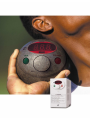
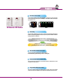
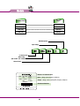
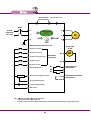
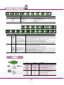
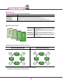
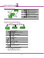
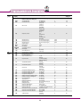
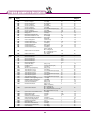
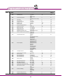
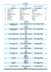
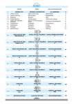
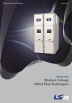
Variable Frequency Drive / Inverter
iC5
0.4-2.2kW 1 phase 200-230Volts
“ Global standard iC5,
serves a wide variety of applications
to meet the majority of user needs. ”
� Modbus communication (Option)
� PID control
� Sensorless vector control
� Motor parameter auto tuning
Models
05
04
Features
Wiring
07
06
Specifications
Keypad
08
08
Terminal configuration
Program parameters descriptions
11
09
Program Parameters
Tips on Installation
18
16
Checking & Troubleshooting
“ Compact iC5,
is the best for a small and cost
effective configuration”
Features
Sensorless vector control
The iC5 adopts sensorless vector control algorithm, and it improves not only the torque
control characteristics, but the speed controlability in an uncertain condition caused by the
load variation as well.
LS Inverter iC5 Series
Auto tuning
The auto tuning algorithm in the iC5 sets the motor factors automatically that brings the
traditional commissioning difficulties mainly in low speed by the load variation and the low
torque generation to a settlement.
� Difficulty of measuring the motor constant � Input errors by an user
� Low torque in low speed � Low speed by the load variation � Setup by an expert
characteristic
�
� Setup by an user � Improving torque in low speed
� Auto tuning of the motor characteristics � Optimized motor control
PNP and NPN switchable dual signals
The iC5 provides PNP and NPN signals for outside controllers.
It works with 24Vdc regardless of the type of PLC or control signals.
Communication interface, ModBus-RTU
The iC5 provides the most popular communication interface, ModBus-RTU for remote
control by PLC or other devices.
Programmable PID process control
PID process control is used in iC5 to make speed corrections quickly with a minimal
amount of overshoot and oscillation for the control of flow, temperature, pressure and etc.
04
Models
Applicable motor
220V, single
phase
0.4kW (0.5HP)
SV004iC5-1
0.75kW (1HP)
SV008iC5-1
1.5kW (2HP)
SV015iC5-1
2.2kW (3HP)
SV022iC5-1
EMI filter optional
Input voltage
LS Starvert drive
Motor rating
(004 : 0.4kW ~ 022 : 2.2kW)
Name of Series
Model no. of LS Starvert drive
INPUT
200 ~ 230V
5.5A
1phase
50/60Hz
OUTPUT
0 ~ INPUT V
3phase
2.5A
0.1~400Hz
0.5HP/0.4kW
Input : voltage, current, frequency and phase
Output : voltage, current, capacity(FLA), frequency and phase
Barcode and Serial no.
05
Specifications
� Specifications (200-230V class)
Model
Motor rating
[HP]
[kW]
Capacity[kVA]
FLA[A]
Voltage
Frequency
Voltage
Frequency
Output ratings
Input ratings
SV004iC5-1
0.5
0.4
0.95
2.5
SV008iC5-1
SV015iC5-1
1
2
0.75
1.5
1.9
3
5
8
Three phase, 200 to 230V
0 to 400Hz
Single phase, 200 to 230V ( ±10% )
50 to 60Hz ( ±5% )
SV022iC5-1
3
2.2
4.5
12
� Control
Control method
Frequency setting resolution
Frequency setting accuracy
V/F ratio
Overload capacity
Torque boost
V/F control, Sensorless vector control
∙Digital reference : 0.01Hz
∙Analog reference : 0.06Hz/60Hz
∙Digital : 0.01% of Maximum output frequency ∙Analog : 0.1% of Maximum output frequency
Linear, Squar pattern, User V/F
1min. at 150%, 30sec. at 200% ( with inverse characteristic )
Manual( 0 to 15% adjustable ), Auto
� Operation
Input signal
Operator control
Frequency setting
Start signal
Multi-step
Multi-step accel
/decel time
Output signal
Emergency stop
Jog
Fault reset
Operation status &
Fault output
Indicator
Operation
function
Keypad / Terminal / Communications
∙Analog : 0~10V/4~20mA
∙Digital : Keypad
∙Communication : RS485
Forward / Reverse
Setting up to 8 speeds ( use multi-function terminal )
0.1~6000 sec. Max. 8 types available by multi-function terminal
Selectable accel/decel patterns : Linear, U and S
Interrupting the output of the drive
Jog operation
Reset the fault when protective function is active
Frequency detection, Overload alarm, Stalling, Overvoltage, Undervoltage,
Drive overheating, Run, Stop, Constant speed, Speed searching,
Fault output ( Relay and Open collector output )
Choose one from output frequency, current, voltage and DC voltage.(Output voltage : 0~10V )
DC braking, Frequency limit, Frequency jump, Second function,
Slip compensation, Reversing prevention, Auto restart, PID control
� Protection functions
Drive trip
Drive alarm
Momentary
power less
Overvoltage, Undervoltage, Overcurrent, Drive overtemperature, Motor overtemperature, I/O phase loss, I/O mis-wiring,
Overload , External device fault 1.2, Loss of speed command, Hardware fault, Communication error, CPU error
Stall prevention, Overload alarm
∙Less than 15 msec : keeping operation
∙More than 15 msec : auto restart available
� Display keypad
Operation information
Trip information
Output frequency, current and voltage, Set frequency value, Operation speed, DC voltage
Display the trip cause when the protection function activates. Recent 5 faults records stored
� Environment
Operating ambient temp.
Storage temperature
Humidity
Altitude & Vibration
Atmosphere
Pressure
-10℃ ~ 50℃
-20℃ ~ 65℃
90%Rh max.(non condensing)
1000m max, 5.9m/sec2(0.6g) max.
No corrosive gas, flammable gas, oil mist or dust
70~106k Pa
06
Wiring
short-circuit link
(* reserved for DC reactor)
P1
P
N
MCCB
AC input
Single phase
200 ~ 230V
L1
U
L2
V
G
W
IM
KNOB
Ground
Multi-function input terminals, P1 to P5
Analog output
(0~10V)
P1 (factory set : Forward)
P2 (factory set : Reverse)
AM
P3 (factory set : Emergency stop)
AM
Multi-function
Input terminal
P4 (factory set : RST)
CM
P5 (factory set : JOG)
P24
Multi-function relay
output terminal
30A
PNP DC24V output
30B
30C
VR
Power for speed signal (12V 10mA)
MO
Multi-function open collector
output terminal
EXTG
VI
I
Speed signal input (0~10V)
Speed signal input (4~20mA)
CM
Common
Note : 1.●= Main circuit terminal ○ = Control circuit terminal
2. Analog output voltage is adjustable upto 12V.
3. Speed command can be set by Voltage, Current, Voltage+Current, Keypad, Keypad knob+Voltage , and Keypad knob+current.
07
Terminal configuration
L1
L2
P
Terminal
L1, L2
U, V, W
P, P1
G
30A
30B
Terminal
Input
Output
P1, P2
P3, P4, P5
P24
VR
VI
I
CM
AM-CM
P1
N
U
Signal
AC line input
Drive output
DC reactor
Ground
30C
V
W
G
Description
Single phase AC line input
3 phase output terminals to motor
Connecting DC reactor
Chassis ground
P4
P5
VR
V1
CM
I
AM
MO
EXTG
P24
P1
P2
CM
P3
Signal
Multi-function input
PNP DC24V output
Frequency setting power
Frequency setting(Voltage)
Frequency setting(Current)
Common
For monitoring
330A, 30C Multi-function relay and
30B
Open collector output
MO-EXTG Terminal
Description
Used for multi-function input. Factory default settings are as follows. P1 = FX, Forward
P2 = RX, Reverse P3 = BX, Emergency stop P4=RST, Fault reset P5=JOG, Jog Operation Command
DC24V power supply in case of PNP mode
Power for Analog frequency setting, Maximum output is +12V 10mA
Input DC 0 to 10V to set frequency. Input resistance is 20kΩ
Input DC 4 to 20mA to set frequency. Input resistance is 250Ω
Common terminal for the analog frequency setting signal and the FM(for monitoring)
Output one out of Output frequency, Output current, Output voltage and DC voltage.
Factory default set is to Output frequency.
Maximum output voltage = 0 to 12V, output current = 10mA
To interrupt the output when the protection function activates
or output multi-function signal.
Multi-function relay terminal : Max. AC250V/1A, DC30V/1A
Open collector output terminal : Max. DC24V 50mA
Keypad
Key
RUN
STOP/RESET
●
Function
Run key
Stop/Reset key
Program/Enter
Frequency
Selection
Up
Down
Left
Right
KNOB(Volume)
NPN/PNP
▲
▼
◀
▶
08
Description
To operate the drive
To stop operating or reset in case of fault
To change parameters and save them
To change the frequency
Mode selection between NPN and PNP
To increase the parameter values
To decrease the parameter values
To move the cursor left
To move the cursor right
Program parameters
� Parameter group
There are 4 parameter groups to set parameters properly for the operation.
Group
Drive group
Function 1 group
Function 2 group
Input/Output group
Description
Basic parameters such as Command frequency, Accel/Decel time, etc.
Basic functional parameters such as Max. frequency, Torque boost, etc.
Application parameters such as Frequency jump, Max./Min. of limit of frequency, etc.
Parameters to construct the sequence such as Multi-function terminal setting, Auto operation, etc.
� Parameter group navigation
Drive group
DRV Gr.
FU1 Gr.
FU2 Gr.
I/O Gr.
Basic operation parameters such as Command frequency,
Accel/Decel time, etc.
Function 1 group
Basic functional parameters for adjusting Output frequency,
Voltage, etc.
Function 2 group
Application parameters of PID operation, The 2nd motor
setting, etc.
Input/Output group Parameters to construct the sequence such as Multi-function
terminal setting, etc
● Shifting between groups is possible only in the first code of each group.
◀)
Shift by using Left shift key (◀
▶)
Shift by using Right shift key (▶
(1)
(1)
(1) The value of the Command frequency will be displayed in the first code of the Drive group.
It will show the value set by the operator. The factory set value is 0.0.
09
Program parameters
� Parameter navigation in Drive group
1
2
3
4
5
� Procedure to set command frequency in Drive group
To input new command frequency 30.05[Hz] from 0.0 set in the factory
1
2
3
∙The first code “0.0” displayed.
∙Press pro/ent(●
●) key.
∙The digit of the first decimal place can be changed.
∙Press right (▶
▶) key.
∙The digit of the second decimal place can be changed.
∙Press up(▲
▲) key until the digit becomes 5.
4
∙Press left(◀
◀) key.
5
∙The left digit can be set.
∙Press left(◀
◀) key.
6
∙Press left(◀
◀) key.
7
8
9
∙Though 00.0 is displayed, the actual value remains at 0.05.
∙Make 3 by pressing up(▲
▲) key.
∙Press pro/ent(●
●) key.
∙30.0 is flickering.
∙Press pro/ent(●
●) key to stop the flickering.
∙Command frequency 30.0 is stored.
Note : (1) The LCD on the keypad of Drive iC5 displays only 3 digits.
◀ ▶) to monitor and set the parameters.
Use the shift keys (◀
(2) To cancel the parameter setting press the shift keys
◀ or ▶) while 30.0 is flickering in the procedure no. 8 .
(◀
10
∙The first code “0.0” displayed.
∙Press up(▲
▲) key once to move to next code.
∙The second code “ACC” appears.
∙Press up(▲
▲) key once to move to next code.
∙The third code “dEC” is shown.
∙Press up(▲
▲) key to move to next code.
∙To move to the last code press up(▲
▲) key until “drC”
appears.
∙Press up(▲
▲) key once more to return to the first code.
∙To move in reverse order use down(▼
▼) key.
Program parameters descriptions
Drive
group
Keypad
display
0.00
ACC
DEC
Output frequency : during run
Reference frequency : during stop
Acceleration time
Deceleration time
Drv
Drive mode
Frq
Frequency mode
St1
St2
St3
Cur
RPM
DCL
v0L/P0r/t0r
n0n
FU1
group
Description
Step frequency 1
Step frequency 2
Step frequency 3
Output current
Motor speed
DC voltage
User display selection
Fault display
drC
Motor direction set
FU1
FU2
I/O
F0
Function Group 1 selection
Function Group 2 selection
I/O Group selection
Jump to desired code #
F3
Run prevention
F5
Acceleration pattern
F6
Deceleration pattern
F7
Stop mode
F8
F9
F10
F11
F12
F13
F14
F20
F21
F22
F23
F24
F25
F26
F27
F28
F29
DC injection braking frequency
DC injection braking ON-delay
DC injection braking voltage
DC injection braking time
Starting DC injection braking voltage
Starting DC injection braking time
Motor exciting time
Jog frequency
Maximum frequency
Base frequency
Starting frequency
Frequency limit selection
Frequency limit - high
Frequency limit - low
Manual/Auto torque boost selection
Torque boost in forward direction
Torque boost in reverse direction
F30
Volts/Hz pattern
Setting range
Factory default
Adjustable
during run
0 to Max. frequency[Hz]
0.00
Yes
0 to 6000 [sec]
0 to 6000 [sec]
0(Keypad)
1(Fx/Rx-1)
2(Fx/Rx-2)
3(ModBus)
0(Keypad-1)
1(Keypad-2)
2(Volume)
3(V1)
4(I)
5(Volume+1)
6(V1+I)
7(Volume+V1)
8(ModBus)
0 to Max. frequency[Hz]
0 to Max. frequency[Hz]
0 to Max. frequency[Hz]
*[A]
*[rpm]
*[V]
*
*
F(Forward)
R(Reverse)
5
10
Yes
Yes
1
No
0
No
10.00
20.00
30.00
*
*
*
*
*
Yes
Yes
Yes
*
*
*
*
*
F
Yes
*
*
*
1
Yes
Yes
Yes
Yes
0
No
0
No
0
No
0
No
5
0.1
50
1
50
0
1
10
60
60
0.5
0
60
0.5
0
5
5
No
No
No
No
No
No
No
No
No
No
No
No
No
No
No
No
No
0
No
1 to 60
0(None)
1(Forward disable)
2(Reverse disable)
0(Linear)
1(S-curve)
0(Linear)
1(S-curve)
0(Decel)
1(Dc-brake)
2(Free-run)
F23 to 60[Hz]
0 to 60 [sec]
0 to 200[%]
0 to 60 [sec]
0 to 200[%]
0 to 60 [sec]
0 to 60 [sec]
0 to 400 [Hz]
40 to 400 [Hz]
30 to Max. frequency[Hz]
0 to 10 [Hz]
0(No), 1(Yes)
0 to High limit [Hz]
Low limit to Max. frequency[Hz]
0(Manual), 1(Auto)
0.0 to 15.0[%]
0.0 to 15.0[%]
0(Linear)
1(Square)
2(User V/F)
11
Program parameters descriptions
FU1
group
FU2
group
Keypad
display
Description
Setting range
Factory default
Adjustable
during run
F31
F32
F33
F34
F35
F36
F37
F38
F39
F40
F50
F51
F52
User V/F - frequency 1
User V/F - voltage 1
User V/F - frequency 2
User V/F - voltage 2
User V/F - frequency 3
User V/F - voltage 3
User V/F - frequency 4
User V/F - voltage 4
Output voltage adjustment
Energy save
Electronic thermal selection
Electronic thermal level -1 min.
Electronic thermal level -continuous
15
25
30
50
45
75
60
100
100
0
0
150
100
No
No
No
No
No
No
No
No
No
Yes
Yes
Yes
Yes
F53
Motor cooling system
0
Yes
F54
F55
F56
F57
F58
Overload alarm level
Overload alarm hold time
Overload trip selection
Overload trip level
Overload trip delay time
150
10
1
180
60
Yes
Yes
Yes
Yes
Yes
F59
Stall prevention mode selection
000
No
F60
H0
H1
H2
H3
H4
H5
H6
H7
H8
H10
H11
H12
H13
H14
H15
H16
H17
H18
H19
H20
H21
Stall prevention level
Jump to desired code #
Previous fault history 1
Previous fault history 2
Previous fault history 3
Previous fault history 4
Previous fault history 5
Delete fault history
Dwell frequency
Dwell time
Selection of jump frequency
Jump frequency 1, low
Jump frequency 1, high
Jump frequency 2, low
Jump frequency 2, high
Jump frequency 3, low
Jump frequency 3, high
Inclination at the beginning of S curve
Inclination at the end of S curve
Output phase loss protection
Power ON start selection
Restart after fault reset
0 to F33[Hz]
0 to 100[%]
F31 to F35[Hz]
0 to 100[%]
F33 to F37[Hz]
0 to 100[%]
F35 to Maximum frequency[Hz]
0 to 100[%]
40.0 to 110.0[%]
0 to 30[%]
0(No), 1(Yes)
F52 to 200[%]
50 to F51[%]
0(self cool)
1(forced cool)
30 to 150[%]
0 to 30[sec]
0(No), 1(Yes)
30 to 200[%]
0 to 60[sec]
000 to 111(bit set)
Bit 0 : During accel.
Bit 1 : During steady speed
Bit 2 : During decel.
30 to 150[%]
1 to 95
150
1
nOn
nOn
nOn
nOn
nOn
0
5
0
0
10
15
20
25
30
35
40
40
0
0
0
No
Yes
*
*
*
*
*
Yes
No
No
No
No
No
No
No
No
No
No
No
Yes
Yes
Yes
H22
Speed search selection
0
No
H23
H24
H25
H26
H27
H30
H31
H32
H33
H34
H36
Speed search current limitation level
Speed search P gain
Speed search I gain
Number of auto restart attempt
Delay time before auto restart
Motor power rating selection
Number of motor poles
Rated motor slip
Rated motor current in RMS
No load motor current in RMS
Motor efficiency
100
100
1000
0
1
*
4
*
*
*
*
Yes
Yes
Yes
Yes
Yes
No
No
No
No
No
No
0(No), 1(Yes)
0 to Max. frequency[Hz]
0 to 10[sec]
0(No), 1(Yes)
0 to H12[Hz]
H11 to Maximum frequency[Hz]
0 to H14[Hz]
H13 to Maximum frequency[Hz]
0 to H16[Hz]
H15 to Maximum frequency[Hz]
1 to 100[%]
1 to 100[%]
0(No), 1(Yes)
0(No), 1(Yes)
0(No), 1(Yes)
0000 to 1111(bit set)
Bit 0 : During accel.
Bit 1 : After fault reset
Bit 2 : Restarted after instant power failure
Bit 3 : When H20 is set to 1(Yes)
8 to 200[%]
0 to 9999
0 to 9999
0 to 10
0 to 60[sec]
0.2, 0.75, 1.5, 2.2[kW]
2 to 12
0 to 10[Hz]
0 to 20[A]
0.1 to 20[A]
70 to 100[%]
12
Program parameters descriptions
FU2
group
Keypad
display
H37
H39
H40
H41
H42
H44
H45
H46
H50
H51
H52
H53
H54
H55
H70
H71
H72
H73
H74
H79
H81
H82
H83
H84
H85
H86
H87
H88
H89
H90
H93
H94
H95
Description
Setting range
Load inertia
Carrier frequency
0 to 2
1 to 15[kHz]
0(V/F)
1(Slip compen)
Control mode selection
2(PID)
3(Sensorless vector control)
Auto tuning
0 to 1
Stator reristance
0 to 5 [ߟ]
Leakage inductance
0 to 300[mH]
Sensorless P gain
0 to 32767
Sensorless I gain
0 to 32767
0(I)
PID feedback signal selection
1(V1)
P gain for PID control
0 to 999.9[%]
I gain for PID control
0.1 to 32.0[sec]
D gain for PID control
0.1 to 30.0[sec]
F gain for PID control
0 to 999.9[%]
Limit frequency for PID control
0 to Max. frequency[Hz]
0(Max. freq.)
Reference frequency for Accel/Decel
1(Delta freq.)
0(0.001sec)
Accel/Decel time scale
1(0.01sec)
2(1sec)
0(Command frequency)
1(Accel. Time)
2(Decel. Time)
3(Drive mode)
4(Frequency mode)
5(Step frequency 1)
6(Step frequency 2)
Power On display
7(Step frequency 3)
8(Current)
9(Speed)
10(DC link voltage)
11(User display)
12(Fault display)
13(Motor direction)
0(Voltage)
User display selection
1(Watt)
2(Torque)
Gain for motor speed display
1 to 1000[%]
Software version
x.xx
2nd acceleration time
0 to 6000 [sec]
2nd deceleration time
0 to 6000 [sec]
2nd acceleration time
30 to Max. frequency[Hz]
0(Linear)
2nd V/F pattern
1(Square)
2(User V/F)
2nd forward torque boost
0.0 to 15.0[%]
2nd reverse torque boost
0.0 to 15.0[%]
2nd stall prevention level
30 to 150[%]
2nd electronic thermal level -1 min.
H89 to 200[%]
2nd electronic thermal level -continuous 50 to H88[%]
2nd motor rated current
0.1 to 20[A]
0(No)
1(All groups)
2(Drive)
Parameter initializing
3(Function 1)
4(Function 2)
5(I/O)
Parameter writing protection
0 to FFF
Parameter change protection
0 to FFF
13
Factory default
Adjustable
during run
0
3.0
No
Yes
0
No
0
0
0
1000
100
Yes
Yes
Yes
Yes
Yes
0
No
300
1
0
0
60
Yes
Yes
Yes
Yes
Yes
0
Yes
1
No
0
Yes
0
Yes
100
x.xx
5
10
60
Yes
*
Yes
Yes
No
0
No
5
5
150
150
100
*
No
No
No
Yes
Yes
No
0
No
0
0
Yes
Yes
Program parameters descriptions
I/O
group
Keypad
display
Description
Setting range
Factory default
Adjustable
during run
I0
I1
I2
I3
I4
I5
I6
I7
I8
I9
I10
I11
I12
I13
I14
I15
Jump to desired code #
Filtering time constant for V0 signal input
V0 input minimum voltage
Frequency corresponding to I2
V0 input maximum voltage
Frequency corresponding to I4
Filtering time constant for V1 signal input
V1 input minimum voltage
Frequency corresponding to I7
V1 input maximum voltage
Frequency corresponding to I9
Filtering time constant for I signal input
I input minimum current
Frequency corresponding to I12
I input maximum current
Frequency corresponding to I14
1
10
0
0.0
10
60.0
10
0
0.0
10
60
10
4
0
20
60.0
Yes
Yes
Yes
Yes
Yes
Yes
Yes
Yes
Yes
Yes
Yes
Yes
Yes
Yes
Yes
Yes
I16
Criteria for analog speed signal loss
0
Yes
I20
Definition of multifunction
input terminal
P18, 9, 15, 20, 21, 22, 23, 24, 25, 26
( - reserved - )
0(FX)
Yes
I21
I22
I23
I24
I25
I26
I27
I30
I31
I32
I33
I34
I35
I36
I37
I38
I39
I40
I41
I42
Definition of multifunction input terminal P2
Definition of multifunction input terminal P3
Definition of multifunction input terminal P4
Definition of multifunction input terminal P5
Terminal input status
Terminal output status
Filtering time constant for multifunction input terminal
Step frequency 4
Step frequency 5
Step frequency 6
Step frequency 7
Acceleration time 1
Deceleration time 1
Acceleration time 2
Deceleration time 2
Acceleration time 3
Deceleration time 3
Acceleration time 4
Deceleration time 4
Acceleration time 5
0 to 63
0 to 9,999[msec]
0 to 10V
0 to 400 [Hz]
0 to 10V
0 to 400 [Hz]
0 to 9,999[msec]
0 to 10V
0 to Max. frequency[Hz]
0 to 10V
0 to Max. frequency[Hz]
0 to 9,999[msec]
0 to 20[mA]
0 to Max. frequency[Hz]
I12 to 20[mA]
0 to Max. frequency[Hz]
0(None)
1(Half of x1)
2(Below x1)
0(FX)
1(RX)
2(BX)
3(RST)
4(JOG)
5(Speed-L)
6(Speed-M)
7(Speed-H)
8(XCEL-L)
9(XCEL-M)
10(XCEL-H)
11(DC-Brake)
12(2nd function)
15(Up)
16(Down)
17(3 wire)
18(EXT-A)
19(EXT-B)
21(Open-loop)
22(Main drive)
23(Analog hold)
24(XCEL-stop)
Same as above I20
Same as above I20
Same as above I20
Same as above I20
00000-11111[bit]
00-11[bit]
0 to Max. frequency[Hz]
0 to Max. frequency[Hz]
0 to Max. frequency[Hz]
0 to Max. frequency[Hz]
0 to Max. frequency[Hz]
0 to 600 [sec]
0 to 600 [sec]
0 to 600 [sec]
0 to 600 [sec]
0 to 600 [sec]
0 to 600 [sec]
0 to 600 [sec]
0 to 600 [sec]
0 to 600 [sec]
1(RX)
2(EST)
3(RST)
4(JOG)
*
*
15
30
25
20
15
3
3
4
4
5
5
6
6
7
Yes
Yes
Yes
Yes
*
*
Yes
Yes
Yes
Yes
Yes
Yes
Yes
Yes
Yes
Yes
Yes
Yes
Yes
Yes
14
Program parameters descriptions
I/O
group
Keypad
display
I43
I44
I45
I46
I47
I50
I51
I52
I53
I54
I55
I56
I60
I61
I62
I63
Description
Setting range
Deceleration time 5
Acceleration time 6
Deceleration time 6
Acceleration time 7
Deceleration time 7
0 to 600 [sec]
0 to 600 [sec]
0 to 600 [sec]
0 to 600 [sec]
0 to 600 [sec]
0(Frequency)
1(Current)
AM output
2(Voltage)
3(DC link voltage)
AM output adjustment
100 to 200[%]
Frequency detection level
0 to Max. frequency[Hz]
Frequency detection bandwidth
0 to Max. frequency[Hz]
0(FDT-1)
1(FDT-2)
2(FDT-3)
3(FDT-4)
4(FDT-5)
5(OL)
6(IOL)
7(Stall)
Definition of multifunction
8(OV)
output terminal MO
9(LV)
10(OH)
11(Lost command)
12(Run)
13(Stop)
14(Steady)
15(Search)
16(Ready)
17(Fault select)
Definition of relay functions
Same as above I54
000 to 111(bit set)
Fault relay setting
Bit 0 : Low voltage
(30A, 30B, 30C)
Bit 1 : Trip
Bit 2 : Number of auto retry
Inverter number
1 to 32
0(1200bps)
1(2400bps)
Baud rate
2(4800bps)
3(9600bps)
4(19200bps)
0(None)
Operating selection at loss of freq. reference 1(Free run)
2(Stop)
Waiting time after loss of freq. reference
0.1 to 12[sec]
15
Factory default
Adjustable
during run
7
8
8
9
9
Yes
Yes
Yes
Yes
Yes
0
Yes
100
30
10
Yes
Yes
Yes
12
Yes
17
Yes
010
Yes
1
Yes
3
Yes
0
Yes
1.0
Yes
Checking & Troubleshooting
Warning :
If protection function activates due to error/fault in the inverter, corresponding
alarm is displayed on the keypad as shown below.
Correct the error/fault before restarting or it may decrease the inverter’s life
expectancy.
Display
Fault/Error
Overcurrent
Ground fault
Inverter overload
Overload trip
Coolingpin overheat
Description
Output current has been greater than 200% of the rated current. The inverter output is interrupted.
Ground fault has been occurred at the load side of the inverter. The inverter output is interrupted.
Output current greater than 150% of the rated current has been flowed over 1 min.
The inverter output is interrupted.
Output current has been greater than the set value (F57) of the rated current.
The inverter output is interrupted.
Cooling pin has been overheated due to high ambient temperature.
The inverter output is interrupted.
DC link condenser overload If the DC condenser of Inverter is in need of replacement the inverter output is interrupted.
Output phase loss
One or more of output line U, V and W lost.
The inverter output is interrupted.
Overvoltage
The inverter main voltage has been risen above the permissible limit 400V.
Check if deceleration time has been set too short or line input voltage is too high.
Undervoltage
The inverter output is interrupted.
Electronic thermal
Parameter store error
Hardware error
Communication error
Coolingfan error
Output instant interrupting
The inverter output is interrupted according to the set time-inverse curve to prevent the
overtemperature of the motor due to overloads.
Error has been occurred on the storing of the changed parameters.
It is displayed when power is on.
It is displayed in case of software error.
It is not possible to reset by STOP/RST key on the keypad or reset terminals.
Open the inverter power and make sure the keypad power is off and close the power again.
Communication error between controller and keypad.
It is not possible to reset by STOP/RST key on the keypad or reset terminals.
Open the inverter power and make sure the keypad power is off and close the power again.
Error has been occurred on the coolingfan.
The inverter output is interrupted in the case that BX terminal is ON.
Warning : To restart the drive make BX terminal OFF during the FX /RX is ON.
A contact fault signal input
If I20/21/22/23/24 set to 18 is ON, the inverter output is interrupted.
B contact fault signal input
If I20/21/22/23/24 set to 19 is ON, the inverter output is interrupted.
Frequency command loss
If signal input is failed for the driving by using analog input or option(RS485), try to drive according to
the setting at I62.
16
Checking & Troubleshooting
Fault/Error
Solution
Possibsle cause
● Accel/Decel time is not enough for the load inertia
Overcurrent
● The load is greater than the rating of the inverter.
Ground fault
Inverter overload
Overload trip
Output phase loss
▶ Verify the output wiring
● The motor brake operates too fast.
▶ Verify the mechanical brake.
● Ground fault at the load side of the inverter.
▶ Check to see if there is something wrong with output wiring.
● Insulation of the motor is broken.
▶ Replace a motor.
● The load is greater than the rating of the inverter.
▶ Increase the ratings of a motor and an inverter.
● Power rating is set to the lower value than the load
▶ Check to see if the setting is correct.
● Torque boost is too great.
▶ Reduce the torque boost.
▶ Check to see if there is any alien substance in the ventilation
● The cooling fan is used beyond the life expectancy.
● High ambient temperature
Overvoltage
● Fault in the load side contactor
▶ Replace the contactor.
● Wiring problem
▶ Verify the output wiring
▶ Check to see if there is any alien substance in the
● The cooling fan is used beyond the expectancy.
ventilation system.
▶ Replace the cooling fan.
● Decel time is not enough for the load inertia(GD2)
▶ Increase the Decel time
● There is a survived load in the load side.
▶ Uase DB unit.
● Higher voltage than rating is supplied.
▶ Verify the power voltage.
● Lower voltage than rating is supplied.
● Power capacity is not enough for the additional
Undervoltage
loads like welders and direct-on-line starting motors.
● Fault in the line side contactor
▶ Verify the power voltage.
▶ Increase the power capacity.
▶ Replace the contactor.
▶ Reduce the load or operation times.
● Overtemperature of the motor
● The load is greater than the rating of the inverter.
Electronic thermal
system.
▶ Replace the cooling fan.
▶ Keep the ambient temperature below 40°….
● Alien substances are in the ventilator.
Coolingfan error
in the output terminals.
● Inverter output is assigned during the free run of the motor.
● Fault in the cooling system.
Cooling fan overheat
▶ Replace the inverter with a higher rating
▶ Operate after the motor stops or use speed search(H22) in FU2
(GD2) Increase the Accel/Decel time
● Electronic thermal level is set lower than rating.
● Inverter power rating is set to the lower value than the load
● Long operation at low speed.
▶ Increase the ratings of the inverter.
▶ Adjust the electronic thermal properly.
▶ Adjust the inverter rating properly.
▶ Replace the motor with the separated power cable
for the cooling fan.
A contact fault signal input
●
The terminal I20/21/22/23/24 set to18/19 is ON
Verify the circuits connected to the external fault terminals.
B contact fault signal input
Frequency command loss
● Frequency command loss at terminals V1 and I
Parameter store error
Output instant interrupting
● Refer to LS or distributors
Communication error
17
Verify the wiring connected to V1 and I terminals.
Tips on Installation
Warning :
Carefully read the instruction for installation and wiring of inverters and relevant
devices. Normal operation is impossible in case of the improper system design
and wiring. These can shorten the life of the inverter and damage it at the worst.
INDUCTORS FOR
VARIABLE SPEED DRIVES
The inductors manufactured with special magneticcores
are advisable for location: BETWEEN MAINS AND
VARIABLE SPEED DRIVE, in order to protect the
equipment from overvoltages, voltage surges and also
to limit the line current and the harmonics generated by
VSD. BETWEEN VARIBLE SPEED DRIVE AND MOTOR, to
absorb the voltage peaks in the motor terminals, when
the connection cables are long or there are more than
one motor in parallel, for having a better efficiency and
to eliminate the humming noise of the motor.
POWER LINE FILTERS
The family of filters manufactured by LIFASA has been
specially developed and approved for its application
with variable speed drives, to assure the compliance of
the EMC (Electro Magnetic Compatibility) and the LV
safety European Directives, in both industrial and
domestic environments.
VARIABLE SPEED DRIVES
�Powers from 0.37 to 375 kW
�Sngle/three phase voltages 220/230 Vac
�Three phase voltages 380/460 Vac
�Sensorless vector control, V/F closed loop
�Removable console with copy function
�RS485 communication facilities as standard
�Autotuning
�Special parameters for special applications
OUTPUT LC FILTERS
The commutation of the IGBT's at high frequency (PWM)
provokes an output voltage with peaks up to 1300 V
The LC filter - low pass - reduce the dV/dt converting
the voltage in a sinus waveform, eliminating all the
isolation problems in the motor and the emission of
interference from the cables.
M
※ Filter for use of LS Inverters :
Vector Motor Control Ib’erica (VMC)
C/Mar del Carib, 10 - Pol. Ind. La Torre del Rector 08130 - Santa Perp`etua de Mogoda (Barcelona) - SPAIN
Tel: (+34) 935 748 206 - Fax: (+34) 935 748 248 e-mail: [email protected] - www.vmc.es
18
� For your safety, please read user's manual thoroughly before operating.
� Contact the nearest authorized service facility for examination, repair, or adjustment.
� Please contact a qualified service technician when you need maintenance.
Do not disassemble or repair by yourself!
Safety Instructions
� Any maintenance and inspection shall be performed by the personnel having expertise concerned.
ⓒ 2003.2 LSIS Co.,Ltd. All rights reserved.
� HEAD OFFICE
www.lsis.biz
� Global Network
LS Tower 1026-6, Hogye-dong, Dongan-gu, Anyang-si,
Gyeonggi-do 431-848, Korea
�LSIS (Middle East) FZE �
�Dubai, U.A.E.
Address: LOB 19 JAFZA VIEW TOWER Room 205, Jebel Ali Freezone P.O. Box 114216, Dubai, United Arab Emirates
Tel: 971-4-886 5360 Fax: 971-4-886-5361 e-mail: [email protected]
�Dalian LSIS Co., Ltd. �
�Dalian, China
�
Middle East
+82-2-2034-4901 / [email protected]
�
Europe & Africa
+82-2-2034-4376 / [email protected]
�
Asia Pacific
+82-2-2034-4645 / [email protected]
Address: No.15, Liaohexi 3-Road, Economic and Technical Development zone, Dalian 116600, China
Tel: 86-411-8273-7777 Fax: 86-411-8730-7560 e-mail: [email protected]
�LSIS (Wuxi) Co., Ltd. �
�Wuxi, China
Address: 102-A , National High & New Tech Industrial Development Area, Wuxi, Jiangsu, 214028, P.R.China
Tel: 86-510-8534-6666 Fax: 86-510-522-4078 e-mail: [email protected]
�LSIS-VINA Co., Ltd. �
�Hanoi, Vietnam
Address: Nguyen Khe - Dong Anh - Ha Noi - Viet Nam
Tel: 84-4-882-0222 Fax: 84-4-882-0220 e-mail: [email protected]
�LSIS-VINA Co., Ltd. �
�Hochiminh , Vietnam
Address: 41 Nguyen Thi Minh Khai Str. Yoco Bldg 4th Floor, Hochiminh City, Vietnam
Tel: 84-8-3822-7941 Fax: 84-8-3822-7942 e-mail: [email protected]
�LSIS Tokyo Office �
�Tokyo, Japan
Address : 16th, Higashi-Kan, Akasaka Twin Tower, 2-17-22, Akasaka, Minato-ku, Tokyo, Japan
Tel: 81-3-3582-9128 Fax: 81-3-3582-2667 e-mail: [email protected]
TRAMEC Getriebe GmbH
Schützenstraße 14a
77933 Lahr
Tel.: 07821-9949701
Fax: 07821-9949731
[email protected]
www.tramec-getriebe.de
�LSIS Shanghai Office �
�Shanghai, China
Address: Room E-G, 12th Floor Huamin Empire Plaza, No.726, West Yan'an Road Shanghai 200050, P.R. China
Tel: 86-21-5237-9977 (609) Fax: 89-21-5237-7191 e-mail: [email protected]
�LSIS Beijing Office �
�Beijing, China
Address: B-Tower 17FL.Beijing Global Trade Center B/D. No.36, BeiSanHuanDong-Lu, DongCheng-District,
Beijing 100013, P.R. China
Tel: 86-10-5825-6025,7 Fax: 86-10-5825-6026 e-mail: [email protected]
�LSIS Guangzhou Office �
�Guangzhou, China
Address: Room 1403,14F,New Poly Tower,2 Zhongshan Liu Road,Guangzhou, P.R. China
Tel: 86-20-8326-6764 Fax: 86-20-8326-6287 e-mail: [email protected]
�LSIS Chengdu Office �
�Chengdu, China
Address: Room 1701 17Floor, huanminhanjun internationnal Building, No1 Fuxing Road Chengdu, 610041, P.R. China
Tel: 86-28-8670-3101 Fax: 86-28-8670-3203 e-mail: [email protected]
Specifications in this catalog are subject to change without notice due to
continuous product development and improvement.
2011. 04
�LSIS Qingdao Office �
�Qingdao, China
Address: 7B40,Haixin Guangchang Shenye Building B, No.9, Shandong Road Qingdao 26600, P.R. China
Tel: 86-532-8501-6568 Fax: 86-532-583-3793 e-mail: [email protected]
Starvert iC5 (E) 2003. 2/(13) 2011. 04 Printed in Korea STAFF