1
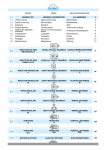
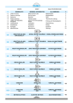
INDICE
1.0
1.1
1.2
1.3
1.4
1.5
1.6
1.7
1.8
1.9
GENERALITA’
Unità di misura
Fattore di servizio
Selezione
Potenza termica
Verifica del dispositivo
antiritorno
Lubrificazione
Installazione
Rodaggio
Manutenzione
INHALTSVERZEICHNIS
INDEX
GENERAL INFORMATION
Measurement units
Service factor
Selection
Thermal power
Check out of the backstop
device
Lubrication
Installation
Running-in
Maintenance
ALLGEMEINES
2
Maßeinheiten
Betriebsfaktor
Wahl
Thermische Leistung
2
2
4
5
Prüfung der Rücklaufsperre
6
Ölschmierung
Einbau
Einfahren
Wartung
8
9
10
10
2.0
RIDUTTORI AD ASSI
ORTOGONALI T
BEVEL HELICAL GEARBOX KEGELSTIRNRADGETRIEBE
T
T
3.0
RIDUTTORI AD ASSI
PARALLELI Z
PARALLEL SHAFT GEARBOX
Z
PARALLELENGETRIEBE
Z
45
4.0
RIDUTTORI PENDOLARI
P
SHAFT-MOUNTED GEARBOX
P
AUFSTECKGETRIEBE
P
69
5.0
RIDUTTORI PENDOLARI
M
SHAFT-MOUNTED GEARBOX
M
AUFSTECKGETRIEBE
M
85
6.0
RINVII ANGOLARI
R
RIGHT ANGLE GEARBOX
R
WINKELGETRIEBE
R
95
7.0
RINVII ANGOLARI
L
RIGHT ANGLE GEARBOX
L
WINKELGETRIEBE
L
111
8.0
RINVII ANGOLARI
RL
RIGHT ANGLE GEARBOX
RL
WINKELGETRIEBE
RL
127
9.0
VARIATORI
N
VARIATORS
N
VERSTELLGETRIEBE
N
135
10.0
VARIATORI
UDL
VARIATORS
UDL
VERSTELLGETRIEBE
UDL
147
11.0
MOTORI ELETTRICI
ELECTRIC MOTORS
ELEKTROMOTOREN
153
1
11
1.0
GENERALITA’
1.0
GENERAL INFORMATION
1.0
ALLGEMEINES
1.1
Unità di misura
1.1
Measurement units
1.1
Maßeinheiten
Tab. 1
SIMBOLO
SYMBOL
SYMBOL
DEFINIZIONE
DEFINITION
Bezeichnung
Fr 1-2
Carico Radiale
Radial load
Radialbelastung
N
Fa 1-2
Carico Assiale
Axial load
Axialbelastung
N
Dimensioni
Dimensions
Abmessungen
mm
Fattore di servizio
Service factor
Betriebsfaktor
FS
UNITA’ DI MISURA
MEASUREMENT UNIT
MAßEINHEIT
kg
Massa
Mass
Masse
kg
T2M
Momento torcente riduttore
Gearbox torque
Getriebe Drehmoment
Nm
T2
Momento torcente motorid.
Gearmotor torque
Getriebemotor Drehmoment
Nm
P
Potenza motore
Motor power
Motor Leistung
kW
Pc
Potenza corretta
Corrected power
Verbesserte Leistung
kW
P1
Potenza motoriduttore
Gearmotor power
Getriebemotor Leistung
kW
Pt0
Potenza termica
Thermal power
Thermische Leistung
kW
P'
Potenza richiesta in uscita
Output power
Erforderliche Abtriebsleistung
kW
RD
Rendimento dinamico
Dynamic efficiency
Dynamischer Wirkungsgrad
in
Rapp. di trasm. nominale
Rated reduction ratio
Nennuntersetzung
ir
Rapporto di trasmissione reale
Actual reduction ratio
Reelle Untersetzung
n1
Velocità albero entrata
Input speed
Antriebsdrehzahl
n2
Velocità albero uscita
Output speed
Abtriebsdrehzahl
Tc
Temperatura ambiente
Ambient temperature
Umgebungstemperatur
h
IEC
Rendimento
Motori accoppiabili
Efficiency
Motor options
Wirkungsgrad
Passende Motoren
1.2
Fattore di servizio
Il fattore di servizio FS permette di qualificare, in prima approssimazione, la tipologia dell’applicazione tenendo conto della
natura del carico (A, B, C), della durata
di funzionamento h/gg (ore giornaliere)
e del numero di avviamenti/ora. Il coefficiente così trovato dovrà essere uguale o
inferiore al fattore di servizio del riduttore
Fs’ dato dal rapporto fra la coppia nominale del riduttore T2M indicata a catalogo
e la coppia T2’ richiesta dall’applicazione.
1.2
Service factor
I valori di FS indicati nella tab. 2, sono
relativi all’azionamento con motore elettrico; se utilizzato un motore a
scoppio, si dovrà tenere conto di un
fattore di moltiplicazione 1.3 se a più
cilindri e 1.5 se monocilindro.
Se il motore elettrico applicato è autofrenante, considerare un numero di
avviamenti doppio di quello effetivamente richiesto.
1.2
Service factor FS enables approximate
qualification of the type of application,
taking into account type of load (A,B,C),
length of operation h/d (hours/day) and
the number of starts-up/hour. The coefficient thus calculated must be equal to or
lower than the gear unit service factor Fs’
which equals the ratio between T2M (gear
unit rated torque reported in the catalogue) and T2’ (torque required by the application).
FS' =
T2M
T2'
1Nm=0.1daNm @ 0.1kgm
1kW = 1.36 HP (PS)
1 min-1 = 6.283 rad.
°C
Betriebsfaktor
Der FS Betriebsfaktor ermöglicht die annähernde Bestimmung der Anwendungsart. Dabei werden Art der Last (A, B, C),
Betriebsstunden pro Tag (S/T) und Anzahl der Starts pro Stunde berücksichtigt.
Der so ermittelte Koeffizient sollte dem
Betriebsfaktor Fs’, der sich aus dem Verhältnis zwischen Nenndrehmoment des
Getriebes T2M (s. Katalog) und dem für
die Anwendung erforderlichen Drehmoment T2’ ergibt, entweder entsprechen
oder niedriger liegen.
> FS
FS values reported in table 2 refer to
a drive unit equipped with an electric
motor. If an internal combustion engine is used, a multiplication factor of
1.3 must be applied for a several-cylinder engine, 1.5 for a single- cylinder
engine.
If the electric motor is self-braking,
consider twice the number of starts-up
than those actually required.
2
min-1
1daN=10N @ 1kg
Die FS Werte, die in Tabelle 2 angegeben werden, beziehen sich auf den
Antrieb mit Elektromotor; falls ein Explosionsmotor verwendet wird, ist ein
Multiplikationsfaktor von 1.3 für Mehrzylindermotor und von 1.5 für Einzylindermotor zu berücksichtigen .
Falls der verwendete Elektromotor ein
Bremsmotor ist, so ist die Zahl der tatsächlich erforderlichen Startvorgänge
doppelt zu zählen.
Tab. 2
Classe di carico
Load class
Lastklasse
A
Carico uniforme
Uniform load
Gleichmaeßig verteilte Last
Classe di carico
Load class
Lastklasse
B
Carico con urti moderati
Moderate shock load
Mässige Laststöße
Classe di carico
Load class
Lastklasse
C
Carico con urti forti
Heavy shock load
Starke Laststöße
h/gg
h/d
St./Tag
4
8
16
24
N. AVVIAMENTI/ORA / N. START-UP/HOUR / ANZAHL DER STARTVORGÄNGE PRO STUNDE
2
0.8
1.0
1.3
1.5
4
8
125
250
500
0.8
0.9
0.9
1.0
1.1
1.1
1.0
1.1
1.1
1.3
1.3
1.3
1.3
1.3
1.3
1.5
1.5
1.5
1.5
1.5
1.5
1.8
1.8
1.8
APPLICAZIONI / APPLICATIONS / ANWENDUNGEN
1.2
1.3
1.5
1.8
1.2
1.3
1.5
1.8
Agitatori per liquidi puri
Alimentatori per fornaci
Alimentatori a disco
Filtri di lavaggio con aria
Generatori
Pompe centrifughe
Trasportatori con carico uniforme
h/gg
h/d
St./Tag
4
8
16
24
32
Pure liquid agitators
Fournace feeders
Disc feeders
Air laundry filters
Generators
Centrifugal pumps
Uniform load conveyors
63
Rührwerke für reine Flüssigkeiten
Beschickungsvorrichtungen für Brennöfen
Telleraufgeber
Spülluftfilter
Generatoren
Kreiselpumpen
Förderer mit gleichmäßig verteilter Last
N. AVVIAMENTI/ORA / N. START-UP/HOUR / ANZAHL DER STARTVORGÄNGE PRO STUNDE
2
1.0
1.3
1.5
1.8
125
250
500
1.0
1.0
1.0
1.3
1.3
1.3
1.3
1.3
1.3
1.5
1.5
1.5
1.5
1.5
1.5
1.8
1.8
1.8
1.8
1.8
1.8
2.2
2.2
2.2
APPLICAZIONI / APPLICATIONS / ANWENDUNGEN
4
8
1.3
1.5
1.8
2.2
1.3
1.5
1.8
2.2
Agitatori per liquidi e solidi
Alimentatori a nastro
Argani con medio servizio
Filtri con pietre e ghiaia
Viti per espulsione acqua
Flocculatori
Filtri a vuoto
Elevatori a tazze
Gru
h/gg
h/d
St./Tag
4
8
16
24
16
16
32
Liquid and solid agitators
Belt conveyors
Medium service winches
Stone and gravel filters
Dewatering screws
Flocculator
Vacuum filters
Bucket elevators
Cranes
63
Rührwerke für Flüssigkeiten und Feststoffe
Bandförderer
Mittlere Winden
Filter mit Steinen/Kies
Abwasserschnecken
Flockvorrichtungen
Vakuumfilter
Becherwerke
Kräne
N. AVVIAMENTI/ORA / N. START-UP/HOUR / ANZAHL DER STARTVORGÄNGE PRO STUNDE
2
1.3
1.5
1.8
2.2
125
250
500
1.3
1.3
1.3
1.5
1.5
1.5
1.5
1.5
1.5
1.8
1.8
1.8
1.8
1.8
1.8
2.2
2.2
2.2
2.2
2.2
2.2
2.5
2.5
2.5
APPLICAZIONI / APPLICATIONS / ANWENDUNGEN
4
1.5
1.8
2.2
2.5
1.5
1.8
2.2
2.5
Argani per servizio pesante
Estrusori
Calandre per gomma
Presse per mattoni
Piallatrici
Mulini a sfera
8
16
32
Heavy duty hoists
Extruders
Crusher rubber calenders
Brick presses
Planing machine
Ball mills
3
63
Winden für schwere Lasten
Extruder
Gummikalander
Ziegelpressen
Hobelmaschinen
Kugelmühle
1.3Selezione
1.3Wahl
1.3Selection
Determinare la potenza in entrata P’ (in Calculate input power P’ (on the basis of Bestimmen Sie die Antriebsleistung P’ (je
base alla coppia T2 richiesta dall’applica- the torque T2 required by the application), nach dem bei der Anwendung erforderzione) con la seguente formula:
using the following formula:
lichen Drehmoment T2) mit Hilfe der folgenden Formel:
Calcolare il rapporto di trasmissione con Calculate the transmission ratio with the Berechnen Sie das Untersetzungsverla relazione:
following equation:
hältnis mit Hilfe der Gleichung:
in =
n1
n2
Scegliere il fattore di servizio FS dell’ ap- Select the service factor FS of the appli- Wählen Sie den Betriebsfaktor FS der
plicazione nella Tab. 2.
cation in Table 2.
Anwendung aus der Tabelle 2 aus.
Scelta riduttore
A) n1 = 1400 min-1
Selecting a gearbox
A) n1 = 1400 min-1
Wahl des Getriebes
A) n1 = 1400 min-1
Si sceglierà nelle tabelle delle prestazioni Consult the gear unit efficiency table; sedei riduttori un gruppo che in corrispon- lect a group whose ratio is close to the caldenza di un rapporto prossimo a quello culated ratio and which permits power:
calcolato ammetta una potenza:
Aus der Tabelle der Leistungen der Untersetzungsgetriebe wählt man eine
Baugruppe aus, die ein ähnliches Untersetzungsverhältnis zu dem berechneten
Wert aufweist und die die folgende Leistung zulässt:
B) n1 ≠ 1400 min-1
Si dovrà effettuare la scelta come nel
caso precedente però in base ad una potenza Pc corretta con i coefficienti riportati
nelle tabelle relative ad ogni tipologia di
riduttore verificando la relazione:
B) n1 ≠ 1400 min-1
Make the selection as described above
but on the basis of power Pc corrected by
the coefficients reported in the tables .The
following equation should be checked
out:
B) n1 ≠ 1400 min-1
Die Wahl wird wie im obigen Fall ausgeführt, allerdings auf der Basis einer
Leistung Pc, die mit den Koeffizienten
korrigiert wurde. Dabei ist das folgende
Verhältnis zu überprüfen:
Scelta del motoriduttore
Selecting a gearmotor
Wahl des Getriebemotors
C) n1 = 1400 min-1 e FS = 1
Si cercherà nelle tabelle della prestazioni
dei motoriduttori un gruppo la cui potenza
P1 corrisponda alla P’ calcolata.
C) n1 = 1400 min-1 and FS = 1
Consult the gear motor efficiency table
and select a group having power P1 corresponding to calculated P’.
D) n1 ≠ 1400 min-1 o se il fattore FS ≠ 1
La scelta dovrà essere effettuata come
al punto A) verificando che la grandezza
del motore da installare sia compatibile
con quelle ammesse dal riduttore (IEC);
ovviamente la potenza installata dovrà
corrispondere al valore P’ richiesto.
D) n1 ≠ 1400 min-1 or FS ≠ 1
Follow the instructions at point A), checking that the size of the motor to be installed
is compatible with the gear unit (IEC); obviously, installed power must correspond
to the required P’ value.
C) n1 = 1400 min-1 und FS = 1
In den Leistungstabellen der Getriebemotoren sucht man eine Baugruppe, deren
Leistung P1 der berechneten Leistung P’
entspricht.
4
D) n1 ≠ 1400 min-1 oder FS ≠ 1
Die Auswahl wird wie unter A) getroffen,
wobei zu ueberpruefen ist, ob die Größe
des zu installierenden Motors mit dem
Untersetzungsgetriebe kompatibel ist
(IEC); selbstverständlich muß die Einbauleistung dem erforderlichen Wert P’
entsprechen.
Verifiche
Check-list
Überprüfungen
Verificare che i carichi radiali agenti sugli
alberi rientrino nei valori ammissibili riportati nelle relative tabelle.
Tali valori (FR2) si riferiscono a carichi che
agiscono a metà sporgenza dell’albero,
per cui se il punto di applicazione è diverso, è necessario effettuare il calcolo dei
nuovi valori ammissibili alla distanza (y)
desiderata.
Check that the radial loads on the shafts
fall within to the admissible values reported in the relative tables.
Reported values (FR2 refer to loads which
affect the shaft at the half-way point of its
projection; if the point of application is different, it is necessary to calculate the new
admissible values at the desired distance
(y).
Es ist zu ueberpruefen, ob die, dass die
auf die Wellen wirkenden Radiallasten
unter den in der Tabellen angegebenen
zulässigen Werten fallen.
Werte beziehen sich auf Lasten, die in
der FR2 Mitte der herausragenden Welle
wirken; bei verschiedenem Ansatzpunkt
ist es daher erforderlich, die neuen, beim
gewünschten Abstand (y) zulässigen
Werte zu berechnen.
Analogamente a quanto precisato sopra, In keeping with the above guidelines, axanche i carichi assiali dovranno essere ial loads should also be checked against
oggetto di verifica confrontandoli con i va- the values reported in the relative tables.
lori delle relative tabelle.
Ähnlich wie oben, müssen auch Axialbelastungen überprüft werden, indem man
sie mit den Werten der jeweiligen Tabellen vergleicht.
Überbelastungen
Eine augenblickliche Notfall-Überbelastung zu 100% des T2 Drehmoments darf
während Getriebestandardbetrieb eintreten.
Should frequent or higher overloads be Falls häufige und höhere Überlastungen
expected, it is necessary to install torque erwartet werden, sind die entsprechenlimiting devices.
den Vorrichtungen zur Begrenzung des
Drehmoments anzubringen.
Sovraccarichi
Durante il normale funzionamento del
riduttore è ammesso un sovraccarico
istantaneo di emergenza pari al 100%
della coppia indicata T2.
Se si temono sovraccarichi frequenti o
superiori è indispensabile prevedere degli opportuni dispositivi per la limitazione
della coppia.
Overloads
An emergency momentary overload up to
100% of T2 torque is allowed during standard operation of the gearbox.
Ingranaggi
Il calcolo a durata ed a fatica degli ingranaggi viene eseguito secondo la norma
ISO 6336 e ISO 10300, considerando
l’impiego di olio sintetico.
Gears
Life and fatigue of the gears are calculated in compliance with ISO 6336 and ISO
10300. Calculations refer to utilization of
synthetic oil
1.4
Potenza Termica
1.4
Thermal power
Räderwerk
Dauer und Belastung werden gemäß ISO
6336 und ISO 10300 berechnet. Dabei
wird die Anwendung von synthetischem
Oel berücksichtigt
1.4
Thermische Leistung
Nelle tabelle riportate nelle sezioni relative ad ogni tipologia di riduttore sono
indicati i valori della potenza termica nominale Pt0 (kW). Tale valore rappresenta
la potenza massima applicabile all’entrata del riduttore, in servizio continuo a
temperatura ambiente di 30°C, così che
la temperatura dell’olio non oltrepassi il
valore di 95°C, valore massimo ammesso
nel caso di prodotti standard.
The different sections dedicated to each
type of gearbox contain tables reporting
the values of rated thermal power Pt0
(kW). Reported values correspond to the
maximum admissible power at gearbox
input, on continuous duty and with ambient temperature of 30°C, so that oil temperature does not exceed 95°C, which is
the max. admissible value for standard
products.
Für jeden Getriebetyp gibt es Tabellen,
die die Nennwerte der thermischen Leistung Pt0 (kW) angeben. Die angegebenen Werte stellen die max. anwendbare
Antriebsleistung der Getriebe im Dauerbetrieb mit einer Umgebungstemperatur
von max. 30°C dar, sodass die Öltemperatur unter 95°C bleibt (max. Wert für
Standardprodukte).
Il valore di Pt0 non deve essere preso
in considerazione se il funzionamento è
continuo per un massimo di 1.5 ore seguito da pause di durata sufficiente (circa
1 – 2 ore) a ristabilire nel riduttore la temperatura ambiente.
Pt0 value should not be taken into account in case of continuous duty for max.
1.5 hours followed by pauses which are
long enough to bring the gearbox back
to ambient temperature (roughly 1 – 2
hours).
Pt0 Wert darf nicht betrachtet werden,
falls Dauerbetrieb max. 1.5 Stunden dauert und von Stillstand gefolgt wird, der
lang genug ist, damit das Getriebe zur
Umgebungstemperatur zurück kommt.
(ungefähr 1 – 2 Stunden).
I valori di Pt0 devono essere corretti tramite i seguenti coefficienti, così da considerare le reali condizioni di funzionamento,
ottenendo i valori di potenza termica corretta Ptc.
In order to comply with the actual operating conditions, Pt0 values should be corrected with the following coefficients, thus
obtaining the values of corrected thermal
power Ptc.
Pt0 Werte sollen durch die folgenden Koeffizienten verbessert werden, Damit die
reellen Betriebsbedingungen wirklich in
Betracht gezogen werden. Mit der folgenden Formel erhält man die Werte der korrekten thermischen Leistung Ptc.
5
Dove:
ft = coefficiente di temperatura (v. tab. 3)
Dabei ist:
ft = Temperaturkoeffizient (siehe Tabelle 3)
Where:
ft = temperature coefficient (see table 3)
Tab. 3
Tc (°C)
0
5
10
15
20
25
30
35
40
45
50
ft
1.46
1.38
1.31
1.23
1.15
1.1
1
0.92
0.85
0.77
0.69
(Dove Tc (°C) è la temperatura ambiente)
(Tc (°C) is the ambient temperature)
(Tc (°C) ist die Umgebungstemperatur)
fv = coefficiente di ventilazione
fv= 1.45 con ventilazione forzata efficace
con ventola dedicata
fv= 1.25 con ventilazione forzata secondaria ad altri dispositivi (pulegge, ventole motore, ecc.)
fv= 1 refrigerazione naturale (situazione standard)
fv= 0.5 in ambiente chiuso e ristretto (carter)
fv = cooling coefficient
fv= 1.45 forced cooling with specific fan
fu = coefficiente di utilizzo (v. tab. 4)
fu = utilization coefficient (see table 4)
fv = Luftkühlungskoeffizient
fv= 1.45 Drucklüftung mit
Sonderlüfterrad
fv= 1.25 Drucklüftung nebensächlich zu
fv= 1.25 forced cooling secondary to other anderen Vorrichtungen
devices (pulleys, motor fans, etc) (Scheiben, Motorlüfterräder,
usw.)
fv= 1
natural cooling (standard)
fv= 1 natürliche Lüftung (Standard)
fv= 0.5 in a closed and narrow
fv= 0.5 in engem und geschlossenem
environment
Raum
Tab. 4
fu = Verwendungskoeffizient (siehe
Tabelle 4)
Dt (min)
10
20
30
40
50
60
fu
1.6
1.35
1.2
1.1
1.05
1
Dove Dt sono i minuti di funzionamento in un’ora
Dt is minutes of operation per hour
Dt steht für Betriebsminuten pro Stunde
1.5 Verifica del dispositivo antiritorno 1.5 Check of back stop device
1.5
Dopo aver correttamente selezionato il
riduttore, occorre verificare se il valore
del momento torcente T2M max garantito
all’asse uscita del riduttore dal dispositivo
antiritorno, considerate le reali condizioni di esercizio, è sufficiente a garantire il
buon funzionamento dell’applicazione.
Deve pertanto essere verificata la seguente relazione:
After having selected the gearbox it is
necessary to check whether the max.
output torque T2Mmax guaranteed by the
backstop device, in view of the actual operating conditions, is sufficient to ensure
the good functioning of the application.
The following equation has to be checked
out:
Nach der Wahl des Getriebes muss sichergestellt werden, dass das von der
Rücklaufsperre garantierte Abtriebsdrehmoment T2M max hoch genug ist, damit
der korrekte Ablauf der Applikation unter
Berücksichtigung der wirklichen Betriebsbedingungen gewährleistet wird.
Die folgende Relation ist festzustellen:
Dove:
T2NOM [Nm]: è il momento torcente che
deve essere garantito all’asse uscita
del riduttore, nell’istante in cui viene
interrotta la trasmissione del moto,
affinché sia soddisfatta la condizione di irreversibilità del moto. T2NOM
dipende dalle specifiche dell’applicazione e deve essere valutato volta
per volta.
fc: fattore di carico
fc=1 in caso di funzionamento regolare
Dabei ist:
Where:
T2NOM [Nm]: is the torque that must be T2NOM [Nm]: Drehmoment, das am Getrieguaranteed at gearbox output when
beabtrieb garantiert werden muss,
motion transmission is stopped, in
wenn die Übertragung der Beweorder that motion irreversibility is engung stoppt, damit Irreversibilität gesured. T2NOM depends on application
währleistet wird. T2NOM hängt ab von
features and should be assessed
den Merkmalen der Applikation, d. h.
each time.
T2NOM muss jeweils bewertet werden.
fc=1.3 in caso di funzionamento con urti
moderati
fc=1.8 in caso di funzionamento con forti
urti
NOTA:
Per funzionamento regolare si intende
il caso in cui il dispositivo antiritorno, in
attesa della ripresa della normale attività del riduttore, mantiene la macchina
ferma. Se invece, nel momento in cui il
dispositivo antiritorno è azionato (quindi
il riduttore è fermo), il carico in uscita aumenta di intensità si possono avere degli
urti (moderati o forti).
Prüfung der Rücklaufsperre
fc: load factor
fc=1 in case of standard operation
fc:Last-Faktor
fc=1 bei Standardbetrieb
Note:
By standard running we mean that the
back stop device keeps the machine
stationary, whilst awaiting the restart of
the gearbox operation. On the contrary
in case the back stop device is enabled
(motionless gearbox) and the output load
gets heavier, moderate or heavy shocks
might occur.
ANMERKUNG:
Im Standartbetrieb wird der Abtrieb bei
einem Maschinenstopp durch die Rücklaufsperre blockiert. Ein erneuter Start
löst die Rücklaufsperre wieder. Treten im
Stillstand mässige oder starke Laststösse
auf, müssen diese bei der Getriebeauslegung berücksichtigt werden.
fc=1.3 in case of operation with moderate shocks
fc=1.8 in case of operation with heavy
shocks
6
fc=1.3 bei Betrieb mit mäßigen Stößen
fc=1.8 bei Betrieb mit starken Stößen
fa: fattore di applicazione, ricavabile dal- fa: application factor, as shown in the fa: Anwendungsfaktor, wie es in der folla seguente tabella (tab. 5) in funziofollowing table (tab. 5), depending
genden Tabelle (Tab.5) angegeben
ne del numero di inserzioni/ora e dal
on the number of backstop device inwird. Der Anwendungsfaktor hängt
numero di ore di funzionamento al
sertions per hour and the number of
von der Zahl der Einschaltungen der
giorno del riduttore
gearbox operating hours per day.
Rücklaufsperre pro Stunde und von
Betriebsstunden des Getriebes pro
Tag ab.
Tab. 5
n° INSERZIONI / h - INSERTIONS / H - NR. EINSCHALTUNGEN / STUNDE
h/gg - h/d - St./Tag
2
4
8
16
32
63
8
1
1
1.1
1.2
1.3
1.4
16
1.3
1.3
1.4
1.5
1.6
1.7
24
1.5
1.5
1.6
1.7
1.8
1.9
ft: fattore di temperatura ricavabile dalla ft: temperature factor, as shown in the ft: Temperaturfaktor, wie es in der folseguente tabella (tab.6) in funzione
following table (tab. 6) depending on
genden Tabelle (Tab.6) angegeben
della temperatura ambiente di funzioambient temperature during gearbox
wird. Der Temperaturfaktor hängt
namento.
operation.
von der Umgebungstemperatur während des Getriebebetriebs ab.
.
Tab. 6
Tamb (°C)
-20°
-10°
0°
10°
20°
30°
40°
50°
ft
1.2
1.15
1.1
1.05
1
1.03
1.05
1.10
Se la relazione (1) a pag. 6 non risulta
essere verificata si prenda in considerazione la possibilità o di variare il rapporto
di riduzione, individuando una alternativa
migliore, o di passare alle grandezze di
riduttori successive.
If the result of the calculation does not
correspond to the equation (1) at page
6, either the ratio has to be modified or a
bigger size of gearbox has to be selected.
Falls das Resultat nicht der Relation
(1) entspricht (Seite 6), muss entweder
das Untersetzungsverhältnis oder die
Größe des Getriebes geändert werden.
Nel caso in cui il riduttore, provvisto di dispositivo antiritorno, si trovi ad operare ad
una temperatura ambiente minore di 0°C
il riduttore può essere fornito, a seconda
del rapporto di riduzione, in esecuzione
speciale (con camera stagna) così da migliorare il funzionamento del dispositivo.
Per quanto riguarda quest’ultima soluzione si contatti il servizio tecnico Tramec.
If the ambient temperature is below 0°C,
the gearbox with backstop device can be
supplied in the special execution (with
tight chamber) which improves the functioning of the backstop device.
Please contact Tramec Technical Dept.
for further information.
Liegt die Umgebungstemperatur unter
0°C, wird empfohlen, die Sonderausführung des Getriebes (mit Dichtkammer) zu
benutzen, damit die Rücklaufsperre am
besten funktioniert.
Für weitere Auskünfte darüber soll man
sich mit Tramec technischen Büro in Verbindung setzen.
7
1.6
Lubrificazione
1.6
Lubrication
1.6
Ölschmierung
I cuscinetti dell’albero veloce vengono
sempre lubrificati con grasso a base sintetica; altri cuscinetti vengono lubrificati
solo se la posizione di montaggio non ne
garantisce la corretta lubrificazione.
The bearings mounted on the input shaft
are supplied with grease, synthetic base;
the other bearings are lubricated only if
the mounting position does not assure a
correct lubrication.
Una scelta oculata del tipo di lubrificante, in funzione delle condizioni operative
e ambientali, consente ai riduttori di raggiungere le prestazioni ottimali.
Le prestazioni dei riduttori indicate nelle
tabelle dei dati tecnici sono state calcolate considerando l’impiego di olio sintetico.
Choose the lubricant according to operating and ambient conditions in order to
ensure high gear unit performance.
Performance data, as shown in the specifications tables, refer to utilization of synthetic oil.
VISCOSITA’
E’uno dei parametri più importanti da
considerare nella scelta di un olio ed è
influenzabile da diversi parametri quali
velocità, temperatura. Riportiamo sinteticamente le valutazioni generali per la
scelta della giusta viscosità:
VISCOSITY
It is the most important parameter to be
considered when selecting an oil; it depends on various factors such as speed
and temperature. Following are general
guidelines for choosing the correct viscosity:
VISKOSITÄT
Die Viskosität ist eines der wichtigsten Merkmale, die bei der Auswahl des
richtigen Öls zu beachten sind; sie wird
von verschiedenen Parametern wie Geschwindigkeit und Temperatur beeinflußt.
Im folgenden fassen wir die wichtigsten
allgemeinen Hinweise für die Wahl der
richtigen Viskosität zusammen:
Viscosità alta
Usare per basse velocità di rotazione e/o
temperature alte. (Una viscosità troppo
bassa in queste condizioni operative causa una usura precoce).
High viscosity
To be used for low rotation speed and/or
high temperatures. (Under these operating conditions a low viscosity causes premature wear).
Hohe Viskosität
Geeignet für niedrige Drehzahlen bzw.
hohe Temperaturen. (Eine zu geringe Viskosität verursacht unter diesen Betriebsbedingungen frühen Verschleiß).
Viscosità bassa
Usare per alte velocità di rotazione e/o
temperature basse.
(Una viscosità troppo elevata provoca diminuzione del rendimento e surriscaldamento).
Low viscosity
To be used for high rotation speed and/or
low temperatures.
(High viscosity reduces efficiency and
causes overheating).
Geringe Viskosität
Geeignet für hohe Drehzahlen bzw. niedrige Temperaturen.
(Eine zu hohe Viskosität führt in diesem
Fall zu einer Verringerung des Wirkungsgrades und zur Überhitzung).
ADDITIVI
In tutti gli oli minerali sono contenuti degli
additivi antiusura, EP (più o meno energici), antiossidanti ed antischiuma. E’ opportuno assicurarsi che essi siano blandi
e non agressivi nei confronti delle guarnizioni.
ADDITIVES
All mineral oils contain additives to protect against wear, EP (more or less
strong), anti-oxidizing and anti-frothing. It
is advisable to make sure that the action
of such additives is bland and not too aggressive on the seals.
ZUSAETZE
Alle Mineralöle enthalten AntiverschleißZusätze, EP (mehr oder weniger stark),
Oxydationsschutzmittel und Mittel gegen
Schaumbildung. Es soll sichergestellt
werden, daß diese Zusätze schwach sind
und die Dichtungen nicht angreifen.
BASE DELL’OLIO
Può essere minerale o sintetica.
L’ olio sintetico, compensa il costo più elevato con una serie di vantaggi:
OIL BASE
öLGRUNDLAGE
May be mineral or synthetic.
Es kann sich dabei um Mineralöl oder
Synthetic oil compensates for the higher synthetisches öl handeln.
cost with a series of advantages :
Synthetisches öl ist kostenintensiver, bietet jedoch viele Vorteile:
a) minor coefficiente d’attrito (quindi
migliore rendimento)
a) lower friction coefficient (consequently
improved efficiency)
a) geringerer Reibungskoeffizient (besserer Wirkungsgrad)
b) migliore stabilità nel tempo (possibile
lubrificazione a vita)
b) better stability over time (possible
life lubrication)
b) höhere Stabilität über lange Zeit (lebenslange Schmierung möglich)
c) migliore indice di viscosità (migliore la
adattabilità alle varie temperature).
c) better viscosity index (more adaptable
to various temperatures).
c) besserer Viskositätsindex (passt sich
besser an Temperaturschwankungen an).
Die Kugellager auf der Eingangswelle werden immer mit synthetischem Fett geliefert.
Falls die Montage keine korrekte Schmierung gewährleistet, dann werden die restlichen Lager mit Schmiermittel geliefert.
Das Untersetzungsgetriebe wird optimal arbeiten, wenn das richtige Schmiermittel je
nach Betriebs- und Umgebungsbedingungen sorgfältig ausgewählt wird. Daten über
Getriebeleistung, wie es in den Tabellen
der technischen Daten angegeben wird,
beziehen sich auf Schmierung mit synthetischem Öl.
L’ olio a base minerale come vantaggi ha Mineral-base oils offer the advantages of Die Vorteile von Mineralöl sind die niedil minore costo e un migliore comporta- costing less and performing better during rigeren Kosten und das bessere Einfahrmento in rodaggio.
the running-in period.
verhalten.
8
OLIO MINERALE / MINERAL OIL / MINE- OLIO SINTETICO / SYNTHETIC OIL / SYNTETISCHES
RALÖL
ÖL
ISO VG
Temperatura ambiente
Amb.Temp.
Tc (°C)
Umgebungstemperatur
460
320
220
460
320
220
150
5° a 45°
0° a 40°
-5° a 35°
-15° a 100°
-20 a 90°
-25° a 80°
-30° a 70°
1.7
MINERALE / MINER. / MINER.
SHELL
Omala
OIL 460
Omala
OIL 320
Omala
OIL 220
BP
Energol
GRXP 460
Energol
GRXP 320
Energol
GRXP 220
TEXACO
Meropa
460
Meropa
320
Meropa
220
CASTROL
Alpha SP 460
Alpha SP
320
Alpha SP
220
KLUBER
Lamora
460
Lamora
320
Lamora
220
MOBIL
Mobilgear
634
Mobilgear
632
Mobilgear
630
PAG
Tecnologia PAG (polialcoliglicoli) / PAG Tecnology (polyalkyleneglycol) / PAG (Polyalkylglikole)
SHELL
Omala S4
WE 460
Omala S4
WE 320
Omala S4
WE 220
Omala S4
WE 150
BP
Energol
SGXP460
Energol
SGXP320
Energol
SGXP220
Enersyn
SG 150
TEXACO
Synlube
CLP 460
Synlube
CLP 320
Synlube
CLP 220
Agip Blasia
S 320
Agip Blasia
S 220
AGIP
Agip Blasia
S 150
Tecnologia PAO (polialcoliolifini) / PAO Tecnology (polialphaolefin) / PAO (Polyalphaolefine)
PAO
FORNITORE / MANUFACTURER / HERSTELLER
MINERALE / MINERAL / MINERAL
SHELL
Omala OIL
RL/HD 460
Omala OIL
RL/HD 320
Omala OIL
RL/HD 220
Omala OIL
RL/HD 150
CASTROL
Alpha Synt
460
Alpha Synt
320
Alpha Synt
220
Alpha Synt
150
KLUBER
Synteso
D460 EP
Synteso
D320 EP
Synteso
D220 EP
Synteso
D150 EP
MOBIL
SHC 634
SHC 632
SHC 630
SHC 629
Installazione
1.7
Installation
1.7
Einbau
Montare il riduttore in modo tale da elimi- Install the gearbox so that any vibration is Das Getriebe ist so zu montieren, daß
nare qualsiasi vibrazione.
eliminated.
Schwingungen ausgeschaltet werden.
Curare particolarmente l’allineamento del
riduttore con il motore e la macchina da
comandare interponendo dove è possibile giunti elastici od autoallineanti.
Take special care with the alignment be- Insbesondere ist auf die Fluchtung des
tween the gear units, the motor and the Getriebes zum Motor und zur Maschine zu
driven machine, fitting flexible or self ad- achten, wo möglich sind elastische oder
justing couplings wherever possible.
selbstfluchtende Kupplungen anzubringen.
Quando il riduttore è sottoposto a sovraccarichi prolungati, urti o pericoli di bloccaggio, installare salvamotori, limitatori di
coppia, giunti idraulici od altri dispositivi
similari.
If the gearbox is subject to prolonged
overloads, shocks or possible jamming,
fit overload cutouts, torque limiters, hydraulic couplings or other similar devices.
Wenn das Getriebe anhaltenden Überlasten, Schlägen oder Blockierungsgefahr
ausgesetzt ist, sind Motorschalter, Drehmomentbegrenzer, hydraulische Kupplungen
oder ähnliche Vorrichtungen anzubringen.
Achten sie darauf, dass die zulässigen
Fare attenzione a non superare i valori Do not exceed allowed radial and axial Radial-und Axialbelastungen an Antriebsconsentiti di carico radiale ed assiale che loads on the input and output shafts.
und Abtriebswelle nicht überschritten
agiscono sugli alberi veloce e lento.
werden.
Achten Sie darauf, dass die am Getriebe
Assicurarsi che gli organi da montare sui Ensure that the components to be fitted montierten Elemente mit folgenden Toleriduttori siano lavorati con tolleranza
on the gear units are machined with toler- ranzen bearbeitet sind: WELLE ISO h6,
ALBERO ISO h6 FORO ISO H7.
ance SHAFT ISO h6 HOLE ISO H7.
BOHRUNG ISO H7.
9
Prima di effettuare il montaggio pulire e Before assembling, clean and lubricate Vor der Montage sind die Flächen zu reilubrificare le superfici al fine di evitare il the surfaces to prevent seizure and con- nigen und zu schmieren, um Festfressen
pericolo di grippaggio e l’ossidazione da tact oxidation.
bzw. Kontaktoxidation zu vermeiden.
contatto.
Il montaggio va effettuato con l’ausilio di
tiranti ed estrattori utilizzando il foro filettato posto in testa alle estremità degli
alberi.
Durante la verniciatura si consiglia di
protteggere il bordo esterno degli anelli di
tenuta per evitare che la vernice ne essichi la gomma pregiudicando la tenuta del
paraolio stesso.
Assembly is to be carried out with the
aid of tie-rods and extractors, using the
threaded hole at the shaft ends.
When painting, protect the outside edge
of the oil seals to prevent the paint from
drying the rubber and impairing sealing
properties.
Die Montage erfolgt mit Hilfe von Zugstangen und Ausziehvorrichtungen unter
Verwendung der Gewindebohrung vorn
an den Wellenenden.
Während des Lackierens sollte der Außenrand der Dichtungsringe geschützt
werden, um zu vermeiden, daß der Lack
den Gummi austrocknet, was die Dichtungen beeinträchtigen könnte.
Prima della messa in funzione della macchina accertarsi che la quantità di lubrificante e la posizione dei tappi di livello
e sfiato siano conformi alla posizione di
montaggio del riduttore e che la viscosità del lubrificante sia adeguata al tipo di
carico.
Se il riduttore viene installato all’aperto si
consiglia l’utilizzo del tappo di sfiato con
valvola.
Tutti i riduttori e motoriduttori citati nel
presente manuale sono destinati ad un
impiego industriale con temperatura ambiente da -20°C a +40°C ad una altitudine
max di 1000 m slm.
Before starting up the machine, check
that the amount of lubricant and the position of filler and breather plugs are correct for the gear unit mounting position
and that the lubricant viscosity is appropriate for the type of load.
Bevor die Maschine in Betrieb genommen wird, ist sicherzustellen, daß sowohl die Schmiermittelmenge als auch
die Position der Ölstand- und der Entlüftungschraube der Montageposition
des Getriebes entsprechen und daß die
Schmiermittelviskosität der Belastungsart
entspricht.
Die Anwendung einer Entlüftungsschraube mit Ventil wird empfohlen, wenn das
Getriebe im Freien eingebaut wird.
Alle im vorliegenden Katalog angegebenen Getriebe und Getriebemotoren sind
für industriellen Einsatz in einer Umgebungstemperatur von -20°C bis +40°C
und in einer max. Höhe von 1000 m über
dem Meeresspiegel vorgesehen.
Für weitere Anweisungen laden Sie die
“Betriebs- und Instandhaltungsanweisung“
aus unsere Webseite www.tramec.it herunter.
If the gearbox is installed outdoors, we
reccomend the use of the breather plug
with valve.
All reducers and gear motors mentioned
in this catalog are intended for industrial
use and operation at a ambient temperature between -20°C and +40°C, at an altitude of max. 1000 m above sea level.
Per tutte le altre avvertenze consultare il For all other instructions check the
manuale di “uso e manutenzione” scari- “Use and Maintenance Manual” which
cabile dal sito www.tramec.it
can be downloaded from our web site
www.tramec.it
1.8
Rodaggio
1.8
Running-in
Si consiglia di incrementare gradualmen- Increase the transmitted power gradually
te nel tempo la potenza trasmessa oppu- or limit the resistant torque of the driven
re limitare il momento torcente resistente machine for the first few operating hours.
della macchina da comandare per le prime ore di funzionamento.
1.9
Manutenzione
Per i riduttori lubrificati con olio minerale
dopo le prime 500 - 1000 ore di funzionamento sostituire l’olio effettuando, se
possibile, un accurato lavaggio interno
del riduttore.
Controllare periodicamente il livello del
lubrificante ed effettuare il cambio dopo
4000 ore di funzionamento.
Se è utulizzato olio sintetico il cambio può
essere effettuato dopo 12500 ore di funzionamento.
Quando il riduttore resta per lungo tempo
inattivo in un ambiente con una elevata
percentuale di umidità si consiglia di riempirlo completamente di olio.
Naturalmente al momento della successiva messa in funzione sarà necessario
ripristinare il livello del lubrificante.
1.9
Maintenance
Gear units lubricated with mineral oil,
change the oil after the first 500 – 1000
operating hours and if possible thoroughly flush the inside of the gearbox.
Check the lubricant level regularly and
change after 4000 operating hours. If synthetic oil is used the oil change may take
place after 12500 running hours.
When the gearbox is left unused in a
highly humid environment fill it completely
with oil.
Importantly the oil must be returned to
the operating level before the unit is used
again.
10
1.8
Einfahren
Es ist ratsam, die Leistung nur allmählich
zu steigern oder das Widerstandsdrehmoment der Maschine in den ersten Betriebsstunden zu begrenzen.
1.9
Wartung
Bei mit Mineralöl geschmierten Getrieben
ist nach den ersten 500 bis 1000 Betriebsstunden ein Ölwechsel durchzuführen,
dabei sollte das Getriebeinnere möglichst
ausgespült werden.
Von Zeit zu Zeit ist der Ölstand zu prüfen, alle 4000 Betriebsstunden sollte ein
Ölwechsel stattfinden.
Bei Verwendung von Synthetiköl kann der
Ölwechsel alle 12500 Betriebsstunden
erfolgen.
Wenn das Getriebe lange Zeit in einem
Raum mit hoher Luftfeuchtigkeit stillliegt,
ist es ratsam, es ganz mit Öl zu füllen.
Wird es danach wieder in Betrieb genommen, so ist natürlich vorher der richtige
Ölstand wiederherzustellen.
8.0
RINVII ANGOLARI RL
RIGHT ANGLE GEARBOX RL WINKELGETRIEBE
8.1
8.2
8.3
8.4
8.5
8.6
Caratteristiche
Designazione
Fattore di servizio FS
Dati tecnici
Carichi radiali e assiali (N)
Dimensioni
Characteristics
Designation
Service factor FS
Technical data
Radial and axial loads (N)
Dimensions
Merkmale
Bezeichnung
Betriebsfactor FS
Technische Daten
Radial und axial Belastungen (N)
Abmessungen
128
129
130
130
130
131
04/2014
127
I rinvii angolari serie RL sono stati progettati per applicazioni industriali ove occorra trasmettere un moto rotatorio di potenza tra alberi disposti perpendicolarmente
tra loro.
Possono essere a 2 o 3 uscite con rapporto di trasmissione:1:1 o 2:1.
8.1
Caratteristiche
Carter
The right angle gearboxes RL Series have
been designed for industrial applications
when rotary power must be transferred to
the shafts perpendicularly arranged. They
could have 2 or 3 output shafts and have
1:1 or 2:1 ratio.
8.1
Characteristics
Die Winkelgetriebe der Serie RL sind für
den industriellen Einsatz ausgelegt und
wenn die Drehbewegung um 90° umgelenkt werden muss. Die Getriebe sind mit
2 oder 3 Wellenenden ausgeführt und
können mit Untersetzungsverhältnissen
von 1:1 oder 1:2 geliefert werden.
8.1
Merkmale
Gehäuse
Housing
Monoblocco rigido in lega d’alluminio con Single-piece aluminium alloy casting with Starres Getriebegehäuse aus Leichtmetall mit 5 Befestigungsflächen und 3 Zent5 piani di attacco e 3 possibilità di cen- 5 mounting points and 3 flanges.
riermöglichkeiten.
traggio.
Ingranaggi
Gears
Verzahnung
Conici a dentatura spiroidale GLEASON.
Sono costruiti in acciaio al Nickel-Cromo
e sottoposti ad un trattamento superficiale di cementazione e tempra e successivo
rodaggio. Il gioco angolare fra gli ingranaggi è regolato per garantire un ingranamento ed una silenziosità ottimali; a
richiesta possono essere forniti con gioco
angolare ridotto fino a 5’.
Bevel gears GLEASON toothed are made
of Nickel – Chrome steel and are submitted to a surface case - quench hardening
treatment before the running in.
The backlash between gears ensures
maximum service life and very low noise
level. Back lash tolerances can be reduced to a minimum of 5’ if specifically
requested.
Die auf Gleason-Maschinen hergestellten
Kegelräder sind aus Nickel-Chrome Stahl
und wurden vor dem Einlaufen einsatzgehärtet. Das Zahnflankenspiel zwischen
den Rädern ist für optimale Eingriffseigenschaften und Laufruhe ausgelegt, auf
Wunsch kann das Spiel bis auf 5’ reduziert werden.
Alberi
Shafts
Wellen
Sono costruiti in acciaio con una resistenza di 80 Kg/mm2 e protetti superficialmente contro la corrosione.
L’attacco esterno è previsto con un trascinamento a linguetta a norma UNI (ad eccezione della grandezza 1). Le posizioni
angolari delle linguette sugli alberi entrata
e uscita non hanno particolari riferimenti
tra loro.
The shafts are made of steel with 80Kg/
mm2 resistance and surface treated
against corrosion.
The external coupling is carried out by
means of a key UNI standard (except for
the size 1) . Keyways can be made at
any angle, no special references between
them are necessary.
Die aus speziell behandeltem Stahl mit
einer Festigkeit von 80 kg/mm2 gefertigten Wellen sind korrosiongeschützt.
Die Abtriebswelle ist mit Passfedernut
nach UNI – Norm versehen (mit Ausnahme der Baugrösse 1). Die Passfedern
können jede beliebige Winkelposition einnehmen.
Cuscinetti
Bearings
Lager
Sono a sfere, largamente dimensionati e Ball bearings liberally dimensioned and Grosszügig dimensionierte Kugellager
a gola profonda.
mit tiefer Laufrille.
with deep races.
Tenute lubrificante interno
Dichtungen
Oilseals
Con anelli di tenuta su tutti i modelli.
Alle Winkelgetriebe sind mit Dichtringen
Oilseal rings are fitted to all models.
A richiesta sono disponibili anelli speciali Special seal rings for high or low temper- versehen. Auf Anfrage sind Sonderdichper alte o basse temperature.
tringe für hohe bzw niedrige Temperatuatures are available upon request.
ren lieferbar.
Lubrificazione
Lubrication
Schmierung
I rinvii vengono forniti già equipaggiati di
lubrificante: la grandezza 31 con grasso
permanente; tutte le altre grandezze con
olio.
The right angle gearboxes are supplied
complete with lubrication: the size 31 is
filled with long life grease; the other sizes
are filled with oil.
Die Winkelgetriebe werden mit Schmiermittel geliefert. Die Baugröße 31 ist mit
Lebensdauer-Fett-Schmierung gefüllt, die
anderen Größen sind mit Öl geschmiert.
128
8.2Designazione
8.2Bezeichnung
32
AB
1:1
3FL
RL
31
32
33
34
42
AB
AC
BC
1:1
2:1
3FL
Versione
Version
Ausführung
Pos. alberi
Shaftsq position
Wellenposition
RL
Macchina
Machine
Maschine
Tipo
Type
Typ
Rapporto rid.
Ratio
Untersetzungsverhältnis
8.2Designation
Posizione alberi e sensi di rotazione
Shafts position and direction of rotation
Wellenposition und Drehrichtung
PA = albero entrata
B = albero uscita lato corona conica
C = albero uscita lato opposto alla corona
conica
A = Input shaft
B = Output shaft on ring bevel gear side
C = Ouput shaft on opposite side to ring
bevel gear
A = Antriebswelle
B = Abtriebswelle auf Kegelkranzseite
C = Abtriebswelle auf der gegenüberliegenden Seite des Kegelkranzes
Le figure mostrano, per ogni versione, i For each version the following pictures will Die Abbildungen zeigen für jede Version
sensi di rotazione degli alberi.
show the direction of rotation of the shafts die entsprechende Drehrichtung der Welle.
Per ogni versione, lo stesso rinvio è rap- The right angle gearbox is shown in two po- Für jede Version wird das gleiche Getriepresentato in due posizioni ruotate di sitions turned by 180°.
be in zwei, jeweils um 180° gedrehten Po180°.
sitionen dargestellt.
129
Fattore di servizio FS
8.3
Service factor FS
8.3
8.3
h/d
ore di funzionamento giornaliere
working hours per day
Tägliche Betriebszeit in Std.
h/d
3
8
12
24
A
0.7
0.9
1
1.3
B
0.9
1
1.3
1.8
C
1.3
1.6
1.8
2.3
Betriebsfactor FS
A
carico uniforme
uniform load
Gleichmäßiger Betrieb
B
carico con urti modesti
load with moderate shocks
Mittelstarke Stöße beim Betrieb
C
carico con urti
load with shock
Starke Stöße beim Betrieb
N.B.
Verificare che la temperatura di esercizio
non superi i valori da
-20°C a +80°C.
Nel caso del rapporto 2:1 non usare il
rinvio in moltiplicazione (cioè entrando
dall’albero B o C) oltre 700 giri al minuto.
N.B.
check that the operating temperature does
not exceed the values -20°C / + 80°C.
If you require a 2:1 ratio, do not use a speed
multiplier (i.e. with inputs on shaft B or C)
which operates at more than 700 rpm.
N.B.
Die Betriebstemperatur sollte nicht außerhalb des folgenden Bereichs liegen:
-20°C / + 80°C.
Falls die Getriebe als Übersetzungsgetriebe (ins Schnelle) verwendet werden
sollen, ist darauf zu achten, dass die
Antriebsdrehzahl an der Welle B oder C
700Upm nicht überschreiten darf.
Dati tecnici
8.4
RL 31
n2
[min-1]
3000
1400
1000
600
300
100
50
RL32
RL33
8.4
RL34
RL42
i
1:1
2:1
1:1
2:1
1:1
2:1
1:1
2:1
1:1
2:1
T2 [Nm]
2.0
—
7.7
—
20.2
—
33
—
5.7
—
P1(kW)
0.63
—
2.5
—
6.5
—
11
—
1.7
—
T2 [Nm]
2.4
0.9
8.6
4.2
25.2
17.9
42
29.5
8.4
6.7
P1(kW)
0.37
0.14
1.3
0.65
3.9
2.8
6.5
4.5
1.2
0.94
T2 [Nm]
2.6
1.0
9.2
4.5
27.1
19
46
33
9.8
8.0
P1(kW)
0.29
0.11
1.0
0.50
3.0
2.1
5.1
3.6
0.98
0.80
T2 [Nm]
2.9
1.1
10
5
29.7
21
53
37
12.4
10.2
P1(kW)
0.19
0.07
0.67
0.33
2.0
1.4
3.5
2.5
0.75
0.62
T2 [Nm]
3.4
1.3
11.6
5.6
34.7
23
63
41
16.4
13.9
P1(kW)
0.11
0.04
0.39
0.19
1.2
0.77
2.1
1.4
0.50
0.42
T2 [Nm]
4.2
1.5
14.5
6.2
44
26
79
44
25.4
22
P1(kW)
0.05
0.02
0.16
0.07
0.49
0.29
0.89
0.49
0.25
0.22
T2 [Nm]
4.7
1.7
16.5
6.7
50.5
27
89
46
33
25.7
P1(kW)
0.03
0.01
0.09
0.04
0.28
0.15
0.5
0.26
0.17
0.13
Kg
8.5
Technical data
8.4
0.3
1.2
Carichi radiali e assiali (N)
Fr
Fa
RL31
210
110
RL32
410
200
RL33
760
430
RL34
880
490
3.5
8.5
5.7
Simbolo
Symbol Definizione Definition Definition
Symbol
n2
Giri uscita
Output
revs
Umdrehungen
Abtrieb
i
Rapporto
Ratio
Untersetzung
T2
Coppia
uscita
max.
Max.
output
torque
Max.
Abtriebsdrehzahl
P1
Potenza
entrata
Input
power
Antriebsleistung
Kg
Massa
Masse
Masse
2
Radial and axial loads (N)
Fr:
Carico radiale max. N applcato a metà della
sporgenza dell’albero
Max radial load in N applied mid of shaft
extension
Max. Radialbelastung in N bei der halben
Länge der herausragenden Welle
130
Technische Daten
8.5
Radiale und Axiale
Belastungen (N)
Fa:
Carico assiale max. N
Max. axial load in N
Axial - Belastung (max) in N
8.6
Dimensioni
8.6
Dimensions
RL 31
8.6
Abmessungen
3FL
131
8.6
Dimensioni
8.6
Dimensions
8.6
Abmessungen
RL 32 - RL 33 - RL 34
A
B
C
Df7
b
t1
E
F
3FL
G
H
I
L
N
O
O1
P
QH6
RH6
S
T
U
V
Z
RL 32
52
18
66
15
5
12
35
26
6.2
50
7
52
24
24
24
8.3
35
–
5
90
–
104
27
RL 33
76
27
96
20
6
16.5
50
38
8.3
74
8
75
38
38
38
8.3
55
52
3.5
140
5
150
40
RL 34 100
38
98
25
8
21
70
38
10.3
98
13
80
45
45
70
10.3
65
62
3.5
150
2
160
60
132
8.6
Dimensioni
8.6
Dimensions
RL 42
8.6
Abmessungen
3FL
133
134