1
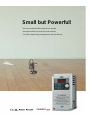
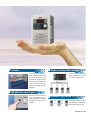
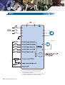
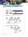
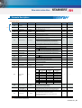
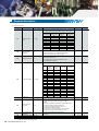
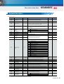
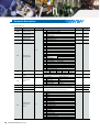
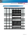
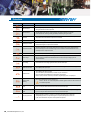
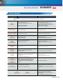
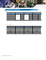
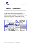
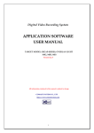
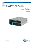
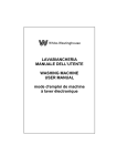
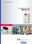
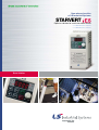
New micro size drive
of LS Industrial Systems
STARVERT
Optimum solution for small size motor control
0.1~0.4kW 1Phase 200~230Volts
0.1~0.4kW 3Phase 200~230Volts
Drive Solution
Experience the power!
04
06
07
08
09
10
Key features of product
Model and Specifications
Standard Specification
Wiring
Terminal and loader functions
Shifts between each code and group
12
18
19
20
21
Function code table
Protections
Check & Remedy
Peripheral device Specifications
Dimension
Small but Powerful!
We have created the Micro class drive to provide
the optimal solution for small size motor controls.
You will be experiencing amazing power with this slim size.
STARVERT
STARVERT iE5 _ 03
Slim and variety!
Our iE5 is best fit for small machineries
such as packing machines, small conveyers, treadmills and etc...
Smaller micro size
Easy operation and control
Our iE5 realizes 5% smaller micro size comparing to previous product.
The operation became easy by adopting the 6 keys and volume resistor types
on the loader. Besides, convenience is guaranteed by limiting the total number
of parameters as 100 parameters.
15%
Light on in editing mode
Light on in drive operation
●
●
●
Light on in forward operation
●
Light on in reverse operation
128mm
●
●
●
●
●
●
●
Use to change operation frequency
Use for drive operation
A reset key when the stop key is fault during drive operation
85mm
68mm
*For 400W model
Use between group shifts or parameter setting.
This key moves to the left the digit position
Use parameter set value change and save
SV002 iE5-1
Use for code shifts and parameter set value increase
Use for code shifts and parameter set value decrease
04 _ LS Industrial Systems Co., Ltd.
PI Control
PI Control
60Hz
V/F Control
Modbus communication interface (optional)
The PI Control is used to control the
The optional modbus communication
oil level, temperature and pressure of
enables controlling drives through
plant and process.This drive speed
PLC and other controlling devices.
control function compares between
drive setting value and signal values
Modbus-RTU
gauged from sensors and actual
control is made through Proportion
and Integral.
PNP, NPN dual control Signal
iE5 provides both PNP and NPN
minor signal powers so that no
Parameter copy function (Under development)
matter what signal type the external
controller adopts, +24V power can
be applied.
Copy
Copy
The parameters inputed to a drive
can be duplicated and copied to other
drives by this parameter copy unit.
STARVERT iE5 _ 05
Model and Specifications
0.1kW(1/8HP)
SV001 iE5-1
SV001 iE5-2
0.2kW(1/4HP)
SV002 iE5-1
SV002 iE5-2
0.4kW(0.5HP)
SV004 iE5-1
SV004 iE5-2
C : RS-485 communication is available as option
- : RS-485 communication is not available
Input voltage
1 : Single 220V class
2 : 3Phase 220V class
LS Inverter Starvert series
Maximum motor capacity(kW)
(001 : 0.1kW ~ 004 : 0.4kW)
LS Inverter series name
Inverter model
Input voltage specification
Output voltage, Rated output current, Frequency,
Inverter capacity
Barcode and serial number
06 _ LS Industrial Systems Co., Ltd.
STARVERT
New micro size drive
Standard Specification
Basic specification
Model : SV
iE5-
001-1
002-1
004-1
001-2
002-2
004-2
1/8
1/4
1/2
1/8
1/4
1/2
[HP]
Applicable motor
[kW]
Rated output
0.1
0.2
0.4
0.1
0.2
0.4
Rated capacity [kVA]
0.3
0.6
0.95
0.3
0.6
1.14
Rated current [A]
0.8
1.4
2.5
0.8
1.6
3.0
Output frequency [Hz]
0 ~ 200 [Hz]
Output voltage [V]
Applicable voltage [V]
Rated input
3 phase 200 ~ 230V
1 phase 200 ~ 230 VAC (±10%)
Input frequency[Hz]
Rated current [A]
3 phase 200 ~ 230 VAC (±10%)
50 ~ 60 [Hz] (±5%)
2.0
Control
3.5
5.5
1.2
2.0
3.5
Operation
Control type
V/F Control
Operation
Operation method can be selected between
Frequency set
Digital command : 0.01Hz
method
loader, terminal and communication operation
resolution
Analog command : 0.06Hz (Max.frq : 60Hz)
Frequency set
Digital command :
Frequency accuracy
0.01% of Max. Output frequency
Operation
Analog command :
function
0.1% of Max. Output frequency
Linear, Squared, User V/F
Multi-
Overload capacity
150% / 1Min
function
Torque boost
Manual / Auto torque boost
*Note2) The maximum output voltage does not increase over input voltage and the output
terminal (5
points)
P1,P2,P3,
Input P4,P5
Momentary
power loss
step frequency(up/down), DC braking in stop mode,
Frequency increase, Frequency decrease, 3 wireoperation external trip A and B, Shift to general
operation from PI operation. Analogue command
Multifunction
relay
terminal
Fault and drive operation condition output
Analogue
output
0~10Vdc(below 10mA) : can be selected among
(N.). N.C) AC250V below 0.3A and below DC 30V 1A
frequency, current, voltage, DC voltage
Cooling
Open cooling
Drive overload, Overload trip, Overheat, Condensor
Enclosure
IP20 (open type)
overload, Phase loss overload protection, Frequency
Ambient temperature
-10℃~65℃
Protection temperature
-20℃ ~ 65℃
Humidity
Below 90% RH (non-condensation)
Altitude/Vibration
Below 1000m, 5.9m/sec square (0.6G)
command loss, Hardware fault
Alarm
FWD/REV operation, Fault reset, Jog operation, Multi-
Guaranteed operation condition
Over voltage, Under voltage, Over current, Ground fault,
Trip
PI Control, Up-Down , 3-wire operation
frequency set, Up/down save frequency delete
voltage can be set below input voltage level.
Protection
Digital method : Loader
NPN / PNP Selectable
V/F pattern
*Note1) The standard of rated capacity is 220V.
Analog method : 0~10(V), 0~20(mA), Loader volume
Stall prevention
Below 15msec : Operation continued (should be within
rated input voltage and rated output)
Over 15msec : Auto re-ignition operation.
Installation condition
No corrosive gas, No flammable gas, No
oil mist, No dust
STARVERT iE5 _ 07
Wiring
*Note4)
*Note1)
*Note2)
*Note3)
*Note1)“●”and“○”means the main circuit and the control circuit respectably.
Please connect to the R and S terminals in case of single phase use.
.*Note2) The analogue output is from zero to 10V.
*Note3) The voltage current and loader volume is possible for the external speed command.
*Note4) The P and PI terminals for DC reactor are connected as short circuit.
08 _ LS Industrial Systems Co., Ltd.
Analogue output
New micro size drive
STARVERT
Terminal Function
Terminal signal
Main circuit
Terminal name
Description
R, S, T
DC input
Connect 3 phase AC power
U, V, W
Inverter output
Connect 3 phase induced motor
P, P1
DC reactor connection
Connect DC reactor.
G
Ground
Ground connection terminal
*Note) Please connect to the R and S terminals for single phase drive.
Classification
Terminal signal
Terminal name
Description
Multifunction input terminal
Factory default value P1 (FX : forward operation) P2 (RX : Reverse operation)
P3 (EST : Emergency stop) P4 (RST : Trip clear signal)
P5 (JOG : Jog frequency operation)
VR
Frequency set power
Analog frequency set power. Max, output is +12V 100mA.
AI
Frequency set(Volt/Current)
DC 0~10V and DC 4~20mA can be set as basic frequency.
CM
Frequency set common terminal
Analog frequency set signal and AM common terminal.
AM-CM
Display
Among output frequency, output current and output voltage, one item can
be selected as output. Factory set is output frequency.
Max output voltage is 0~10V. (Below 10mA)
30A, 30C, 30B
Multifunctional relay
Inverter protection function is activated as blocking the output and
releasing multifunction signal. AC 250V below 0.3A and below DC 30V 1A.
P1, P2, P3,
P4, P5
Input signal
Output signal
Loader Function
Classification
LED
NPN
PNP
KEY
Current input
Volt input
Display
Function
Function description
FWD
Forward
Light is on with forward operation.
REV
Reverse
Light is on with reverse operation.
SET
On setting
Light is on when parameter is being set.
RUN
On operation
Light is off when the inverter is on Acc/Dcc and on with
normal speed operation.
▲
Up key
For code shift or increasing parameter set value.
▼
Down key
For code shift or decreasing parameter set value.
RUN
Operation key
For inverter operation
STOP
Stop/Reset
Stop command key during operation and also used as fault
clear key.
FUNC
Function key
Used for changing parameter set value and saving its value
SHFT
Shift key
Shift between groups and parameter setting or
moving digit number to the left.
Volume resistor
For changing operation frequency.
NPN/PNP selection switch
Turning to either NPN or PNP mode.
Current/Voltage selection
switch
Switch for transforming the analog switch inputs into current
or voltage.
STARVERT iE5 _ 09
Shifts between each code and group
Diagram of function code shift method
The parameter group of iE5 consists of below two groups
Group name
Content
Operation group
Basic parameters for operation
such as the Target frequency,
Acc/Dec time and etc.
Program group
Additional function set parameter
● Shifts between groups can be enabled pressing the shift key at the zero code of the operation
and program groups.
*Note)
*Note) The target frequency can be set at the first group of operation group
so that the factory default value has been set as 0.0 yet in case of frequency change, the changed frequency is displayed.
● If a user presses the shift key out of number 0, the activating parameter shifts to 0
and if the user presses once more the shift key can be shifted between groups.
10 _ LS Industrial Systems Co., Ltd.
New micro size drive
STARVERT
Shifts between each code and group
Operation group code shifts
● The first code 0.0 of operation group
● Press the up key ▲
● The second code ACC of operation group
● Press the up key ▲
● The third code dEC of operation group
● Keep pressing the up key ▲
● The last code drC of operation group
● Pressing the up key ▲ once again
● Back to the first code of the operation group
● Pressing the down key ▼ enables to shift reverse direction
Setting the operation group frequency to 30.05Hz (Keypad operation)
❶
❺
● Displays the first code information of the
operation group
● Press the function key (FUNC)
❷
● The setting light is off
● The second decimal point number can be
changed
● Keep pressing the up key ▲ till the
number reaches to 5
❸
● The third last digit is changed as 0
● Set as 3 by pressing the up key ▲
❻
● Press the function key (FUNC)
❼
● Left displayed 30.05 blinks and asks
if it has to be saved
● Press the function key (FUNC)
● Press the shift key
● The set number position shifts to left
❸
❽
● The set number position shifts to left
● Press twice the shift key
● The setting light (SET) is off
● Saved target frequency is displayed
after stopping the light blink
● The saved data parameter is cancelled by
pressing the Shift key (SHIFT), up key ▲
and then the down key ▼
*Note) The saved parameter can be cancelled by pressing all keys except the function key (FUNC).
STARVERT iE5 _ 11
Parameter Descriptions
Operation group
Display
Function
Setting range
Description
Factory default
Mode change
during run
Operation frequency set.
0.0
Command frequency
0 ~ 200 [Hz]
Displays the command frequency during stop mode and
displays the output frequency during run In case of multi-speed
operation, the frequency will be zero speed.
0.0
○
The frequency setting can not be set over the maximum
frequency(P16).
ACC
Acceleration time
dEC
Acceleration time
0 ~ 6000 [sec]
5.0
○
10.0
○
1
×
0
×
Speed 1 frequency set in case of multi step operation
10.0
○
Speed 2 frequency set in case of multi step operation
20.0
○
Speed 3 frequency set in case of multi step operation
30.0
○
-
Zero times acc/dec time in case of multi-step speed acc/dec.
0
Operation using the RUN key and the STOP key of loader
1
drv
Operation command
method
Terminal
operation
0~3
2
3
0
1
Frq
Frequency setting
method
0~4
Digital
Multi step frequency 1
St2
Multi step frequency 2
St3
Multi step frequency 3
CUr
Output current
rPM
No of times of motor spin
0 ~ 200 [Hz]
Loader digital frequency setting 1
Loader digital frequency setting 2
Terminal AI input
Analog
Loader volume resistor
Communication option
4
St1
FX : Operation and Stop command
RX : Selecting reverse
Communication operation: Operation by communication
2
3
FX : Forward operation command
RX : Reverse operation command
-
Output current display
-
-
Displaying no of time of motor spin(RPM)
-
-
-
-
vOL
-
-
-
P
○
dCL
Inverter DC voltage
-
Displaying the DC link voltage of inverter inside
vOL
Output voltage
-
Displaying output voltage
nOn
Fault status
-
Displaying the trip type, frequency, current and operation condition of trip
drC
Spin direction selection
F, r
Setting the operation command method as 0
F
Forward operation
r
Reverse operation
Program group
Display
Function
Setting range
Description
P0
Jump code
0 ~ 88
Shifting code number set
P1
Fault history 1
-
Fault type and frequency, current, acc/dec and stop
condition of fault.
1
Mode change
during run
○
nOn
-
Factory default
The latest fault is saved as fault history no 1.
P2
Fault history 2
-
nOn
-
P3
Fault history 3
-
nOn
P4
Fault history delete
0~1
0
○
P5
Forward/Reverse not
allowed
0~2
0
×
0
×
0
×
5.0
×
P6
Acceleration pattern
P7
Deceleration pattern
P8
Stop mode selection
0~1
0~2
Deleting the fault history P1~P3
0
Forward/Reverse spining is possible
1
Forward spinning not allowed
2
Reverse spinning not allowed
0
Liner pattern operation
1
S shape pattern operation
0
1
Deceleration stop
2
Free run stop
DC braking stop
DC braking start frequency.
*Note1)
P9
DC braking frequency
12 _ LS Industrial Systems Co., Ltd.
0.1 ~ 60 [Hz]
DC braking frequency can not be set below the starting
frequency P18.
New micro size drive
STARVERT
Parameter Descriptions
Program group
Display
*Note1)
Function
Setting range
Description
Factory default
Mode change
during run
P10
Output block time before
DC braking
0 ~ 60 [sec]
Output is blocked for set up time and starts DC braking.
0.1
×
P11
DC braking volume
0 ~ 200 [%]
DC current size that flows to motor.
The standard is motor rated current (P43).
50
×
P12
DC braking time
0 ~ 60 [sec]
DC time that flows to motor.
1.0
×
P13
DC braking volume at
ignition
0 ~ 200 [%]
DC current volume that flows to motor before it spins.
Motor rated current (P43).
50
×
P14
DC braking time of ignition
0 ~ 60 [sec]
DC current flows to motor for scheduled time at ignition.
0
×
0 ~ 200 [Hz]
Jog operation frequency can be set.
The frequency can not be set over maximum frequency(P16).
10.0
○
60.0
×
P15
Jog frequency
Frequency setting related maximum value of parameters.
The standard frequency of Acc/Dec lean.
P16
Maximum frequency
40 ~ 200 [Hz]
P17
Standard frequency
30 ~ 200 [Hz]
The output frequency within which the inverter output equals to the
rated voltage of motor.
60.0
×
P18
Starting frequency
0.1 ~ 10 [Hz]
The minimum parameter value of frequency level.
0.5
×
0
×
☞ Note : Once the maximum frequency value is changed, all parameter
values other than P17(standard frequency) are changed as the
maximum frequencies that are all over the maximum frequencies.
0
Manual torque boost
1
Automatic torque boost
P19
Torque boost selection
0~1
P20
Forward operation
torque boost
0 ~ 15 [%]
The boost volume, in case of forward operation, that flows to motor.
In case of maximum output voltage.
5
×
P21
Reverse operation
torque boost
0 ~ 15 [%]
The boost volume, in case of reverse operation, that flows to motor.
The maximum output voltage is standard.
5
×
P22
V/F pattern
0~1
0
×
100
×
1
○
P23
Output voltage control
0
Liner
1
Square
40 ~ 110 [%]
Output voltage size control. The input voltage is standard.
P24
Overload trip selection
0~1
Blocking the inverter output in case of overload.
The overload protection function is activated if user sets as umber 1.
P25
Overload trip level
50 ~ 200 [%]
Overload current size setting.
Motor rated current (P43) is standard.
180
○
P26
Overload trip time
0 ~ 60 [sec]
Inverter blocks output if the overload trip level(P25) current flows for
the overload trip time.
60
○
0
×
150
×
Decelerating in acceleration or normal operation.
Deceleration is stopped during deceleration operation.
P27
Stall prevention
selection
P28
Stall prevention level
P29
Up/Down frequency
save selection
P30
Up/Down frequency save
0~7
Stall prevention
during deceleration
Stall prevention
during normal
deceleration
Stall prevention
during acceleration
deceleration
0
bit 2
-
bit 1
-
bit 0
-
1
-
-
v
2
-
v
-
3
-
v
v
4
v
-
-
5
v
-
v
6
v
v
-
7
v
v
v
30 ~ 150 [%]
Displaying the stall prevention current size during acceleration or
normal operation in terms of percent(%).
The motor rated current(P43) is standard.
0~1
Selecting the set frequency for up/down operation.
If user chooses number 1, it is saved onto up/down frequency(P30).
0
×
-
Displaying up/down operation stop or before acceleration frequency.
0.00
-
5.0
×
0.0
×
P31
Dwell frequency
0.1 ~ 200 [Hz]
P32
Dwell time
0~10 [sec]
Once operation command is inputted, first outputs the dwell frequency
during dwell time(P32) and then starts acceleration.
Dwell value can be set between the maximum frequency P16
and starting frequency P18.
Dwell operation time setting
*Note1) The P8 has to be set as 1 (DC braking stop)
STARVERT iE5 _ 13
Parameter Descriptions
Program group
Display
Function
Setting range
Description
Factory default
Mode change
during run
Setting the fault detect item as per user selection.
The input/output phase loss, ground detect during run can be selected.
P33
User selection fault
detect
User selection
fault detect [Trip]
Ground detect
during run GCt
Input phase loss
detect CoL
Output phase
loss detect(Pot)
0
bit 2
-
bit 1
-
bit 0
v
1
0 ~ 7 [bit]
0
○
0
×
0
○
0
○
100
○
0
○
1.0
○
- *Note2)
4
×
v
2
v
3
4
v
5
v
6
v
v
7
v
v
v
v
v
P34 is only used in case the operation command method is selected.
P34
Selecting start with
power input
0~1
P35
Selecting start after trip
0~1
Either terminal number 1 or 2. Acceleration is getting started
when the FX or RX terminal is on with power input.
P34 is only used in case the operation command method is selected
either terminal number 1 or 2.
In the condition that the FX and RX terminals are on, after
trip, resetting starts acceleration.
While motor is on spining, this function prevents the probable faults.
Starting with
power
input(P34)
P36
P37
Speed search selection
Speed search
current level
0 ~ 15 [bit]
80 ~ 200 [%]
Restart after
Operation after
instant power
trip (P35)
failure
0
bit 3
-
bit 2
-
1
-
2
-
3
General
Acceleration
bit 1
-
bit 0
-
-
-
v
-
v
-
-
-
v
v
4
-
v
-
-
5
-
v
-
v
6
-
v
v
-
7
-
v
v
v
8
v
-
-
-
9
v
-
-
v
10
v
-
v
-
11
v
-
v
v
12
v
v
-
-
13
v
v
-
v
14
v
v
v
-
15
v
v
v
v
The current size during speed search operation is limited.
Motor rated current(P43) is standard.
Setting number of times that drive can operate automatically
after trip.
If trips exceed the set times, drive does not restart automatically. Only
P38
Number of times of
Auto-restart
0 ~ 10
use when the operation command method(drv) of
operation group is selected either terminal umber 1 or 2
and the operation command is inputted.
However, the Auto-restart does not work in case the protective
functions such as OHT, LVT, EST and HWT are in active.
P39
Auto re-start stand by
time after trip
0 ~ 60 [sec]
P40
Motor capacity selection
0.1 ~ 0.4
P41
Number of poles of motor
2 ~ 12
*Note2) The initial value of P40 is set for the drive capacity.
14 _ LS Industrial Systems Co., Ltd.
Re-start is operated after the auto re-start stand-by
time of trip.
Used for number of spining times of motor of the operation group.
×
New micro size drive
STARVERT
Parameter Descriptions
Program group
Display
Function
Setting range
Description
Factory default
Mode change
during run
P42
Motor rating
Slip frequency
0 ~ 10 [Hz]
The difference value between input power frequency and motor name
plate displayed rated spin times(rpm) is inputted.
- *Note3)
×
P43
Motor rated current
0.0 ~ 25.5 [A]
The printed rated current value of name plate is inputted.
-
×
P44
Non-load current of
motor
0.0 ~ 25.5 [A]
After taking out load from motor, the current value which was measured
in operation condition of rated spin times is inputted.
-
×
P45
Carrier frequency selection
1 ~ 10 [kHz]
As the set carrier value is larger the noise is smaller but the leaking
current is bigger.
3
○
P46
Control type
selection
0~2
0
×
300.0
○
1.0
○
Feed forward of PI control
0.0
○
60.0
○
5.0
○
0
○
100
○
0
V/F control
1
Slip compensation control
2
PI control
P47
PI control P gain
0 ~ 999.9 [%]
P48
PI control I time
0.1~32.0 [sec]
P50
PI control F gain
0 ~ 99.99 [%]
P51
PI frequency
highest limit
0.1 ~ 200 [Hz]
Limits the frequency size that comes from PI calculation.
0.1 ~ 200 [Hz]
The setting value can be between the maximum
frequency(P16) and starting frequency(18).
P52
PI frequency
lowest limit
Gain setting for PI control response.
First displayed items on the loader with power input.
P53
Power input display
selection
0 ~ 15
0
Operation frequency
1
Acceleration time
2
Deceleration time
3
Operation command method
4
Frequency command method
5
Multi-step frequency 1
6
Multi-step frequency 2
7
Multi-step frequency 3
8
Output current (Cur)
9
Number of times of motor spin(rpm)
10
Drive DC voltage (DCL)
11
User selection (vOL)
12
Fault status 1
13
Operation direction selection
14
Output current display
15
Displaying number of times of motor spin
P54
Gain of number of times
of motor
1 ~ 1000 [%]
By calculating the gear rate of load system, displays the number
of times of motor. Monitoring is possible at the (rPM) code.
P55
Constant number of AI filter input
0 ~ 9999
Controlling the analog input response.
10
○
P56
Minimum input of AI
0 ~ 100 [%]
Minimum analog input value can be set as % of total input.
0
○
P57
AI input maximum
voltage matching
0 ~ 200
Analog input minimum case frequency.
0.0
○
P58
AI maximum input
0 ~ 100 [%]
The maximum analog input value can be set as all input percent(%).
100
○
P59
AI input maximum
voltage matching frequency
0 ~ 200 [Hz]
The maximum frequency value of analog input.
60.0
○
P60
Volume input filter constant
0 ~ 9999
Response speed control of volume input operation.
10
○
P61
Volume input minimum value
0 ~ 100 [%]
0
○
P62
Volume input maximum voltage
matching frequency
0 ~ 200 [Hz]
Volume input minimum value frequency.
0.0
○
P63
Volume input maximum value
0 ~ 100 [%]
The volume input maximum value can be set as all input percent(%).
100
○
P64
Volume input maximum voltage
machine frequency
0 ~ 200 [Hz]
The volume input maximum value frequency.
60.0
○
P65
Phase loss standard
selection of analog
speed command
0~2
0
○
The volume input minimum spin value can be set as all input percent(%).
0
No operation
1
Operation below half value of set
2
Operation below set value
*Note3) All the values from P42 and P44 are modified to adopt the motor capacity P40.
STARVERT iE5 _ 15
Parameter Descriptions
Program group
Display
Function
Setting range
Forward operation command(FX)
1
Reverse operation command(RX)
2
Emergency stop(EST-Emergency stop trip) : Temporal output
block.
Multi-function input
terminal P3 function
3
Fault reset (RST)
4
Jog operation command (JOG)
Multi-function input
terminal P4 function
5
Multi-step frequency-up
6
Multi-step frequency-down
7
-
8
-
9
-
10
-
11
DC braking command
12
-
13
-
14
-
15
16
Up-down operation
function
17
3-wire operation.
18
External trip signal input : A contact (EtA)
19
External signal input
20
Changing operation mode from PI to normal operation.
21
Changing operation mode from option operation to master operation.
22
Analog command frequency fix
23
Acc/Dec stop command
Multi-function input
terminal P1 function
P67
Multi-function input
terminal P2 function
P68
P69
0 ~ 24
Multi-function input
terminal P5 functions
24
P71
Input terminal status
display
P72
Multi-function input filter
constant
P73
P74
Analog output item
selection
Analog output level control
P75
Detected frequency
P76
Detectable frequency range
P77
Factory default
0
P66
P70
Description
Multifunctional relay
terminal function
selection
16 _ LS Industrial Systems Co., Ltd.
1 ~ 20
0~3
Frequency up
Frequency down
Mode change
during run
0
○
1
○
2
○
3
○
4
○
: B contact (EtB)
Up/Down frequency delete
BIT4
BIT3
BIT2
BIT1
BIT0
P5
P4
P3
P2
P1
Bigger setting value resets in slower response speed.
Output item
Matching output 10[V]
0
Output frequency
Maximum frequency
1
Output current
150%
2
Output voltage
282V
3
Drive DC voltage
DC 400V
-
-
15
○
0
○
10 ~ 200 [%]
10V is standard
100
○
0 ~ 200 [Hz]
Please use when the output terminal function of relay output(P77) is
chosen from 0~4.
No more than the maximum frequency(P16) can be set.
30.0
○
10.0
○
17
○
0 ~ 17
0
FDT-1
1
FDT-2
2
FDT-3
3
FDT-4
4
FDT-5
5
Overload (OL)
6
Drive overload (IOLt)
7
Motor stall (STALL)
8
Overvoltage fault (OVt)
9
Low voltage fault (LVt)
10
Cooling pin overheat (OHt)
11
Command loss
12
On operation
13
On stop
14
On normal operation
15
Speed search function is on
16
Operation command is ready
17
Fault output selection
STARVERT
New micro size drive
Parameter Descriptions
Program group
Display
Function
Setting range
Description
Factory default
After trip, when the Except low voltage
number of Auto trip, in all other cases
restart is set, P38 is
this function is
activated
activated
P78
P79
Fault output selection
Drive channel
0 ~ 7 [bit]
1 ~ 250
0
bit 2
-
1
2
Mode change
during run
This function is
activated with low
voltage trip
bit 1
-
bit 0
-
-
-
v
-
v
-
3
-
v
v
4
v
-
-
5
v
-
v
6
v
v
-
7
v
v
v
Use with communication option
2
○
1
○
2
○
0
○
Communication speed set
P80
P81
Communication speed
Operation type selection
when the speed
command is lost
0~2
0
2400 [bps]
1
4800 [bps]
2
9600 [bps]
This function is used when the analog signal of terminal
(Volume or AI) or communication are operated by frequency command.
0~2
0
Operating before command loss frequency
1
Free run stop(Blocking output)
2
Deceleration stop
P82
Speed command loss
determination time
0.1 ~ 120 [sec]
If the frequency command is not inputted during speed command
loss determination time the drive is operated
by P81 selected operation way.
P83
Communication
stand-by time
2 ~ 100 [ms]
In case of RS 485 communication, setting the stand-by time to the
next TX output after TX signal.
1.0
5
-
Communication parity and STOP bit are set like following.
P84
Parity/STOP setting
0~3
Parity bit
Stop bit
0
-
1 Stop bit
1
-
2 Stop bit
2
Odd Parity
1 Stop bit
3
Even Parity
1 Stop bit
0
User modified parameters can be initialized as factory default values.
P85
Parameter Initializing
0~3
P86
Password registration
0 ~ FFFF
P87
Parameter change
prohibition
0 ~ FFFF
P88
Version of Software
0
-
1
2 Groups' parameters initialization
2
Operation groups' parameters initialization
3
Program group parameters initialization
Password inputted to prohibit the parameter change and values are
set as HEXA.
0
×
0
○
0
○
-
×
The parameter change prohibition can be executed or cleared by the
password.
-
UL(Unlock)
Parameter change is allowed
L(Lock)
Parameter change is prohibited
Displays the SW version of drive.
Please refer to the manual version.
STARVERT iE5 _ 17
Protections
Display
Protections
Descriptions
Over current
Drive output is blocked in case the output current is over 200% of rated current.
Ground current
In case the ground protection of starting point is used, the drive output is blocked if ground current flows
that is generated from the drive output side.
Ground current
Drive blocks its output if the over current is flowed to any phase of between U.V.W phase.
In this case the over current is generally generated by unbalancing from ground fault.
Overload
If the output current of drive is over 150% of rated current for more than one minute, the output is blocked.
The protection time is shortened as output current is increased
Overload trip
If output current is bigger than motor rated current(P25) the output is blocked
Cooling fan overheat
If the drive cooling fan is overheated, and if the ambient temperature of drive reaches to over
recommended degree, the output of drive is blocked.
Condenser overload
This fault is generated in case of single phase loss of three phase product or if DC voltage fluctuation
level becomes big as the main condenser is aged. Yet the condenser overload detection time can be
varied depend on the output current size.
Output loss
More than one phase becomes loss among U.V.W, the drive output is blocked.
Over voltage
If the main circuit DC voltage of drive inside goes over 400V, the output is blocked.
This over voltage is generated if the deceleration time is too short or the input voltage goes over
recommended level.
Low voltage
If drive inside main circuit voltage goes below 180V, drive blocks its output.
Parameter save fault
When the changed parameter is inputted to drive, if some faults are generated, this fault is displayed.
This is displayed with power input.
Hardware fault
This is displayed with CPU or OS fault.
This is not cleared by the STOP/RST key of loader or by the reset terminal.
Fault is not cleared by STOP/RST keys of the keypad or reset terminal.
Please re-input power after off the drive power and the keypad display power is completely off.
Output instant
blocking
Drive output is blocked when the EST terminal is on.
Caution : with the“ON”of terminal operation command signal FX or RX, if the EST terminal is off
drive restart its operation.
A Contact fault signal
input
Once the multi-function input terminal selection(P66~P70) is selected as number 18(External trip signal
input : A contact) and if this selected becomes "OFF" the drive blocks output.
A Contact fault signal
input
Once the multi-function input terminal selection(P66~P70) is selected as number 19(External trip signal
input : B contact) and if this selected becomes "OFF" the drive blocks output.
Frequency phase loss
18 _ LS Industrial Systems Co., Ltd.
Displays fault status of frequency command. In case the analog input(0~10V), 0~20mA and
option(RS485)operation, if the operational signal is not inputted, the operation is carried out
by P81 that is selected from the speed command phase loss operation.
New micro size drive
STARVERT
Check and Remedy
Protections
Fault reason
Caution
Remedy
The fault caused by over current may damage drive inside power semiconductor parts
so that the reason of over current has to be cleared first and then start operation.
● Acc/Dec time is too fast comparing to the load inertia(GD2)
▶ Please set the Acc/Dec time with higher margin.
● Load is bigger than rated value.
▶ Please replace bigger capacity drive.
● Drive output is released during free run of motor.
▶ Try to operate after stopping motor or please use
● Output terminal and ground fault.
▶ Please check the output wiring.
● Motor breaking is too speedy.
▶ Please check the mechanical break.
● Drive outputcable is on ground fault.
▶ Please check the output terminal wiring.
● Motor insulation is heated.
▶ Please replace the motor.
● Load is bigger than rated value.
▶ Please use higher capacity motor and drive.
● Torque boost volume is too big.
▶ Please reduce the torque boost volume.
● Cooling system fault.
▶ Please check the vents.
● Cooling fan lifetime is over.
▶ Please replace cooling fan.
● High ambient temperature.
▶ Please keep the ambient temperature to 40℃.
the speed search function(H22) of function group 2.
Over current
Ground current
Drive overload Overload trip
Cooling fan overheat
● 1 phase is loss of three phase product.
▶ Please check input power wiring.
▶ Please check the input power.
Condenser overload
Output phase loss
● Internal condenser life is over.
▶ Replacement may need please ask after sales
service.
● Electronic contactor fault of output part.
▶ Please check the electronic contactor of output part.
● Output wiring fault.
▶ Please check the output part wiring.
● Dec time is too short comparing to the load inertia(GD2).
▶ Please set the deceleration time with higher margin.
● Regenerative load is located at the output part.
Over voltage
Low voltage
● Main power is to high.
▶ Please down the main power below rated value.
● Main power is too low.
▶ Please use over rated value power.
● Bigger than power capacity load is contacted to the
▶ Please use higher power.
main power part.
● Electronic contactor fault of power part.
▶ Please replace the electronic contactor.
● When the multi-function input terminal selection of the
A contact fault signal input
B contact fault signal input
Frequency command loss
program group(P66~P70) is set as number 18 or 19
if these terminals are "ON" these fault messages are
displayed.
▶ Circuit fault and external faults.
● No command at the V1 and I terminals.
▶ Please check the wiring and command level of V1
● No signal input of communication option.
▶ Please check the communication cable of the master
and I terminals.
device.
▶ After software upgrade when the power is inputted
Parameter save fault
Hardware fault
as first time, these messages are displayed.
In this case, please "OFF" the power first and then
re-input the power.
This is normal operation after software upgrade.
STARVERT iE5 _ 19
Peripheral device specifications
MCCB and MC standards
Drive capacity
MCCB(LSIS)
ELCB(LSIS)
MC(LSIS)
001 iE5-1
5A
5A
GMC-9
7A
002 iE5-1
10A
10A
GMC-12
9A
004 iE5-1
15A
GMC-18
13A
001 iE5-2
15A
3A
3A
GMC-9
7A
002 iE5-2
5A
5A
GMC-9
7A
004 iE5-2
10A
10A
GMC-12
9A
ABS33b
EBS33b
Reactor specification
Drive capacity
AC reactor
DC reactor
5A
4.2mH, 3.5A
10mH, 3A
002 iE5-1
5A
4.2mH, 3.5A
10mH, 3A
004 iE5-1
10A
5.1mH, 5.4A
7mH, 5A
001 iE5-2
5A
4.2mH, 3.5A
10mH, 3A
002 iE5-2
5A
4.2mH, 3.5A
10mH, 3A
004 iE5-2
5A
4.2mH, 3.5A
7mH, 5A
001 iE5-1
20 _ LS Industrial Systems Co., Ltd.
AC input fuse
STARVERT
New micro size drive
Dimension
Measure
001 iE5-1
002 iE5-1
W
68
68
68
68
68
68
H
128
128
128
128
128
128
004 iE5-1
001 iE5-2
002 iE5-2
004 iE5-2
D
85
85
115
85
85
115
H1
124
124
124
124
124
124
W1
64
64
64
64
64
64
ф
4.2
4.2
4.2
4.2
4.2
4.2
*Note) Please use the M4 bolt in case this drive is installed into the panels.
STARVERT iE5 _ 21
Memo
New micro size drive
Memo
STARVERT
�For your safety, please read user's manual thoroughly before operating.
�Contact the nearest authorized service facility for examination, repair, or adjustment.
�Please contact qualified service technician when you need maintenance.
Do not disassemble or repair by yourself!
Safety Instructions
�Any maintenance and inspection shall be performed by the personnel having expertise concerned.
ⓒ 2003.2 LS Industrial Systems Co.,Ltd. All rights reserved.
www.lsis.biz
� HEAD OFFICE
� Global Network
LS Tower 1026-6, Hogye-dong, Dongan-gu,
Anyang-si, Gyeonggi-do 431-848, Korea
�
Asia Pacific & America +82-2-2034-4901 / [email protected]
�
Europe & CIS
+82-2-2034-4376 / [email protected]
�
Meddle East & Africa
+82-2-2034-4645 / [email protected]
�LS Industrial Systems Europe B.V. �
�Amsterdam, Netherland
Address: 1st. Floor, Tupolevlaan 48, 1119NZ Schiphol-Rijk, The Netherlands
Tel: 31-20-654-1420 Fax: 31-20-654-1429 e-mail: [email protected]
�LS Industrial Systems (Middle East) FZE �
�Dubai, U.A.E.
Address: LOB 19 JAFZA VIEW TOWER Room 205, Jebel Ali Freezone P.O. Box 114216, Dubai, United Arab Emirates
Tel: 971-4-886 5360 Fax: 971-4-886-5361 e-mail: [email protected]
�Dalian LS Industrial Systems Co., Ltd. �
�Dalian, China
Address: No.15, Liaohexi 3-Road, Economic and Technical Development zone, Dalian 116600, China
Tel: 86-411-8273-7777 Fax: 86-411-8730-7560 e-mail: [email protected]
�LS Industrial Systems (Wuxi) Co., Ltd. �
�Wuxi, China
Address: 102-A , National High & New Tech Industrial Development Area, Wuxi, Jiangsu, 214028, P.R.China
Tel: 86-510-8534-6666 Fax: 86-510-522-4078 e-mail: [email protected]
�LS-VINA Industrial Systems Co., Ltd. �
�Hanoi, Vietnam
Address: Nguyen Khe - Dong Anh - Ha Noi - Viet Nam
Tel: 84-4-882-0222 Fax: 84-4-882-0220 e-mail: [email protected]
�LS-VINA Industrial Systems Co., Ltd. �
�Hochiminh , Vietnam
Address: 41 Nguyen Thi Minh Khai Str. Yoco Bldg 4th Floor, Hochiminh City, Vietnam
Tel: 84-8-3822-7941 Fax: 84-8-3822-7942 e-mail: [email protected]
�LS Industrial Systems Tokyo Office �
�Tokyo, Japan
Address: 16FL, Higashi-Kan, Akasaka Twin Tower 17-22, 2-chome, Akasaka, Minato-ku Tokyo 107-8470, Japan
Tel: 81-3-3582-9128 Fax: 81-3-3582-2667 e-mail: [email protected]
�LS Industrial Systems Shanghai Office �
�Shanghai, China
Address: Room E-G, 12th Floor Huamin Empire Plaza, No.726, West Yan'an Road Shanghai 200050, P.R. China
Tel: 86-21-5237-9977 (609) Fax: 89-21-5237-7191 e-mail: [email protected]
�LS Industrial Systems Beijing Office �
�Beijing, China
Address: B-Tower 17FL.Beijing Global Trade Center B/D. No.36, BeiSanHuanDong-Lu, DongCheng-District,
Beijing 100013, P.R. China
Tel: 86-10-5825-6025,7 Fax: 86-10-5825-6026 e-mail: [email protected]
�LS Industrial Systems Guangzhou Office �
�Guangzhou, China
Address: Room 1403,14F,New Poly Tower,2 Zhongshan Liu Road,Guangzhou, P.R. China
Tel: 86-20-8326-6764 Fax: 86-20-8326-6287 e-mail: [email protected]
�LS Industrial Systems Chengdu Office �
�Chengdu, China
Address: Room 1701 17Floor, huanminhanjun internationnal Building, No1 Fuxing Road Chengdu, 610041, P.R. China
Tel: 86-28-8670-3101 Fax: 86-28-8670-3203 e-mail: [email protected]
Specifications in this catalog are subject to change without notice due to
continuous product development and improvement.
2010. 11
�LS Industrial Systems Qingdao Office �
�Qingdao, China
Address: 7B40,Haixin Guangchang Shenye Building B, No.9, Shandong Road Qingdao 26600, P.R. China
Tel: 86-532-8501-6568 Fax: 86-532-583-3793 e-mail: [email protected]
STARVERT iE5(E) 2007. 06/(05) 2010. 11 Printed in Korea STAFF