1
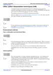
INTREPID User Manual
Library | Help | Top
Profile Editor (T17)
1
| Back |
Profile Editor (T17)
Top
The Profile Editor displays profile graphs of signal fields from line datasets and
enables you to edit this data. The profile graphs show fiducial value in the horizontal
dimension and signal values in the vertical dimension. The Profile Editor can display
profiles of a number of signal fields in separate graphs or superimposed.
You can apply calculations (filters) to signal fields before displaying them to assist
with detecting errors such as noise and spikes.
You can automatically find data points whose filtered or unfiltered signal values
match search criteria.
You can edit signal values by
•
Moving individual points in the profile using the mouse,
•
Selecting sets of adjacent points and cutting them (setting the signal values to
null) or replacing their signal values with values interpolated from neighbouring
points,
•
Finding signal values matching search criteria and cutting them (setting the
signal values to null) or replacing them with values interpolated from
neighbouring points.
The Profile Editor will only display data from a single traverse line at a time. You
can switch between traverse lines as required.
The Profile Editor horizontally synchronises all profiles displayed so that signal
values from the same data point are always vertically in line.
With V4.1, the concept of signal is extended to Tensor, Vector and Quaternion (or
Euler Angles). Some aspects of this extension remains in Beta as this treatment is
far from conventional signal processing concepts. If you wish to take advantage of
these extensions, you are advised to liase with Intrepid staff to get regular updates as
more functionality comes on-line.
Profile Editor concepts
The Profile Editor is a versatile tool for viewing and editing data and by nature has a
wide range of options. In order to use it effectively you will need to understand some
terms and concepts. The following glossary is organised in conceptual order rather
than alphabetically, so that by reading it you can develop an understanding of the
tool's operations.
signal field Field of a line dataset containing measured values (e.g., magnetic data)
from a survey (i.e., fields other than 'administrative' fields geographic location,
flight, line or fiducial number, etc.).
signal value Value of a signal field at a data point.
signal unit Measurement units of signal field data, e.g., nT for magnetic data.
Loaded signal field signal field that you have loaded into the Profile Editor so that
INTREPID displays its profile in the Profile Editor window.
Loaded signal field copies You can load several copies of the same signal field,
each with a different filter, including one copy without a filter.
Unfiltered signal field Loaded signal field to which no filter has been applied. To
edit a signal field you must load an unfiltered copy of it.
Library | Help | Top
© 2012 Intrepid Geophysics
| Back |
INTREPID User Manual
Library | Help | Top
Profile Editor (T17)
2
| Back |
Filtered signal field Loaded signal field to which you have applied a filter so that
INTREPID displays the results of the filter calculation in the Profile Editor
window.
Available filters The signal field filters available in the Profile Editor are all
designed for detecting noise and spikes in data. The filter results are typically
near 0 where the filter detects no noise and/or spikes.
The Profile Editor can apply Naudy, 4th Difference and Gradient filters.
For tensor signals, the filters currently available in this context are LaCoste RC
(IIR), Fraser low pass using a convolution, median.
For Quaternions, nothing is yet released for Beta.
Profile The graphic representation of a loaded signal field in the Profile Editor
window, with signal value or filtered signal value (vertical) plotted against
Fiducial value (horizontal).
Profile synchronisation If there are several loaded signal fields, INTREPID
synchronises their fiducial values so that all values from the same data point are
always in the same vertical line.
Current line The Profile Editor displays profile(s) for one traverse line at a time.
Navigate by You can use the Prev, Next and Go To navigation buttons to select lines
for viewing in the Profile Editor window or to indicate individual data points
within a line. You can specify the function of these buttons using the Navigate by
options in the Navigation Control area
Edit Field The unfiltered signal field to which you can make changes by direct
editing or using search and replace. INTREPID displays the Edit Field in blue at
the top of the data area. If you have loaded several unfiltered signal fields you can
specify which is to be the Edit Field.
Display options You can view the profiles
•
With or without data point markers, horizontal and vertical axes,
•
Using the horizontal and vertical scales of your choice,
•
In separate graphs, superimposed with independent scales or superimposed with
a common scale,
•
In any order you require.
Mouse mode You can use the mouse for a number of different Profile Editor
operations:
•
Zooming in and out,
•
Querying points in a profile to obtain signal and fiducial values,
•
Hanging signal values by relocating points in a profile and
•
Selecting sets of adjacent data points.
Select mouse mode using the Mouse Mode option buttons in the Command area of
the Profile Editor window.
Zoom You can horizontally expand sections of the profile graphs for a clearer view.
INTREPID retains the horizontal synchronisation by expanding all profiles.
Query Points If you have selected Query Points mouse mode, you can obtain reports
of signal and fiducial values by clicking the points you wish to query in the profile
graph.
Library | Help | Top
© 2012 Intrepid Geophysics
| Back |
INTREPID User Manual
Library | Help | Top
Profile Editor (T17)
3
| Back |
Find and replace You can search a filtered or unfiltered signal field for values
outside a range specified by you. When it finds a point matching your criteria
INTREPID can display a marker on the profile, then, if required,
•
Delete (set to null) the signal value in the Edit Field or
•
Replace the signal value in the Edit Field with a new value interpolated from the
signal values of neighbouring data points.
Search Profile The (unfiltered or filtered) loaded signal field that INTREPID
searches during a search or search and replace operation. The Search Profile can
be a filtered or unfiltered signal field.
Search domain You can specify the lines of the dataset to be searched. The set of
lines to be searched is the Search Domain.
The Profile Editor window
The Profile Editor window has a menu bar and three areas: the Command area, the
Navigation Control area and the Data area. The Data area can contain a number of
profiles, each in its own panel or superimposed on each other.
Using the Profile Editor
>> To use the Profile Editor:
1
If you wish to preselect the line dataset signal field to load as the first profile,
select it in the Project Manager window (See "Selecting datasets or files" in
INTREPID Old Project Manager (T01)).
2
Choose Profile Editor from the Edit menu of the Project Manager or use the
command pedit.exe.
INTREPID displays the Profile Editor window. If you preselected a signal field in
the Project Manager, go to step 4.
Library | Help | Top
3
Load a signal field that you wish to view and/or edit. Use Load signal from the
File menu. (See Specifying input and output files for detailed instructions.)
4
INTREPID will prompt you to specify the filter for the copy of the signal field you
are loading. Specify the filter if required and any parameters required. (See
Specifying input and output files for detailed instructions.)
© 2012 Intrepid Geophysics
| Back |
INTREPID User Manual
Library | Help | Top
Library | Help | Top
Profile Editor (T17)
4
| Back |
5
INTREPID will load the selected signal field and display the profile of the first
line. If you specify a compound data type, INTREPID loads and displays all of the
numeric components
6
If you wish to load more copies of signal fields, repeat steps 3–5 as often as
required.
© 2012 Intrepid Geophysics
| Back |
INTREPID User Manual
Library | Help | Top
Profile Editor (T17)
5
| Back |
7
Use the following operations to examine the data as required:
•
View the profiles of different lines using the Previous, Next and Go To buttons
(See Navigating the profile display);
•
Add or remove horizontal and/or vertical axes in the display (See Horizontal and
vertical axes);
•
Specify the vertical and/or horizontal scale (magnification) for the fully zoomedout view of the profiles (See Horizontal and vertical scale);
•
Zoom in on sections of the current line profile using the mouse in Zoom mouse
mode (See Enlarging and reducing (zooming) the profile display);
•
Use the horizontal scroll bar to view different sections of the current line profile
(See Scrolling along a profile display);
•
Display a marker for each data point (See Displaying data point markers);
•
Superimpose two or more loaded profiles instead of displaying them in separate
panels and specify independent or common scales for the superimposed display
(See Superimposed profiles view);
•
Change the display order of the loaded signal fields (See Setting the profile
display order);
•
View the signal value and other information for individual data points by clicking
the points required in Query Points mouse mode (See Querying points).
8
If you wish to edit a loaded signal field and have loaded more than one unfiltered
signal field, select the unfiltered signal field for editing (the Edit Field).
INTREPID displays the Edit Field in blue at the top of the window. See Choosing
the signal field you wish to edit.
9
Use the following operations to edit the data as required:
•
Individually change the value of individual signal values using the mouse (See
Editing individual data points);
•
Cut out sections of a profile and leave blank or interpolate across the gap using an
Akima spline (See Operations with sets of adjacent points);
•
Search for data outside an acceptable range in the signal values or filtered signal
values, and
•
Take note of it,
•
Cut it
•
Cut it and interpolate across the gap using an Akima spline.
See Find and Replace.
10 Repeat steps 7–9 as required.
11 If required, save the edited or filtered versions of the loaded signal fields with the
same field name or as a new field (Filtered signal fields are derived fields and
must have a new name). See Saving data from the Profile Editor.
12 If you wish to carry out further editing, close the loaded signal fields that you no
longer require and go to step 3. See Closing signal fields.
13 Exit from the Profile Editor by choosing Quit from the File menu.
Library | Help | Top
© 2012 Intrepid Geophysics
| Back |
INTREPID User Manual
Library | Help | Top
Profile Editor (T17)
6
| Back |
Specifying input and output files
To use the Profile Editor you will need to specify one or more signal fields from line
datasets to view or edit. You will commonly load the same field a number of times
with different filter options. After the editing process you may wish to save the edited
field either overwriting the previous version or creating a new field for the edited
data.
When loading and saving fields, use options from the File menu.
In each case INTREPID displays an Open or field selector or Save As dialog box. Use
the directory and file selector to specify the file you require. (See "Specifying input
and output files" in Introduction to INTREPID (R02) for information about specifying
files).
INTREPID identifies the fiducial field from the dataset aliases. The dataset must
have the following aliases identifying a appropriate fields.
Alias
Field File
Fiducial
Fiducial field
LineNumber
Line number field
See Datasets with no Fiducial field for information about that topic and "Vector
dataset field aliases" in INTREPID database, file and data structures (R05) for more
information about aliases.
Datasets with no Fiducial field
If a dataset has no fiducial field (i.e., if there is no Fiducial alias.) INTREPID will
automatically create a Sample Number field, numbering each data point in the order
it occurs in the dataset, starting at 1. INTREPID will use this field as the fiducial
field for all Profile Editor operations. At the end of the Profile Editor session with
this dataset, INTREPID will delete the Sample Number field.
See "Vector dataset field aliases" in INTREPID database, file and data structures
(R05) for more information about aliases.
Library | Help | Top
© 2012 Intrepid Geophysics
| Back |
INTREPID User Manual
Library | Help | Top
Profile Editor (T17)
7
| Back |
Loading signal fields and displaying profiles
>> To load and display a signal field
1
Choose Load Signal Field, Load Tensor field or Load Vector field from the File
menu.
(If you have not preselected the dataset in the Project Manager) INTREPID
displays a Load dialog box for selecting the dataset. Select the dataset you
require.
INTREPID displays a field selector dialog box for the data type you want to load.
2
Specify the signal field you require.
INTREPID displays a Filters dialog box. There are different Filters dialog boxes
for scalar and compound data types.
Select the Filter option you require then choose OK. See Available signal Field
Filters for information about the filters.
Library | Help | Top
© 2012 Intrepid Geophysics
| Back |
INTREPID User Manual
Library | Help | Top
3
Profile Editor (T17)
8
| Back |
If you selected a filter, INTREPID displays the parameters dialog box for the
filter.
Specify the parameters as required, then choose OK. See Available signal Field
Filters.
4
INTREPID displays the profile of the signal field.
You can load as many signal field copies as you can comfortably fit on the screen. The
following illustration shows a Profile Editor main window with five profiles.
Library | Help | Top
© 2012 Intrepid Geophysics
| Back |
INTREPID User Manual
Library | Help | Top
Profile Editor (T17)
9
| Back |
Available signal Field Filters
You can apply the following filters to signal fields before displaying their profiles. To
apply a filter, select the corresponding option in the Filters dialog box displayed when
you open a signal field (See Loading signal fields and displaying profiles).
Filters for scalar fields
None Use this to display a profile of the data itself with no filters applied (an
unfiltered signal field profile).
Naudy filter This detects sudden changes in data between neighbouring data points.
See "Naudy filter" in INTREPID spatial and time domain filters and
transformations (R13) for details.
4th Difference This calculates the 4th difference of the signal data. Non-zero 4th
difference results indicate sudden changes in the data. See the description of the
diffn() function in Section "INTREPID Functions" in INTREPID expressions
and functions (R12) for information about the 4th difference calculation
(diff4()).
Gradient This calculates the gradient of the signal field at each data point. A high
magnitude gradient indicates sudden changes which could be attributable to noise
or spikes.
Filters for compound fields
LaCosteRC, LaCosteCurvature See "Lacoste RC filter" in INTREPID spatial and
time domain filters and transformations (R13) for information
Local mean See "Local mean / median filters" in INTREPID spatial and time
domain filters and transformations (R13) for information
Marine acquisition data Contact our technical support service for information.
Sample interval Contact our technical support service for information.
Library | Help | Top
© 2012 Intrepid Geophysics
| Back |
INTREPID User Manual
Library | Help | Top
Profile Editor (T17)
10
| Back |
Saving data from the Profile Editor
After using the Profile Editor with the loaded fields you can save them, either
overwriting the previous versions or creating new fields for the edited data.
Note: You can save unfiltered fields, overwriting previous versions. A set of filter
results is a derived field and does not already exist in its present form in the dataset.
If you wish to save filter results you must use Save As and specify a name for the new
field.
>> To save loaded signal fields.
1
Choose Save or Save As from the File menu. Save will overwrite previous
versions of the fields and Save As will enable you to specify new field names.
INTREPID displays the Save signal Field or Save signal Field As dialog box.
2
Select fields to be saved by moving their names to the Selected list.
3
Library | Help | Top
•
To select a field for saving, select (click) its name in the Available list box so
that it is highlighted, then choose >> so that its name appears in the Selected
list box.
•
To deselect a field for saving, perform the reverse operation. Select (click) its
name in the Selected list box so that it is highlighted, then choose << so that
its name appears in the Available list box.
When you have finished selecting fields to be saved, choose OK. If you are using
Save As, INTREPID displays a Save As dialog box for each field, so that you can
specify its new name.
© 2012 Intrepid Geophysics
| Back |
INTREPID User Manual
Library | Help | Top
Profile Editor (T17)
11
| Back |
Closing signal fields
If you have finished with one or more loaded signal field copies or you wish to make
more room in the display, you can close the signal field(s).
>> To close loaded signal field copies
Library | Help | Top
1
Choose Close from the File menu. INTREPID displays the Close signal field
dialog box.
2
Select the fields to be closed by moving their names to the Close list box.
•
To select a field for closing, select (click) its name in the Open list box so that it is
highlighted, then choose >> so that its name appears in the Close list box.
•
To deselect a field for closing, perform the reverse operation. Select (click) its
name in the Close list box so that it is highlighted, then choose << so that its name
appears in the Open list box.
© 2012 Intrepid Geophysics
| Back |
INTREPID User Manual
Library | Help | Top
Profile Editor (T17)
12
| Back |
3
When you have finished selecting fields to be closed, choose OK.
•
For each signal field copy to be closed:
•
If you have applied a filter to it, INTREPID will close the field and remove it
from the display.
•
If you have not applied a filter to it, INTREPID displays the Do You Wish to
Save dialog box.
Select No, Save or Save As according to your requirements, then choose OK.
No INTREPID will close the field without saving it.
Save INTREPID will save the field with the same name, overwriting the previous
version, then close it.
Save As INTREPID displays a Save As dialog box for you to specify a new name for
the field being closed. After you have specified the name for the field, INTREPID
will save and close it.
If you choose Cancel, INTREPID will abandon closing the current signal field and
continue the closing procedure for any other selected fields.
Display options
The Profile Editor provides a range of display options. Use controls in the Profile
Editor window and options from the Layout and Window menus to control the
display.
Library | Help | Top
© 2012 Intrepid Geophysics
| Back |
INTREPID User Manual
Library | Help | Top
Profile Editor (T17)
13
| Back |
Setting the profile display order
You can specify the order in which INTREPID displays the profiles of the loaded
fields.
If you specify an unfiltered signal field as the first profile in the new order it will
automatically become the Edit Field. If you specify a filtered field as the first profile,
INTREPID will retain the current Edit Field. (See Choosing the signal field you wish
to edit for information about the Edit Field.
>> To specify the profile display order
1
Choose Set Display Order from the Window menu. INTREPID displays the
Profile Display Order dialog box.
2
Move the signal Field copy names to the New Order list box in the order required.
To move the name of the next signal Field copy, select (click) its name in the
Current Order list box so that it is highlighted, then choose >> so that its name
appears in the New Order list box.
If you make a mistake you can remove fields from the New Order list box, then
move fields to the list in the required order. To remove a field from the New
Order list box, perform the reverse operation. Select (click) its name in the New
Order list box so that it is highlighted, then choose << so that its name appears in
the Current Order list box.
3
When the New Order list box contains the fields in the desired order, choose OK,
INTREPID displays the signal field copies in the required order.
If you selected an unfiltered signal field as the first profile for display, it will
automatically become the new Edit Field.
Library | Help | Top
© 2012 Intrepid Geophysics
| Back |
INTREPID User Manual
Library | Help | Top
Profile Editor (T17)
14
| Back |
Horizontal and vertical axes
You can include horizontal and vertical axes in the profile display. The axes contain
tick marks and value labels. The horizontal axes show fiducial values, and the
vertical axes show signal values or the results of filters applied to signal values. If
you turn on axis display, INTREPID displays a separate axis for all displayed fields.
>> To turn horizontal and vertical axis display on and off
Use Show Vertical Axis and Show Horizontal Axis from the Layout menu. Each time
you choose one of these options, INTREPID turns the corresponding axis display on
or off. If the menu option has a tick, then the corresponding axis is displayed.
The following illustration shows a display of two profiles, each with their own set of
axes.
Library | Help | Top
© 2012 Intrepid Geophysics
| Back |
INTREPID User Manual
Library | Help | Top
Profile Editor (T17)
15
| Back |
Displaying data point markers
You can include a symbol G for each data point in the profile display.
>> To turn point display on or off
Use Show Points from the Layout menu. Each time you choose the option,
INTREPID turns point display on or off. The menu option has a tick when point
display is on.
The illustrations show Profile Editor windows with point display on.
Horizontal and vertical scale
INTREPID can automatically fit profile displays to the space available (automatic
scaling) or display profiles using a scale specified by you.
The Profile Editor always synchronises profile displays horizontally, so whenever you
specify the horizontal scale, it applies to all profiles.
You can specify a separate vertical scale for each profile displayed.
Notes:
•
INTREPID normally uses automatic scaling unless you specify otherwise.
•
The horizontal scale settings refer to the fully zoomed-out view of the profiles (See
Enlarging and reducing (zooming) the profile display for information about
zooming in and out).
•
If you use automatic horizontal scaling INTREPID displays each traverse line
with a different horizontal scale suitable for fitting it into the Profile Editor
window. If you specify a horizontal scale manually, INTREPID will use it for
displaying all lines, even if a whole line will not fit into the data area when fully
zoomed-out.
•
If you use automatic vertical scaling with a loaded signal field, INTREPID
displays each traverse line with a different vertical scale suitable for fitting it into
its panel in the Profile Editor window. If you zoom in, INTREPID will use a
vertical scale suitable for the data to be included in the display.
If you manually specify a vertical scale for a loaded signal field, INTREPID will use it
for displaying the profile for all lines or zoomed-in line sections.
Library | Help | Top
© 2012 Intrepid Geophysics
| Back |
INTREPID User Manual
Library | Help | Top
Profile Editor (T17)
16
| Back |
>> To specify horizontal scale
1
Choose Horizontal Scale from the Layout menu. INTREPID displays the
Horizontal Scale dialog box.
2
Select Automatic or Manual according to your requirements.
If you select Automatic, INTREPID displays the whole of each line in the Profile
Editor window, using a scale (fiducial numbers per display centimetre)
appropriate to each line. INTREPID is likely to display each line with a different
scale.
If you select Manual, enter the required scale (in fiducial numbers per display
centimetre) in the Scale text box.
3
Choose OK. INTREPID displays all profiles according to your specifications.
>> To specify vertical scale
1
Choose Vertical Scale from the Layout menu. INTREPID displays the Vertical
Scale dialog box.
2
For each loaded signal field, select the Automatic or Manual option according to
your requirements.
If you select Automatic, INTREPID will calculate a suitable scale (signal units per
display centimetre) for displaying the range of each line in the Profile Editor
window. INTREPID is likely to display each line with a different scale.
If you select Manual, enter the required scale (in signal units per display
centimetre) in the Scale text box. INTREPID will use this scale for this profile
with all lines, even if there is insufficient room in the display panel and high or
low values are not displayed.
3
Library | Help | Top
Choose OK. INTREPID displays the profiles according to your specifications.
© 2012 Intrepid Geophysics
| Back |
INTREPID User Manual
Library | Help | Top
Profile Editor (T17)
17
| Back |
Superimposed profiles view
You can superimpose profiles in the Profile Editor window. The profiles can have
•
Independent vertical scaling so that the profiles are displayed using the full
vertical space available in the Profile Editor window or
•
A common vertical scale so that you can compare the values quantitatively.
>> To superimpose the profiles in the window
1
If you will be using a common scale (see Step 4 below), ensure that all loaded
signal fields that you are superimposing have automatic vertical scaling (See
Horizontal and vertical scale for instructions).
2
Choose Superimpose Profiles from the Layout menu. INTREPID displays the
Superimpose Profiles dialog box.
3
Select the fields to be superimposed by moving their names to the Superimposed
list box.
To select a field for superimposing, select (click) its name in the Available fields
list box so that it is highlighted, then choose >> so that its name appears in the
Superimposed list box.
To deselect a field for superimposing, perform the reverse operation. Select (click)
its name in the Superimposed list box so that it is highlighted, then choose << so
that its name appears in the Available list box.
4
Library | Help | Top
When you have finished selecting fields to be superimposed, choose OK.
INTREPID displays the Superimpose Vertical Scaling Options dialog box.
© 2012 Intrepid Geophysics
| Back |
INTREPID User Manual
Library | Help | Top
5
Profile Editor (T17)
18
| Back |
Select the scaling option you require and choose OK.
Independent Scales Select this option if you wish to qualitatively compare the
profiles using the maximum data area space available. Each profile will have its
own scale appropriate to its range.
Common Scale Select this option if you are superimposing profiles with similar
signal value ranges and you wish to quantitatively compare them (e.g., compare
before and after a noise removal process). INTREPID selects and uses the same
vertical scale for all superimposed profiles.
The illustrations below show a Profile Editor window with superimposed profiles.
The first example shows independent scaling of a filtered with an unfiltered profile.
The second example shows a pair of related fields before and after a noise and spike
removal operation, superimposed using a common scale.
Navigating the profile display
The Profile Editor has a range of operations for viewing different parts of a dataset.
You can
•
View the profile of any line in the dataset;
•
Zoom in on any section of a profile;
•
Use the scroll bar to view different sections of a line's profile.
The Navigation Control area in the Profile Editor window contains the controls for
these operations.
Choosing a line or data point you wish to view
When you first load signal values from a dataset, INTREPID displays signal data
from the first line in the dataset. You can display data from other lines and locate
specific data points using the Navigate By options and the Next, Previous and Go To
command buttons.
The Profile Editor automatically sorts line numbers into ascending order, irrespective
of their actual order in the dataset.
Library | Help | Top
© 2012 Intrepid Geophysics
| Back |
INTREPID User Manual
Library | Help | Top
Profile Editor (T17)
19
| Back |
>> To view the Next or Previous line (according to line number)
1
Select Line from the Navigate By options in the Navigation Control area.
2
Use Next or Previous at the bottom of the Profile Editor window to view the next
or previous line respectively.
>> To view the line of your choice
1
Select Line from the Navigate By options in the Navigation Control area.
2
Choose Go To in the Profile Editor window. INTREPID displays the Select Line
dialog box.
3
Select (click) the number of the line you wish to view, then choose OK.
INTREPID displays the line.
>> To view a data point with a given fiducial number
Library | Help | Top
1
Display the profile of the line containing the data point you require (See
instructions immediately above )
2
Select Fid Within Line from the Navigate By options in the Navigation Control
area.
3
Choose Go To. INTREPID displays the Select Fiducial dialog box containing a list
of fiducial numbers in the current line.
4
Select (click) the fiducial number of the data point you wish to view, then choose
OK. INTREPID displays a marker G on the data point in each profile.
© 2012 Intrepid Geophysics
| Back |
INTREPID User Manual
Library | Help | Top
Profile Editor (T17)
20
| Back |
>> To view the Next or Previous data point (according to fiducial number)
1
Select Fid Within Line from the Navigate By options in the Navigation Control
area.
2
Use Next or Previous to view the next or previous data point respectively.
INTREPID displays a marker G on the data point in each profile.
Enlarging and reducing (zooming) the profile display
You can enlarge the profile display (zoom in) to display only a selected range of data
points, then zoom out again when you have finished.
Notes: (See Horizontal and vertical scale for information about scaling.)
•
Zooming in only involves selecting sets of data points. When you zoom the
display, INTREPID adjusts the horizontal scale so that the data points you
selected cover the whole width of the window, and vertical scale according to the
current vertical scale specifications.
•
When you zoom out, INTREPID displays the profiles using the horizontal scale
you have specified. If you have selected automatic horizontal scaling, INTREPID
displays each line so that it fills the available horizontal space in the data area.
•
As an alternative to zooming, you can set the magnification manually by setting
the horizontal scale for the profile display.
>> To zoom in on a set of data points
Library | Help | Top
1
Select Zoom from the Mouse Mode option buttons.
2
Move the mouse pointer to one end of the range of data points that you wish to
enlarge. Hold down the left button and drag across to the other end of the range.
INTREPID displays a pair of light blue vertical bars defining the range you select.
3
Release the mouse button.
© 2012 Intrepid Geophysics
| Back |
INTREPID User Manual
Library | Help | Top
Profile Editor (T17)
21
| Back |
INTREPID will enlarge the display to show only those points you selected.
>> To zoom out
Choose Zoom Out from the Layout menu OR
Click anywhere in the display with the right mouse button.
INTREPID displays the profiles using the current horizontal and vertical scale
settings.
Scrolling along a profile display
When you enlarge (zoom) a profile display or manually set the horizontal scale, only
part of it may be visible. You can examine other sets of data points within the current
line using the scroll bar at the bottom of the display.
>> To scroll the display horizontally
You can perform any of the following operations.
Library | Help | Top
•
Click the scroll arrows to shift the display one data point at a time.
•
Click the scroll box channel to shift the display to the next or previous set of data
points that will fit on the screen.
•
Drag the scroll box to a position in the scroll bar corresponding to the data points
you wish to view.
© 2012 Intrepid Geophysics
| Back |
INTREPID User Manual
Library | Help | Top
Profile Editor (T17)
22
| Back |
Querying points
You can obtain information about (query) an individual data point by clicking the
point in the Profile Editor window. If you query a point INTREPID displays its
fiducial number and the value of the signal field.
Note: You can also view a list of a set of adjacent data points containing fiducial and
signal values. See Listing selected points for details.
>> To query a point
Library | Help | Top
1
Display the line containing the point(s) you wish to query. Zoom in if required.
(See Navigating the profile display and Enlarging and reducing (zooming) the
profile display)
2
Select Query Points from the Mouse Mode option buttons.
3
Click the point you wish to query. INTREPID displays its fiducial number and
the signal value in that profile.
4
Repeat step 3 or steps 1–3 as required.
© 2012 Intrepid Geophysics
| Back |
INTREPID User Manual
Library | Help | Top
Profile Editor (T17)
23
| Back |
Choosing the signal field you wish to edit
The Profile Editor edits one unfiltered signal field at a time. If you have loaded more
than one unfiltered field you will need to specify which is to have the focus for editing.
This is called the Edit Field and its profile appears in blue at the top of the data area.
INTREPID can perform the following edit operations on the Edit Field as required:
•
Move Points (See Editing individual data points);
•
Select Points then Cut or Interpolate (See Operations with sets of adjacent
points);
•
Search for signal values then Cut or Interpolate (See Find and Replace).
If you have only loaded filtered signal fields then you cannot have an Edit Field and
therefore cannot perform the above operations.
The Edit Field is different from the Search Profile. The Search Profile is the field that
INTREPID searches during a search or search and replace operation. The Search
Profile can be an unfiltered or filtered field. It is common for the Search Profile to be
a filtered copy of the Edit Field, but not essential. See Find and Replace for details
about the search operation.
When you rearrange the order of the profiles on the screen you may automatically
change to a different Edit Field (See Setting the profile display order).
>> To select the Edit Field
1
Choose Select Edit Field from the Window menu.
INTREPID displays the Select the Edit Field dialog box.
Select (click) the name of the field you require, then choose OK. INTREPID will
make this field the Edit Field and display its profile in blue at the top of the data
area.
Undo
INTREPID records all editing operations that you carry out. You can undo them,
starting at the most recent operation.
Library | Help | Top
© 2012 Intrepid Geophysics
| Back |
INTREPID User Manual
Library | Help | Top
Profile Editor (T17)
24
| Back |
>> To undo the most recent operation (or the previous operation in the Profile
Editor operation history),
Choose Undo from the Edit menu.
Editing individual data points
You can change an individual signal value by moving a data point in the Edit Field's
profile to a new vertical position using the mouse.
>> To edit a data point,
Library | Help | Top
1
Select the loaded field you require as the Edit Field. Display the line containing
the point(s) you wish to query and zoom in if required.
2
Turn on point display if required (See Displaying data point markers for
instructions).
3
Select Move Points from the Mouse Mode option buttons.
4
Click the vertical position corresponding to the new value of the data point you
wish to change. INTREPID will move the data point to the new position,
changing its signal value accordingly. If there is no data point directly above or
below the position that you click, INTREPID will move the nearest data point up
or down to the level you specify.
5
Repeat step 4 or 1–4 as often as required.
6
When you have finished editing points, change the mouse mode to Query Points or
Zoom in case you unintentionally edit some more points.
© 2012 Intrepid Geophysics
| Back |
INTREPID User Manual
Library | Help | Top
Profile Editor (T17)
25
| Back |
Operations with sets of adjacent points
You can select sets of adjacent data points in the profile display and
•
Cut them from the Edit Field (set the Edit Field signal values to null),
•
Replace them with a smooth interpolation based on neighbouring points outside
the selection,
•
View a complete list of the points with field values.
The Cut, Interpolate and List commands are available in the Edit menu.
Library | Help | Top
© 2012 Intrepid Geophysics
| Back |
INTREPID User Manual
Library | Help | Top
Profile Editor (T17)
26
| Back |
Selecting a set of adjacent points
>> To select a set of adjacent data points
1
Select the loaded field you require as the Edit Field. Display the line containing
the point(s) you wish to select. Zoom in if required.
2
Select Select Points from the Mouse Mode options.
3
Move the mouse pointer to one end of the range of data points that you wish to
select. Hold down the left button and drag across to the other end of the range.
INTREPID displays a pair of light blue vertical bars defining the range you select.
(See Enlarging and reducing (zooming) the profile display for an illustration of
this process.)
4
Release the mouse button. INTREPID displays the selected points in red.
Cutting selected points
If you have selected a set of adjacent data points you can cut them. Cutting points
using the Profile Editor really means setting their signal values in the Edit Field to
null. After the cut operation the data points and the values of all of their other fields
still exist in their original form.
>> To cut a set of points (set Edit Field signal values to null
Library | Help | Top
1
Select the points required (See Selecting a set of adjacent points).
2
Choose Cut from the Edit menu.
© 2012 Intrepid Geophysics
| Back |
INTREPID User Manual
Library | Help | Top
Profile Editor (T17)
27
| Back |
Replacing selected points with interpolated values
If you have selected a set of adjacent data points you can replace their signal values
with new values interpolated from the signal values on either side of the selection.
INTREPID uses an Akima spline and the three neighbouring points on each side to
calculate the interpolated values.
>> To replace a set of points with interpolated values
1
Select the points required (See Selecting a set of adjacent points).
2
Choose Interpolate from the Edit menu.
These illustrations show the result of an interpolate operation.
Listing selected points
If you have selected a set of adjacent data points you can display a list of them. The
list has a line for each data point and includes the fiducial value and the value of all
loaded signal fields, set out in columns .
If you are using INTREPID under Unix, it displays the list in the background
window.
If you are using INTREPID under Windows and wish to use this feature, contact our
technical support service for advice.
>> To list the selected points
Library | Help | Top
1
Select the points required (See Selecting a set of adjacent points).
2
Choose List Selected Points from the Edit menu.
© 2012 Intrepid Geophysics
| Back |
INTREPID User Manual
Library | Help | Top
Profile Editor (T17)
28
| Back |
Find and Replace
You can search a filtered or unfiltered field for data points that have signal values or
filter results outside a range set by you.
If required you can cut the matching signal values in the Edit Field (i.e., set them to
null) or replace them with new signal values interpolated from neighbouring data
points.
>> To perform a search operation
1
Set the Edit Field (See Choosing the signal field you wish to edit).
2
Choose Find from the Edit menu.
INTREPID displays the Find dialog box.
3
Specify the Search Profile (the signal field to be searched). See Search Profile for
instruction.
INTREPID displays the name of the Search Profile you have selected.
Library | Help | Top
© 2012 Intrepid Geophysics
| Back |
INTREPID User Manual
Library | Help | Top
4
Profile Editor (T17)
29
| Back |
Specify the Search Domain (the set of lines that you wish to search). See Search
domain for instruction.
INTREPID displays the Search Domain you have selected.
5
If the Search Profile is the result of a 4th Difference filter, specify the Tolerance
value.
Tolerance INTREPID finds 4th Difference values with magnitude greater than the
Tolerance. If the Search Profile is an unfiltered field or filter results other than
4th difference, enter the Minimum and Maximum values of the search range.
Minimum / Maximum INTREPID finds values outside the range defined by these
values.
6
Specify the action to be taken on data points matching the search condition
(values in the Search Profile and Search Domain that are outside the tolerance or
search range). Choose None, Cut or Interpolate from the Action options.
None INTREPID will find data points matching the search condition but leave their
signal values unchanged.
Cut INTREPID will find data points matching the search condition but set their
signal values to null.
Interpolate INTREPID will find data points matching the search condition and
interpolate a new signal value for them using an Akima spline based on the signal
values of the three neighbouring data points on each side.
7
Specify whether you wish to
•
Use a Confirm dialog box to apply the search or search and replace operation
point by point or line by line or
•
Automatically apply the search or search and replace operation to the whole
search domain.
Select Confirm Changes or Apply to All from the Control options.
Library | Help | Top
© 2012 Intrepid Geophysics
| Back |
INTREPID User Manual
Library | Help | Top
8
Profile Editor (T17)
30
| Back |
When you have set the parameters, choose Apply.
If the Search Profile is the result of a 4th Difference filter, INTREPID displays
the 4th Difference Search Condition dialog box. Otherwise go to the next step.
Select Standard 4th Difference Noise Detection or Single Point Spike Detection
according to your requirements, then choose OK.
Standard 4th Difference Noise Detection If you select this option, INTREPID
will search the 4th difference filter results.
Single Point Spike Detection If you select this option INTREPID will search the
4th difference filter results and perform additional tests to detect single point
spikes.
9
If you selected Apply to All from the Control options, INTREPID will perform the
Find and any replace operation on all matching data points in the search domain.
Go to step 14.
If you selected Confirm Changes from the Control option buttons, INTREPID will
locate the first matching data point, indicate it with a red marker G, then display
the Confirm Action dialog box.
10 Select Point, Line or All from the Apply To option buttons. These options
determine how much of the Search Domain you wish to search and cut or
interpolate as required next time you choose the Edit or Ignore button.
Point If you select Point, INTREPID will carry out the cut or interpolate operation if
specified on the current data point, then find the next point matching the search
condition.
Line If you select Line, INTREPID will carry out the cut or interpolate operation if
specified on the current data point and on the rest of the points in the current line
of the search domain, then find the next point matching the search condition in
the next line.
Library | Help | Top
© 2012 Intrepid Geophysics
| Back |
INTREPID User Manual
Library | Help | Top
Profile Editor (T17)
31
| Back |
All If you select All, INTREPID will carry out the cut or interpolate operation if
specified on the current data point and on the rest of the points in the search
domain.
11 If you wish to continue the search process choose Edit or Ignore.
Edit If you choose Edit and you have specified a cut or interpolate operation
INTREPID will carry it out on the data specified by the selected Apply To option
(see previous step), then search for the next point matching the search condition.
Ignore If you choose Ignore INTREPID will skip over the data specified by the
selected Apply To option (see previous step), then search for the next point
matching the search condition.
As you step through the Search Domain INTREPID displays the progressive
result and indicates the current data point.
12 Repeat steps 10–11 as required.
13 If you wish to terminate the current search before you have reached the end of the
Search Domain, choose Close.
14 Repeat steps 3–13 as required.
Library | Help | Top
© 2012 Intrepid Geophysics
| Back |
INTREPID User Manual
Library | Help | Top
Profile Editor (T17)
32
| Back |
15 Choose Close in the Find dialog box.
The following illustration shows a profile of a signal field containing noise and a
profile of a version of the signal field from which the noise has been automatically
removed.
Library | Help | Top
© 2012 Intrepid Geophysics
| Back |
INTREPID User Manual
Library | Help | Top
Profile Editor (T17)
33
| Back |
Search domain
When you are specifying a search or search and replace operation, you need to specify
which lines from the dataset to search. This selection is called the search domain.
>> To specify the search domain
This operation always takes place from the Find dialog box. See Find and Replace for
a full description.
1
Choose Search Domain.
INTREPID displays the Select Search Domain dialog box.
The Selected Lines list box shows a list of the lines that are included in the Search
Domain and the Loaded Lines list box shows a list of lines that are not part of the
Search Domain.
2
Move the line numbers between the Loaded Lines and Selected Lines list boxes as
required.
To move a line number to the other list select (click) it so that it is highlighted,
then choose >> or <<.
To select all lines, choose All >>.
To unselect all lines, choose All <<.
The following illustration shows a search domain containing only lines 2742 and
2751.
3
When you have completed your line selection, choose OK.
INTREPID displays a summary of the Search Domain in the Find dialog box.
Library | Help | Top
© 2012 Intrepid Geophysics
| Back |
INTREPID User Manual
Library | Help | Top
Profile Editor (T17)
34
| Back |
Search Profile
When you are specifying a search or search and replace operation, you need to
specify which signal field or filtered signal field to search. This selection is called
the Search Profile.
The Search Profile is different from the Edit Field. The Edit Field is always an
unfiltered signal field. All editing is performed on the Edit Field. It is common
but not essential for the Search Profile to be a filtered copy of the Edit Field. See
Choosing the signal field you wish to edit for details.
>> To specify the Search Profile
This operation always takes place from the Find dialog box. See Find and Replace
for a full description.
1
Choose Search Profile. INTREPID displays the Select Search Profile dialog box.
2
Select (click) the signal field or filtered signal field that you wish to search so that
it is highlighted. Choose OK.
INTREPID will show the Search Profile field name in the Search dialog box.
Help
Exit from the Profile Editor
>> To exit from the Profile Editor
Choose Quit from the File menu.
Library | Help | Top
© 2012 Intrepid Geophysics
| Back |
INTREPID User Manual
Library | Help | Top
Profile Editor (T17)
35
| Back |
Audit trail files
You can save an audit trail file with a record of the changes made to the dataset. This
provides part of the processing history of the dataset. Audit trail files are a variety of
task specification file and have the extension .job. The current version of
INTREPID cannot use audit trail files in batch mode or for loading specifications into
the Profile Editor tool.
>> To create an audit trail file with the Profile Editor tool
1
Perform all editing operations.
2
Choose Save Options from the File menu. Specify an audit trail file (INTREPID
will add the extension .job) INTREPID will create the file with a record of the
editing processes performed.
For full instructions on creating and editing task specification files see INTREPID
task specification (.job) files (R06).
Audit trail file example
Here is an example of an Profile Editor audit trail file.
Process Begin
Name = ProfileEdit
Parameters Begin
ZFilter Begin
Type = Naudy
Tolerance = 0.1
Wavelength = 5.0
ZFilter End
EditDelta Begin
Type = Interpolate
Group = 1
FromRow = 370
ToRow = 394
EditDelta End
EditDelta Begin
Type = Cut
Group = 3
FromRow = 11
ToRow = 11
EditDelta End
EditDelta Begin
Type = Interpolate
Group = 3
FromRow = 23
ToRow = 23
EditDelta End
Parameters End
Process End
Library | Help | Top
© 2012 Intrepid Geophysics
| Back |
INTREPID User Manual
Library | Help | Top
Profile Editor (T17)
36
| Back |
Frequently asked questions
Q : Is the 4th diff operator in Profile Editor the same as the DIFF4 operator in
the spreadsheet?
The 4th diff operator in profile editor is the same as the NDIFF4 operator in the
spreadsheet. This operator normalises the output, dividing by a factor that reduces
the amplitude of the 4th difference.
Q : I have some old bathymetry data with some sudden steps in the data. Can
I easily remove them?
The Profile Editor has a simple interactive step removal filter designed for this very
purpose. It is located under the 'Supervised step correction' option.
Library | Help | Top
© 2012 Intrepid Geophysics
| Back |