1
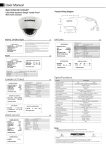
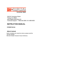
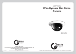
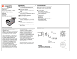
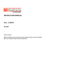
PRECAUTIONS
5436 W Crenshaw Street
Tampa, FL 33634
www.digital-watchdog.com
INSTRUCTION MANUAL
B1365T
■ Do not open or modify
Do not open the case except during maintenance and
installation, as it may be dangerous and cause damages.
■ Do not put objects inside the unit
Make sure that no metal objects or flammable substances
get inside the camera. It could cause fire, short-circuits or
damages.
■ Be careful when handling the unit
To prevent damage, do not drop the camera or subject it to
strong shock or vibration.
About manual
■ Install away from electric or magnetic fields
Before installing and using the camera, please read this
manual carefully.
Be sure to keep it handy for future reference.
■ Protect from humidity and dust
■ Protect from high temperature
Be careful when installing close to the ceiling , in a kitchen
or boiler room, as the temperature may rise to high levels.
TROUBLESHOOTING
Before sending the camera out for repair, check the
items below. If the problem persists after checking
these items, contact your service center.
■ If no image appears.
Is the coaxial cable attached securely?
Are the power and voltage normal?
Has the iris of the lens inside the camera been
adjusted correctly (with the level volume) ?
Is there adequate illumination?
■ If the image is unclear
Is the lens in focus?
Is the lens dirty?
Dirt of fingerprints on the lens can adversely
affect the images.
Gently wipe any dirt or fingerprints off the lens
with a soft cloth or lens cleaning paper and cleaning
fluid (commercially available).
Is the monitor adjusted correctly?
■ Cleaning
Dirt can be removed from the case only by wiping it with
a soft cloth moistened with a soft detergent solution.
■ Mounting Surface
The mounting surface material must be strong enough to
support the camera.
WARRANTY INFORMATION
Digital Watchdog (referred to as “the Warrantor”) warrants
the Camera Series against defects in materials or
workmanship as follows:
LABOR: For the initial five (5) years from the date of original
purchase, if the camera is determined to be defective, the
Warrantor will repair or replace the unit, with
new or refurbished product at its option, at no charge.
PARTS: In addition, the Warrantor will supply replacement
parts for the initial five (5) years. To obtain warranty or out
of warranty service, please contact a Technical Support
Representative at 1-866-446-3595 Monday through Friday
from 9:00 AM to 5:00 PM Eastern.
A purchase receipt or other proof of the date of the original
purchase is required before warranty service is rendered.
This warranty only covers failures due to defects in
materials and workmanship which arise during normal use.
This warranty does not cover damage which occurs in
shipment or failures which are caused by products not
supplied by the Warrantor or failures which result from
accident, misuse, abuse, neglect, mishandling,
misapplication, alteration, modification, faulty installation,
set-up adjustments, improper antenna, inadequate signal
pickup, maladjustment of consumer controls, improper
operation, power line surge, improper voltage supply,
lightning damage, rental use of the product or service by
anyone other than an authorized repair facility or damage
that is attributable to acts of God.
DIMENSION (mm)
LIMITS AND EXCLUSIONS
There are no express warranties except as listed above.
The Warrantor will not be liable for incidental or
consequential damages (including,
(including without limitation,
limitation
damage to recording media) resulting from the use of
these products, or arising out of any breach of the
warranty. All express and implied warranties, including
the warranties of merchantability and fitness for
particular purpose, are limited to the applicable warranty
period set forth above.
Some states do not allow the exclusion or limitation of
incidental or consequential damages, or limitations on
how long an implied warranty lasts, so the above
exclusions or limitations may not apply to you.
This warranty gives you specific legal rights and you may
also have other rights that vary from state to state.
If the problem is not handled to your satisfaction, then
write to the Address above.
Service calls which do not involve defective materials or
workmanship as determined by the Warrantor, in its sole
discretion, are not covered. Costs of such service calls
are the responsibility of the purchaser.
WARNING:
TO PREVENT THE RISK OF FIRE OR ELECTRIC
SHOCK, DO NOT EXPOSE THIS APPLIANCE TO
RAIN OR MOISTURE.
CAMERA SETTINGS
CONNECTION
● DIP switch setting
1
2
ON
NTSC
x
OFF
PAL
x
■ OSD MENU CONTROL
• CENTER KEY
- Used to access menu mode, Also used
to confirm the setting
• UP/DOWN KEY - Used to choose the desired menu
selection.
• LEFT/RIGHT KEY - Used to choose the desired menu
feature adjustment.
■ OSD MUNU ENTER/EXIT
A. OSD MENU ENTER
• Pushing Center Key for 3 seconds.
B. OSD MENU EXIT
• Press EXIT Menu from Main Menu
• If Pressing Set Key for 3 seconds from Main Menu
appears
In this case, just press Set Key.
C. 'SAVE' and 'QUIT'
• Left or Right Key - Selecting Menu
• Up or Down Key - Returning to Menu
1. Press the SET key to access the main setup mode.
2. Select the desired feature using the UP or Down key.
3. Change the status of the selected feature using the LEFT
or RIGHT key.
■ MAIN MENU
A. SETUP ID
• DISPLAY ID
- ON :The ID name will displayed in the monitor.
- OFF : The name will not displayed in the monitor.
• CAMERA ID : You can be written to 12 characteristic.
• ID POSITION : Select on screen position of
the camera ID.
B. LENS
• MANUAL : Use When using Manual lens.
• DC : You can control the brightness of the screen and
adjust the desired DC level from 10 to -42.
C. WDR
•EXPO(EXPOSURE): It has the effect of lightening or
darkening the picture
•WDR (Wide Dynamic Range) : You can adjust
D. WB CONTROL
• ATW (Auto Tracking White Balance) : The camera
automatically control the white balance in any environment.
• AWB (Auto White Balance) : The white balance is
automatically adjusted in a specific environment.
• MANUAL : Users can adjust the colors by adding or
reducing the WB level. You can adjust the desired
WB level from 2,500K to 9,500K
E. AGC
• ON : Activate automatic gain control feature.
You can adjust the desired AGC level from 0 to 36dB.
• OFF : Deactivate automatic gain control feature.
F. LOW LIGHT
• SLOW SHUTTER : Control Image brightness by adjusting
shutter speed
- AGC : shutter speed setting( Range 28 to 42)
- MAX FIELD : Shutter open from Min. x2 to Max. x32
filed accumulation period.
• B&W SS (Black and White Slow Shutter)
• GAIN : To get brighter picture.
G. SYNC
• INTERNAL : Internal synchronization
• LINE LOCK : Phase adjustment may be necessary in
multiple camera installations to prevent picture roll
when switching between cameras
H.RS485
• CAMERA # : Selectable from 1 to 255
(Note : Pelco D is the default)
I. DAY/NIGHT
• AUTO : For automatic switchover from day mode to night
( Note : This setting is dependent on the AGC setting.)
• B/W : To keep a B/W image at all times
• COLOR : To keep a color image at all times
CAUTION :
Check for polarity when using a DC 12V / AC 24V.
CAMERA SETING ANGLE
※ ATTENTION
1. Do not rotate ① more than 360˚.
2. Do not twist ② many times unnecessarily.
CONTROL BOARD & LENS ADJUSTMENT
• CDS : External input signal control
J. EXIT MENU
• EXIT NO CHANGES : No change
• SAVE NEW AND EXIT : Save change
• RESTORE FACTORY SETTINGS : Factory default
• SW REV
K. PREVIOUS PAGE
• PREVIOUS PAGE : Return page
1
2
OSD controller
Video Test Output
Connector
1. Rotate Zoom lever with the supplied Allen key.
2. Rotate Focus lever with the supplied Allen key.
FUNCTIONAL OF CONTROL BOARD
[1]Functional control of O.S.D(On Screen Display)
[2]Functional of VIDEO OUT(2ND)
B1365T
Model
Camera TYPE
Color/B/W
Mount
Device
Image
Pixels-Total
Pixels-Effective
System
Scanning
Horizontal Frequency Internal Mode
Vertical Frequency Internal Mode
F1.2
Min. Scene Illumination
WDR Level
WDR
Slow Shutter
OSD Controls
AGC
AWB
Focal Length
Lens
Horizontal
Resolution
VBS 1.0Vp-p
Video Output
S/N Ratio
S/N Ratio
Environmental Conditions Operating Temperature
Humidity
Power Requirement
Power
Power Consumption
Physical Specification
Certifications
Dimensions(H x L)
Nema Type
Weight
CE, FCC, RoHS
PIXIM Bullet Camera
3D Bracket
1/3" PIXIM
742(H) x 552(V)
720(H) x 540(V)
525 line, 2:1Interlace
15,734 Hz
59.94 Hz
0.08 Lux [TDN 0.01 Lux]
-20 to 20
2X ~ 32X
ON / OFF (Gain Adjust)
ATW / AWC / Manual
Pan-Focus Lens [3.3 ~ 12mm (3.6x Optical)]
540 TV Lines [at TDN (B/W) :570 TV Lines]
VBS 1.0Vp-p (75 Load)
48dB
-10℃ ~ +55℃(14℉ ~ 131℉)
Less than 90%
12VDC/24VAC
12VDC: 310mA, 1A (Heater ON)
24VDC: 225mA, 500mA (Heater ON)
85.4 x 231.5mm
IP66
2,2 lbs
Certified