1
Engineering Data
ED 15102-4
Group: Controls
Part Number: ED 15102
Date: May 2012
Supersedes: ED15102-3
MicroTech® II
Maverick™ II Rooftop Unit Controller
Protocol Information
BACnet® Networks
LonWorks® Networks
MPS
© 2012 Daikin
Daikin Commercial Rooftop System
Table of Contents
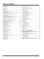
Table of Contents ........................................................................... 2
Revision History........................................................................................... 3
Software Revision ........................................................................................ 3
Reference Documents................................................................................... 3
Notice ........................................................................................................... 3
Limited Warranty ......................................................................................... 4
Introduction .................................................................................... 5
MPS Rooftop Unit Controller Data Points ................................................... 5
Protocol Definitions ..................................................................................... 5
Basic Protocol Information ............................................................ 6
Setting MPS Rooftop Unit Controller Communication Parameters .............. 6
BACnet Networks ........................................................................................ 6
MPS Rooftop Unit Controller Device Object ............................................... 7
BACnet Network Integration ........................................................................ 8
LONWORKS Networks ................................................................................ 10
Minimum Integration Requirements ............................................ 16
Set up the MPS Rooftop Unit Controller for Network Control ................... 16
Network Off ............................................................................................... 16
Network Occupancy Scheduling ................................................................ 16
Alarms ........................................................................................................ 17
MPS Rooftop Unit Controller Sequence of Operation ................................ 17
Comprehensive Data Point Tables .............................................. 18
BACnet Standard Objects........................................................................... 18
LONWORKS Variables ................................................................................ 20
Detailed Data Point Information .................................................. 23
Application Mode ....................................................................................... 23
Application Version ................................................................................... 24
Building Static Pressure ............................................................................. 24
Building Static Pressure Input .................................................................... 25
Building Static Pressure Setpoint ............................................................... 25
Cooling Capacity ........................................................................................ 26
Cooling Status ............................................................................................ 26
Current Alarm ............................................................................................ 27
Discharge Air Cooling Setpoint.................................................................. 28
Discharge Air Heating Setpoint .................................................................. 28
Discharge Air Temperature ........................................................................ 29
Discharge Fan Capacity .............................................................................. 29
Duct Static Pressure.................................................................................... 29
Duct Static Pressure Setpoint ..................................................................... 30
Economizer Enable..................................................................................... 30
Economizer Status ...................................................................................... 31
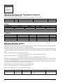
Effective Discharge Air Temperature Setpoint ........................................... 32
Effective Setpoint Output ........................................................................... 32
Emergency Override................................................................................... 33
Exhaust Fan Capacity ................................................................................. 34
Exhaust Fan Capacity Input ........................................................................ 34
Exhaust Fan Status ..................................................................................... 35
Heating Status ............................................................................................ 35
Local OA Temperature ............................................................................... 36
2
Local Space Temperature ........................................................................... 36
Maximum Discharge Air Heating Setpoint ................................................ 37
Daikin RTU Unit State ............................................................................ 37
Minimum Discharge Air Cooling Setpoint ................................................. 38
Minimum Send Time ................................................................................. 38
Occupancy.................................................................................................. 39
Occupancy Mode ....................................................................................... 39
Occupancy Scheduler Input ........................................................................ 40
Occupied Cooling Setpoint......................................................................... 42
Occupied Heating Setpoint ......................................................................... 42
Outdoor Air Damper Minimum Position Input........................................... 43
Outdoor Air Damper Position..................................................................... 43
Outdoor Air Temperature ........................................................................... 44
Outdoor Air Temperature Input .................................................................. 44
Primary Cool Enable .................................................................................. 45
Primary Heat Enable .................................................................................. 46
Primary Heating Capacity .......................................................................... 47
Receive Heartbeat ...................................................................................... 47
Remote Discharge Fan Capacity Setpoint .................................................. 47
Return Air Temperature ............................................................................. 48
Send Heartbeat ........................................................................................... 48
Space CO2 .................................................................................................. 48
Space IAQ Input ......................................................................................... 49
Space Temperature ..................................................................................... 49
Space Temperature Input............................................................................ 50
Temperature Setpoint Input ........................................................................ 50
Unit State - LONWORKS ............................................................................ 50
Unit Status .................................................................................................. 52
Unoccupied Cooling Setpoint..................................................................... 52
Unoccupied Heating Setpoint ..................................................................... 53
Alarms .......................................................................................... 54
Alarm Classes ............................................................................................ 54
Alarm Monitoring ...................................................................................... 54
Alarm Clearing ........................................................................................... 55
Objects ....................................................................................................... 55
Appendix A: Protocol Implementation
Conformance Statement (PICS) .................................................. 57
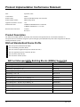
Protocol Implementation Conformance Statement.................... 58
Product Description .................................................................................... 58
BACnet Standardized Device Profile ......................................................... 58
BACnet Interoperability Building Blocks (BIBBs) Supported ................... 58
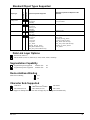
Standard Object Types Supported .............................................................. 59
Data Link Layer Options ............................................................................ 59
Segmentation Capability ............................................................................ 59
Device Address Binding............................................................................. 59
Character Sets Supported ........................................................................... 59
Appendix B: Subnet Mask - CIDR Conversion Table ................. 60
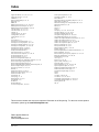
Index ............................................................................................. 61
ED 15102-4
Revision History
ED15102
ED15102-1
June 2007
September 2008
ED15102-2
ED15102-3
November, 2009
April, 2011
ED15102-4
May 2012
Initial release.
Relocated Occ Schedule point to Occupancy section in BACnet and LON data tables.
Added Discharge Air Heating Setpoint (nviDAHtSP or AV18).
Added Maximum Discharge Air Heating Setpoint (nciDAHtSP or AV19)
Changed Occupancy in the BACnet table from an AV to MV. It was labeled incorrectly in the table.
Changed the default for the Occupied Cooling Setpoint from 75°F to 72°F.
Changed the default for the Occupied Heating Setpoint from 70°F to 68°F.
Removed Effective DAT Setpoint from BACnet table on p.19
Corrected Max Info Frames and Max Master parameters in Table 1. Updated application code to v1.08
on pp. 3 and 58.
Updated Daikin logo and references. Clarified Application Mode description.
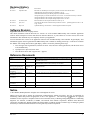
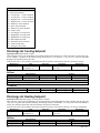
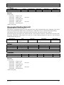
Software Revision
Keypad Menu Path Hidden.Unit Config/App Version=
This edition documents Network Protocols for version 1.08 of the standard MPS Rooftop Unit Controller application
software and all subsequent versions until otherwise indicated. However, if your software is of a later version, some of the
information in this document may not completely describe your application.
You can determine the revision of the application software from the MPS Rooftop Unit Controller keypad display. This
information appears on the keypad when the MPS Rooftop Unit Controller is initially powered up. It can also be found on
the “hidden” Unit Config menu of the keypad display, which is accessed by following these steps:
1.
Press the upper left keypad button (with the left arrow icon) and lower left keypad button (with the down arrow
icon) simultaneously.
2.
If prompted for a password, enter: 4545.
3.
Press the down arrow until “App Version =” appears.
Reference Documents
Daikin
Company
Number
OM 843
Daikin
UM 855
American Society of
Heating, Refrigerating and
Air-Conditioning Engineers
LonMark Interoperability
Association
LonMark Interoperability
Association
LonMark Interoperability
Association
ANSI/
ASHRAE 1352001
078-0014-01E
LonMark Interoperability
Association
Echelon Corporation
Title
Source
MicroTech II® Commercial Packaged Rooftop Unit Controls, MPS Unit www.DaikinApplied.com
Controller (DAC, SCC)
MicroTech II BACnet® Communication Module Configuration Tool
www.DaikinApplied.com
for Daikin MPS (Maverick II™) Rooftop Unit Controllers
BACnet A Data Communication Protocol for Building Automation and
www.ashrae.org
Control Networks
LonMark® Layers 1-6 Interoperability Guidelines, Version 3.4
www.lonmark.org
078-0120-01E
LonMark Application Layer Interoperability Guidelines, Version 3.4
www.lonmark.org
8500_10
LonMark Functional Profile: Space Comfort Controller, Version 1.0
www.lonmark.org
8600_10
LonMark Functional Profile: Discharge Air Controller, Version
www.lonmark.org
078-0156-01G
LonWorks FTT-10A Free Topology Transceiver Users Guide
www.echelon.com
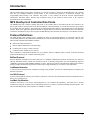
Notice
© 2012 Daikin, Minneapolis MN. All rights reserved throughout the world
Daikin reserves the right to change any information contained herein without prior notice. The user is responsible for
determining whether this product is appropriate for his or her application. The following are trademarks or registered
trademarks of their respective companies: BACnet from American Society of Heating, Refrigerating and Air-Conditioning
Engineers, Inc. Echelon, LONWORKS, LonMark, and LonTalk from Echelon Corporation, Windows from Microsoft
Corporation, and Maverick, Daikin and MicroTech from Daikin. LONMARK and the LONMARK logo are managed, granted
and used by LONMARK International under a license granted by Echelon Corporation.
ED 15102-4
3
Limited Warranty
Consult your local Daikin Representative for warranty details. Refer to Form 933-430285Y. To find your local Daikin
Representative, go to www.DaikinApplied.com.
4
ED 15102-4
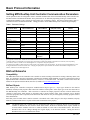
Introduction
This document contains the necessary information you need to incorporate a MicroTech II MPS Rooftop Unit Controller
from into your building automation system (BAS). It lists all BACnet® properties, LONWORKS® variables, and
corresponding MPS Rooftop Unit Controller data points. It also contains the BACnet Protocol Implementation
Conformance Statement (PICS). BACnet and LONWORKS terms are not defined in detail. Refer to the respective
specifications for more information.
MPS Rooftop Unit Controller Data Points
The MPS Rooftop Unit Controller contains data points or unit variables that are accessible from three user interfaces: the
unit keypad, a BACnet network (BACnet/IP, BACnet Ethernet or BACnet MS/TP), or a LONWORKS network. Not all points
are accessible from each interface. This manual lists all important data points and the corresponding path for each applicable
interface. Refer to the applicable Operation Manual for keypad details (see Reference Documents section). This document
contains the information necessary to incorporate the MPS Rooftop Unit Controller into a BACnet or LONWORKS network.
Protocol Definitions
The MPS Rooftop Unit Controller can be configured in either an interoperable BACnet or LONWORKS network. The
corresponding MicroTech II Communication Module must be installed on the MPS Rooftop Unit Controller. There are four
MicroTech II Communication Modules available:
BACnet/IP or BACnet Ethernet
BACnet MS/TP (Master/Slave Token Passing)
LONWORKS SCC (Space Comfort Control*)
LONWORKS DAC (Discharge Air Control*)
*The LONWORKS Communication Modules are in accordance with the LonMark® Space Comfort Controller functional
profile and the Discharge Air Controller functional profile.
BACnet Protocol
BACnet (Building Automation and Control Network) is a standard communication protocol developed by the American
National Standards Institute (ANSI) and American Society of Heating, Refrigeration and Air-conditioning Engineers
(ASHRAE) specified in ANSI/ASHRAE Standard 135-2001. BACnet provides the communication infrastructure needed to
integrate products manufactured by different vendors and to integrate building services that are now independent.
LONWORKS Networks
A control network specification for information exchange using LonTalk ® protocol for transmitting data developed by the
Echelon Corporation.
LonTalk Protocol
A protocol developed and owned by the Echelon Corporation. It describes how information should be transmitted between
devices on a control network.
LonMark Certification
LonMark certification is an official acknowledgement by the LonMark Interoperability Association that a product
communicates using the LonTalk protocol and transmits and receives data per a standard LonMark functional profile. The
MicroTech II MPS Rooftop Unit Controller is LonMark 3.4 certified.
ED 15102-4
5
Basic Protocol Information
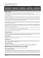
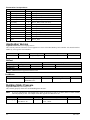
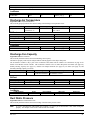
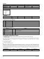
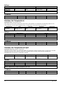
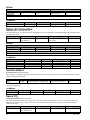
Setting MPS Rooftop Unit Controller Communication Parameters
Certain parameters must be configured in order to establish communication between the MPS Rooftop Unit Controller and
the MicroTech II Communication Module. These parameters are set differently depending on the type of MicroTech II
Communication Module. Table 1 defines the four possible sets of parameter settings. Note that not all parameters apply to
each MicroTech II Communication Module. Change parameters via the MPS Rooftop Unit Controller keypad display.
Table 1. Parameter Settings
IP Address
172.16.5.8
N/A
N/A
No Communication
Module
N/A
IP Subnet Mask1
16 (255.255.0.0)
N/A
N/A
N/A
47808
N/A
N/A
N/A
0.0.0.0
N/A
N/A
N/A
N/A
N/A
BACnet IP or BACnet
Ethernet
3001
N/A
N/A
1472
MTIIUC_MPSXXXXXXXXX
0
38400
BACnet MS/TP
N/A
N/A
LON
N/A
N/A
None
3001
127
1
480
MTIIUC_MPSXXX
XXXXXX
N/A
N/A
N/A
N/A
N/A
N/A
N/A
N/A
N/A
N/A
Parameter Name
UDP Port Number
2
IP Router Address
(Gateway)
MSTP MAC Address
MSTP Baud Rate
Type
Device Instance Number
Max Master
Max Info Frames
Max APDU Length
Device Object Name3
BACnet IP/Ethernet
BACnet MS/TP
LON (DAC or SCC)
Notes:
1
See Appendix B: Subnet Mask - CIDR Conversion Table for details on setting this parameter.
2
UDP Port Number is not adjustable via the unit keypad. The BACnet Communication Module Configuration Tool software (and corresponding
Users Manual, UM 855), available at www.DaikinApplied.com, is required to change this parameter.
3
The alpha portion (MTIIUC_MPS) of the Device Object Name is not adjustable via the keypad display. The numeric portion (XXXXXXXXX) is set to
the keypad editable Device Instance Number value. Changing the alpha portion requires the BACnet Communication Module Configuration Tool
software, available at www.DaikinApplied.com.
BACnet Networks
Compatibility
The MPS MicroTech II Unit Controller Unit Controller is tested according to the BACnet Testing Laboratory (BTL) Test
Plan. It is designed to meet the requirements of the BACnet Standard (ANSI/ASHRAE 135-2001) as stated in the Protocol
Implementation and Conformance Statement (PICS). However, it is not BTL listed. The PICS is located at the end of this
manual or the separate PICS document, ED 15107 (available on www.DaikinApplied.com.)
BACnet Objects
MPS Rooftop Unit Controllers incorporate standard BACnet object types (i.e., object types defined in the BACnet
Standard). Each object has properties that control unit variables or data points. Some object types occur more than once in
the MPS Rooftop Unit Controller. Each occurrence or instance has unique properties and also controls different unit
variables or data points. Each instance is designated with a unique instance index. Some properties can be adjusted
(read/write properties such as setpoints) from the network and others can only be interrogated (read-only properties such as
status information).
Each data point accessible from a BACnet network is described with a table that gives the Object Identifier, Property
Identifier, Full BACnet Reference or path, and the Name enumeration of the property.
Note:
6
The MPS Rooftop Unit Controller has been programmed with a Receive Heartbeat function for certain BACnet
variables. If BACnet has not written to these values before, the Receive Heartbeat timer expires (default=30
seconds) and the variables will revert to either the default or to the value of the attached sensor. The Receive
Heartbeat timer can be changed through the keypad display or the BACnet network. Setting the Receive
Heartbeat value to zero (0) disables this feature.
ED 15102-4
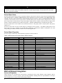
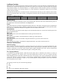
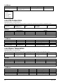
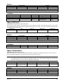
Example of BACnet Data Point
Keypad Menu Path Duct Pressure/1
Object Identifier
Object Type
Type ID
Analog Value
2
Property
Instance
1021
Name
Present Value
ID
85
Full Reference
MTIIUC_MPS#########.FanOutput.Present Value
Object Identifier
Object Identifiers are each designated with an Object type as defined in the BACnet specification. The first column of the
data point definition gives the object type. This object in the above example is Discharge Fan Capacity.
The object identifier is a property that can be read from the object. The name of the property is “Object_Identifier” and the
property identifier is 75.
Each object in a MPS Rooftop Unit Controller has a unique identifier. BACnet object identifiers are two-part numbers of
BACnet Object Identifier data type. The first part identifies the object type (the first 10 bits of the 32-bit BACnet Object
Identifier (see ANSI/ASHRAE 135-2001: BACnet A Data Communication Protocol for Building Automation and Control
Networks). The first column of the data point definition gives the object type. The second part identifies the instances of that
particular object type (the last 22 bits of the 32-bit BACnet Object Identifier).
The object identifier is shown in the data points listing as two numbers. The first number is shown in the Type ID column
and designates the Object type enumeration. The second number is shown in the Instance column and designates the
instance of that particular object type.
The object identifier is a property that can be read from the object code. The name of the property is “Object_Identifier” and
the property identifier is 75. The BACnet specification reserves the first 128 numbers for ASHRAE-defined objects.
Manufacturers may define additional object types and assign a number above 127 as long as they conform to the
requirements of the BACnet specification.
Each object also has a name. Object names are character strings. The object name is a property that can be read from the
object. The name of the property is “Object_Name” and the property identifier is 77.
Objects are sometimes referred to as an object type and instance number as they are in the BACnet specification. The
example object above is: Analog Value, Instance 1021.
Property Identifier
Each object has a number of properties or attributes. Each property has a unique identifier of BACnet Property Identifier
data type. Property identifiers are an enumerated set; a number identifies each member. The Property Identifier enumeration
number is shown in the Property ID column. In the example above the property identifier is 85.
Property Name
Each property also has a unique name. Property names are character strings and shown in the Property Name column. In the
example above the property name is Present Value.
Full Reference
The full reference is the path of the property within the network where the MPS Rooftop Unit Controller resides. It is a
character string equivalent to the object identifier and the property identifier. In the example above the full reference is
MTIIUC_MPS#########.FanOutput.Present Value.
Enumerated Values
Some properties are standard data types and some are enumerated sets. If the property value is an enumerated set, all
enumerated values and corresponding meaning are given in the Enumeration column of the data point listing.
MPS Rooftop Unit Controller Device Object
Each BACnet compatible device must contain only one BACnet Device Object.
Device Object Identifier
The MPS Rooftop Unit Controller Device Object Identifier uniquely specifies the unit within the network. The device object
type for all devices is fixed by ASHRAE at 8. Therefore the device object instance number must be unique. The initial
Device Object identifier is set at the factory. The device object identifier can be read from the MPS Rooftop Unit Controller.
The name of the property is “Object_Identifier” and the property identifier is 75. The initial device object instance number
is 3001.
ED 15102-4
7
!
CAUTION
If another device in the network already has this object identifier (instance number), you must change the instance
number of one device object via the MPS Rooftop Unit Controller keypad display, so that all devices in the network
have a unique device identifier.
Device Object Name
The device object name specifies a device and must be unique in the network. The device object name for the MPS Rooftop
Unit Controller device is MTIIUC_MPS#########, where ######### is the device instance of the MPS Rooftop Unit
Controller. The device object name must be unique throughout the entire network. If there are multiple MPS Rooftop Unit
Controllers on the network, the device object name of each MPS Rooftop Unit Controller must be changed to have a unique
device object name. To make the device object name unique, change the device instance, which must also be unique on the
network. All objects include the device name and a period “.” (MTIIUC_MPS#########.) preceding the object name.
The device object name is also available to the network in the device. The property name is “Object_Name” and property
identifier is 77.
The device object name can only be made unique by changing the device instance. The MTIIUC_MPS portion of the
device name can only be changed via the MicroTech II BACnet Communication Module Configuration Tool (and
corresponding User Manual, UM 855) available at www.DaikinApplied.com.
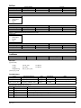
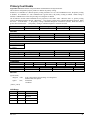
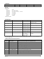
Device Object Properties
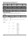
The device object contains many other informative properties as shown in Table 2.
Table 2. MPS Rooftop Unit Controller Device Object Properties
Property
Object Identifier
Object Name
Object Type
System Status
Vendor Name
Vendor Identifier
Model Name
Firmware Version
Application Software Revision
Location
Description
Protocol_Version
Protocol_Revision
Protocol_Services_Supported
Object_List
Max_APDU_Length_Accepted
Segmentation_Supported
Local_Time
Local_Date
UTC_Offset
Daylight_Savings_Status
APDU_Timeout
Identifier
75
77
79
112
121
120
70
44
12
58
28
98
139
97
76
62
107
57
56
119
24
11
Number_Of_APDU_Retries
Device_Address_Binding
Database_Revision
73
30
155
Value
8
Daikin
3
MPS Rooftop BCM
variable
variable
variable
1
4
Variable
No-Segmentation
variable
variable
variable
variable
variable
variable
55
Data Type
BACnetObjectIdentifier
CharacterString
BACnetObjectType
CharacterString
Unsigned16
CharacterString
CharacterString
CharacterString
CharacterString
CharacterString
Unsigned
Unsigned
BACnetServicesSupported
BACnetArray[N] of BACnetObjectIdentifier
Unsigned 16
Unsigned
Time
Date
Integer
Boolean
Unsigned
Unsigned
List of BACnetAddressBinding
Unsigned
BACnet Network Integration
Access to Properties
Object properties are accessible from the network by specifying the device object identifier, object identifier, and the
property identifier. To access a property, specify the object identifier including the device object identifier or the object
name including the device object name and the property identifier.
8
ED 15102-4
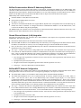
BACnet Communication Module IP Addressing Defaults
The BACnet/Internet Protocol (BACnet/IP) address of the BACnet Communication Module for the MPS Rooftop Unit
Controller in a BACnet/IP network consists of the four-octet Internet Protocol address followed by the two-octet UDP (User
Datagram Protocol) Port Number. The BACnet/IP address is a six-octet value analogous to a MAC (Media Access Control)
address. The IP address portion of the BACnet/IP address must be unique in the BACnet/IP network segment.
MPS Rooftop Unit Controller defaults are:
UDP Port Number: 47808 (BAC0 in hexadecimal)
Internet Protocol Subnet Mask: 255.255.0.0
IP Address: 172.16.5.8.
The BACnet Communication Module does support DHCP (Dynamic Host Configuration Protocol) IP addressing. By
default, this feature is disabled. To configure the BACnet Communication Module to use the DHCP feature, write
0.0.0.0 as the IP address using the keypad/display.
The MPS Rooftop Unit Controller can be incorporated into a BACnet/IP network dedicated to BACnet devices only or an
Ethernet network shared with BACnet devices and other devices.
Shared Ethernet Network (LAN) Integration
Integrating the MPS Rooftop Unit Controller into a shared Ethernet LAN requires close cooperation with the network
administrator. The steps are as follows:
Obtain the IP Subnet Mask of the shared network from the network administrator.
Obtain the static IP Addresses for all MPS Rooftop Unit Controllers you are integrating into the shared network. Obtain
the address of an IP Router or Gateway to use for sending IP messages to and from the BACnet IP subnets.
Once you have these, refer to Setting MPS Rooftop Unit Controller Communication Parameters in the Basic Protocol
Information section of this document.
The “Type=” variable on the Network Config hidden menu of the MPS Rooftop Unit Controller device object must be
set to BACnet IP or BACnet Ethernet for BACnet communications to take place. The default value for this property is
None. Refer to Setting MPS Rooftop Unit Controller Communication Parameters in the Basic Protocol Information
section of this document. To access the Network Config Menu of the keypad display, do the following:
1.
Press the upper left keypad button (with the left arrow icon) and lower left keypad button (with the down arrow
icon) simultaneously.
2.
If prompted for a password, enter: 4545.
3.
Navigate to the Network Config Menu (press the button with the right arrow icon once.)
4.
In the Type = field, select BACnet IP or BACnet Ethernet.
BACnet MS/TP Network Configuration
The BACnet MS/TP device address (MAC Address) of the MPS Rooftop Unit Controller in a BACnet Master Slave/Token
Passing (MS/TP) Local Area Network (LAN) is set using the keypad display. The steps are as follows:
The default MAC Address is 0. This address must be unique and is determined during installation.
The default data transmission rate is set to 38,400 bps (baud). If necessary, change the baud rate to 9600, 19200, or
76800. Note that this can be done via the MPS Rooftop Unit Controller keypad display or via the BACnet
Communication Module Configuration Tool software available at www.DaikinApplied.com. Please refer to Setting
MPS Rooftop Unit Controller Communication Parameters in the Basic Protocol Information section of this document.
The RS485 LEDs flicker green and red when the BACnet Communication Module is receiving data from the network.
If the red and green RS485 LEDs are on constantly together, then communication is not established.
The “Type=” variable on the Network Config hidden menu of the MPS Rooftop Unit Controller, the device object must
be set to BACnet MS/TP. Please refer to Setting MPS Rooftop Unit Controller Communication Parameters in the Basic
Protocol Information section of this document. To access the hidden Network Config Menu of the keypad display:
1.
Press the upper left keypad button (with the left arrow icon) and lower left keypad button (with the down arrow
icon) simultaneously.
2.
If prompted for a password, enter: 4545.
3.
Navigate to the Network Config Menu (press the button with the right arrow icon once.)
4.
In the Type = field, select BACnet MS/TP.
ED 15102-4
9
MPS Rooftop Unit Controller Configuration
The MPS Rooftop Unit Controller is ready to operate with the default values of the various parameters set at the factory.
Default values may be changed with the MPS Unit Controller keypad or via the network (see OM 843 for default values and
keypad operating instructions.)
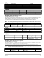
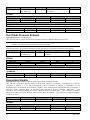
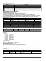
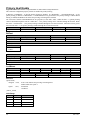
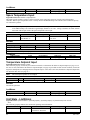
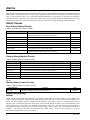
Data Integrity
The integrity of some data depends on a valid network connection to maintain current values. The following data points
require a valid network connection whether or not they are bound. If the data points shown in Table 3 do not change after a
given time, the Receive Heartbeat (ReceiveHrtBt) data points shown in of the MPS Rooftop Unit Controller reverts to the
default values of the variable or to the value of the attached sensor. Table 4 defines the effect on BACnet network variables
if the Receive Heartbeat timer should expire without having been updated.
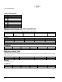
Table 3. Receive Heartbeat Variables - BACnet
Data Point
Occupancy Scheduler Input
Application Mode
Building Static Pressure
Remote Discharge Fan Capacity Setpoint
Remote Exhaust Fan Capacity Setpoint
Outdoor Air Temperature
Space Temperature
Space Indoor Air Quality (IAQ)
Primary Cool Enable
Primary Heat Enable
Primary Economizer Enable
BACnet Variable
OccState, NextOccState, TimeToNextOccState
ApplicCmd
BldgStaticPressInput
SupFanCapInput
ExhFanCapInput
OutdoorTempInput
SpaceTempInput
SpaceIAQInput
CoolEnable
HeatEnable
EconEnable
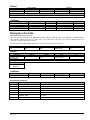
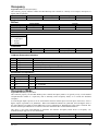
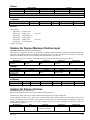
Table 4. Behavior of Network Variables upon Heartbeat Timer Expiration - BACnet
BACnet Network Variable
Action when Heartbeat Timer Expires Without Update
OccState, NextOccState, TimeToNextOccState
ApplicCmd
BldgStaticPressInput
SupFanCapInput
ExhFanCapInput
OutdoorTempInput
SpaceTempInput
SpaceIAQInput
CoolEnable
HeatEnable
EconEnable
nviPriCoolEnable.state
nviPriHeatEnable.state
nviPriEconEnable.state
Reverts to value of attached sensor
Reverts to value of attached sensor
Reverts to Normal Operation
Reverts to value of attached sensor
Stays at commanded value until power is cycled
Stays at commanded value until power is cycled
Reverts to value of attached sensor
(The next three sub-items are ncluded in nviOccSchedule menu
Reverts to Normal Operation
Reverts to Normal Operation
Reverts to Normal Operation
Reverts to Normal Operation
Reverts to Normal Operation
Reverts to Normal Operation
LONWORKS Networks
LONWORKS technology, developed by Echelon Corporation, is the basis for LonMark interoperable systems. This
technology is independent of the communications media. The LonMark Interoperable Association has developed standards
for interoperable LONWORKS technology systems. In particular, they have published standards for HVAC equipment
including the Discharge Air Controller (DAC) functional profile and the Space Comfort Controller (SCC) functional profile.
These profiles specify a number of mandatory and optional standard network variables and standard configuration
parameters. This document defines these variables and parameters available in the MPS Rooftop Unit Controller.
Compatibility
The MPS Rooftop Unit Controller with the LONWORKS Communication Module operates in accordance with DAC
functional profile or the SCC functional profile of the LonMark Interoperability standard.
10
ED 15102-4
LONWORKS Variables
MPS Rooftop Unit Controllers incorporate LONWORKS network variables to access unit data points. The MPS Rooftop Unit
Controller uses LONWORKS Standard Network Variable Types (SNVT) from each profile. Some data points can be adjusted
(input network variables, nvi) (read/write attributes, e.g., setpoints) from the network and others can only be interrogated
(output network variables, nvo) (read only attributes, e.g., status information). Configuration variables (nci) are included
with the read/write attributes.
Each data point accessible from a LONWORKS network is described with a table that gives the LONWORKS Name, Profile,
SNVT Type, and SNVT Index. If the variable is a configuration variable the table also includes the SCPT Reference and the
SCPT Index.
Example of LONWORKS Data Point
LONWORKS Name
Profile
nvoBldgStatPress
DAC, SCC
Uses Heartbeat
Yes
SNVT Type
SNVT Index
SNVT_press_p
113
LONWORKS Name
Each network variable has a name that you use to access the data point. This is the name of the variable from the profile. In
the example above, the network variable name is nvoBldgStatPress.
Profile
This column defines the LONWORKS-designated functional profile (SCC and/or DAC) incorporated by the Communication
Module for a given network variable. While the variable itself may not be a standard component of that particular profile,
the LONWORKS Communication Module does implement it and it is available to the network.
Uses Heartbeat
This column defines if the network variable output uses the Send Heartbeat function or if the network variable input uses the
Receive Heartbeat function.
SNVT Type
This column gives the name of the standard network variable type from the master list.
SNVT Index
This column gives the number of the standard network variable type from the master list.
SCPT Reference
This column gives the name of the Standard Configuration Parameter Type (SCPT) from the master list.
SCPT Index
This column gives the number of the Standard Configuration Parameter Type (SCPT) from the master list.
Network Considerations
Network Topology
Each LONWORKS Communication Module is equipped with an FTT-10A transceiver for network communications. This
transceiver allows for (1) free topology network wiring schemes using twisted pair (unshielded) cable and (2) polarity
insensitive connections at each node. These features greatly simplify installation and reduce network commissioning
problems. Additional nodes may be added with little regard to existing cable routing.
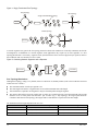
Free Topology Networks
A LONWORKS “free topology network“ means that devices (nodes) can be connected to the network in a variety of
geometric configurations. For example, devices can be daisy-chained from one device to the next, connected with stub
cables branching off from a main cable, connected using a tree or star topology, or any of these configurations can be mixed
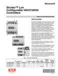
on the same network as shown in Figure 1. Free topology segments require termination for proper transmission
performance. Only one termination is required. It may be placed anywhere along the segment. Refer to the LONWORKS
FTT-10A Transceiver User’s Guide.
Free topology networks may take on the following topologies:
Bus
Ring
Star
Mixed - Any combination of Bus, Ring, and Star
Note: Limitations to wire lengths apply and must be observed.
ED 15102-4
11
Figure 1. Singly Terminated Free Topology
Ring Topology
Star Topology
Singly Terminated Bus Topology
Stub
Termination
Termination
}
Termination
Mixed Topology
Termination
A network segment is any part of the free topology network in which each conductor is electrically continuous. Each of the
four diagrams is an illustration of a network segment. Some applications may require two or more segments; see “Free
Topology Restrictions.” If necessary, segments can be joined with FTT-10A-to-FTT-10A physical layer repeaters. Refer to
the LONWORKS FTT-10A Transceiver User’s Guide.
Termination
FTT-10A
FTT-10A
Figure 2. Combining Network Segments with a Repeater
Termination
Free Topology Restrictions
Although free topology wiring is very flexible, there are restrictions. A summary follows (refer to the LONWORKS FTT-10A
Transceiver User’s Guide.)
The maximum number of nodes per segment is 64.
The total length of all cable in a segment must not exceed the maximum total cable length.
One termination is required in each segment. It may be located anywhere along the segment.
The longest cable path between any possible pair of nodes on a segment must not exceed the maximum node-to-node
distance. If two or more paths exist between a pair of nodes (e.g., a loop topology), the longest path should be
considered. Note that in a bus topology, the longest node-to-node distance is equal to the total cable length.
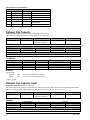
The maximum total bus length depends on the wire size:
Wire Size
Maximum Node-to-Node Length
Maximum Cable Length
24 AWG
820 ft (250 m)
1476 ft (450 m)
22 AWG
1312 ft (400 m)
1640 ft (500 m)
16 AWG
1640 ft (500 m)
1640 ft (500 m)
12
ED 15102-4
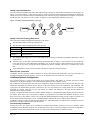
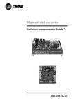
Doubly Terminated Networks
You can extend the maximum total cable length without using a repeater by using doubly-terminated network topology (see
Figure 3.) The trade-offs are (1) this network topology must be rigorously followed during the installation and subsequent
retrofits and (2) two terminations must be installed at the ends of the bus for proper transmission performance. Refer to the
LONWORKS FTT-10A Transceiver User’s Guide. Limitations to wire lengths apply and must be observed.
Figure 3. Doubly Terminated Network Topology
T
e
r
m
i
n
a
t
i
o
n
T
e
r
m
i
n
a
t
i
o
n
Doubly Terminated Topology Restrictions
The restrictions on doubly-terminated bus topology are as follows:
The maximum number of nodes per segment is 64.
The maximum total bus length depends on the wire size:
Wire Size
Maximum Cable Length
24 AWG
2952 ft (900 m)
22 AWG
4590 ft (1400 m)
16 AWG
8855 ft (2700 m)
The maximum stub length is 9.8 ft (3 m). The length of the LONWORKS Communication Module cable harness stub is
7.2 ft (2.19 m).
A stub is a piece of cable that is wired between the node and the bus (see Figure 1.) Note that if the bus is wired directly
to the node, there is no stub, and thus the stub length is zero. If you are wiring to a field terminal strip on a unit, be sure
to account for any factory wiring between the terminal strip and the controller. This wiring is considered part of the
stub.
Two terminations are required in each segment. One must be located at each end of the bus.
Network Cable Termination
LONWORKS network segments require termination for proper data transmission performance. The type and number of
terminations depend on network topology. . Refer to the LONWORKS FTT-10A Transceiver User’s Guide.
LONWORKS Network Configuration
Every Neuron Chip has a unique 48-bit Neuron ID or physical address. This address is generally used only at initial
installation or for diagnostic purposes. For normal network operation, a device address is used.
Device addresses are defined at the time of network configuration. All device addresses have three parts. The first part is the
Domain ID, designating the domain. Devices must be in the same domain in order to communicate with each other. The
second part is the Subnet ID that specifies a collection of up to 127 devices that are on a single channel or a set of channels
connected by repeaters. There may be up to 255 subnets in a domain. The third part is the Node ID that identifies an
individual device within the subnet.
A group is a logical collection of devices within a domain. Groups are assembled with regard for their physical location in
the domain. There may be up to 256 groups in domain. A group address is the address that identifies all devices of the
group. There may be any number of devices in a group when unacknowledged messaging is used. Groups are limited to 64
devices if acknowledged messaging is used. A broadcast address identifies all devices within a subnet or domain.
LONWORKS network variables for both the DAC and the SCC functional profiles are defined below. Variables are used in
both the SCC and DAC profiles unless marked otherwise.
Commissioning the Network
Pressing the service pin, switch on the LONWORKS Communications Module, generates a service pin message, which
contains the Neuron ID and the program code identification of the node. A service pin message is a network message that is
generated by a node and broadcast on the network. It can be used to commission the LONWORKS network.
ED 15102-4
13
A network configuration tool maps device Neuron IDs to the domain/subnet/node logical addressing scheme when it creates
the network image, the logical network addresses and connection information for all devices (nodes) on the network.
External Interface File (XIF)
LonMark guidelines specify exact documentation rules so that proprietary configuration tools are not required to
commission and configure LONWORKS devices. The LONWORKS Communication Module is self-documenting so that any
network management tool can obtain all the information needed over the network to connect it into the system and to
configure and manage it. An External Interface File (a specially formatted PC text file with an extension .XIF) is also
available so that any network tool can design and configure it prior to installation. XIF files are available on
www.DaikinApplied.com or www.lonmark.org.
Resource Files
Resource Files provide definitions of functional profiles, type definitions, enumerations, and formats that can be used by
network tools such as the LonMaker® tool. The MPS Rooftop Unit Controller supports the standard SCC and DAC
functional profiles. Additionally, certain Daikin-specific variables are defined for use with the MPS Rooftop Unit Controller.
The Resource Files define the format of how these Daikin-specific variables are displayed when using a tool such as
LonMaker. The DaikinDischargeAir (for use with LONWORKS DAC Communication Module) and DaikinRTU-SCC (for use
with LONWORKS SCC Communication Module) Resource Files are available on www.DaikinApplied.com or
www.lonmark.org.
MPS Rooftop Unit Controller Configuration
The MPS Rooftop Unit Controller with LONWORKS Communication Module is designed, programmed, and configured at
the factory to be in accordance with either the LonMark DAC or LonMark SCC functional profile. The unit is ready to
operate with the default values of the various parameters set at the factory. Default values may be changed with the MPS
Rooftop Unit Controller keypad display or via the network. See OM 843 for default values and keypad display operating
instructions (refer to Reference Documents section.)
The “Type=” property on the Network Config hidden menu of the keypad display must be set to LON for LONWORKS
network communication. . To access the hidden Network Config Menu of the keypad display:
1.
Press the upper left keypad button (with the left arrow icon) and lower left keypad button (with the down arrow
icon) simultaneously.
2.
If prompted for a password, enter: 4545.
3.
Navigate to the Network Config Menu (press the button with the right arrow icon once.)
4.
In the Type = field, select LON.
Refer to Setting MPS Rooftop Unit Controller Communication Parameters in the Basic Protocol Information section.
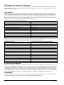
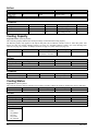
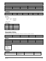
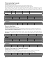
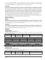
Data Integrity
The integrity of some data depends on a valid network connection to maintain current values. The data points shown in
Table 5 require a valid network connection whether or not they are bound. If data points listed in Table 5 do not change
after a given time (nciRcvHrtBt), the MPS Rooftop Unit Controller reverts to the default values of the variable or to the
value of the attached sensor. Table 6 defines the effect on LONWORKS network variables if the Receive Heartbeat timer
should expire without having been updated.
Table 5. Receive Heartbeat Variables - LONWORKS
Data Point
Occupancy Scheduler Input
Application Mode
Building Static Pressure
Remote Discharge Fan Capacity Setpoint
Remote Exhaust Fan Capacity Setpoint
Outdoor Air Temperature
Space Temperature
Space Indoor Air Quality (IAQ)
Primary Cool Enable
Primary Heat Enable
Primary Economizer Enable
14
LONWORKS Variable
nviOccSchedule
nviApplicMode
nviBldgStatPress
nviSupFanCap
nviExhFanCap
nviOutdoorTemp
nviSpaceTemp
nviSpaceIAQ
nviPriCoolEnable.state
nviPriHeatEnable.state
nviPriEconEnable.state
ED 15102-4
Table 6. Behavior of Network Variables upon Heartbeat Timer Expiration - LONWORKS
LONWORKS Network Variable
Action when Heartbeat Timer Expires Without Update
nviOutdoorTemp
nviSpaceTemp
nviApplicMode
nviBldgStatPress
nviSupFanCap
nviExhFanCap
nviSpaceIAQ
nviOccSchedule
.Current_State
.Next_State
.time_to_next_state
nviPriCoolEnable.state
nviPriHeatEnable.state
nviPriEconEnable.state
Reverts to value of attached sensor
Reverts to value of attached sensor
Reverts to Normal Operation
Reverts to value of attached sensor
Stays at commanded value until power is cycled
Stays at commanded value until power is cycled
Reverts to value of attached sensor
(The next three sub-items are ncluded in nviOccSchedule menu
Reverts to Normal Operation
Reverts to Normal Operation
Reverts to Normal Operation
Reverts to Normal Operation
Reverts to Normal Operation
Reverts to Normal Operation
ED 15102-4
15
Minimum Integration Requirements
This section provides general information and outlines the minimum requirements for system integration. Once the MPS
Rooftop Unit Controller has been configured, you can monitor and control unit operation from your workstation. At a
minimum, you can:
Display and monitor a minimum of important data points on your workstation display
Turn the unit on or off from your workstation
Set the schedule from your workstation and
Operate the unit safely
Set up the MPS Rooftop Unit Controller for Network Control
Follow the setup steps below to control the MPS Rooftop Unit Controller over the network:
1. On the unit keypad, set the Control Mode function to AUTO. The keypad password (4545) is required to edit this
function. For a detailed description of how to use the keypad, refer to the appropriate Operation Manual (See Reference
Documents section.) The keypad is also used to verify network operation.
2. Set “Type=” on the Network Config menu to the type of network that is connected (options shown on the keypad
display are: BACnet IP, BACnet Ethernet, BACnet MS/TP, and LON). To access the Network Config Menu of the
keypad display:
1.
Press the upper left keypad button (with the left arrow icon) and lower left keypad button (with the down arrow
icon) simultaneously.
2.
If prompted for a password, enter: 4545.
3.
Navigate to the Network Config Menu (press the button with the right arrow icon once.)
4.
In the Type = field, select BACnet IP, BACnet Ethernet, BACnet MS/TP, or LON.
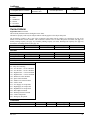
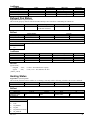
Display Important Data Points
A typical workstation displays MPS Rooftop Unit Controller includes the following significant data points as shown in
Table 7 (page number of detailed description in parenthesis). Each data point includes a number that also identifies it in the
Comprehensive Data Point Tables. These data points are also shaded in the Comprehensive Data Point Tables so that you
can distinguish them from the rest of the data points in the table. References in the text of this section also identify these
data points with a number and shading.
Table 7. Significant Data Points
No
Configuration
No
Temperatures/Pressures
No
1
2
3
4
Unit Status (52)
Application Mode (23)
Occupancy (39)
Occupancy Mode (39)
5
6
7
8
Discharge Air Temp (28)
Return Air Temp (48)
Outdoor Air Temp (44)
Duct Static Pressure (29)
9
10
11
12
13
Setpoints
No
Clear Alarms
Duct Static Pressure Setpoint (30) 14 Clear All Alarms (55)
Unoc Cooling Setpoint (52)
15 Clear One Alarm (55)
Occ Cooling Setpoint (42)
Occ Heating Setpoint (42)
Unoc Heating Setpoint (53)
You can display any number of additional data points based on job requirements or individual preference. See LonWorks
Variables on page 20 for a comphrensive list of all LONWORKS Variables available in a LONWORKS network. See BACnet
Standard Objects on page 18 for a comphrensive list of all Standard BACnet Objects available in a BACnet network. For a
more detailed description of all available data points, see the Detailed Data Point Information section on page 23.
Network Off
The unit can be turned off over the network by writing to the (2) Application Mode (See page 23). Writing AUTO to
Application Mode allows the MPS Rooftop Unit Controller to determine its mode of operation based on input conditions.
Writing OFF to Application Mode shuts down the unit, etc.
The Emergency Override variable (See page 33) can also be used to shut down the unit from the network.
Network Occupancy Scheduling
Using the unit keypad display, set the Occupancy Mode to Auto. Schedule unit operation over the network with the Occ
Scheduler input. Switching from OCC, UNOCC, BYPASS, or AUTO commands the unit into the mode you select.
16
ED 15102-4
Alarms
Alarms in a MPS Rooftop Unit Controller are divided into three classes: Faults, Problems, and Warnings.
Fault Alarms have the highest priority
Problem Alarms have medium priority
Warning Alarms have the lowest priority
Monitoring Alarms
BACnet
Alarms within a MPS Rooftop Unit Controller can be monitored individually by using the Alarm (AV1019) attribute. This
attribute displays a value that corresponds to the highest priority alarm that is active. It is possible to have multiple active
alarms, but only the highest priority is displayed in this attribute. For example, if there is a simultaneous Dirty Filter
Warning (value of 24) and an Emergency Fault (value of 250), then the Emergency Fault value of 250 will display in the
Present_Value of AV 1019 because it is the higher priority alarm of the two. Once the Emergency Fault condition is
corrected and the fault is cleared, the next priority active alarm value (in this example, value of 24 for Dirty Filter alarm) is
displayed. The values for all alarms are described in the Alarms section. If the AV 1019 displays a zero in the
Present_Value property, there are no active alarms.
Alarm Class may also monitor alarms, if desired. When the Present_Value of AV1019 attribute reads a value in the range
of 1 to 99, a Warning Alarm is active. When the attribute reads a value in the range of 100 to 199, a Problem Alarm is
active. When the attribute reads a value in the range of 200 to 255, a Fault Alarm is active.
LONWORKS
Alarms within a MPS Rooftop Unit Controller can be monitored individually by using the In Alarm attribute. The In Alarm
attribute is part of the Unit Status Network Variable Output (i.e. nvoUnitStatus.in_alarm). This attribute displays a value
that corresponds to the highest priority alarm that is active. It is possible to have multiple active alarms, but only the highest
priority is displayed in this attribute. For example, if there is a simultaneous Dirty Filter Warning (value of 24) and an
Emergency Fault (value of 250), then the Emergency Fault value of 250 will display in nvoUnitStatus.in_alarm because it is
the higher priority alarm of the two. Once the Emergency Fault condition is corrected and the fault is cleared, the next
priority active alarm value (in this example, value of 24 for Dirty Filter alarm) is displayed. The values for all alarms are
described in the Alarms section. If the attribute nvoUnitStatus.in_alarm displays a zero, there are no active alarms.
Alarm Class may also monitor alarms, if desired. When the nvoUnitStatus.in_alarm attribute reads a value in the range of 1
to 99, a Warning Alarm is active. When the attribute reads a value in the range of 100 to 199, a Problem Alarm is active.
When the attribute reads a value in the range of 200 to 255, a Fault Alarm is active.
Clearing Alarms
BACnet
Alarms can be cleared via BACnet by alarm class using two BACnet variables. To clear all active alarms, change the
Present_Value property of Binary Value 4 (Clear All Alarms) to a 1. To clear one of the active alarms, change the
Present_Value property of Analog Value 1029 (Clear One Alarm) to the value of the alarm you want to clear. For example,
if you want to clear an Emergency Fault alarm, write 250 to Analog Value 1029.
LONWORKS
Alarms can be cleared using two Network Variable Inputs (nviClear1Alarm or nviClearAllAlarm) of type SNVT_count. To
clear all active alarms, change nviClearAllAlarm to 1. To clear one active alarm, change nviClear1Alarm to the value of the
alarm you want to clear. For example, if you want to clear an Emergency Fault alarm, write 250 to nviClear1Alarm.
MPS Rooftop Unit Controller Sequence of Operation
The sequence of operation for a MPS Rooftop Unit Controller depends on the control type. Refer to OM 843 for sequence
of operation and keypad display details (see Reference Documents section).
ED 15102-4
17
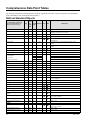
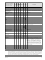
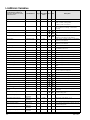
Comprehensive Data Point Tables
The following comprehensive data point tables contain the significant parameters of specific data points. The shaded data
points with numbers refer to data points listed in Table 7.
BACnet Standard Objects
Network Control Property
(Keypad attributes available as
BACnet Standard Objects for
network control of the unit)
Read
Or
Object
Page
Instance SCC DAC
Read/ Type
Write
System
Unit Status
52
R
MV
1025
Cooling Capacity
26
R
AV
1016
Primary Heating Capacity
47
R
AV
1015
Cooling Status
26
R
MV
1023
Heating Status
35
R
MV
1024
Economizer Status
31
R
MV
1022
Outdoor Air Damper Position
43
R
AV
1017
Occupancy
Occupancy
39
R
MV
1014
40
R/W
MV
MV
AV
1011
1012
1013
10
14
15
13
Occupancy Scheduler Input
Current State
Next State
Time To Next State
Temperatures
Discharge Air Temperature
29
R
AV
Return Air Temperature
48
R
AV
Space Temperature
49
R
AV
Outdoor Air Temperature
44
R
AV
Local Space Temperature
36
Local OA Temperature
36
Duct Pressure
Duct Static Pressure
29
R
AV
Discharge Fan Capacity
29
R
Building Pressure
Building Static Pressure
24
Building Static Pressure Setpoint
25
Exhaust Fan Capacity
34
Description
1=Off, 2=Startup, 3=Recirc, 4=Fan Only, 5=MinDAT,
6=Heating, 7=Economizer, 8=Cooling
Feedback of cooling capacity (%)
Feedback of heating capacity (%)
1=Enabled, 2=None, 3=Off Manual, 4=Off Net, 5=Off Alarm,
6=Off Ambient
1=Enabled, 2=None, 3=Off Manual, 4=Off Net, 6=Off
Ambient
1=Enabled, 2=None, 3=Off Manual, 4=Off Net, 6=Off
Ambient
Feedback value (%)
1=Occupied, 2=Unoccupied, 3=Bypass, 4=Standby**
1=Occupied, 2=Unoccupied, 4=Standby, 5=Auto**
1=Occupied, 2=Unoccupied, 4=Standby, 5=Auto**
Default = 0 seconds
Current reading of Discharge Air Temp sensor
1021
N/A
AV
1018
Current reading of sensor. If unit has two sensors the lower of
the two is displayed
Current discharge fan capacity (%)
R
AV
1020
AV
1006
R
AV
1030
Current reading of sensor value or network input
R/W
38
R/W
AV
2
N/A
Default = 55°F
32
R
AV
12
Occupied Cooling Setpoint
42
R/W
AV
6
Unoccupied Cooling Setpoint
52
R/W
AV
7
If Control Temp > (this setpoint + ½ Cool Enable Dead Band),
Then cooling is enabled
Default = 72°F
Heating
Effective Setpoint Output
32
R
AV
12
Occupied Heating Setpoint
42
R/W
AV
8
Unoccupied Heating Setpoint
53
R/W
AV
9
Zone Cooling
Minimum Discharge Air Cooling
Setpoint
Effective Setpoint Output
18
Current reading of sensor
Current reading of sensor
Current reading of sensor
Current reading of the local space sensor
Current reading of the local outdoor air temperature sensor
Default = 0.050” WC
Current exhaust fan capacity (%)
Default = 85°F
If Control Temp < (this setpoint – ½ Heat Enable Dead Band),
Then heating is enabled
Default = 68°F
Default = 55°F
ED 15102-4
Network Control Property
(Keypad attributes available as
BACnet Standard Objects for
network control of the unit)
Page
Read
Object
Or
Instance SCC DAC
Read/ Type
Write
Default = 113°F/45°C
Current discharge air cooling setpoint the unit controller is
using.
1009
Default = 10%
Max Discharge Air Heating Setpoint
37
R/W
AV
19
Discharge Air Heating Setpoint
28
R/W
AV
18
32
R
AV
11
43
R/W
AV
Discharge Cooling
Effective Discharge Air
Temperature Setpoint
Min OA Damper
Outdoor Air Damper Minimum
Position Input
Space CO2
Description
48
R
AV
1031
Economizer Enable
30
R/W
AV
BV
1028
3
Unit Configuration
Application Version
24
R
AV
1032
Remote Discharge Fan Capacity
Setpoint
Network Config
Application Mode
47
R/W
AV
1007
N/A
23
R/W
MV
1002
Occupancy Mode
39
R/W
MV
1001
Emergency Override
33
R/W
AV
1003
Duct Static Pressure Setpoint
30
R/W
AV
1004
N/A
Space Temperature Input
50
R/W
AV
4
Outdoor Air Temperature Input
44
R/W
AV
3
Discharge Air Cooling Setpoint
28
R/W
AV
1
N/A
Building Static Pressure Input
25
R/W
AV
1005
Exhaust Fan Capacity Input
34
R/W
AV
1008
Primary Heat Enable
46
R/W
Primary Cool Enable
45
R/W
49
R/W
2
1027
1
1026
1010
Space IAQ Input
BV
AV
BV
AV
AV
Receive Heartbeat
47
R/W
AV
5
Active Alarms
Current Alarm
27
R
AV
1019
Clear All Alarms
55
R/W
BV
4
Clear One Alarm
55
R/W
AV
1029
Non-Keypad Variables
Exhaust Fan Status
35
R
BV
5
Default = 0%
1=Off, 2=HeatOnly, 3=CoolOnly, 4=FanOnly, 5=Auto,
1=Occupied, 2=Unoccupied, 3=Bypass, 4=Standby, 5=Auto
0=Normal, 4=Shutdown (Shuts unit off via a network signal,
puts Unit Status = OffNet)
Default = 1.00” WC
Default = 32767
Default = 32767
0 = No Active Alarm, 24 = Dirty Filter Warning, 158 = Low
Pressure – Circuit 2 Problem, 159 = Low Pressure – Circuit 1
Problem, 166 = High Pressure – Circuit 2 Problem, 167 =
High Pressure – Circuit 1 Problem, 182 = Return Air Sensor
Problem, 185 = Space Sensor Problem, 188= Outdoor Air
Sensor Problem, 208 = Airflow Fault, 212 = Low Supply Air
Temp Fault, 216 = High Supply Air Temp Fault, 220 = High
Return Air Temp Fault, 224 = Duct High Limit Fault, 228 =
Discharge Sensor Fail Fault, 244 = Control Temp Fault, 250 =
Emergency Stop Fault
Clears all active alarms.
Clears the alarm that corresponds to the value entered.
** If Standby is selected, the unit will operate in Occupied mode.
Note:
For variables that use the Receive Heartbeat feature (see Table 3), the MPS Rooftop Unit Controller assumes
network communication is lost and will revert to the last written value or the value of the local sensor if the
network has not written a value within the Receive Heartbeat time (default=30 seconds). The Receive Heartbeat
time can be changed using the keypad display or through the BACnet network. Setting Receive Heartbeat to 0
causes the value to remain at the network default if communications is lost, which is not recommended.
ED 15102-4
19
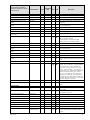
LONWORKS Variables
Network Control Property
Keypad attributes available as
LONWORKS Variables for network
control of the unit
Variable Name
Page
SNVT/SCPT
SCC DAC
Index
Description
System
Unit State - LON
nvoUnitStatus
50
112
Daikin RTU Unit State
nvoMcQRTUStatus
52
N/A
Cooling Capacity
nvoUnitStatus
26
112
Primary Heating Capacity
nvoUnitStatus
47
112
Cooling Status
nvoMcQRTUStatus
26
N/A
Heating Status
nvoMcQRTUStatus
35
N/A
Economizer Status
nvoMcQRTUStatus
31
N/A
Occupancy
Occupancy
nvoEffectOccup
39
109
Occupancy Scheduler Input
nviOccSchedule
40
128
Temperatures
Discharge Air Temperature
nvoDischAirTemp
28
105
nvoRATemp
48
105
Space Temperature
nvoSpaceTemp
49
105
Outdoor Air Temperature
nvoOutdoorTemp
44
105
Local Space Temperature
nvoLocalSpaceTmp
36
105
Local OA Temperature
nvoLocalOATemp
36
105
Current reading of Discharge Air Temp sensor
Return Air Temperature
Duct Pressure
Duct Static Pressure
nvoDuctStatPress
29
113
Duct Static Pressure Setpoint
nviDuctStaticSP
30
113
Discharge Fan Capacity
nvoUnitStatus
29
112
Current reading of sensor. If unit has two sensors
the lower of the two is displayed
Default = 1.00” WC
Bld Pressure Control
Exhaust Fan Capacity
nvoExhFanStatus
34
95
nviBldgStatPress
25
113
Building Static Pressure
nvoBldgStatPress
24
113
Building Static Pressure Setpoint
nviBldgStaticSP
25
113
Current exhaust fan capacity (%)
Building Static Pressure Input
nciDAClSP
38
105
nvoEffectSetpt
32
105
nciSetpoints
SCPTsetPnts
nciSetpoints
SCPTsetPnts
42
106/60
Used to set the discharge air cooling setpoint via
the network.
Current cooling enable setpoint which the unit will
use in the cooling mode
Occupied_Cool Default = 72°F
52
106/60
Unnoccupied_Cool Default = 85°F
nvoEffectSetpt
32
105
nciSetpoints
SCPTsetPnts
nciSetpoints
SCPTsetPnts
42
106/60
Current heating enable setpoint which the unit will
use in the heating mode
Occupied_Heat Default = 68°F
53
106/60
Unoccupied_Heat Default = 55°F
Zone Cooling
Minimum Discharge Air Cooling
Setpoint
Effective Setpoint Output
Occupied Cooling Setpoint
Unoccupied Cooling Setpoint
Heating
Effective Setpoint Output
Occupied Heating Setpoint
Unoccupied Heating Setpoint
20
Mode 1=HEAT, 2=MRNG_WRMUP, 3=COOL,
6=OFF, 7=TEST, 9=FAN_ONLY,
10=FREE_COOL (Economizer)
Unit_Mode 1=Off, 2=Startup, 3=Recirc, 4=Fan
Only, 5=MinDAT, 6=Heating, 7=Economizer,
8=Cooling
Cool_Output Feedback of cooling capacity (%)
Heat_Output Feedback of primary heating capacity
(%)
Cooling Status 1=Enabled, 2=None, 3=Off Manual,
4=Off Net, 5=Off Alarm, 6=Off Ambient
Heating Status 1=Enabled, 2=None, 3=Off Manual,
4=Off Net, 6=Off Ambient
Econo Status 1=Enabled, 2=None, 3=Off Manual,
4=Off Net, 6=Off Ambient
0=OCCUPIED, 1=UNOCCUPIED, 2=BYPASS,
3=STANDBY, 0xFF=NUL
Network schedule
Current reading of sensor
Current reading of sensor
Current reading of sensor
Current reading of the local space sensor
Current reading of the local outdoor air temperature
sensor
Fan_Output Current discharge fan capacity (%)
Network input of Building Static Pressure
Current reading of sensor value
Default = 0.050” WC
ED 15102-4
Network Control Property
Keypad attributes available as
LONWORKS Variables for network
control of the unit
Variable Name
Page
SNVT/SCPT
SCC DAC
Index
Description
Max Discharge Air Heating Setpoint
nciDAHtSP
37
1050/184
nviDAHtSP
28
105
Default = 113°F/45°C
Discharge Air Heating Setpoint
38
183
32
105
28
105
Used to set the discharge air cooling setpoint via
the network.
Current discharge air setpoint which the unit will
use in the cooling mode
Default = 55°F
nvoUnitStatus
43
112
Outdoor Air Damper Minimum
Position Input
Economizer Enable
nviOAMinPos
43
nviEconEnable
Space CO2
nvoSpaceCO2
Discharge Cooling
Minimum Discharge Air Cooling
nciDAClSP
Setpoint
Effective Discharge Air Temperature nvoEffDATempSp
Setpoint
Discharge Air Cooling Setpoint
nviDAClSP
Min OA Damper
Outdoor Air Damper Position
Economizer_Output Feedback value (%)
81
30
95
48
29
Enables or disables economizer via two properties:
State=0, economizer disabled
Value=0 and State=1, economizer disabled
Value>0 and State=1, economizer enabled
0-5000ppm
32
105
37
105/184
24
8
nviSupFanCap
47
81
Alarms
Current Alarm
nvoUnitStatus
27
112
Clear All Alarms
nviClearAllAlarm
55
8
Clear One Alarm
nviClear1Alarm
55
8
Network Config
Application Mode
nviApplicMode
23
108
Occupancy Mode
nviOccManCmd
39
109
Exhaust Fan Capacity Input
nviExhFanCap
34
81
Primary Heat Enable
nviPriHeatEnable
46
95
Primary Cool Enable
nviPriCoolEnable
45
95
Space IAQ Input
nviSpaceIAQ
49
29
Emergency Override
nviEmergOverride
33
103
Space Temperature Input
nviSpaceTemp
50
105
Outdoor Air Temperature Input
nviOutdoorTemp
44
105
Minimum Send Time
nciMinOutTm
SCPTminSendTime
38
107/52
Discharge Heating
Effective Discharge Air Temperature nvoEffDATempSp
Setpoint
Maximum Discharge Air Heating
nciDAHtSP
Setpoint
Unit Configuration
Application Version
nvoAppVersion
Remote Discharge Fan Capacity
Setpoint
ED 15102-4
Current OA damper min position setpoint (%)
Current discharge air setpoint which the unit will
use in the heating mode
Default=0%. Sets the discharge air VFD speed
when Discharge Fan Capacity Control Flag is set to
Speed.
In_Alarm 0 = No Active Alarm, 24 = Dirty Filter
Warning, 158 = Low Pressure – Circuit 2 Problem,
159 = Low Pressure – Circuit 1 Problem, 166 =
High Pressure – Circuit 2 Problem, 167 = High
Pressure – Circuit 1 Problem, , 182 = Return Air
Sensor Problem, 185 = Space Sensor Problem, 188
= Outdoor Air Sensor Problem, 208 = Airflow
Fault, 212 = Low Supply Air Temp Fault, 216 =
High Supply Air Temp Fault, 220 = High Return
Air Temp Fault, 224 = Duct High Limit Fault, 228
= Discharge Sensor Fail Fault, 244 = Control Temp
Fault, 250 = Emergency Stop Fault
Clears all alarms.
Clears the alarm that corresponds to the value
entered.
0=AUTO, 1=HEAT, 3=COOL, 6=OFF,
9=FAN_ONLY
0=OCCUPIED, 1=UNOCCUPIED, 2= BYPASS,
3=STANDBY, 0xFF=NUL
0-5000ppm
0=NORMAL, 4=SHUTDOWN
Network input of Space Temperature
Network input of Outdoor Air Temperature
Defines min period of time between automatic
network variable output time (reducing traffic on
network)
21
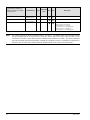
Network Control Property
Keypad attributes available as
LONWORKS Variables for network
control of the unit
Receive Heartbeat
Send Heartbeat
Temperature Setpoint Input
Note:
22
Variable Name
nciRcvHrtBt
SCPTmaxRcvTime
nciSndHrtBt
SCPTmaxSendTime
nviSetpoint
Page
SNVT/SCPT
SCC DAC
Index
Description
47
107/48
Default is 30 seconds
48
107/49
Default is 60 seconds
50
105
Adjusts effective heat enable and effective cool
enable setpoint via the network.
Effective Heat SP = nviSetpoint –
0.5 (Occupied_Cool – Occupied_Heat).
Effective Cool SP = nviSetpoint +
0.5 (Occupied_Cool – Occupied_Heat).
For variables that use the Receive Heartbeat feature, see Table 5. The MPS Rooftop Unit Controller assumes
network communication is lost and will revert to the last written value or the value of the local sensor if the
network has not written a value within the Receive Heartbeat time (default=30 seconds). The Receive Heartbeat
time can be changed using the keypad display or through the LONWORKS network. Setting Receive Heartbeat to 0
causes the value to remain at the network default if communications is lost, which is not recommended.
ED 15102-4
Detailed Data Point Information
The following section defines the data points or properties (attributes) generated by the MPS Rooftop Unit Controller.
Application Mode
Keypad Menu Path System/Appl Mode=
This read/write attribute sets the unit in an application mode (auto, off, heat only, cool only, or fan only). Application Mode
does not "force" the unit into any state. However, it disables certain unit operation. An Application Mode of "Cool Only"
disables Heating, "Heat Only" disables Cooling, and "Fan Only" disables Heating and Cooling. This attribute has no affect
unless Control Mode is set to Auto. Control Mode is only set at the keypad/display.
Measurement
Mode
Units
Data Type
NA
Valid Range
Real
Default Value
Enumerated
NA
BACnet
Object Type
Multistate Value
Object Identifier
Type ID
19
Property
Instance
Name
1002
ID
Present Value
85
Full Reference
MTIIUC_MPS#########.ApplicCmd.Present Value
Enumeration
1 = Off
2 = Heat Only
3 = Cool Only
4 = Fan Only
5 = Auto (Heat/Cool)
LONWORKS
LONWORKS Name
nviApplicMode
Profile
DAC, SCC
Uses Heartbeat
Yes
SNVT Type
SNVT_hvac_mode
SNVT Index
108
LONWORKS Enumeration Definitions
Value
Identifier
0
1
2
3
4
5
6
7
8
9
10
11
12
13
14
15
16
17
0xFF
HVAC_AUTO
HVAC_HEAT
HVAC_MRNG_WRMUP
HVAC_COOL
HVAC_NIGHT_PURGE
HVAC_PRE_COOL
HVAC_OFF
HVAC_TEST
HVAC_EMERG_HEAT
HVAC_FAN_ONLY
HVAC_FREE_COOL
HVAC_ICE
HVAC_MAX_HEAT
HVAC_ECONOMY
HVAC_DEHUMID
HVAC_CALIBRATE
HVAC_EMERG_COOL
HVAC_EMERG_STEAM
HVAC_NUL
ED 15102-4
Notes
Controller automatically changes between application modes
Heating only
Not supported – reverts to HVAC_AUTO
Cooling only
Not supported – reverts to HVAC_AUTO
Not supported – reverts to HVAC_AUTO
Controller not controlling outputs
Not supported – reverts to HVAC_AUTO
Not supported – reverts to HVAC_AUTO
Air not conditioned, fan turned on
Not supported – reverts to HVAC_AUTO
Not supported – reverts to HVAC_AUTO
Not supported – reverts to HVAC_AUTO
Not supported – reverts to HVAC_AUTO
Not supported – reverts to HVAC_AUTO
Not supported – reverts to HVAC_AUTO
Not supported – reverts to HVAC_AUTO
Not supported – reverts to HVAC_AUTO
Value not available
23
Enumeration Correspondence
BACnet
5
2
2
3
3
3
1
5
2
4
3
5
5
5
LONWORKS
Auto
Heat Only
Heat Only
Cool Only
Cool Only
Cool Only
Off
Auto
Heat Only
Fan Only
Cool
Auto
Auto
Auto
0
1
2
3
4
5
6
7
8
9
10
11
12
0xFF
HVAC_AUTO
HVAC_HEAT
HVAC_MRNG_WRMUP (not used)
HVAC_COOL
HVAC_NIGHT_PURGE (not used)
HVAC_PRE_COOL (not used)
HVAC_OFF
HVAC_TEST (not used)
HVAC_EMERG_HEAT (not used)
HVAC_FAN_ONLY
HVAC_FREE_COOL (not used)
HVAC_ICE (not used)
HVAC_MAX HEAT (not used)
HVAC_NUL
Application Version
Keypad Menu Path Hidden.Unit Config/App Version=
This read only attribute reflects the current Application Version of the MPS Rooftop Unit Controller. You must divide this
number by 100 to get the version number.
Measurement
Event Count
Units
Data Type
NA
Valid Range
Unsigned long
0-65,535
Instance
Name
Default Value
NA
BACnet
Object Identifier
Type ID
Object Type
Analog Value
2
Property
1032
ID
Present Value
85
Full Reference
MTIIUC_MPS#########.AppVersion.Present Value
LONWORKS
LonWorks Name
nvoAppVersion
Profile
Uses Heartbeat
DaikinDischargeAir,
DaikinRTU-SCC
No
UNVT Type
SNVT Number
UNVTAppVersion
N/A
Building Static Pressure
Keypad Menu Path Bldg Pressure/Bldg Press=
This read only property reflects the current Building Static Pressure.
Note:
If you are using BACnet with English units, divide the property by 1000 to get IWC (inches of water column)
when the property is read. For example, 0.050 IWC appears over BACnet as 50.
Measurement
Pressure (gauge)
24
Units
BACnet: IWC / Pa
LONWORKS: Pa
Data Type
Real
Valid Range
-0.250 – +0.250 IWC
-100 .. 100 Pa
Default Value
NA
ED 15102-4
BACnet
Object Identifier
Type ID
Object Type
Analog Value
2
Property
Instance
Name
1020
ID
Present Value
85
Full Reference
MTIIUC_MPS#########.EffectBldgStaticP.Present Value
LONWORKS
LONWORKS Name
Profile
nvoBldgStatPress
Uses Heartbeat
DAC
LonWorks Name
Yes
Profile
SNVT_press_p
Uses Heartbeat
DaikinRTU-SCC
nvoBldgStatPress
SNVT Type
SNVT Index
113
UNVT Type
Yes
SNVT Number
UNVTBldgStatPressOut
N/A
Building Static Pressure Input
Keypad Menu Path Hidden.Network Config/nviBSP
This read/write property connects a network building static pressure sensor or network output from another device. When a
building static pressure sensor is locally wired to the controller, this variable has priority if a valid value is present.
If the Present Value is set beyond the valid range from the network, the value from the network is ignored.
Note:
Using BACnet with English units requires that you divide the variable by 1000 to get IWC when the property is
read. For example, 0.050 IWC appears over BACnet as 50.
Measurement
Pressure (gauge)
Units
Data Type
BACnet: IWC / Pa
LONWORKS: Pa
Real
Valid Range
Default Value
-0.50 – +0.50 WC
-125 .. 125 Pa
NA
BACnet
Object Identifier
Type ID
Object Type
Analog Value
2
Property
Instance
Name
1005
Present Value
ID
85
Full Reference
MTIIUC_MPS#########.BldgStaticPressInput.Present Value
LONWORKS
LONWORKS Name
Profile
nviBldgStatPress
Uses Heartbeat
DAC
LonWorks Name
Yes
Profile
SNVT_press_p
Uses Heartbeat
DaikinRTU-SCC
nviBldgStatPress
SNVT Type
Yes
UNVT Type
UNVTBldgStatPress
SNVT Index
113
SNVT Number
N/A
Building Static Pressure Setpoint
Keypad Menu Path Bldg Pressure/BldgSP Spt=
This read/write property sets the Building Static Pressure Setpoint used for controlling the exhaust fan VFD. The VFD is
modulated to maintain the building static pressure sensor input at this Setpoint.
If the Present Value is set beyond the valid range from the network, the value written from the network is ignored.
Note:
If you are using BACnet with English units, divide the variable by 1000 to get IWC when the property is read.
For example, 0.050 IWC appears over BACnet as 50.
Measurement
Pressure (gauge)
ED 15102-4
Units
BACnet: IWC / Pa
LONWORKS: Pa
Data Type
Real
Valid Range
-0.250 – +0.250 IWC
-100 ..100 Pa
Default Value
NA
25
BACnet
Object Identifier
Type ID
Object Type
Analog Value
2
Property
Instance
1006
Name
ID
Present Value
85
Full Reference
MTIIUC_MPS#########.BldgStaticSPInput.Present Value
LONWORKS
LONWORKS Name
Profile
nviBldgStaticSP
Uses Heartbeat
DAC
LonWorks Name
No
Profile
Uses Heartbeat
DaikinRTU-SCC
nviBldgStaticSP
SNVT Type
No
SNVT Index
SNVT_press_p
113
UNVT Type
SNVT Number
UNVTBldgStaticSP
N/A
Cooling Capacity
Keypad Menu Path System/Clg Capacity
This read-only property indicates the current percentage of unit maximum cooling capacity.
The BACnet property only applies to the subject data point. The LONWORKS variable covers six other data points: Unit
Status (see page 50), Primary Heating Capacity (see page 47), Secondary Heating Capacity (not used), Discharge Fan
Capacity (see page 29), Outdoor Air Damper Position (see page 43), and In Alarm (see page 27).
Measurement
Percent
Units
NA
Data Type
BACnet: Real
LONWORKS: Structure
Valid Range
0-100%
Default Value
NA
BACnet
Object Identifier
Type ID
Object Type
Analog Value
2
Property
Instance
1016
Name
Present Value
ID
85
Full Reference
MTIIUC_MPS#########.CoolOutput.Present Value
LONWORKS
LONWORKS Name
Profile
nvoUnitStatus.cool_output
DAC, SCC
Uses Heartbeat
Yes
SNVT Type
SNVT_hvac_status
SNVT Index
112
Cooling Status
Keypad Menu System/Clg Status=
This read-only attribute indicates whether or not cooling is currently enabled. If cooling is disabled, the reason is indicated.
Measurement
State
Units
NA
Data Type
Real
Valid Range
Enumerated
Default Value
NA
BACnet
Object Identifier
Type ID
Object Type
Multistate Value
19
Property
Instance
1023
Name
Present Value
ID
85
Full Reference
MTIIUC_MPS#########.CoolStatus.Present Value
Enumeration
1=
2=
3=
4=
5=
6=
26
Enabled
None
Off_Manual
Off_Net
Off_Alarm
Off_Ambient
ED 15102-4
LONWORKS
LonWorks Name
Profile
nvoMcQRTUStatus.CoolStatus
DaikinDischargeAir,
DaikinRTU-SCC
UNVT Type
SNVT Number
UNVTmcqRTUStatus
N/A
Enumeration
1 = Enabled
2 = None
3 = Off Manual
4 = Off Net
5 = Off Alarm
6 = Off Ambient
Current Alarm
Keypad Menu Path Active Alarm
This read-only attribute indicates the highest active alarm.
The BACnet property reads only the subject attribute and only applies to the subject data point.
The LONWORKS variable is only a part of the LONWORKS Unit Status network variable. See Unit Status on page 50 for
details of LONWORKS network variable. The LONWORKS variable covers six other data points: Unit Status (See page 50),
Primary Heating Capacity (See page 47), Secondary Heating Capacity (not used), Discharge Fan Capacity (See page 29),
and Outdoor Air Damper Position (See page 43).
Measurement
State
Units
Data Type
NA
Real
Valid Range
Default Value
Enumerated
NA
BACnet
Object Identifier
Type ID
Object Type
Analog Value
2
Property
Instance
1019
Name
Present Value
ID
85
Full Reference
MTIIUC_MPS#########.Alarm.Present Value
Enumeration
0 = No Active Alarm
24 = Dirty Filter Warning
158 = Low Pressure – Circuit 2 Problem
159 = Low Pressure – Circuit 1 Problem
166 = High Pressure – Circuit 2 Problem
167 = High Pressure – Circuit 1 Problem
182 = Return Air Sensor Problem
185 = Space Sensor Problem
188 = Outdoor Air Sensor Problem
208 = Airflow Fault
212 = Low Supply Air Temp Fault
216 = High Supply Air Temp Fault
220 = High Return Air Temp Fault
224 = Duct High Limit Fault
228 = Discharge Sensor Fail Fault
244 = Control Temp Fault
250 = Emergency Stop Fault
LONWORKS
LONWORKS Name
nvoUnitStatus.in_alarm
ED 15102-4
Profile
DAC, SCC
Uses Heartbeat
Yes
SNVT Type
SNVT_hvac_status
SNVT Index
112
27
Property Value
0 = No Active Alarm
24 = Dirty Filter Warning
158 = Low Pressure – Circuit 2 Problem
159 = Low Pressure – Circuit 1 Problem
166 = High Pressure – Circuit 2 Problem
167 = High Pressure – Circuit 1 Problem
182 = Return Air Sensor Problem
185 = Space Sensor Problem
188 = Outdoor Air Sensor Problem
208 = Airflow Fault
212 = Low Supply Air Temp Fault
216 = High Supply Air Temp Fault
220 = High Return Air Temp Fault
224 = Duct High Limit Fault
228 = Discharge Sensor Fail Fault
244 = Control Temp Fault
250 = Emergency Stop Fault
Discharge Air Cooling Setpoint
Keypad Menu Path Hidden.Network Config/2=
This read/write property sets the Discharge Air Cooling Setpoint. This setpoint is set to this value when it is not being set by
a reset schedule. Clg Reset on the Disch Cooling menu must be set to Network. If it is not set to Network, the MPS
Rooftop Unit Controller ignores this value.
If the Present Value is set beyond the valid range from the network, the value from the network is set back to invalid.
Measurement
Temperature
Units
BACnet: °F / °C
LONWORKS: °C
Data Type
Real
Valid Range
32.0–86.0 °F
0°–30°C
Default Value
NA
BACnet
Object Identifier
Type ID
Object Type
Analog Value
2
Property
Instance
1
Name
Present Value
ID
85
Full Reference
MTIIUC_MPS#########.DAClgSetpt.Present Value
LONWORKS
LONWORKS Name
Profile
nviDAClSP
DAC
Uses Heartbeat
No
SNVT Type
SNVT_temp_p
SNVT Index
105
Discharge Air Heating Setpoint
Keypad Menu Path Heating/DAT Htg Spt= or Hidden.Network Config/12=
This read/write property sets the Discharge Air Heating Setpoint. The the MPS Rooftop Unit Controller will not allow this
value to be set greater than the Max Discharge Air Heating Setpoint (nciDAHtSP). If a value greater than nciDAHtSP is
written, the controller ignores this value and continues using the last valid value.
If the Present Value is set beyond the valid range from the network, the value from the network is set back to nciDAHtSP.
Measurement
Temperature
Units
BACnet: °F / °C
LONWORKS: °C
Data Type
Real
Valid Range
50.0–158.0 °F
10°–70°C
Default Value
NA
BACnet
Object Identifier
Type ID
Object Type
Analog Value
28
2
Property
Instance
18
Name
Present Value
ID
85
ED 15102-4
Full Reference
MTIIUC_MPS#########.DAHtgSetpt.Present Value
LONWORKS
LONWORKS Name
Profile
nviDAHtSP
Uses Heartbeat
DAC
No
SNVT Type
SNVT_temp_p
SNVT Index
105
Discharge Air Temperature
Keypad Menu Path Temperatures/Disch Air=
This read-only property indicates the current reading of the discharge air temperature sensor.
Measurement
Temperature
Units
Data Type
BACnet: °F / °C
LONWORKS: °C
Valid Range
Real
-45.0–212.0°F
-42°–100°C
Default Value
NA
BACnet
Object Identifier
Type ID
Object Type
Analog Value
2
Property
Instance
Name
10
Present Value
ID
85
Full Reference
MTIIUC_MPS#########.EffectDATemp.Present Value
LONWORKS
LONWORKS Name
Profile
nvoDischAirTemp
DAC, SCC
Uses Heartbeat
Yes
SNVT Type
SNVT_temp_p
SNVT Index
105
Discharge Fan Capacity
Keypad Menu Path Duct Pressure/1
This read-only attribute indicates the current Discharge Fan Capacity.
The BACnet property reads only the subject attribute and only applies to the subject data point.
The LONWORKS variable is only a part of the LONWORKS Unit Status network variable. See Unit Status on page 50 for
details of LONWORKS network variable. The LONWORKS variable covers six other data points: Unit Status (See page 50),
Primary Heating Capacity (See page 47), Outdoor Air Damper Position (See page 43), In Alarm (See page 27) and
Secondary Heating Capacity (not used).
Measurement
Units
Discharge Fan Capacity
Data Type
Percent
Valid Range
BACnet: Real
LONWORKS: Structure
Default Value
BACnet: 0-100%
LONWORKS: 0-100%
NA
BACnet
Object Identifier
Type ID
Object Type
Analog Value
2
Property
Instance
1018
Name
Present Value
ID
85
Full Reference
MTIIUC_MPS#########.FanOutput.Present Value
LonWorks
LONWORKS Name
nvoUnitStatus.fan_output
Profile
DAC, SCC
Uses Heartbeat
Yes
SNVT Type
SNVT_hvac_status
SNVT Index
112
Duct Static Pressure
Keypad Menu Path Duct Pressure/Duct Press=
This read-only attribute indicates the current reading of the duct static pressure sensor.
Note:
If you are using BACnet with English units, multiply it by 100 to get the desired IWC value when writing this
property. For example, write 10 for a desired value of 0.10 IWC.
ED 15102-4
29
Measurement
Pressure (gauge)
Units
BACnet: IWC / Pa
LONWORKS: Pa
Data Type
Valid Range
Real
Default Value
0–5.0 IWC
0–1250 Pa
NA
BACnet
Object Identifier
Type ID
Object Type
Analog Value
2
Property
Instance
1021
Name
Present Value
ID
85
Full Reference
MTIIUC_MPS#########.EffectDuctStaticP.Present Value
LonWorks
LONWORKS Name
Profile
nvoDuctStatPress
DAC
Uses Heartbeat
Yes
SNVT Type
SNVT_press_p
SNVT Index
113
Duct Static Pressure Setpoint
Keypad Menu Path Duct Pressure/DuctSP Spt=
This read/write property sets the Duct Static Pressure Setpoint used to control the discharge air fan VFD.
Note:
If you are using BACnet with English units, multiply it by 100 to get the desired IWC value when writing this
variable. For example, write 100 for a desired value of 1.00 IWC.
If the Present Value is set beyond the valid limits from the network, the value written from the network is ignored.
Measurement
Pressure (gauge)
Units
BACnet: IWC / Pa
LONWORKS: Pa
Data Type
Real
Valid Range
Default Value
0.00–5.00 IWC
0–1250 Pa
NA
BACnet
Object Identifier
Type ID
Object Type
Analog Value
2
Property
Instance
1004
Name
Present Value
ID
85
Full Reference
MTIIUC_MPS#########.DuctStaticSPInput.Present Value
LONWORKS
LONWORKS Name
Profile
nviDuctStaticSP
DAC
Uses Heartbeat
No
SNVT Type
SNVT_press_p
SNVT Index
113
Economizer Enable
Keypad Menu Path Hidden.Network Config/nviEconState & Hidden.Network Config/nviEconValue=
This read/write configuration property enables or disables the economizer. In BACnet, if EconEnable is 0, then the
economizer is disabled. If it is 1 and EconEnaPercent is 0, the economizer is disabled. If EconEnable is 1 and
EconEnaPercent is greater than 0, the economizer is enabled. The LONWORKS point nviEconEnable has two properties; a
State and a Value. When the State = 0, economizer control through the network is disabled. When State = 1, the
Economizer can be controlled through the network. When the Value = 0 and the State = 1, the economizer is disabled
through the LONWORKS network. When the Value is greater than 0 and the State = 1, the economizer is enabled through the
LONWORKS network.
Measurement
State
Units
NA
Data Type
LONWORKS: Structure
Valid Range
Enumerated
Default Value
NA
BACnet
Object Identifier
Type ID
Object Type
Analog Value
30
2
Property
Instance
1028
Name
Present Value
ID
85
ED 15102-4
Full Reference
MTIIUC_MPS#########.EconEnaPercent.Present Value
Object Identifier
Type ID
Object Type
Binary Value
5
Property
Instance
Name
3
ID
Present Value
85
Full Reference
MTIIUC_MPS#########.EconEnable.Present Value
LONWORKS
LONWORKS Name
nviEconEnable
Profile
Uses Heartbeat
DAC, SCC
SCPT Reference
Yes
NA
SCPT Index
NA
SNVT Type
SNVT Index
SNVT_switch
95
Structure
typedef struct {
unsigned value;
signed
state;
Enumerated
0=Disabled
1=Enabled
} SNVT_switch;
Valid Range
State
Value
Economizer
0
N/A
Disabled
1
0
Disabled
1
1-255
Enabled
0xFF
N/A
Auto (invalid)
Economizer Status
Keypad Menu Path System/Econo Status=
This read-only network variable output displays whether the economizer is enabled or disabled.
Measurement
State
Units
NA
Data Type
Valid Range
LONWORKS: Structure
Enumerated
Default Value
NA
BACnet
Object Identifier
Type ID
Object Type
Multistate Value
19
Property
Instance
1022
Name
Present Value
ID
85
Full Reference
MTIIUC_MPS#########.EconStatus.Present Value
Enumeration
1 = Enabled
2 = None
3 = Off Manual
4 = Off Net
6 = Off Ambient
LONWORKS
LonWorks Name
nvoMcQRTUStatus.EconEnable
ED 15102-4
Profile
DaikinDischargeAir,
DaikinRTU-SCC
UNVT Type
SNVT Number
UNVTmcqRTUStatus
N/A
31
Enumeration
1 = Enabled
2 = None
3 = Off Manual
4 = Off Net
6 = Off Ambient
Effective Discharge Air Temperature Setpoint
Keypad Menu Path Economizer/DAT Clg Spt=
This read-only attribute displays the Effective Discharge Air Temperature Cooling Setpoint.
Measurement
Temperature
Units
Data Type
°C
Valid Range
Fixed Point Scalar - signed long
Default Value
0 .. 30°C.
NA
BACnet
Object Identifier
Type ID
Object Type
Analog Value
Property
Instance
2
11
Name
Present Value
ID
85
Full Reference
MTIIUC_MPS#########.EffectDATSetpt.Present Value
LONWORKS
LONWORKS Name
nvoEffDATempSp
Profile
LonWorks Name
nvoEffDATempSp
Uses Heartbeat
DAC
SNVT Type
Yes
Profile
Uses Heartbeat
DaikinRTU-SCC
SNVT Index
SNVT_temp_p
105
UNVT Type
Yes
SNVT Number
UNVTeffDATempSP
N/A
Effective Setpoint Output
Keypad Menu Path No Keypad Equivalent
This read-only attribute monitors the effective temperature setpoint. It is always set equal to the current controlling setpoint
depending on the current unit operating state (i.e. cooling or heating).
The Effective Setpoint Output depends on the Occupied Cooling Setpoint, (see page 42) the Occupied Heating Setpoint,
(see page 42) and Temperature Setpoint Input (see page 50.) If the Temperature Setpoint Input (nviSetpoint) is set to a valid
value:
Effective Cooling Enable Setpoint = Temperature Setpoint Input
+½(Occupied Cooling Enable Setpoint–Occupied Heating Enable Setpoint)
Effective Heating Enable Setpoint = Temperature Setpoint Input
-½(Occupied Cooling Enable Setpoint–Occupied Heating Enable Setpoint)
The Effective Setpoint Output (nvoEffectSetpt) equals Effective Heating Enable Setpoint when the control temperature is
less than Occupied Heating setpoint + [1/2(Occupied Cooling Enable Setpoint–Occupied Heating Enable Setpoint)]. It is set equal to
the Effective Cooing Enable Setpoint when the control temperature is greater than the Occupied Cooling Enable Setpoint –
[1/2(Occupied Cooling Enable Setpoint–Occupied Heating Enable Setpoint)].
If the Temperature Setpoint Input (nviSetpoint) is set to a invalid value:
Effective Cooling Enable Setpoint = Occupied Cooling Enable Setpoint
Effective Heating Enable Setpoint = Occupied Heating Enable Setpoint
Measurement
Temperature
32
Units
BACnet: °F / °C
LONWORKS: °C
Data Type
Real
Valid Range
40.0°-95.0°F
5.0°-35.0°C
Default Value
NA
ED 15102-4
BACnet
Object Identifier
Type ID
Object Type
Analog Value
2
Property
Instance
12
Name
ID
Present Value
85
Full Reference
MTIIUC_MPS#########.EffectSetpt.Present Value
LONWORKS
LONWORKS Name
Profile
nvoEffectSetpt
Uses Heartbeat
SCC
Yes
LonWorks Name
Profile
Uses Heartbeat
DaikinDischargeAir
nvoEffectSetpt
Yes
SNVT Type
Number
SNVT_temp_p
105
UNVT Type
SNVT Number
UNVTnvoEffectSetpt
N/A
Emergency Override
Keypad Menu Path System/Emerg Mode=
This read/write property shuts off the MPS Rooftop Unit Controller. If this property is set to Shutdown, the MPS Rooftop
Unit Controller cannot start based on a time clock or any other means. The only way to start the MPS Rooftop Unit
Controller is to change the value to Normal.
If a value other than EMERG_SHUTDOWN (4), is written, this variable reverts back to 0.
Measurement
NA
Units
NA
Data Type
Real
Valid Range
Default Value
Enumerated
NA
BACnet
Object Identifier
Type ID
Object Type
Analog Value
2
Property
Instance
1003
Name
Present Value
ID
85
Full Reference
MTIIUC_MPS#########.EmergOverride.Present Value
Enumeration
0 = Normal
4 = Shutdown
LONWORKS
LONWORKS Name
Profile
nviEmergOverride
DAC, SCC
Uses Heartbeat
No
SNVT Type
SNVT_hvac_emerg
SNVT Index
103
Enumeration Definitions
Value
0
1
2
3
4
5
0xFF
ED 15102-4
Identifier
EMERG_NORMAL
EMERG_PRESSURIZE
EMERG_DEPRESSURIZE
EMERG_PURGE
EMERG_SHUTDOWN
EMERG_FIRE
EMERG_NUL
Notes
No emergency mode
Emergency pressurize mode (not used)
Emergency depressurize mode (not used)
Emergency purge mode (not used)
Emergency shutdown mode
(not used)
Value not available
33
Enumeration Correspondence
BACnet
0
0
0
0
4
Normal
Normal
Normal
Normal
Shutdown
0
Normal
Lon
0
1
2
3
4
5
0xFF
EMERG_NORMAL
EMERG_PRESSURIZE
EMERG_DEPRESSURIZE
EMERG_PURGE
EMERG_SHUTDOWN
EMERG_FIRE
EMERG_NUL
Exhaust Fan Capacity
Keypad Menu Path Bldg Pressure/Exh Fan Cap= or Stgd Exh Fans/Exh Fan Cap=
This read-only property indicates the current capacity of the exhaust fans.
Measurement
Fan Status
Units
NA
Data Type
BACnet: Real
LONWORKS: Structure
Valid Range
Enumerated
Default Value
NA
BACnet
Object Identifier
Type ID
Object Type
Analog Value
Property
Instance
2
1030
Name
Present Value
ID
85
Full Reference
MTIIUC_MPS#########.ExhFanCap.Present Value
LONWORKS
LONWORKS Name
Profile
nvoExhFanStatus
Uses Heartbeat
DAC
LonWorks Name
Yes
Profile
SNVT Index
SNVT_switch
Uses Heartbeat
DaikinRTU-SCC
nvoExhFanStatus
SNVT Type
Yes
95
UNVT Type
SNVT Number
UNVTExhFanStatus
N/A
Structure
typedef struct {
unsigned
value;
signed
state;
} SNVT_switch;
0–100% - This indicates the capacity.
0=Off, 1=On – This indicates the state.
Exhaust Fan Capacity Input
Keypad Menu Path Bldg Pressure/Remote EF Cap=
This read/write property is used to override the local exhaust fan capacity control. EF Cap Ctrl on the Bldg Pressure menu
must be set to Speed for the MPS Rooftop Unit Controller to use this remote capacity for control.
Measurement
Fan Status
Units
NA
Data Type
BACnet: Real
LONWORKS: Structure
Valid Range
Enumerated
Default Value
NA
BACnet
Object Identifier
Type ID
Object Type
Analog Value
2
Property
Instance
1008
Name
Present Value
ID
85
Full Reference
MTIIUC_MPS#########.ExhFanCapInput.Present Value
34
ED 15102-4
LONWORKS
LONWORKS Name
Profile
nviExhFanCap
Uses Heartbeat
DAC
LonWorks Name
Yes
Profile
Yes
SNVT Index
SNVT_lev_percent
Uses Heartbeat
DaikinRTU-SCC
nviExhFanCap
SNVT Type
81
UNVT Type
SNVT Number
UNVTExhFanCap
N/A
Exhaust Fan Status
Keypad Menu Path No Keypad Equivalent
This read-only property indicates whether the MPS Rooftop Unit Controller is commanding the exhaust fan.
Measurement
Fan Status
Units
NA
Data Type
BACnet: Real
LONWORKS: Structure
Valid Range
Enumerated
Default Value
NA
BACnet
Object Identifier
Type ID
Object Type
Binary Value
5
Property
Instance
5
Name
Present Value
ID
85
Full Reference
MTIIUC_MPS#########.ExhFanOn_Off.Present Value
Enumeration
0 = Off
1 = On
LONWORKS
LONWORKS Name
nvoExhFanStatus
Profile
DAC
LonWorks Name
nvoExhFanStatus
Uses Heartbeat
Yes
Profile
DaikinRTU-SCC
SNVT Type
SNVT Index
SNVT_switch
Uses Heartbeat
Yes
95
UNVT Type
SNVT Number
UNVTExhFanStatus
N/A
Structure
typedef struct {
unsigned
value;
signed
state;
} SNVT_switch;
0–100% - This indicates the capacity.
0=Off, 1=On – This indicates the state.
Heating Status
Keypad Menu System/Htg Status=
This read-only attribute indicates whether or not heating is currently enabled. If heating is disabled, the reason is indicated.
Measurement
State
Units
NA
Data Type
Real
Valid Range
Enumerated
Default Value
NA
BACnet
Object Identifier
Type ID
Object Type
Multistate Value
19
Property
Instance
1024
Name
Present Value
ID
85
Full Reference
MTIIUC_MPS#########.HeatStatus.Present Value
Enumeration
1=
2=
3=
4=
5=
6=
Enabled
None
Off_Manual
Off_Net
Off_Alarm (not used)
Off_Ambient
ED 15102-4
35
LONWORKS
LonWorks Name
Profile
DaikinDischargeAir,
DaikinRTU-SCC
nvoMcQRTUStatus
UNVT Type
SNVT Number
UNVTmcqRTUStatus
N/A
Enumeration
1 = Enabled
2 = None
3 = Off Manual
4 = Off Net
6 = Off Ambient
Local OA Temperature
Keypad Menu Path No Keypad Equivalent
This read-only attribute indicates the current outdoor air temperature from the local outdoor air temperature sensor.
Measurement
Temperature
Units
Data Type
BACnet: °F / °C
LONWORKS: °C
Real
Valid Range
Default Value
-45°–212°F
-42°-100°C
NA
BACnet
Object Identifier
Type ID
Object Type
Analog Value
2
Property
Instance
16
Name
ID
Present Value
85
Full Reference
MTIIUC_MPS#########.LocalOAT.Present Value
LONWORKS
LONWORKS Name
Profile
nvoLocalOATmp
Uses Heartbeat
DAC
LonWorks Name
Yes
Profile
Uses Heartbeat
DaikinRTU-SCC
nvoLocalOATmp
SNVT Type
SNVT Index
SNVT_temp_p
Yes
105
UNVT Type
SNVT Number
UNVTLocalOATemp
N/A
Local Space Temperature
Keypad Menu Path No Keypad Equivalent
This read-only attribute indicates the current space air temperature from the local space air temperature sensor.
Measurement
Temperature
Units
Data Type
BACnet: °F / °C
LONWORKS: °C
Real
Valid Range
Default Value
-45°–212°F
-42°-100°C
NA
BACnet
Object Identifier
Type ID
Object Type
Analog Value
2
Property
Instance
17
Name
Present Value
ID
85
Full Reference
MTIIUC_MPS#########.LocalSpaceT.Present Value
LONWORKS
LONWORKS Name
nvoLocalSpaceTmp
LonWorks Name
nvoLocalSpaceTmp
36
Profile
SCC
Uses Heartbeat
Yes
Profile
DaikinDischargeAir
Uses Heartbeat
Yes
SNVT Type
SNVT_temp_p
UNVT Type
UNVTLocalSpaceTmp
SNVT Index
105
SNVT Number
N/A
ED 15102-4
Maximum Discharge Air Heating Setpoint
Keypad Menu Path Heating/Max DAT Spt= or Hidden/Network Config/12
This read/write configuration property sets the Maximum Discharge Air Heating Setpoint.
Measurement
Units
Temperature
Data Type
BACnet: °F / °C
LONWORKS: °C
Valid Range
Signed Long
Default Value
N/A
113°F / 45°C
BACnet
Object Identifier
Type ID
Object Type
Analog Value
2
Property
Instance
Name
19
Present Value
ID
85
Full Reference
MTIIUC_MPS#########. MaxDATHtgSetpt.Present Value
LONWORKS
LONWORKS Name
nciDAHtSP
Profile
DAC
SNVT Type
SNVT Index
SNVT_temp_p
105
SCPT Reference
SCPT Index
SCPTdischargeAirHeatingSetpoint
184
Daikin RTU Unit State
Keypad Menu Path System/Unit Status= , System/Clg Status=, System/Htg Status= & System/Econo Status=
This output network variable indicates the operating status of the MPS Rooftop Unit Controller. It is an extension of the
information found in the rooftop functional profile’s unit status network variable output.
LONWORKS
LonWorks Name
nvoMcQRTUStatus
Profile
DaikinDischargeAir,
DaikinRTU-SCC
Measurement
Type Category
Type Size
Valid Range (Resolution)
UNVT Type
SNVT Number
UNVTmcqRTUStatus
N/A
UNVTmcqRTUStatus
Structure
2 bytes
-163.840 .. 163.830% (0.005). The value 0x7FFF=+163.835% represents invalid
value.
Yes
Uses Receive Heartbeat
Structure
Typedef struct {
ED 15102-4
unsigned
EconEnable;
unsigned
CoolEnable;
unsigned
HeatEnable;
mode_t
mode
1 = Enabled
2 = None
3 = Off Manual
4 = Off Net
6 = Off Ambient
1 = Enabled
2 = None
3 = Off Manual
4 = Off Net
6 = Off Ambient
1 = Enabled
2 = None
3 = Off Manual
4 = Off Net
6 = Off Ambient
6=
Off
7=
8=
9=
10 =
Startup
Recirc
Fan Only
Min DAT
37
11 = Heating
12 = Economizer
13 = Cooling
} UNVTmcqRTUStatus;
mode_t Enumeration
Value
-1
1
2
3
4
5
6
7
8
Identifier
NUL
Off
Startup
Recirc
Fan Only
Min DAT
Heating
Economizer
Cooling
Minimum Discharge Air Cooling Setpoint
Keypad Menu Path Zone Cooling/Min DAT Setpt=
This read/write configuration property sets the Discharge Air Cooling Setpoint.
Measurement
Temperature
Units
Data Type
BACnet: °F / °C
LONWORKS: °C
Valid Range
Signed Long
Default Value
32-86°F / 0-30°C
55°F
BACnet
Object Identifier
Type ID
Object Type
Analog Value
2
Property
Instance
2
Name
Present Value
ID
85
Full Reference
MTIIUC_MPS#########.MinDATClgSetpt.Present Value
LONWORKS
LONWORKS Name
nciDAClSP
Profile
DAC
SNVT Type
SNVT_temp_p
SNVT Index
105
SCPT Reference
N/A
SCPT Index
N/A
Minimum Send Time
Keypad Menu Path No Keypad Equivalent
This read/write LONWORKS configuration property defines the minimum period of time between automatic network variable
output transmissions.
Measurement
Units
Time
Seconds
Data Type
Valid Range
Fixed Point Scalar - unsigned long
0.0–6553.4 sec (0.1 sec).
Default Value
NA
BACnet
No BACnet equivalent.
LONWORKS
LONWORKS Name
nciMinOutTm
38
Profile
DAC, SCC
SNVT Type
SNVT_time_sec
SNVT Index
107
SCPT Reference
SCPTminSendTime
SCPT Index
52
ED 15102-4
Occupancy
Keypad Menu Path Occupancy/Occupancy=
This read-only property indicates whether the MPS Rooftop Unit Controller is currently in an occupied, unoccupied, or
bypass mode of operation.
Measurement
Occupancy
Units
NA
Data Type
Real
Valid Range
Enumerated
Default Value
NA
BACnet
Object Identifier
Type ID
Object Type
Multistate Value
19
Property
Instance
1014
Name
Present Value
ID
85
Full Reference
MTIIUC_MPS#########.EffectOcc.Present Value
Enumeration
1=
2=
3=
4=
Occupied
Unoccupied
Bypass
Standby
LONWORKS
LONWORKS Name
Profile
nvoEffOccup
DAC, SCC
Uses Heartbeat
Yes
SNVT Type
SNVT_occupancy
Number
109
LONWORKS Enumeration Definitions
Value
0
1
2
3
0xFF
Identifier
Notes
OC_OCCUPIED
OC_UNOCCUPIED
OC_BYPASS
OC_STANDBY
OC_NUL
Area is occupied
Area is unoccupied
Area is temporarily occupied for the bypass period
Area is temporarily unoccupied
Value not available
Enumeration Correspondence
BACnet
1
2
3
1
LONWORKS
Occupied
Unoccupied
Bypass
Occ
0
1
2
3
0xFF
OC_OCCUPIED
OC_UNOCCUPIED
OC_BYPASS
OC_STANDBY
OC_NUL
Occupancy Mode
Keypad Menu Path Occupancy/Occ Mode=
This read/write property sets the MPS Rooftop Unit Controller Occupancy Mode. It is typically sent by a wall-mounted
occupant-interface module or a supervisory node to manually control occupancy modes, or to override the scheduled
occupancy.
If a local Bypass Input is present, it can be used with this network variable input. The local input, when active, forces a
Bypass request (equivalent to OC_BYPASS). When nviOccManCmd indicates OC_BYPASS, the Local Bypass Time is
also used. Whenever an update of nviOccManCmd is received, indicating OC_BYPASS, the bypass timer is restarted. This
network variable input should never be bound to a network variable that uses a Send Heartbeat function.
This input is used with nviOccSchedule to determine the Effective Occupancy Mode. Refer to Occupancy (see
nvoEffectOccup on page 39) for more information.
Measurement
Mode
ED 15102-4
Units
NA
Data Type
Real
Valid Range
Enumerated
Default Value
NA
39
BACnet
Object Identifier
Type ID
Object Type
Multistate Value
19
Property
Instance
1001
Name
Present Value
ID
85
Full Reference
MTIIUC_MPS#########.OccManCmd.Present Value
Enumeration
1=
2=
3=
4=
5=
Occupied
Unoccupied
Bypass
Standby
Auto
LONWORKS
LONWORKS Name
Profile
nviOccManCmd
DAC, SCC
Uses Heartbeat
No
SNVT Type
SNVT_occupancy
SNVT Index
109
LONWORKS Enumeration Definitions
Value
Identifier
0
1
2
3
0xFF
OC_OCCUPIED
OC_UNOCCUPIED
OC_BYPASS
OC_STANDBY
OC_NUL
Notes
Area is occupied
Area is unoccupied
Area is temporarily occupied for the bypass period
Area is temporarily unoccupied
Value not available
Enumeration Correspondence
BACnet
1
2
3
1
5
LONWORKS
Occupied
Unoccupied
Bypass
Occupied
Auto
0
1
2
3
0xFF
OC_OCCUPIED
OC_UNOCCUPIED
OC_BYPASS
OC_STANDBY
OC_NUL
Occupancy Scheduler Input
Keypad Menu Path Hidden.Network Config/nviCurrrSched=, Hidden.Network Config/nviNextSched & Hidden.Network
Config/nviTimeToNext
This read/write property commands the occupancy function of the MPS Rooftop Unit Controller when Occupancy Mode is
set to Auto (see page 39). It is typically sent by a scheduler or a supervisory node. SNVT_tod_event is a structure
containing three parts.
Current_state, (required)
Next_state (optional)
Time_to_next_state (optional)
This network variable is used in conjunction with Optimal Start. If time_to_next_state is not valid, the MPS Rooftop Unit
Controller uses an internal calculation to determine when the unit will start. Consequently, if time_to_next_state is valid,
the MPS Rooftop Unit Controller uses this time to determine when the unit will start. This input is used in conjunction with
nviOccManCmd (Occupancy Mode) to determine the effective occupancy mode. Refer to Occupancy Mode on page 39 for
more information.
Measurement
State
40
Units
NA
Data Type
Real
Valid Range
Enumerated
Default Value
NA
ED 15102-4
BACnet
Object Identifier
Type ID
Object Type
Multistate Value
Property
Instance
19
1011
Name
Present Value
ID
85
Full Reference
MTIIUC_MPS#########.OccState.Present Value
Enumeration
1 = Occupied
2 = Unoccupied
4 = Standby
5 = Auto
Object Identifier
Type ID
Object Type
Multistate Value
Property
Instance
19
1012
Name
Present Value
ID
85
Full Reference
MTIIUC_MPS#########.NextOccState.Present Value
Enumeration
1 = Occupied
2 = Unoccupied
4 = Standby
5 = Auto
Object Identifier
Type ID
Object Type
Analog Value
Property
Instance
2
1013
Name
Present Value
ID
85
Full Reference
MTIIUC_MPS#########.TimeToNextOccState.Present Value
LONWORKS
LONWORKS Name
Profile
nviOccSchedule
SNVT Type
Uses Heartbeat
DAC, SCC
Yes
SNVT_tod_event
SNVT Index
128
Structure
typedef struct {
occup_t
occup_t
unsigned long
}SNVT_tod_event
current_state;
next_state;
time_to_next_state;
See Below
See Below
Field Definitions
Field
Data Point Reference
current_state
next_state
time_to_next_state
Occupancy Scheduler Input
Occupancy Scheduler Next
Occupancy Scheduler Time
Units
occup_t
occup_t
minutes
Valid Range
Notes
current scheduled occupancy state
next scheduled occupancy state
0 to 1440
Enumeration Definitions (occup_t)
Value
0
1
2
3
0xFF
Identifier
OC_OCCUPIED
OC_UNOCCUPIED
OC_BYPASS
OC_STANDBY
OC_NUL
ED 15102-4
Notes
Area is occupied
Area is unoccupied
Area is temporarily occupied for the bypass period
Area is temporarily unoccupied
Value not available
41
Enumeration Correspondence
BACnet
1
0
Occupied
Unoccupied
1
5
Occupied
Auto
LONWORKS
0
1
2
3
0xFF
OC_OCCUPIED
OC_UNOCCUPIED
OC_BYPASS
OC_STANDBY
OC_NUL
Occupied Cooling Setpoint
Keypad Menu Path Zone Cooling/Cooling Spt=
This read/write configuration property sets the Occupied Cooling Setpoint.
If the Present Value is set beyond the valid limits from the network, the value from the network is ignored.
The BACnet property only applies to the subject data point. The LONWORKS variable is a structure that covers three other
data points: Unoccupied Cooling Setpoint (See page 52), Occupied Heating Setpoint (See page 42), and Unoccupied
Heating Setpoint (See page 53).
Measurement
Units
Temperature
Data Type
BACnet: °F / °C
LONWORKS: °C
Valid Range
Real
Default Value
50°–95.0°F
10°–35.0°C
72°F
BACnet
Object Identifier
Type ID
Object Type
Analog Value
2
Property
Instance
Name
6
ID
Present Value
85
Full Reference
MTIIUC_MPS#########.OccCoolSP.Present Value
LONWORKS
LONWORKS Name
Profile
nciSetpoints.occupied_cool
DAC, SCC
SCPT Reference
SCPTsetPnts
SCPT Index
60
SNVT Type
SNVT Index
SNVT_temp_setpt
106
Structure
typedef struct {
signed long
occupied_cool;
signed long
standby_cool;
signed long
unoccupied_cool;
signed long
occupied_heat;
signed long
standby_heat;
signed long
unoccupied_heat;
} SNVT_temp_setpt;
Occupied Heating Setpoint
Keypad Menu Path Heating/Heating Spt=
This read/write configuration property sets the Occupied Heating Setpoint.
If the Present Value is set beyond the valid limits from the network, the value from the network is ignored.
The BACnet property only applies to the subject data point. The LONWORKS variable covers three other data points:
Occupied Cooling Setpoint (See page 42), Unoccupied Cooling Setpoint (See page 52), and Unoccupied Heating Setpoint
(See page 53).
Measurement
Temperature
42
Units
BACnet: °F / °C
LONWORKS: °C
Data Type
Real
Valid Range
50.0°–95.0 °F
10.0°–35.0°C
Default Value
68°F
ED 15102-4
BACnet
Object Identifier
Type ID
Object Type
Analog Value
Property
Instance
2
Name
8
ID
Present Value
85
Full Reference
MTIIUC_MPS#########.OccHeatSetpt.Present Value
LONWORKS
LONWORKS Name
Profile
nciSetpoints.occupied_heat
SCPT Reference
DAC, SCC
SCPTsetPnts
SCPT Index
60
SNVT Type
SNVT Index
SNVT_temp_setpt
106
Structure
typedef struct {
Signed long occupied_cool;
Signed long standby_cool;
signed long
unoccupied_cool;
signed long
occupied_heat;
signed long
standby_heat;
signed long
unoccupied_heat;
} SNVT_temp_setpt;
Not Used
Not Used
Outdoor Air Damper Minimum Position Input
Keypad Menu Path Hidden.Network Config/nviOAMinPos=
This read/write configuration property sets the Outdoor Air Damper Minimum Position setpoint for the MPS Rooftop Unit
Controller. The Minimum Outdoor Air Damper Position Input setpoint uses this value when it is not being set by any other
function and when the Min OA Type on the Min OA Damper menu is set to Network.
If the Present Value is set beyond the valid limits from the network, the value from the network is ignored.
Measurement
Position
Units
Data Type
Percent
Valid Range
Real
0–110%
Default Value
NA
BACnet
Object Identifier
Type ID
Object Type
Analog Value
Property
Instance
2
Name
1009
ID
Present Value
85
Full Reference
MTIIUC_MPS#########.OAMinPos.Present Value
LONWORKS
LONWORKS Name
nviOAMinPos
Profile
Uses Heartbeat
DAC, SCC
No
SCPT Reference
SCPTminRnge
SCPT Index
23
SNVT Type
SNVT Index
SNVT_lev_percent
81
Outdoor Air Damper Position
Keypad Menu Path System/OA Damper Pos=
This read-only attribute indicates the current outdoor air damper position.
The BACnet property reads only the subject attribute and only applies to the subject data point.
The LONWORKS variable is only a part of the LONWORKS Unit Status network variable. See Unit Status on page 50 for
details of LONWORKS network variable. The LONWORKS variable covers six other data points: Unit Status (See page 50),
Primary Heating Capacity (See page 47), Secondary Heating Capacity (not used), Discharge Fan Capacity(See page 29),
and In Alarm (See page 27).
Measurement
Percent
ED 15102-4
Units
NA
Data Type
BACnet: Real
LONWORKS: Structure
Valid Range
0-100%
Default Value
NA
43
BACnet
Object Identifier
Type ID
Object Type
Analog Value
2
Property
Instance
1017
Name
ID
Present Value
85
SNVT Type
SNVT Index
SNVT_hvac_status
112
Full Reference
MTIIUC_MPS#########.EconOutput.Present Value
LONWORKS
LONWORKS Name
Profile
nvoUnitStatus.econ_output
DAC, SCC
Uses Heartbeat
Yes
Outdoor Air Temperature
Keypad Menu Path Temperature/OA Temp=
This output network variable indicates the current value of the Outdoor Air Temperature for monitoring purposes. This
value reflects the network input nviOutdoorTemp (if valid) or the value from a locally wired sensor.
Measurement
Temperature
Units
BACnet: °F / °C
LONWORKS: °C
Data Type
Real
Valid Range
Default Value
-45°–212°F
-42°–100°C
NA
BACnet
Object Identifier
Type ID
Object Type
Analog Value
2
Property
Instance
13
Name
Present Value
ID
85
Full Reference
MTIIUC_MPS#########.EffectOAT.Present Value
LONWORKS
LONWORKS Name
Profile
nvoOutdoorTemp
DAC, SCC
Uses Heartbeat
Yes
SNVT Type
SNVT_temp_p
SNVT Index
105
Outdoor Air Temperature Input
Keypad Menu Path Hidden.Network Config/nviOAT=
This input network variable is the measured Outdoor Air Temperature. Either a network sensor or a supervisory controller
typically provides the value. When an outdoor air temperature sensor is locally wired to the unit controller, the
nviOutdoorTemp has priority if a valid value is present.
Measurement
Temperature
Units
BACnet: °F / °C
LONWORKS: °C
Data Type
Real
Valid Range
Default Value
-40°–122°F
-40°–50°C
NA
BACnet
Object Identifier
Type ID
Object Type
Analog Value
2
Property
Instance
3
Name
Present Value
ID
85
Full Reference
MTIIUC_MPS#########.OutdoorTempInput.Present Value
LONWORKS
LONWORKS Name
nviOutdoorTemp
44
Profile
DAC, SCC
Uses Heartbeat
Yes
SNVT Type
SNVT_temp_p
SNVT Index
105
ED 15102-4
Primary Cool Enable
Keypad Menu Path Hidden.Network Config/nviCoolState= & Hidden.Network Config/nviCoolValue=
This read/write configuration property enables or disables the primary cooling.
In BACnet, if CoolEnable is 0, then the primary cooling is disabled. If it is 1 and CoolEnaPercent is 0, the primary cooling
is disabled. If CoolEnable is 1 and CoolEnaPercent is greater than 0, the primary cooling is enabled. When cooling is
enabled, CoolEnaPercent reflects the percentage of cooling that is enabled.
The LONWORKS variable nviPriCoolEnable has two properties; a State and a Value. When the State = 0, primary cooling
control is disabled through the network. When State = 1, the primary cooling can be controlled through the network. When
the Value = 0 and the State = 1, the primary cooling is disabled through the LONWORKS network. When the Value is
greater than 0 and the State = 1, the primary cooling is enabled through the LONWORKS network.
Measurement
State
Units
Data Type
NA
Valid Range
LONWORKS: Structure
Enumerated
Default Value
NA
BACnet
Object Identifier
Type ID
Object Type
Binary Value
5
Property
Instance
Name
1
ID
Present Value
85
Full Reference
MTIIUC_MPS#########.CoolEnable.Present Value
Enumeration
0 = Off
1 = Enable
Object Identifier
Type ID
Object Type
Analog Value
2
Property
Instance
Name
1026
ID
Present Value
85
Full Reference
MTIIUC_MPS#########.CoolEnaPercent.Present Value
LONWORKS
LONWORKS Name
nviPriCoolEnable
LonWorks Name
nviPriCoolEnable
Profile
DAC
Uses Heartbeat
Yes
Profile
DaikinRTU-SCC
SCPT Reference
SCPT Index
NA
NA
Uses Heartbeat
Yes
SNVT Type
SNVT_switch
UNVT Type
UNVTPriCoolEnable
SNVT Index
95
SNVT Number
N/A
Structure
typedef struct {
unsigned value;
signed
state;
0-100. This indicates the percentage of cooling that is
enabled when state equals 1.
0=Disabled
1=Enabled
} SNVT_switch;
Valid Range
State
Value
Economizer
0
N/A
Disabled
1
0
Disabled
1
1-255
Enabled
0xFF
N/A
Auto (invalid)
ED 15102-4
45
Primary Heat Enable
Keypad Menu Path Hidden.Network Config/nviHeatState= & Hidden.Network Config/nviHeatValue=
This read/write configuration property enables or disables the primary heating.
In BACnet, if HeatEnable = 0, then the primary heating is disabled. If it HeatEnable = 1 and HeatEnaPercent = 0, the
primary heating is disabled. If HeatEnable = 1 and HeatEnaPercent is greater than 0, the primary heating is enabled. When
heating is enabled, HeatEnaPercent reflects the percentage of heating that is enabled.
The LONWORKS variable nviPriHeatEnable has two properties; a State and a Value. When the State = 0, primary heating
control is disabled through the network. When State = 1, the primary heating can be controlled through the network. When
the Value = 0 and the State = 1, the primary heating is disabled through the LONWORKS network. When the Value is greater
than 0 and the State = 1, the primary heating is enabled through the LONWORKS network.
Measurement
State
Units
Data Type
NA
Valid Range
LONWORKS: Structure
Enumerated
Default Value
NA
BACnet
Object Identifier
Type ID
Object Type
Binary Value
5
Property
Instance
Name
2
ID
Present Value
85
Full Reference
MTIIUC_MPS#########.HeatEnable.Present Value
Enumeration
0 = Off
1 = Enable
Object Identifier
Type ID
Object Type
Analog Value
2
Property
Instance
Name
1027
ID
Present Value
85
Full Reference
MTIIUC_MPS#########.HeatEnaPercent.Present Value
LONWORKS
LONWORKS Name
nviPriHeatEnable
LonWorks Name
nviPriHeatEnable
Profile
DAC, SCC
Uses Heartbeat
Yes
Profile
DaikinRTU-SCC
SCPT Reference
NA
SCPT Index
NA
Uses Heartbeat
Yes
SNVT Type
SNVT_switch
UNVT Type
UNVTPriHeatEnable
SNVT Index
95
SNVT Number
N/A
Structure
typedef struct {
unsigned value;
signed
state;
0-100. This indicates the percentage of heating that is
enabled when state equals 1.
0=Disabled
1=Enabled
} SNVT_switch;
Valid Range
State
Value
Economizer
0
N/A
Disabled
1
0
Disabled
1
1-255
Enabled
0xFF
N/A
Auto (invalid)
46
ED 15102-4
Primary Heating Capacity
Keypad Menu Path System/Htg Capacity=
This read-only attribute indicates the current percentage of unit maximum heating capacity.
The BACnet property reads only the subject attribute and only applies to the subject data point.
The LONWORKS variable is only a part of the LONWORKS Unit Status network variable. See Unit Status on page 50 for
details of LONWORKS network variable. The LONWORKS variable covers six other data points: Unit Status (See page 50),
Discharge Fan Capacity (See page 29), Secondary Heating Capacity (not used), Outdoor Air Damper Position (See page
43), and In Alarm (See page 27).
Measurement
Heating Capacity
Units
Percent
Data Type
Valid Range
BACnet: Real
LonWorks: Structure
0.0–100.0%
Default Value
NA
BACnet
Object Identifier
Type ID
Object Type
Analog Value
Property
Instance
2
Name
1015
ID
Present Value
85
Full Reference
MTIIUC_MPS#########.HeatOutput.Present Value
LONWORKS
LonWorks Name
Profile
nvoUnitStatus.heat_output_primary
Uses Heartbeat
DAC, SCC
Yes
SNVT Type
SNVT Index
SNVT_hvac_status
112
Receive Heartbeat
Keypad Menu Path Hidden.Network Config/RcvHrtBt=
This read/write configuration property defines the maximum time that elapses after the last update to a specified network
network variable input before the MPS Rooftop Unit Controller begins using its default values. Refer to Table 3 for the list
for the list of BACnet Receive Heartbeat Variables or
Table 5 for the list of LONWORKS Receive Heartbeat Variables. Refer to Table 4 or Table 6 (BACnet and LONWORKS
respectively) for a description of the effect on specific network variables when RcvHrtBt timer has expired with having
been updated.
Measurement
Time
Units
Seconds
Data Type
Valid Range
Fixed Point Scalar - unsigned long
Default Value
0.0–6553.4 sec (0.1 sec).
30
BACnet
Object Identifier
Type ID
Object Type
Analog Value
Property
Instance
2
Name
5
Present Value
ID
85
Full Reference
MTIIUC_MPS#########.ReceiveHrtBt.Present Value
LONWORKS
LONWORKS Name
nciRcvHrtBt
Profile
DAC, SCC
SNVT Type
SNVT_time_sec
SNVT Index
107
SCPT Reference
SCPTmaxRcvTime
SCPT Index
48
Remote Discharge Fan Capacity Setpoint
Keypad Menu Path Duct Pressure/Remote SF Cap=
This read/write property sets the discharge air VFD (Variable Frequency Drive) speed. Remote SF Cap on the Duct
Pressure menu must be set to Speed for the MPS Rooftop Unit Controller to use this point for control.
If the Present Value is set beyond the valid limits from the network, the value from the network is ignored.
Measurement
Fan Capacity
ED 15102-4
Units
Percent
Data Type
Real
Valid Range
0–110 %
Default Value
NA
47
BACnet
Object Identifier
Type ID
Object Type
Analog Value
Property
Instance
2
Name
1007
ID
Present Value
85
Full Reference
MTIIUC_MPS#########.SupFanCapInput.Present Value
LONWORKS
LONWORKS Name
Profile
nviSupFanCap
Uses Heartbeat
DAC
SNVT Type
Yes
SNVT Index
SNVT_lev_percent
81
Return Air Temperature
Keypad Menu Path Temperature/Return Air=
The BACnet property is a read-only attribute that indicates the current reading from the MPS Rooftop Unit Controller return
air temperature sensor.
Measurement
Units
Temperature
Data Type
BACnet: °F / °C
LONWORKS: °C
Valid Range
Real
Default Value
-45°–212°F
-42°–100°C
NA
BACnet
Object Identifier
Type ID
Object Type
Analog Value
Property
Instance
2
Name
14
Present Value
ID
85
Full Reference
MTIIUC_MPS#########.EffectRAT.Present Value
LONWORKS
LONWORKS Name
Profile
nvoRATemp
Uses Heartbeat
DAC
LonWorks Name
Yes
Profile
SNVT Index
SNVT_temp_p
Uses Heartbeat
DaikinRTU-SCC
nvoRATemp
SNVT Type
105
UNVT Type
Yes
SNVT Number
UNVTraTemp
N/A
Send Heartbeat
Keypad Menu Path No Keypad Equivalent
This read/write configuration property defines maximum period of time that expires before the specified network variable
output is automatically updated.
Measurement
Time
Units
Seconds
Data Type
Valid Range
Fixed Point Scalar - unsigned long
Default Value
0.0–6553.4 sec (0.1 sec).
NA
BACnet
No BACnet equivalent.
LONWORKS
LONWORKS Name
nciSndHrtBt
Profile
SNVT Type
DAC, SCC
SNVT Index
SNVT_time_sec
SCPT Reference
107
SCPTmaxSendTime
SCPT Index
49
Space CO2
Keypad Menu Path Min OA Damper/IAQ PPM=
This read-only attribute indicates the current space CO2 level from the optional space CO2 sensor. This value reflects the
network input nviSpaceIAQ (if valid) or the value from a locally wired sensor if Min OA Type on the Min OA Damper
menu is set to IAQ.
Measurement
Concentration
48
Units
BACnet: ppm
LONWORKS: ppm
Data Type
Real
Valid Range
0-5000
Default Value
NA
ED 15102-4
BACnet
Object Identifier
Type ID
Object Type
Analog Value
2
Property
Instance
Name
1031
ID
Present Value
85
Full Reference
MTIIUC_MPS#########.EffectSpaceCO2.Present Value
LONWORKS
LONWORKS Name
Profile
nvoSpaceCO2
Uses Heartbeat
SCC
Yes
LonWorks Name
Profile
Yes
SNVT Index
SNVT_ppm
Uses Heartbeat
DaikinDischargeAir
nvoSpaceCO2
SNVT Type
29
UNVT Type
SNVT Number
UNVTSpaceCO2
N/A
Space IAQ Input
Keypad Menu Path Hidden.Network Config/nviSpaceIAQ=
This read/write attribute indicates the current space CO2 level from the network. This value takes priority over a locally
wired sensor. Min OA Type on the Min OA Damper menu must be set to IAQ. If it is not set to IAQ, the MPS Rooftop
Unit Controller ignores this value.
Measurement
Concentration
Units
BACnet: ppm
LONWORKS: ppm
Data Type
Real
Valid Range
0-5000
Default Value
NA
BACnet
Object Identifier
Type ID
Object Type
Analog Value
2
Property
Instance
1010
Name
Present Value
ID
85
Full Reference
MTIIUC_MPS#########.SpaceIAQInput.Present Value
LONWORKS
LONWORKS Name
Profile
nviSpaceIAQ
DAC, SCC
Uses Heartbeat
Yes
SNVT Type
SNVT_ppm
SNVT Index
29
Space Temperature
Keypad Menu Path Temperature/Space Temp=
This read-only attribute indicates the current value of the Space Temperature for monitoring purposes. This value reflects
the network input nviSpaceTemp (if valid) or the value from a locally wired sensor.
Note:
If the optional space temperature sensor is not installed, the Space Temperature sensor attribute in the Setup menu
of the MPS Rooftop Unit Controller keypad display should be set to No. Doing so disables the alarm function
associated with an open circuit at the space temperature sensor input.
Measurement
Temperature
Units
BACnet: °F / °C
LONWORKS: °C
Data Type
Real
Valid Range
Default Value
-45°–212°F
-42°–100°C
NA
BACnet
Object Identifier
Type ID
Object Type
Analog Value
2
Property
Instance
15
Name
Present Value
ID
85
Full Reference
MTIIUC_MPS#########.EffectSpaceT.Present Value
ED 15102-4
49
LONWORKS
LONWORKS Name
Profile
nvoSpaceTemp
Uses Heartbeat
DAC, SCC
SNVT Type
Yes
SNVT_temp_p
SNVT Index
105
Space Temperature Input
Keypad Menu Path Hidden.Network Config/nviSpaceT=
This input network variable is used to connect a network space temperature sensor or network output from another
controller. When a space temperature sensor is locally wired to the MPS Rooftop Unit Controller, this variable has priority
if a valid value is present.
Note:
If the optional space temperature sensor is not installed, the Space Sensor attribute in the Unit Configuration menu
of the MPS Rooftop Unit Controller keypad display should be set to No. Doing so disables the alarm function
associated with an open circuit at the space temperature sensor input.
Measurement
Units
Temperature
Data Type
BACnet: °F / °C
LONWORKS: °C
Valid Range
Real
Default Value
14°–122°F
-10°–50°C
NA
BACnet
Object Identifier
Type ID
Object Type
Analog Value
2
Property
Instance
Name
4
Present Value
ID
85
Full Reference
MTIIUC_MPS#########.SpaceTempInput.Present Value
LONWORKS
LONWORKS Name
Profile
nviSpaceTemp
Uses Heartbeat
DAC, SCC
Yes
SNVT Type
SNVT_temp_p
SNVT Index
105
Temperature Setpoint Input
Keypad Menu Path Hidden.Network Config/2
This read/write property is used only in LONWORKS networks. It determines the Effective Setpoint Output (see page 32.) If
the value is valid, it determines the Effective Setpoint Output (see page 32) provided no other network variables (such as the
keypad or nciSetpoints) are changing Effective Setpoint Output. If the value is not valid, the Effective Setpoint Output does
not depend on this value (see page 32.)
Note:
The unoccupied setpoints are not changed.
Measurement
Temperature
Units
°C
Data Type
Valid Range
Fixed Point Scalar - signed long
10°–35°C
Default Value
NA
BACnet
No BACnet equivalent.
LONWORKS
LONWORKS Name
Profile
nviSetpoint
DAC, SCC
Uses Heartbeat
No
SNVT Type
SNVT_temp_p
SNVT Index
105
Unit State - LONWORKS
Keypad Menu Path System/Unit Status=, System/Htg Capacity=, System/Clg Capacity=, System/OA Damper Pos= & Active
Alarm
This read-only property indicates the current unit operating status information.
Measurement
Unit Status
50
Units
NA
Data Type
BACnet: Real
LONWORKS: Structures
Valid Range
Enumerated
Default Value
NA
ED 15102-4
LONWORKS
LONWORKS Name
Profile
nvoUnitStatus
DAC, SCC
Structure
typedef struct {
hvac_t
signed long
signed long
signed long
signed long
signed long
unsigned
} SNVT_hvac_status;
Uses Heartbeat
mode;
heat_output_primary;
heat_output_secondary;
cool_output;
econ_output;
fan_output;
in_alarm;
Yes
SNVT Type
SNVT Index
SNVT_hvac_status
112
Not Used
Field Definitions
Field
Data Point Reference
mode
See below
heat_output_primary
Primary Heating Capacity
Valid Range
Notes
Enumerated
compatible with
SNVT_hvac_mode
primary heat output
-163.83 .. +163.83%
(percentage of full scale)
heat_output_secondary Secondary Heating Capacity
-163.83 .. +163.83%
secondary heat output – not used
(percentage of full scale)
cool_output
Cooling Capacity
-163.83 .. +163.83%
cooling output
(percentage of full scale)
econ_output
Out Door Air Damper Position
-163.83 .. +163.83%
economizer output
(percentage of full scale)
fan_output
Discharge Fan Capacity
-163.83 .. +163.83%
fan output
(percentage of full scale)
0 = No Alarm
in_alarm
In Alarm
Any non-zero value means unit is
1-99 = Warning
in alarm1
100-199 = Problem
200-255 = Fault
1
The value assigned to each alarm is the same for both BACnet and LONWORKS applications. For these enumerations, refer
to Current Alarm section.
LONWORKS (Mode) Enumeration Definitions
Value
0
1
2
3
4
5
6
7
8
9
10
11
0xFF
ED 15102-4
Identifier
HVAC_AUTO
HVAC_HEAT
HVAC_MRNG_WRMUP
HVAC_COOL
HVAC_NIGHT_PURGE
HVAC_PRE_COOL
HVAC_OFF
HVAC_TEST
HVAC_EMERG_HEAT
HVAC_FAN_ONLY
HVAC_FREE_COOL
HVAC_ICE
HVAC_NUL
Notes
Controller automatically changes between application modes
Heating only
Application-specific morning warm-up (not used)
Cooling only
Application-specific night purge (not used)
Application-specific pre-cool (not used)
Controller not controlling outputs
Equipment being tested (not used)
Emergency heat mode (heat pump) (not used)
Air not conditioned, fan turned on
Cooling with compressor not running (not used)
Ice-making mode (not used)
Value not available
51
Unit Status
Keypad Menu Path System/Unit Status=
This read-only property indicates the current unit operating state.
The BACnet property only applies to the subject data point. The LONWORKS variable covers three other data points:
Economizer Status (see page 31), Heating Status (see page 35) and Cooling Status (see page 26).
Measurement
Unit Status
Units
Data Type
NA
Valid Range
BACnet: Real
LONWORKS: Structures
Enumerated
Default Value
NA
BACnet
Object Identifier
Type ID
Object Type
Multistate Value
19
Property
Instance
1025
Name
Present Value
ID
85
Full Reference
MTIIUC_MPS#########.UnitStatus.Present Value
Enumeration
1 = Off
2=
3=
4=
5=
6=
7=
8=
Startup
Recirc
Fan Only
Min DAT
Heating
Economizer
Cooling
LONWORKS
LonWorks Name
Profile
nvoMcQRTUStatus.Unit Mode
DaikinDischargeAir,
DaikinRTU-SCC
UNVT Type
SNVT Number
UNVTmcqRTUStatus
N/A
Enumeration
1 = Off
2=
3=
4=
5=
6=
7=
8=
Startup
Recirc
Fan Only
Min DAT
Heating
Economizer
Cooling
Unoccupied Cooling Setpoint
Keypad Menu Path Cooling Setup/Unocc Clg Spt=
This read/write configuration property sets the temperature above which the MPS Rooftop Unit Controller starts and
provides cooling (night setup) during unoccupied periods. An optional space temperature sensor is required for unoccupied
cooling operation. If the Present Value is set beyond the valid limits from the network, the value from the network is
ignored. The BACnet property only applies to the subject data point. The LONWORKS variable is a structure that covers
three other data points: Unoccupied Cooling Setpoint (See page 52), Occupied Heating Setpoint (See page 42), and
Unoccupied Heating Setpoint (See page 53).
Measurement
Temperature
Units
BACnet: °F / °C
LONWORKS: °C
Data Type
Real
Valid Range
Default Value
50.0°–95.0 °F
10°–35°C
NA
BACnet
Object Identifier
Type ID
Object Type
Analog Value
52
2
Property
Instance
7
Name
Present Value
ID
85
ED 15102-4
Full Reference
MTIIUC_MPS#########.UnoccCoolSetpt.Present Value
LonWorks
LONWORKS Name
Profile
nciSetpoints.unoccupied_cool
DAC, SCC
SCPT Reference
SCPTsetPnts
SCPT Index
60
SNVT Type
SNVT Index
SNVT_temp_setpt
106
Structure
typedef struct {
signed long
occupied_cool;
signed long
standby_cool;
signed long
unoccupied_cool;
signed long
occupied_heat;
signed long
standby_heat;
signed long
unoccupied_heat;
} SNVT_temp_setpt;
Not Used
Not Used
Unoccupied Heating Setpoint
Keypad Menu Path Heating Setup/Uocc Htg Spt=
This read/write configuration property sets the temperature above which the MPS Rooftop Unit Comptroller starts up and
provides unoccupied heating (night setback). An optional space temperature sensor is required for unoccupied heating.
If the Present Value is set beyond the valid limits from the network, the value from the network is ignored.
The BACnet property only applies to the subject data point. The LONWORKS variable is a structure that covers three other
data points: Unoccupied Cooling Setpoint (See page 52), Occupied Heating Setpoint (See page 42), and Unoccupied
Heating Setpoint (See page 53).
Measurement
Temperature
Units
Data Type
BACnet: °F / °C
LONWORKS: °C
Real
Valid Range
Default Value
50.0°–95.0°F
10°–35°C
NA
BACnet
Object Identifier
Type ID
Object Type
Analog Value
2
Property
Instance
9
Name
Present Value
ID
85
Full Reference
MTIIUC_MPS#########.UnoccHeatSetpt.Present Value
LONWORKS
LONWORKS Name
nciSetpoints.unoccupied_heat
Profile
DAC, SCC
SCPT Reference
SCPTsetPnts
SCPT Index
60
SNVT Type
SNVT_ temp_setpt
SNVT Index
106
Structure
typedef struct {
signed long
occupied_cool;
signed long
standby_cool;
signed long
unoccupied_cool;
signed long
occupied_heat;
signed long
standby_heat;
signed long
unoccupied_heat;
} SNVT_temp_setpt;
ED 15102-4
Not Used
Not Used
53
Alarms
MPS Rooftop Unit Controller alarms are divided into three classes: Faults, Problems, and Warnings. Fault alarms have the
highest priority. Problem alarms have the next priority. Warning alarms have the lowest priority. The alarms within each
class are also prioritized. Refer to the appropriate Operation Manual for a description of each alarm (see Reference
Documents section). Alarms can be cleared by the network in two ways; by clearing each alarm individually or by clearing
all alarms at the same time. The following section describes the alarm classes, alarm monitoring, and alarm clearing.
Alarm Classes
Fault Alarms (Highest Priority)
Table 8. Fault Alarms in Order of Priority
Alarm Message
Indication
Emergency Stop Fault
Control Temperature Fault
Discharge Air Sensor Fault
Duct Hi Limit
Hi Return Tmp
Hi Disch Tmp
Lo Disch Tmp
Airflow Fault
Either the Emergency Stop Input is in the alarm (open) position or
nviEmergMode is set via LONWORKS or BACnet.
Control Temperature failure
DAT sensor failure
Excessive discharge compartment pressure sensed by DHL sensor
RAT exceeded the Hi Return Tmp setting
DAT exceeded the Hi Disch Tmp setting
DAT fell below the Lo Disch Tmp setting
Airflow not sensed by the airflow switch and duct static pressure is
less than half of the setpoint after SAF was started
Clear
Manual
Manual
Manual
Manual
Manual
Manual
Manual
Manual
Problem Alarms (Medium Priority)
Table 9. Problem Alarms in Order of Priority
Alarm Message
Indication
Clear
OAT Sensor
OAT sensor failure when Control Temperature Source parameter not set to OAT
Automatic
Space Sensor
Space temp sensor failure on unit with RAT sensor
Automatic
Return Sensor
RAT sensor failure when Control Temperature Source parameter not set to Return
Automatic
Hi Pres-Ckt1
HP1 or HP3 open indicating ckt # 1 high refrigerant pressure
Manual
Hi Pres-Ckt2
HP2 or HP4 open indicating ckt # 2 high refrigerant pressure
Manual
Lo Pres-Ckt1
LP1 remained opened after compressor on the circuit had started
Automatic1
Lo Pres-Ckt2
LP2 remained opened after compressor on the circuit had started
Automatic1
1
This alarm must be manually cleared if this alarm occurs three times between 2:00 AM of one day and 2:00 AM of the
next day.
Warning Alarms (Lowest Priority)
Table 10. Warning Alarms in Order of Priority
Alarm Message
Dirty Filter
Indication
The filter switch is in the alarm (Open) position.
Clear
Manual
Alarm Monitoring
BACnet
Alarms within a MPS Rooftop Unit Controller can be monitored individually by using the Alarm (AV1019) attribute. This
attribute displays a value that corresponds to the highest priority alarm that is active. It is possible to have multiple active
alarms, but only the highest priority is displayed in this attribute. For example, if there is a simultaneous Dirty Filter
Warning (value of 24) and an Emergency Fault (value of 250), then the Emergency Fault value of 250 will display in the
Present_Value of AV 1019 because it is the higher priority alarm of the two. Once the Emergency Fault condition is
corrected and the fault is cleared, the next priority active alarm value (in this example, value of 24 for Dirty Filter alarm) is
displayed. The values for all alarms are described in the Alarms section. If the AV 1019 displays a zero in the
Present_Value property, there are no active alarms.
54
ED 15102-4
Alarm Class may also monitor alarms, if desired. When the Present_Value of AV1019 attribute reads a value in the range
of 1 to 99, a Warning Alarm is active. When the attribute reads a value in the range of 100 to 199, a Problem Alarm is
active. When the attribute reads a value in the range of 200 to 255, a Fault Alarm is active.
LONWORKS
Alarms within a MPS Rooftop Unit Controller can be monitored individually by using the In Alarm attribute. The In Alarm
attribute is part of the Unit Status Network Variable Output (i.e. nvoUnitStatus.in_alarm). This attribute displays a value
that corresponds to the highest priority alarm that is active. It is possible to have multiple active alarms, but only the highest
priority is displayed in this attribute. For example, if there is a simultaneous Dirty Filter Warning (value of 24) and an
Emergency Fault (value of 250), then the Emergency Fault value of 250 will display in nvoUnitStatus.in_alarm because it is
the higher priority alarm of the two. Once the Emergency Fault condition is corrected and the fault is cleared, the next
priority active alarm value (in this example, value of 24 for Dirty Filter alarm) is displayed. The values for all alarms are
described in the Alarms section. If the attribute nvoUnitStatus.in_alarm displays a zero, there are no active alarms.
Alarm Class may also monitor alarms, if desired. When the nvoUnitStatus.in_alarm attribute reads a value in the range of 1
to 99, a Warning Alarm is active. When the attribute reads a value in the range of 100 to 199, a Problem Alarm is active.
When the attribute reads a value in the range of 200 to 255, a Fault Alarm is active.
Alarm Clearing
BACnet
MPS Rooftop Unit Controller alarms can be cleared via BACnet by alarm class using two BACnet Analog Values. To clear
alarms all active alarms, change the Present_Value property Binary Value 4 to a 1. To clear one of the active alarms, change
the Present_Value property Analog Value 1029 to the value of the alarm you want to clear. For example, if you want to
clear an Emergency Fault alarm, write 250 to Analog Value 1029.
LONWORKS
MPS Rooftop Unit Controller alarms can be cleared by alarm class using one of two LONWORKS Network Variable Inputs
(nviClear1Alarm or nviClearAllAlarms) of type SNVT_count. To clear all active alarms, change nviClearAllAlarm to 1. To
clear one active alarm, change the value of nviClear1Alarm to the value of the alarm you want to clear. For example, if you
want to clear an Emergency Fault alarm, write 250 to nviClear1Alarm.
Objects
Clear All Alarms
Keypad Menu Path No Direct Keypad Equivalent
This read/write property clears all active alarms. Writing 1 to this variable clears all active alarms. This variable reverts
back to 0 when the alarms clear.
Measurement
Alarms
Units
NA
Data Type
BACnet: Real
LONWORKS: Structure
Valid Range
Enumerated
Default Value
NA
BACnet
Object Identifier
Type ID
Object Type
Binary Value
5
Property
Instance
Name
4
ID
Present Value
85
Full Reference
MTIIUC_MPS#########.ClearAllAlarms.Present Value
LONWORKS
LONWORKS Name
Profile
nviClearAllAlarm
DAC, SCC
SNVT Type
SNVT Number
SNVT_count
8
Clear One Alarm
Keypad Menu Path No Direct Keypad Equivalent
This read/write property clears one active alarm. To clear a particular alarm, write the value corresponding to that alarm to
this variable. This variable reverts back to 0 when the alarm clears.
Measurement
Alarms
ED 15102-4
Units
NA
Data Type
BACnet: Real
LONWORKS: Structure
Valid Range
Enumerated
Default Value
NA
55
BACnet
Object Identifier
Type ID
Object Type
Analog Value
2
Property
Instance
1029
Name
ID
Present Value
85
Full Reference
MTIIUC_MPS#########.ClearOneAlarm.Present Value
Property Value
0 = Normal
24 = Dirty Filter Warning
158 = Low Pressure – Circuit 2 Problem
159 = Low Pressure – Circuit 1 Problem
166 = High Pressure – Circuit 2 Problem
167 = High Pressure – Circuit 1 Problem
182 = Return Air Sensor Problem
185 = Space Sensor Problem
188 = Outdoor Air Sensor Problem
208 = Airflow Fault
212 = Low Supply Air Temp Fault
216 = High Supply Air Temp Fault
220 = High Return Air Temp Fault
224 = Duct High Limit Fault
228 = Discharge Sensor Fail Fault
244 = Control Temp Fault
250 = Emergency Stop Fault
LONWORKS
LONWORKS Name
nviClear1Alarm
56
Profile
DAC, SCC
SNVT Type
SNVT_count
SNVT Number
8
ED 15102-4
Appendix A: Protocol Implementation Conformance
Statement (PICS)
This section contains the Protocol Implementation Conformance Statement (PICS) for the MicroTech II MPS (Maverick II)
Rooftop Unit Controller as required by ANSI/ASHRAE (American National Standards Institute/American Society of
Heating, Refrigeration, and Air Conditioning Engineers) Standard 135-2001, BACnet; A Data Communication Protocol for
Building Automation and Control Networks.
ED 15102-4
57
Protocol Implementation Conformance Statement
Date:
September, 2008
Vendor Name:
Daikin
Product Name:
MicroTech II MPS Rooftop Unit Controller
Product Model Number:
MPS Rooftop BCM
Applications Software Version:
1.08
Firmware Revision:
AmRBCM-2-BmRBCM-485-15 (MS/TP)
AeRBCM-2-BeRBCM-1.1.5-rc2 (IP)
BACnet Protocol Revision:
Version 1
Revision 2
Product Description
The MicroTech II MPS (Maverick II) Rooftop Unit Controller with optional BACnet Communication Module is a
microprocessor-based controller designed to operate Packaged System (MPS) Rooftop units and be integrated into BACnet
building automation systems.
BACnet Standardized Device Profile
BACnet Operator Workstation (B-OWS)
BACnet Building Controller (B-BC)
BACnet Advanced Application Specific Controller (B-AAC)
BACnet Application Specific Controller (B-ASC)
BACnet Smart Sensor (B-SS)
BACnet Smart Actuator (B-SA)
BACnet Interoperability Building Blocks (BIBBs) Supported
BIBB Name
Designation
Data Sharing – ReadProperty – B
DS-RP-B
Data Sharing – ReadPropertyMultiple – B
DS-RPM-B
Data Sharing – WriteProperty – B
DS-WP-B
Data Sharing – WritePropertyMultiple – B
DS-WPM-B
Data Sharing – COV – B
DS-COV-B
Data Sharing – COVP – B
DS-COVP-B
Device Management – Dynamic Device Binding – A
DM-DDB-A
Device Management – Dynamic Device Binding – B
DM-DDB-B
Device Management – Dynamic Object Binding – B
DM-DOB-B
Device Management – ReinitializeDevice – B
DM-RD-B
Device Management – Dynamic Communication Control – B
DM-DCC-B
Device Management –TimeSynchronization – B
DM-TS-B
Device Management – UTCTimeSynchronization – B
DM-UTC-B
58
ED 15102-4
Deleteable
Object-Type
Createable
Standard Object Types Supported
Analog Value
Binary Value
Multistate Value
Device
Writeable Properties Not Required To Be
Writeable
Optional Properties Supported
COV_Increment
Description
Reliability
Active_Text
Description
Inactive_Text
Reliability
Description
Reliability
State_Text
Active_COV_Subsriptions
Description
Location
Local_Time
Local_Date
UTC_Offset
Daylight_Savings_ Status
Max_Master (MS/TP Only)
Max_Info_Frames (MS/TP Only)
Present_Value
COV_Increment
Present_Value
Present_Value
APDU_Timeout
Description
Daylight_Savings_Status
Location (Limit 64 Chars)
Max_Master (MS/TP Only)
Max_Info_Frames (MS/TP Only)
Number_Of_APDU_Retries
UTC_Offset
Data Link Layer Options
BACnet IP, (Annex J)
MS/TP master (Clause 9), baud rate(s): 9600, 19200, 38400, 76800 bps
Segmentation Capability
Segmented requests supported
Window Size:
127
Segmented responses supported
Window Size:
127
Device Address Binding
Static Device Binding
Yes
No
Character Sets Supported
ANSI X3.4
IBM /Microsoft DBCS
ISO 8859-1
ISO 10646 (UCS-2)
ISO 10646 (UCS-4)
JIS C 6226
Note: Support for multiple character sets does not imply they can be supported simultaneously.
ED 15102-4
59
Appendix B: Subnet Mask - CIDR Conversion Table
CIDR
Subnet Mask
32
31
30
29
28
27
26
25
24
23
22
21
20
19
18
17
16
15
14
13
12
11
10
9
8
7
6
5
4
3
2
1
255.255.255.255
255.255.255.254
255.255.255.252
255.255.255.248
255.255.255.240
255.255.255.224
255.255.255.192
255.255.255.128
255.255.255.0
255.255.254.0
255.255.252.0
255.255.248.0
255.255.240.0
255.255.224.0
255.255.192.0
255.255.128.0
255.255.0.0
255.254.0.0
255.252.0.0
255.248.0.0
255.240.0.0
255.224.0.0
255.192.0.0
255.128.0.0
255.0.0.0
254.0.0.0
252.0.0.0
248.0.0.0
240.0.0.0
224.0.0.0
192.0.0.0
128.0.0.0
60
ED 15102-4
Index
Application Mode, 10, 14, 16, 19, 21, 23
Application Version, 19, 21, 24
ASHRAE, 5, 7, 57
BACnet Standard Objects, 16, 18
BACnet/IP, 5, 9
BIBBs, 58
Building Static Pressure, 10, 14, 18, 20, 24
Building Static Pressure Input, 19, 20, 25
Building Static Pressure Setpoint, 18, 20, 25
Clear All Alarms, 16, 19, 21, 55
Clear One Alarm, 16, 19, 21, 55
Clearing, 55
Cooling Capacity, 18, 20, 26
Cooling Status, 18, 20, 26
Current Alarm, 19, 21, 27
Date, 8
Device Object, 7, 8
Discharge Air Controller profile, 5, 13
Discharge Air Cooling Setpoint, 19, 21, 28
Discharge Air Heating Setpoint, 19, 21, 28
Discharge Air Temperature, 16, 18, 20, 29
Discharge Fan Capacity, 18, 20, 29
Discharge Fan Capacity Setpoint, 19
doubly-terminated network, 13
Duct Static Pressure, 16, 18, 20, 29
Duct Static Pressure Setpoint, 16, 19, 20, 30
Economizer Enable, 19, 21, 30
Economizer Status, 18, 20, 31
Effective Cooling Enable Setpoint, 32
Effective Discharge Air Temperature Setpoint, 19, 21, 32
Effective Heating Discharge Setpoint, 42
Effective Heating Enable Setpoint, 32
Effective Minimum Outdoor Damper Position Setpoint, 43
Effective Setpoint Output, 18, 20, 32
Emergency Override, 16, 19, 21, 33
Ethernet, 9
Exhaust Fan Capacity, 18, 20, 34
Exhaust Fan Capacity Input, 19, 21, 34
Exhaust Fan Status, 19, 35
Fault Alarms, 54
free topology, 11, 12
Heating Status, 18, 20, 35
interoperable, 5, 10
IP address, 9
IP Subnet Mask, 9
Local OA Temperature, 18, 20, 36
Local Space Temperature, 18, 20
LonWorks Variables, 11, 16, 20
MAC address, 9
Maximum Discharge Air Heating Setpoint, 19, 21, 37
Daikin RTU Unit State, 37
Minimum Discharge Air Cooling Setpoint, 20, 21, 38
Minimum Send Time, 21, 38
MSTP, 5, 9
Neuron, 13
Notice, 3
Occupancy, 10, 14, 16, 18, 20, 39, 40
Occupancy Mode, 16, 19, 21, 39, 40
Occupancy Scheduler Input, 20, 40
Occupied Cooling Setpoint, 16, 18, 20, 42
Occupied Heating Setpoint, 16, 18, 20, 42
Outdoor Air Damper Minimum Position Input, 19, 21, 43
Outdoor Air Damper Position, 18, 21, 43
Outdoor Air Temperature, 10, 14, 16, 18, 20, 44
Outdoor Air Temperature Input, 19, 21, 44
Primary Cool Enable, 19, 21, 45
Primary Heat Enable, 19, 21, 46
Primary Heating Capacity, 18, 20, 47
Problem Alarms, 54
Protocol Implementation Conformance Statement, 5, 57
Receive Heartbeat, 19, 22, 47
Remote Discharge Fan Capacity Setpoint, 10, 14, 21, 47
Return Air Temperature, 16, 18, 20, 48
Send Heartbeat, 22, 39, 48
service pin, 13
Space CO2, 19, 21, 48
Space Comfort Controller, 5, 10
Space IAQ Input, 19, 21, 49
Space Temperature, 10, 14, 18, 20, 36, 49
Space Temperature Input, 19, 21, 50
Standard Configuration Parameter Type, 11
Standard Network Variable Types, 11
Temperature Setpoint Input, 22, 32, 50
Time, 8
UDP, 9
Unit State - LON, 20, 50
Unit Status, 16, 18, 19, 20, 52
Unoccupied Cooling Setpoint, 16, 18, 20, 52
Unoccupied Heating Setpoint, 16, 18, 20, 53
Warning Alarms, 54
XIF, 14
This document contains the most current product information as of this printing. For the most current product
information, please go to www.DaikinApplied.com.
Daikin Applied Solutions
800.432.1342
www.DaikinApplied.com
ED 15102-4
61