1
BoilerNet Interface Controller II
For the latest version of this and other manuals, as well as information regarding new
software releases, new and current products, technical bulletins, etc., please consult
the IBC Web Site:
www.ibcboiler.com
In the interest of improving the internal design, operational function, or reliability of our products, IBC Technologies
reserves the right to alter or change the product described in this manual, and any associated documentation and
specifications without notice. IBC Technologies assumes no liability due to the use or application of the product(s)
described here-in.
BoilerNet Interface Controller II
i
Table of Contents
Introduction........................................................................................................................................................ 1
1
Configuration .............................................................................................................................................. 1
1.1
IP Setup .............................................................................................................................................. 1
1.2
BACnet Setup...................................................................................................................................... 2
1.3
Configuring Site and Alert Data ........................................................................................................... 2
1.3.1
Configuring Site Data ................................................................................................................... 4
1.3.2
Configuring the Alert Data ............................................................................................................ 6
2
SD-Card ..................................................................................................................................................... 7
3
Installation .................................................................................................................................................. 8
4
3.1
Location............................................................................................................................................... 8
3.2
Power and Enclosures......................................................................................................................... 8
3.3
BoilerNet Connections ......................................................................................................................... 9
3.4
Configuring the Boilers ...................................................................................................................... 10
3.5
Operation .......................................................................................................................................... 11
Web (HTML) Interface .............................................................................................................................. 12
4.1
User Passwords ................................................................................................................................ 15
4.2
Site Data ........................................................................................................................................... 17
4.3
Alert Data .......................................................................................................................................... 19
4.4
Site Log ............................................................................................................................................. 20
4.5
System Status Display....................................................................................................................... 21
4.6
Boiler Status Display ......................................................................................................................... 23
4.7
User Settings ..................................................................................................................................... 24
4.8
Setbacks ........................................................................................................................................... 25
4.9
Installer Settings ................................................................................................................................ 26
4.10
Load Settings .................................................................................................................................... 28
4.11
Multi-Boiler Settings........................................................................................................................... 29
4.12
Cleaning Information ......................................................................................................................... 30
4.13
Diagnostics........................................................................................................................................ 31
4.14
Boiler Logs ........................................................................................................................................ 32
4.15
Boiler Error Logs ............................................................................................................................... 33
V1.00.6
BoilerNet Interface Controller II
4.16
5
ii
Run Profile ........................................................................................................................................ 34
BACnet Interface ...................................................................................................................................... 35
5.1
Site Requirements ............................................................................................................................. 35
5.2
BACnet Objects ................................................................................................................................. 38
5.3
Multi-value Objects ............................................................................................................................ 41
6
Enclosure Installation Notes ..................................................................................................................... 43
7
Troubleshooting Notes ............................................................................................................................. 44
8
Bootloader Configuration .......................................................................................................................... 45
9
Technical Specifications ........................................................................................................................... 48
V1.00.6
BoilerNet Interface Controller II
1
Introduction
The IBC BoilerNet Interface Controller ("BIC") provides both Web and BACnet/IP interfaces to IBC’s line of
high efficiency condensing boilers, including the VFC 15-150, VFC 45-225, SL 80-399, and others. It can
interface from 1 to 24 IBC boilers using IBC’s BoilerNet communications interface.
1 Configuration
Important: The BoilerNet Interface Controller must be configured before it is put into use on your network.
An improperly configured BIC will not function correctly, and could affect the operation of other
devices on your network.
In general, you should contact your Network Administrator for assistance with configuring the BoilerNet
Interface Controller. Proper IP and BACnet addresses must be assigned to the BIC for correct operation.
Your network administrator will also likely want to know that a new device is being put into service on your
network.
1.1 IP Setup
A static IP address is highly recommended for the BoilerNet Interface Controller. If just the BACnet/IP
interface is being used without a BBMD, then a dynamic IP address may be obtained from a DHCP server.
However, if the Web Server interface or a BBMD is being used, then a static IP address is generally
required.
Note that if the BACnet/IP interface is being used, the BIC must generally be on the same network
segment, and the IP address in the same subnet, as the other BACnet devices on the network it is
intended to be communicating with. If BACnet/IP routing to other network segments, subnets, or to the
Internet is required, then a BACnet BBMD or other such routing device must already be present and
properly configured on the network. It should be noted that a standard network router will generally not
correctly route BACnet/IP packets; a BACnet BBMD or other BACnet specific routing device is required.
While any IP address can be assigned to the BIC II, it is highly recommended that only a "local" IP
address be assigned. If access to the BIC II from the Internet is desired, using either the Web or the
BACnet interfaces, it should only be from behind a properly configured firewall and/or router. Directly
connecting the BIC II to the internet without the use of a firewall is not recommended or approved of by
IBC. Please contact your network administrator for assistance.
V1.00.6
BoilerNet Interface Controller II
2
1.2 BACnet Setup
A unique BACnet Device ID is required for every BACnet device on a network, including the BIC II. The
BIC II will use the standard BACnet port number of 47809 (0xBAC1) by default, though this may be
different at your site, particularly if a BACnet router or BBMD is in use.
Please contact your network administrator to obtain an IP address, BACnet Device Identifier, and the port
number for the BoilerNet Interface Controller, or any other TCP/IP or BACnet configuration assistance.
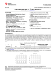
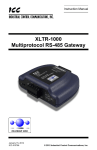
1.3 Configuring Site and Alert Data
Important:
Do not remove or insert the SD-Card from the BoilerNet Interface Controller while it is powered on.
Doing so could result in data loss, and/or corruption of the SD-Card.
The SD-Card must be writable (not "locked") while in use in the BIC II.
All system configuration data is stored in the "ibc" directory on the BIC II’s SD-Card.
Figure 1
V1.00.6
BoilerNet Interface Controller II
3
The site information must be entered into the "site.dat" file, and optionally the "alerts.dat" file before the
BoilerNet Interface Controller can be used. There are many text editors (WordPad®, for example) can be
used to edit these files (please note that Windows NotePad® cannot be used). A computer with an
appropriate operating system and a "SD" card slot is required. Most versions of Windows®, Linux®, or
MAC® O/S should have a text editor that can be used to edit the "site.dat" and "alerts.dat" files. The
example shown here is using Windows WordPad.
Please note that some versions of Windows, particularly XP, may not properly recognize the FAT partition
on the SD-Card. DO NOT allow Windows to format the SD-Card if a prompt to this affect appears.
Cancel the operation, and use a computer with a more current version of Windows (or another O/S) and
up-to-date drivers and service patches, that properly recognizes the SD-Card.
Important:
When editing the files:
Do not alter any characters before the "=" sign in each line.
Do not enter a "\" or any other non-standard characters into any of the fields.
Do not alter any file other than the "site.dat" file on the SD-Card.
The file name is case sensitive. Do not alter or rename it.
After saving the settings, you should use the "Safely Remove" option in your computer's operating
system (if available) before removing the SD-Card from your computer.
V1.00.6
BoilerNet Interface Controller II
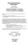
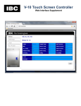
1.3.1
4
Configuring Site Data
When you open the "site.dat" file, it should appear similar to that shown in Figure 2 below.
Figure 2
Table 1 - "site.dat" Field Description
Field
1
2
3
4
5
6
7
8
9
10
Field Name
name
ipaddr
ipmask
ipgate
ipdns1
ipdns2
ntp
system_log
boiler_log
bacnet_id
Field Description
The site name
The IP address to be used (1)
The subnet mask (1)
The default gateway (1)
The primary DNS server (1)
The secondary DNS server (1)(2)
The ntp server (3)
Set to "1" to enable system logging, "0" to disable
Set to "1" to enable the boiler event logging, "0" to disable
The devices BACnet Identification number
11
bacnet_port
The BACnet port number (typically 47808)
12
13
14
15
web_enable
bacnet_enable
email_enable
reconfig
Set to "1" to enable the Web (Internet) interface, "0" to disable (5)
Set to "1" to enable the BACnet interface, "0" to disable (5)
Set to "1" to enable E-Mail Alerts, "0" to disable (6)
Set to "1" to save the setting to internal FLASH and then use the
new settings.
(4)
Max. Size
40
20
20
20
20
20
20
1
1
32 bit
integer
16 bit
integer
1
1
1
1
V1.00.6
BoilerNet Interface Controller II
5
(1) If a dynamic IP address is to be obtained from a DHCP server, then "ipaddr", "ipmask", "ipgate", "ipdns1", and "ipdns2"
should all be set to "0.0.0.0" (a dynamic IP address is generally not recommended).
(2) "ipdns2" is optional. Set to "0.0.0.0" if not used.
(3) If a ntp server is specified, then the BACnet Time Synchronization will not be used. To use the BACnet Time
Synchronization, the ntp server parameter should be set to "0.0.0.0". Note that the BIC will only use the first BACnet time
synchronization message it receives after it starts-up. Subsequent time-sync messages will be ignored.
(4) This feature is not implemented in V1.0 of the BoilerNet Interface Controller.
(5) Enable one or both of these options.
(6) The SMTP server information in the "alerts.dat" file must be configured before enabling this option.
Important: For the BIC II to use the new settings, you must set the "reconfig" flag to "1" before saving
the file. On start-up, the BIC II reads the "site.dat" file and checks the state of this flag. If
set, it copies these settings to its internal configuration registers, resets the flag, and then
starts the system using the new settings. Be sure to record the configuration settings, or
make a backup of the "site.dat" file if you alter it.
It will take approximately 3 to 4 minutes for the BIC II to restart when the settings have been altered.
V1.00.6
BoilerNet Interface Controller II
1.3.2
6
Configuring the Alert Data
The "Alert Data" contains the information for accessing a SMTP mail server, allowing E-Mail Alerts to be
sent in the event a problem with a boiler is detected. All site information is stored in the "alert.dat" file in
the "ibc" directory on the BIC’s SD-Card.
When you open the "site.dat" file, it should appear similar to that shown in Figure 4 below.
Figure 3
Table 2 - "alert.dat" Field Description
Field
1
2
3
4
5
6
7
Field Name
alert_from
alert_to
smtp_server
smtp_port
Field Description
E-Mail "from" name
E-Mail address the alert will be sent to
name or IP address of the SMTP mail server
SMTP server port to be used
smtp_authentication SMTP sever authentication type
smtp_login
SMTP server login name
smtp_password
SMTP server password
Max. Size
40
40
40
16 bit
integer
10
40
20
V1.00.6
BoilerNet Interface Controller II
7
2 SD-Card
The BoilerNet Interface Controller requires a standard Secure Digital Flash Card (SD-card) for operation.
Figure 4
The BIC II can support both "standard" and "SDHC" SD-Cards. A 2GB SD-card is more than sufficient for
the BIC's operation.
IBC will typically supply a SD-Card with the BIC. Please contact IBC if a new or replacement SD-Card is
required. The SD-Card is specially formatted with both a Windows compatible partition, and a "hidden"
partition that typically cannot be accessed by a Windows based computer. Do not reformat or repartition
the SD-Card.
Important:
Do not remove or insert the SD-Card from the BoilerNet Interface Controller while it is powered on;
doing so could result in data loss, and/or corruption of the SD-Card.
The BoilerNet Interface Controller will not function, or will stop functioning, if the SD-Card is not
present or is removed.
The SD-Card must be writable (not "locked") while in use in the BIC.
A card with a speed class of 4 or higher (minimum 4MB/second write speed) is required.
V1.00.6
BoilerNet Interface Controller II
8
3 Installation
The BoilerNet Interface Controller requires a Network (Ethernet) cable connection to the network it is to be
connected to, a BoilerNet twisted pair connection to the boilers, and a power source.
3.1 Location
Typically the BIC II will be installed in the same room as the boilers it will be interfacing to. It can also
usually be installed in a location remote to the boiler room if required. Note that the total length of the
BoilerNet twisted pair wire is limited, and is generally shorter than the permitted length of the network
(Ethernet) cable. Therefore, it is usually better to extend the network cable to BIC II’s location instead of
extending the BoilerNet twisted pair wiring to a remote location.
Also note that the maximum length of both the BoilerNet twisted pair and the network cable will vary
depending on the environmental conditions at your site. In general, keep all cable runs as short as
possible. Also try to keep data and power cables separated.
3.2 Power and Enclosures
The BoilerNet Interface Controller II requires a power source of 5VDC at 7.5 watts minimum. This is
typically supplied from a 120VAC switching power adapter; therefore there should be a 120VAC outlet
located reasonably close the where the BIC will be located. Other power supply options, including 100 to
240VAC are available, as well as Power over Ethernet (PoE).
The standard enclosure for the BoilerNet Interface Controller is not a NEMA rated enclosure, and
therefore it needs be located in a protected area away from moisture, temperature extremes, and dust.
NEMA rated enclosures for the BIC II can be supplied by IBC if required.
Please contact IBC Technologies for additional installation options and information.
V1.00.6
BoilerNet Interface Controller II
9
3.3 BoilerNet Connections
The BoilerNet Interface utilizes a 2-wire CAN-bus communications interface between the boilers and the
BIC II. BoilerNet wiring needs to be performed in accordance to published standards, such as ISO 11898
or SAE J2284.
A suitable cable, compliant with standards such as ISO 11898 or SAE J2284 must be used. The wiring
must also be installed in compliance with these standards.
Cerco Cable manufactures cable suitable for CAN-bus use. Cerco AT-HOM 29 #8320, or cable with
equivalent specifications from another cable manufacturer, must be used. The general specifications for
this cable are:
24 AWG shielded twisted pair
9 twists per foot
Capacitance 12.5pF/Ft (cond./cond.)
Resistance 25.5 ohms/1000'
Full specifications and information can be found on the Cerco web site: http://www.cercocable.com.
Please contact IBC if any additional information is required.
Figure 5
On the boiler's controller board, the "Boiler Net +" is the "CANH" connection, the other terminal is "Boiler
Net –", which is the "CANL" connection. On the BIC II terminal block, the red wire is the "Boiler Net +"
(CANH) connection; the white is the "Boiler Net –" (CANL) connection.
Please note that the BIC II has a 120 ohm CAN-bus terminator built into the controller board, which cannot
be disabled. Therefore, the BIC II must be wired in as either the first or last device in the BoilerNet
communications chain. The termination jumper (JA02) needs to be removed from all the boiler controller
boards with the exception of the first or last boiler of the BoilerNet chain. Please refer to Figure 6 below
for an example diagram.
V1.00.6
BoilerNet Interface Controller II
10
Figure 6
Please also refer to IBC document "Tech Memo 2310081 – Multiple Boiler Systems" for additional
information.
Important: The BoilerNet (CAN-bus) interface on both the BIC II and the boiler's controller can be
damaged by static electricity and other stray voltages and currents. Proper precautions must
be used when installing and handling the communications cable and wiring. DO NOT use a
continuity tester, or any other test equipment not specifically designed for use with CAN-bus
equipment, without first disconnecting all devices connected to the CAN-bus network. All
devices must also be powered off before connecting or disconnecting devices. Failure to do
so can result in damage to the BIC II and/or the boiler's controller board, which will not be
covered under warranty.
3.4 Configuring the Boilers
All the boilers that the BoilerNet Interface Controller is to interface with, and the BIC II itself, must be
connected to the same BoilerNet (twisted-pair) network. Every boiler needs to be assigned a unique
Boiler ID. This must be performed through the user interface on the boiler.
Typically the boilers will have been setup for Multi-Boiler operation with one boiler (usually Boiler ID: 1)
designated as the master. It is possible that the boilers will be operating independently, without a boiler
being designated as a master. In this case, each boiler must still be assigned a unique Boiler ID.
Note: Boiler firmware version 3.00.0 or newer is required for operation with the BoilerNet Interface
Controller. Please contact IBC if you boiler(s) require a firmware upgrade.
For more information regarding Multi-Boiler operations, please refer to IBC document "Tech Memo
2310081 – Multiple Boiler Systems". Also please consult the boiler's User Manual for information on
setting up and configuring your boiler(s).
V1.00.6
BoilerNet Interface Controller II
11
3.5 Operation
The BoilerNet Interface Controller’s operation is fairly straight forward. Insert the configured SD-Card into
the BIC II's SD slot, ensure the BoilerNet cables are connected, and if not using PoE, that the Ethernet
cable is connected. Then apply the power by connecting either the external 5VDC power supply, or if
using PoE, connect the Ethernet cable. You should see a green "power" light on the BIC II, as well as
activity on the network connector.
Important: Connect only one of the power sources to the BIC II. DO NOT use both the external 5VDC
power supply and PoE simultaneously; doing so may result in damage to the BIC II and/or
the power supplies.
If this is the first power-up of the BIC II for a new installation, then all the boilers that the
BIC II will be interfacing with need to be powered up and properly configured with a Boiler ID
before the BIC II is powered on. If a new boiler is ever added to the system, the BIC II will
need to be restarted before it will see the new boiler.
Note that it takes approximately 2 minutes for the BoilerNet Interface Controller II to initialize before the
BACnet or web interfaces will be available. For a first time start-up, or if Network and/or BACnet settings
have been changed, the start-up time will be approximately 4 minutes.
V1.00.6
BoilerNet Interface Controller II
12
4 Web (HTML) Interface
Once each Boiler has been assigned a Boiler ID through the boiler’s control panel, all other settings for the
boiler can configured using the BoilerNet Interface Controller’s Web Interface. Multiple individual boilers
can also be monitored simultaneously.
The Web Interface screens generally mirror the screens available through the boiler's controller LCD
screen and keypad. Please refer to user manual for your boiler for a description of all the individual fields
and their values. This manual assumes that the user is experienced in the setup and use of IBC boilers,
and boiler systems and installations in general.
Most standard web browsers, such as Mozilla Firefox®, Microsoft Internet Explorer®, or Google Chrome®,
can be used for accessing the BIC’s Web Interface. Typically the IP address assigned to the BIC II will be
entered directly (as shown in Figure 7), though this may vary depending on the configuration of your
network.
The BIC II's Web Interface requires the use of cookies, so you will need to configure your web browser to
allow cookies for the BIC II's "site" address. You may need to configure your browser to allow pop-up
windows for the BIC II as well. Most browsers can also be configured to display a new window as either a
"window" or a "tab", depending on your personal preference (the examples here are shown as "tabs").
V1.00.6
BoilerNet Interface Controller II
13
Figure 7
Only basic information regarding the BoilerNet system will be initially displayed on the opening screen.
You must "Login" using a valid user name and password to be able to access and alter detailed
information regarding the BIC II and the individual boilers on the network.
Some Web Interface screens may not be available to a user, depending on the security level that they
have been assigned. Other screens may be viewable, but altering and saving setting values will not be
permitted.
V1.00.6
BoilerNet Interface Controller II
14
The Web Interface and the boiler's screen and keypad should not be used simultaneously for entering or
altering settings. If a key on the boiler's keypad is pressed, then the Web Interface will be "locked out" for
a period of 2 minutes from the last key press; the operator at the boiler is given control. Viewing of
settings using the Web Interface will still be permitted, but any settings changed using the Web Interface
will not be saved until the lock-out period has expired. Note that the lock-out will apply to all web screens,
regardless of the screen the boiler or the Web Interface happens to be on at the time.
It is highly recommended that you log out of, or close, the BoilerNet Web Interface when it is not actually in
use.
V1.00.6
BoilerNet Interface Controller II
15
4.1 User Passwords
The Web Interface employs a password system to control access. Up to 10 User Accounts can be
configured.
Figure 8
Note that both the "User ID" and "Passwords" are case sensitive, both on this screen and when logging in
using the Web interface.
To add or change an entry, click the "Update" box for that entry first, then add or change the entry's data.
When all the desired updates have been done, click "Save". The User information will be saved by the
system, and the web page will be updated to reflect the changes.
V1.00.6
BoilerNet Interface Controller II
16
Table 3 – Security Levels
Level
View
Operator
Supervisor
Installer
Description
View access only; access to certain screens is restricted
Equivalent to the "User" access level on the boiler's controller
View access to all screens, write access to all but "advanced" functions
Full read/write access to all screens and functions
Generally, the "View" and "Operator" levels should be assigned to most users. "Supervisor" and "Installer"
levels should only be assigned to select personnel.
There are 2 default User ID's that will have been factory configured. User ID "ibc" is the default for all
operations, while User ID "BACnet" is for any BACnet operations that require a password. The password
for both ID's is set to "boiler" from the factory.
The "ibc" User ID cannot be deleted. It is however strongly recommended that the default password be
changed before the BIC is put into actual operation.
The "BACnet" User ID is required for any BACnet operations that use a password. Note that the security
level is not relevant for BACnet operations; the presence of the "BACnet" User ID and correct password
are what are required. If the BACnet interface is not being used, then this User ID can also be deleted if
desired. It is also strongly recommended that the default password be changed before the BIC II is put
into actual operation.
V1.00.6
BoilerNet Interface Controller II
17
4.2 Site Data
The "Site Data" screen allows all the information in the "site.dat" file to be configured. Note that this
screen is not accessible until after an IP address has been initially assigned through editing the "site.dat"
file, and the BoilerNet Interface controller is up and running. Please refer to "1.3 - Configuring Site and
Alert Data" for more information.
Figure 9
V1.00.6
BoilerNet Interface Controller II
18
Note that for all fields except "Site Name", "Display Units", "E-Mail Alerts", "System Logs", and
"Boiler Logs", the BoilerNet Interface Controller will need to be rebooted before the changes will
take effect.
Setting the "Reboot BoilerNet Controller" to "Yes" will cause the controller to reboot after the
"Save" button is clicked.
If you are rebooting the IBC, make sure that it is not in use by anyone else before it is rebooted. It
will take approximately 3 to 4 minutes for the BIC II to reboot when network or BACnet settings are
altered.
If "Metric" is selected for the "Display Units", values will be displayed as °C, meters, and kPa as
appropriate. If "Imperial" is selected, values will be displayed as °F, feet, and psi. Note that the
"Display Units" field only affects the units displayed on the Web Interface. The settings on neither
the individual boilers nor the BACnet interface are altered. Any open Web Interface pages will
need to be "reloaded" before the new unit setting will take effect.
If the IP address was changed, the new IP address will need to be used to access the BIC II again
for both the Web and BACnet interfaces after the reboot has completed.
The IP settings should only be changed on the advice of your Network Administrator. Using
incorrect IP or BACnet parameters could cause the BIC II to become inaccessible, and could also
affect the operation of other devices on the network.
Before enabling the "E-Mail Alerts", the E-Mail Alert data must be configured first; refer to section
"4.3 - Alert Data".
V1.00.6
BoilerNet Interface Controller II
19
4.3 Alert Data
The BIC II can be configured to send an E-Mail alert when a problem is detected with a boiler. This screen
allows the information in the "alert.dat" file to be configured, which contains the information for the SMTP
server to be used for sending the E-Mail through.
Figure 10
Please contact your System Administrator or your Internet Service Provider for the information required for
accessing your SMTP Mail Server (hint: you may be able to find this information in the "Account Settings" for
your E-Mail client).
Once the SMTP server information is configured, the "E-Mail Alerts" option must be enabled in the "Site Data"
screen; refer to section "4.2 - Site Data".
V1.00.6
BoilerNet Interface Controller II
20
4.4 Site Log
This is the event log for the BoilerNet Interface Controller. This displays events for the BIC II itself. For the
logs for the individual boilers, please refer to sections "4.14 - Boiler Logs" and "4.15 - Boiler Error Logs".
Figure 11
V1.00.6
BoilerNet Interface Controller II
21
4.5 System Status Display
An example of the System Status Display is shown below:
Figure 12
Note that in this example there is a
boiler in the system.
* after Boiler 01; this indicates that this boiler is the "Master"
V1.00.6
BoilerNet Interface Controller II
22
If there is no master boiler in the system, then "Boilers Responding" and "Boilers Firing" are not
applicable, and "Target", "Actual", "Outdoor" and "Indoors" temperatures will be displayed from the
first online boiler in the list.
If a Boiler is shown in red (e.g. Boiler 01), this indicates that there is an Error or Warning message
present for that boiler. Clicking the boiler will take you to the Boiler Status Display, where you will
be able to see any Error and/or Warning messages, along with a detailed status display for the
boiler.
V1.00.6
BoilerNet Interface Controller II
23
4.6 Boiler Status Display
This is the main status of an individual boiler on the network. All settings and information regarding the
boiler is subsequently accessed from this screen.
Figure 13
V1.00.6
BoilerNet Interface Controller II
24
4.7 User Settings
Figure 14
V1.00.6
BoilerNet Interface Controller II
25
4.8 Setbacks
Figure 15
Note that the boiler's use of the setbacks is controlled on the "4.7 - User Settings" screen.
V1.00.6
BoilerNet Interface Controller II
26
4.9 Installer Settings
Figure 16
To alter the "Load Type" for a load, select the desired Load Type from the pull-down box, then
select "Save". Once the "Load Type" is set to the desired type, you can then edit the settings for
the load.
Do not alter the load settings before changing the "Load Type". Changing the "Load Type" may
set some of the values for the load back to the system default value, and your altered settings will
be lost.
V1.00.6
BoilerNet Interface Controller II
27
Whenever the "Load Type" is altered, always verify that the settings for the load are indeed correct
for your system. As previously mentioned, if the "Load Type" is altered, some of the Load Settings
may be reset to the system default values.
V1.00.6
BoilerNet Interface Controller II
28
4.10 Load Settings
An example of the screen for a "Reset Heating" load is shown below. The actual fields displayed will vary
by the Load Type selected. If the Load Type is altered through "4.9 - Installer Settings", always verify
that the load settings are in fact correct for your system.
Figure 17
V1.00.6
BoilerNet Interface Controller II
29
4.11 Multi-Boiler Settings
Figure 18
V1.00.6
BoilerNet Interface Controller II
30
4.12 Cleaning Information
Figure 19
When the boiler has been cleaned, select "Yes" from the "Boiler Cleaned" pull-down, and then click
"Save". The "Cleaning Counter" will then be reset, and the "Last Cleaned" date updated.
The cleaning intervals are factory set, but can be adjusted by your installer for your site conditions
and/or requirements.
V1.00.6
BoilerNet Interface Controller II
31
4.13 Diagnostics
This screen is intended for use by, or on the advice of, IBC or other qualified service personnel only.
"Supervisor" or higher security rights are required to access this screen. Do not alter any value on this
screen unless directed to do so by IBC technical personnel.
Figure 20
V1.00.6
BoilerNet Interface Controller II
32
4.14 Boiler Logs
Figure 21
Note that in this particular example, the boiler was not configured for a Remote Load; therefore the
"Remote On-Time" is zero.
V1.00.6
BoilerNet Interface Controller II
33
4.15 Boiler Error Logs
Each boiler maintains a log of the last 8 "event" and "watchdog" errors that have occurred on it. The
information in the logs is mainly intended for use by IBC service personnel. If you notice errors are frequently
occurring, you should contact your installer or IBC service personnel. This may indicate a site problem that
needs to be addressed, or a setting in the boiler that needs to be adjusted. Also refer to section "4.4 - Site
Log", which may indicate other site issues which could require attention.
Figure 22
V1.00.6
BoilerNet Interface Controller II
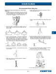
34
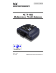
4.16 Run Profile
This screen provides a graphical summary of the time the boiler used servicing each of the Loads, as well as
the modulation (or throttle) percentage being used while servicing each of the individual loads.
Figure 23
In the above example, the boiler spent 9% of its "Burner On" time servicing Load #1; 23% of its
time servicing Load #2; and 67% of its time servicing Load #3.
Of the time it spent servicing Load #1, 12% of that time was at 10% modulation (throttle); 33% was
at 20% modulation, etc.
In this particular example, the boiler was not configured for a Remote Load; therefore all the
Remote Load values are zero.
Note that due to rounding in the calculations, the totals may not add up to exactly 100%.
V1.00.6
BoilerNet Interface Controller II
35
5 BACnet Interface
The BoilerNet Interface Controller provides BACnet "Server" functionality over a BACnet/IP interface.
To make use of the BIC II's BACnet capabilities, a properly configured BACnet Operator's Workstation or
BACnet Web Server software package is required. The BoilerNet Interface Controller has been tested
using the Reliable Controls® RC-Studio Operator’s Workstation V2.0 release 1.54, though any certified
BACnet Operator Workstation (B-OWS) or BACnet server software package should work as well.
5.1 Site Requirements
Please refer to section "3 - Installation" for site installation requirements. Site parameters also must be
setup correctly; refer to section "1.3 - Configuring Site and Alert Data".
It should be noted that the BIC II does not provide any BBMD, foreign device, or other BACnet routing
support. Please contact your Network Administrator or your BACnet Systems Integrator for more
information and assistance.
A properly configured BACnet Operators Workstation or BACnet Web Server software package is required
to access the BoilerNet Interface Controller's BACnet features.
V1.00.6
BoilerNet Interface Controller II
36
An example of a BACnet object list obtained from a BoilerNet Interface Controller is shown below:
Figure 24
V1.00.6
BoilerNet Interface Controller II
37
An example of the sort of customized display that can be setup for use with your B-OWS software
package is shown below:
Figure 25
Of course, much more elaborate system and status displays can be developed. The actual configuration
and use of the BACnet Operator Workstation software will be specific to your site and your software
package.
The integration of the BoilerNet Interface Controller and the IBC boilers into a new or existing BACnet
installation will be dependent on your particular site and the BACnet software package(s) you are using,
and therefore beyond the scope of this document. Any questions regarding the use and setup of the
BACnet software package you are using, and the integration of the BACnet objects provided by the BIC II
into your BACnet system should be referred to the manufacturer of your BACnet workstation or server
software, your Network Administrator, or your BACnet System Integration and Support organization.
V1.00.6
BoilerNet Interface Controller II
38
5.2 BACnet Objects
The BoilerNet Interface Controller will provide a set of BACnet objects for each boiler on the network. There
is also set of "Master" objects, which are associated with the boiler designated as the "Master" boiler.
Any BACnet object commands that require a password (e.g. the "Reinitialize Device" command), will use
the password that has been setup for the "BACnet" user id. Please refer to "4.1 - User Passwords" for
information on setting up the BACnet User Id.
Table 4 – Boiler Objects
Object Name
Value
Units
Object ID
Boiler 1 Supply Temp.
22
°C
AI1001
Boiler 1 Return Temp.
23
°C
AI1002
Boiler 1 Secondary Temp.
22
°C
AI1003
Boiler 1 DHW Temp.
60
°C
AI1004
Boiler 1 Outlet Pressure
5.6
psi
AI1005
Boiler 1 Inlet Pressure
5.7
psi
AI1006
Boiler 1 Flow Rate
0
Gal/min
AI1007
Boiler 1 Fan Speed
0
revs/min
AI1008
Commandable
Notes
"SL" models excluded
Boiler 1 Fan Pressure
102
AI1009
Boiler 1 Offset Pressure
102
AI1010
Boiler 1 Stack Temp.
70
°C
AI1011
Boiler 1 MBH
0
btus/hr
AV1001
Boiler 1 Power On Hours
792
hrs
AV1002
Boiler 1 Burner On Hours
100
hrs
AV1003
Boiler 1 Load 1 On Hours
50
hrs
AV1004
Boiler 1 Load 2 On Hours
25
hrs
AV1005
Boiler 1 Load 3 On Hours
25
hrs
AV1006
Boiler 1 Ignition Starts
99
AV1007
Boiler 1 Ignition Trials
6
AV1008
Boiler 1 Load 1 Cycles/Day
10
AV1009
Boiler 1 Load 2 Cycles/Day
5
AV1010
Boiler 1 Load 3 Cycles/Day
5
AV1011
Boiler 1 Delta Pressure
0
AV1012
154
AV1013
Boiler 1 Var Speed Duty Cycle
0
AV1014
Boiler 1 Remote On Hours
0
hrs
AV1015
Boiler 1 Outdoor Temp.
5
°C
AV1016
1
Boiler 1 Indoor Temp.
21
°C
AV1017
1
Boiler 1 Required Pressure
If equipped
"SL" models excluded
V1.00.6
BoilerNet Interface Controller II
Object Name
39
Value
Units
Object ID
Commandable
Boiler 1 Supply Setpoint
60
°C
AV1018
1
Boiler 1 Remote Input
50
%
AV1019
Boiler 1 Inlet/Outlet Sensor
OK
BV1001
Boiler 1 Remote Loop Sensor
OK
BV1002
Boiler 1 Cleaning Required
No
BV1003
Boiler 1 Anti-Cycling
Not Active
BV1004
Boiler 1 Short Cycling
Not Active
BV1005
Boiler 1 Comm. Status
Online
BV1006
Boiler 1 Master Boiler
Yes
BV1007
Boiler 1 Primary Pump
Off
BV1008
Boiler 1 P/V 1
Off
BV1009
Boiler 1 P/V 2
Off
BV1010
Boiler 1 P/V 3
Off
BV1011
Boiler 1 Occupied
Yes
BV1012
2
Boiler 1 Setback 1
Disabled
BV1013
2
Boiler 1 Setback 2
Disabled
BV1014
2
Boiler 1 Setback 3
Disabled
BV1015
2
Boiler 1 Enable
Enabled
BV1016
2
Boiler 1 Thermostat 1
On
BV1017
1
Boiler 1 Thermostat 2
Off
BV1018
1
Boiler 1 Thermostat 3
Off
BV1019
1
Standby
MV1001
Boiler 1 Error Message
None
MV1002
Boiler 1 Service Mode
Normal
MV1003
2
Boiler 1 Boiler Model
45-225
MV1004
Boiler 1 Load 1 Type
Set Point
MV1005
2
Boiler 1 Load 2 Type
Off
MV1006
2
Boiler 1 Load 3 Type
Off
MV1007
2
Boiler 1 Operating Status
Notes
V1.00.6
BoilerNet Interface Controller II
40
Table 5 – Master Objects
Object Name
Value
Units
Object ID
Commandable
Notes
Master Target Temp.
22
°C
AI1101
Master Actual Temp.
22
°C
AI1102
Master Boilers Responding
4
AV1101
Master Boilers Firing
1
AV1102
Master Outdoor Temp.
10
°C
AV1103
1
Master Indoor Temp.
21
°C
AV1104
1
Master Supply Setpoint
60
°C
AV1105
1
A master boiler must be defined in the system for these objects to be available.
Table 6 – Miscellaneous Objects
Object Name
Value
IBC BoilerNet
Units
Object ID
Commandable
Notes
DEV
1) If BACnet communications is lost for a period of 5 minutes, then these objects will revert to their noncommanded (relinquish) values.
2) Altering the object's value will alter the saved value in the boiler's controller; sending a relinquish
command or a loss of BACnet communications will not restore the setting to its previous state.
Values shown are examples only.
Each boiler in the network will have its own list of "Boiler Objects"; Boiler #1 only is shown in the above
example.
For any commandable objects, note that if there is operator activity on the boiler's keypad, then BACnet
"write" commands for these settings will be locked out for 2 minutes after the last key press. This is to
prevent conflicting operations between an operator on-site working on the boiler, and a remote
operator.
The "Object ID" will be dependent on the BACnet software package you are using (the examples above
are generated by the Reliable Controls® Operator's Workstation).
The actual "Object ID" numbers will be site specific.
Additional objects may be available, depending on the boiler and BIC II firmware versions in use and
the configuration of the equipment at your site.
Certain objects may or may not be available depending on the boiler model and the firmware version
installed.
V1.00.6
BoilerNet Interface Controller II
41
5.3 Multi-value Objects
Table 7 – MV1001 – Operating Status
1
2
3
4
5
6
7
8
9
10
Standby
Purging
Igniting
Heating
Circulating
Error
Initialize
Service
Restart
Unknown
Table 8 – MV1002 – Error Message
1
2
3
4
5
6
7
8
9
10
11
12
13
14
15
16
17
None
Water High Limit Exceeded
Vent High Limit Exceeded
Ignition Failure
Aux. Interlock 1 Open
Aux. Interlock 2 Open
Low Air Flow
No Water Flow
Low Water Pressure
Inlet Pressure Sensor
Outlet Pressure Sensor
Ignition Module
AC Crossing Error
Max. In-Out Temp. Exceeded
Loop/Indoor Sensor
Water High/Low Cutout
Vessel/Vent High Limit
Table 9 – MV1003 – Service Mode
1
2
3
Normal Operation
Service Standby
Restart
V1.00.6
BoilerNet Interface Controller II
42
Table 10 – MV1004 – Boiler Model
1
2
3
4
5
Unknown
15-150
45-225
80-399
20-115
Table 11 – MV1005, MV1006, MV1007 – Load Type
1
2
3
4
5
6
7
Off
DHW
Reset Heating
Set Point
External Control
Manual Control
DHW Loop 2
V1.00.6
BoilerNet Interface Controller II
43
6 Enclosure Installation Notes
Please note that it is the responsibility of the installer to adhere to any electrical code requirements
which may be applicable to the installation of this equipment. The installation must be performed
only by qualified service personnel.
The enclosure will need to be modified by the installer for routing the power and communications
wiring to the electronic components.
Please note that any damage to the BIC II, the boiler's controller board, or any other equipment
connected directly or indirectly to the system caused by improper handling, installation, or wiring will
not be covered by warranty, and is the sole responsibility of the installer.
The electronics modules (control boards) can be damaged by static-electric discharge; anti-static
precautions must be used when handling. If the electronics module is mounted to a backplane, then
handle the electronics assembly by the metal back-panel only; avoid touching the electronics
module itself.
Remove the electronics module from the enclosure before making any modifications to the
enclosure. If the control board is mounted on a back plane, remove the entire backplane; leave the
control board mounted on the backplane.
Be sure to put the electronics assembly in a safe place while making the enclosure modifications; in
an anti-static bag if possible.
The AC supply lines should be separated from the BoilerNet twisted pair and the Ethernet wiring to
prevent possible electrical interference to the network wiring. The use of shielded cables is
generally recommended.
IMPORTANT: Be sure to remove and thoroughly clean all metal filings from the enclosure after the
modifications have been made.
When possible, the enclosure should be mounted in position before remounting the electronics
assembly in the enclosure.
Please refer to sections "3.3 - BoilerNet Connections" and "3.4 - Configuring the Boilers" for additional
information regarding the BoilerNet wiring.
V1.00.6
BoilerNet Interface Controller II
44
7 Troubleshooting Notes
As mentioned in section "3.3 BoilerNet Connections", BoilerNet uses a CAN-bus interface for
communicating between the boilers and the BIC II. The wire type and installation must comply with
CAN-bus standards such as ISO 11898 and/or SAE J2284.
Again referring to section "3.3 BoilerNet Connections", the terminators must be removed from the
middle boilers, and the wire polarity must be correct at all the boilers and the BIC II. The BIC II must be
on the end of a BoilerNet communications chain.
All boilers must be powered on and have a unique Boiler ID assigned to them before the BIC II is
powered on. The BIC II checks for the on-line boilers as it starts up.
Make sure there is only one boiler configured as the master (typically boiler #1). The boilers will not
function correctly if there is more than one boiler assigned as the master, and the BIC II will not
properly recognize the boilers.
Very occasionally, the boilers need to be power cycled after the boiler ID’s and master boiler have been
assigned. Turn off all the boilers and the BIC II, then power on the boilers one at a time, starting with
the master; power on the BIC II last.
The BIC II uses BACnet/IP; not BACnet Ethernet. Check that the BACnet devices you are interfacing
to are configured correctly.
A BACnet BBMD routing device is required if interfacing BACnet devices on different network segments
and/or subnets. Most standard routers will not properly route BACnet/IP packets.
Check that the correct firmware version is on each boiler; it needs to be at least V3.00.0 or newer, and
all boilers should have the same firmware version installed. (Hint: the firmware version is displayed as
the boiler powers up, and also in the "Installer Setup" – "System Information" screen in V3 firmware.)
On the “Master Boiler”, go into the “Advanced Diagnostics" menu; near the bottom of this screen it will
show “Net. Boilers Online”, which should be the number of boilers installed at your location. If this does
not match, then this typically indicates a BoilerNet wiring problem or that a boiler has not been assigned
a Boiler ID. Also check the "Net. Boilers Available". This should also equal the number of boilers at
your site, unless a boiler is servicing a local heat call and has "Opted Out".
In V3.00.7 or newer firmware, the communications status with the BIC will also be displayed in the
"Advanced Diagnostics" menu.
Make sure the header is properly attached to the BIC II controller card.
V1.00.6
BoilerNet Interface Controller II
45
8 Bootloader Configuration
This is an optional step that will shorten the start-up time of the BIC II controller board in some specific
situations.
A bootloader comes pre-installed in the controller's Flash memory, which is a customized version of U-Boot.
U-Boot has several environment variables which it uses, which are also saved in the controller's Flash
memory. One of these environment variables can be altered to reduce the start-up time in some particular
cases.
It should be noted that not altering this environment variable will not affect the operation of the BIC II; it only
shortens the start-up time in some particular installations. In an installation with no DHCP server present and
accessible to the BIC II, the start-up time will go from approximately 1 minute and 15 seconds to approximately
4 minutes and 30 seconds if this environment variable is not altered.
Setting the U-Boot Environment Variable
A terminal program, such as Hyper-terminal, or another "standard" terminal program, is needed, in
additional to a RS232 serial port on the computer being used.
Connect a "null" modem cable between the computer and the BIC II controller board.
Set the appropriate serial port on the computer to 115,200 bpi, 8 data, 1 stop, no parity, and (typically)
no handshaking.
Apply power the to BIC II (or press the "reset" button). You should see something similar to the
following on the screen:
V1.00.6
BoilerNet Interface Controller II
46
Texas Instruments X-Loader 1.46 (Nov 29 2010 - 23:10:41)
Starting OS Bootloader...
U-Boot 2009.11-00005-ge83d2db (Dec 07 2010 - 11:55:34)
OMAP34xx/35xx-GP ES1.0, CPU-OPP2 L3-165MHz
Craneboard + LPDDR/NAND
I2C: ready
DRAM: 256 MB
NAND: 256 MiB
In: serial
Out: serial
Err: serial
Die ID #0b96000100000000015da3961501701e
Net: davinci_emac_initialize
Ethernet PHY: GENERIC @ 0x00
EMAC LSB = 0x001066dd
EMAC MSB = 0x00080028
----------------------------EMAC ID 08:00:28:10:66:dd
----------------------------DaVinci EMAC
Hit any key to stop autoboot: 0
Press any key within 3 seconds to enter the bootloader configuration menu. You then see the prompt:
AM3517_CRANE #
Type, or preferably copy and paste, the following line (all one line):
setenv mmcargs setenv bootargs console=${console} root=/dev/mmcblk0p2 rw rootfstype=ext3 rootwait eth=${ethaddr}
Press the "enter" key once the line is entered; you should then get the "AM3517_CRANE # " prompt
again.
Enter the following command, again followed the the "enter" key:
saveenv
You should then see something similar to this displayed:
Saving Environment to NAND...
Erasing Nand...
Erasing at 0x260000 – 100% complete.
Writing to Nand... done
AM3517_CRANE #
V1.00.6
BoilerNet Interface Controller II
47
Enter the following command, followed by the "enter" key:
printenv
You should see something similar to the following:
printenv
bootcmd=if mmc init; then if run loadbootscript; then run bootscript; else if run loaduimage; then run mmcboot; else
run nandboot; fi; fi; else run nandboot; fi
bootdelay=3
baudrate=115200
bootfile=uImage
loadaddr=0x82000000
console=ttyS2,115200n8
nandargs=setenv bootargs console=${console} root=/dev/mtdblock4 rw rootfstype=jffs2 eth=${ethaddr} ip=dhcp
loadbootscript=fatload mmc 0 ${loadaddr} boot.scr
bootscript=echo Running bootscript from mmc ...; source ${loadaddr}
loaduimage=fatload mmc 0 ${loadaddr} uImage
mmcboot=echo Booting from mmc ...; run mmcargs; bootm ${loadaddr}
nandboot=echo Booting from nand ...; run nandargs; nand read ${loadaddr} 480000 500000; bootm ${loadaddr}
dieid#=0b96000100000000015da3961501701e
ethact=DaVinci EMAC
filesize=F40000
serverip=192.168.1.8
ipaddr=192.168.1.9
ethaddr=08:00:28:10:66:dd
mmcargs=setenv bootargs console=ttyS2,115200n8 root=/dev/mmcblk0p2 rw rootfstype=ext3 rootwait
eth=08:00:28:10:66:dd
Environment size: 948/131068 bytes
AM3517_CRANE #
The line starting with "mmcargs" is the one to check. The numbers after "eth=" will be different, and
most importantly, the line should not end with "ip=dhcp".
The BIC II environment variables are now configured, and the controller board is ready for use again.
Hit the reset button, or disconnect and reconnect the power.
V1.00.6
BoilerNet Interface Controller II
48
9 Technical Specifications
Processor
600MHz ARM Cortex A8
Memory
256MB RAM
256MB Flash
File system via SD Flash card for data collection and future applications; 2GB minimum with SDHC support.
Power Requirements
Controller board: 5VDC @ 7.5W
120VAC and 100 to 240 VAC power supply options are available
Power Over Ethernet (PoE) capable
Enclosures
NEMA and standard enclosure options are available
Communications
IEEE 802.3 Ethernet 10/100 Base-T interface
TCP/IP v4 (v6 capable)
BACnet/IP via Ethernet interface
BoilerNet 2-wire interface via CAN-bus supports up to 24 IBC boilers
Features
Web Server for IBC BoilerNet
BACnet/IP Server for IBC boilers
FTP and Telnet Services
V1.00.6