1
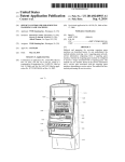
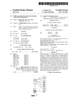
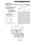
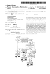
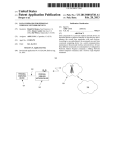
US008558935B2
(12) United States Patent
(10) Patent N0.:
(45) Date of Patent:
Yim et a1.
(54)
(58)
SCENE INFORMATION DISPLAYING
Field of Classi?cation Search
See application ?le for complete search history.
(56)
References Cited
U.S. PATENT DOCUMENTS
(75) Inventors: Hyun-ock Yim, SuWon-si (KR); Ung-sik
Kim, SuWon-si (KR); Jong-sun Kim,
SuWon-si (KR)
5,537,528 A *
7,271,838 B2 *
2003/0112361
(73) Assignee: Samsung Electronics Co., Ltd.,
SuWon-si (KR)
Notice:
Subject to any disclaimer, the term of this
patent is extended or adjusted under 35
U.S.C. 154(b) by 437 days.
(30)
(51)
Bean et a1.
. ... ... ...
2005/0270397
A1*
12/2005
Battles
. . . . ..
348/33301
2006/0192879
A1*
8/2006
Hisamatsu
.. ...
. . . . ..
348/33301
2007/0065137
A1*
3/2007
Hara et a1.
.. ...
. . . . . . . . . ..
2009/0073285 A1*
3/2009
Terashima ............. .. 348/231.99
2009/0103888 A1*
2009/0237548 A1*
4/2009 Murabayashi et a1. ....... .. 386/52
9/2009 Watanabe et a1. ...... .. 348/33302
.. ... ..
348/364
396/291
ABSTRACT
(KR) ...................... .. 10-2008-0114850
information, probabilities that the determined scene corre
sponds to respective scene modes are calculated, and a scene
information identi?er including the probabilities for the scene
modes is generated and displayed. Thus, users may be
(2006.01)
informed of all applicable scene modes for a current image.
us. c1.
USPC
. . . . . ..
..... .. 345/211
In exemplary scene information displaying apparatus and
methods, scene information is detected from an input image,
a scene for the input image is determined by using the scene
Int. Cl.
H04N5/222
(52)
6/2003
12/2003
(57)
May 20, 2010
Foreign Application Priority Data
Nov. 18, 2008
Cooper
A1*
2003/0222867 A1*
(74) Attorney, A gent, or Firm * Drinker Biddle & Reath
LLP
Prior Publication Data
US 2010/0123815 A1
Takahashi et a1. .......... .. 715/255
Suekane et a1. ........ .. 348/33302
Primary Examiner * Justin P Misleh
Nov. 17, 2009
(65)
7/1996
9/2007
* cited by examiner
(21) App1.N0.: 12/619,789
(22) Filed:
Oct. 15, 2013
None
METHOD AND APPARATUS AND DIGITAL
PHOTOGRAPHING APPARATUS USING THE
SCENE INFORMATION DISPLAYING
METHOD AND APPARATUS
(*)
US 8,558,935 B2
22 Claims, 8 Drawing Sheets
............................... .. 348/333.02; 348/333.11
MACRO
PHOTOGRAPHING
MODE
LANDSCAPE MODE
PORTRAIT MODE
TRIPOD PHOTOGRAPHING MODE
BACKLIGHT PORTRAIT MODE
BACKLIGHT MODE
NIGHTPVIEW
PORTRAIT MODE
85%
BACKLIGHT MODE 70%
US. Patent
Oct. 15, 2013
Sheet 1 of8
US 8,558,935 B2
100
20
/
IVIANIPULATION
UNIT
10
OPTICAL
UNIT
15
7O
30
IMAGING
DEVICE
RROGRAM
STORAGE UNIT
16
IMAGING DEVICE
CONTROL UNIT
40
11
OPTICAL
ORIvING
UNIT
DSP
BUFFER
STORAGE UNIT
50
DATA
STORAGE UNIT
60
DISPLAY CONTROL UNIT
63
61
DATA DRIVING UNIT
SCAN
DRIVING
UNIT
DISPLAY UNIT
US. Patent
0a. 15, 2013
Sheet 2 of8
US 8,558,935 B2
FIG. 2
70
A
72
IMAGE SIGNAL
PROCESSING UNIT
73
71
CONTROL UNIT
SCENE INFORMATION
DETECTION UNIT
74
SCENE
DETERMINATION UNIT
75
SCENE INFORMATION
IDENTIFIER GENERATION UNIT
US. Patent
0a. 15, 2013
Sheet 3 of8
<m.UE
tPIQ m m<QkoEg
US 8,558,935 B2
US. Patent
0a. 15, 2013
mm.0;
mQOE
Sheet 4 of8
US 8,558,935 B2
US. Patent
0a. 15, 2013
Sheet 5 of8
US 8,558,935 B2
HM$IQ50Z“2m
In_
US. Patent
0a. 15, 2013
Sheet 6 of8
US 8,558,935 B2
FIG. 4
I START I
I
DISPLAY PREVIEW SCREEN
¢~4OO
I
DETECT SCENE INFORMATION FROM
IMAGE OF PREVIEW SCREEN
IS SCENE
INFORMATION TO BE
DISPLAYED ?
¢~402
404
, YES
DETERMINE WHICH SCENE PREVIEW
- 406
IMAGE BELONGS TO, BASED ON
DETECTED SCENE INFORMATION
I
GENERATE SCENE INFORMATION IDENTIFIER ¢~408
I
DISPLAY SCENE INFORMATION IDENTIFIER
I
END
¢~4IO
US. Patent
Oct. 15, 2013
Sheet 7 of8
US 8,558,935 B2
FIG. 5
I START I
DETECT SCENE INFORMATION
FROM INPUT IMAGE
IS SCENE
INFORMATION TO BE
DISPLAYED ?
"500
502
YES
DETERMINE WHICH SCENE INPUT
IMAGE BELONOS TO, BASED ON
DETECTED SCENE INFORMATION
"504
OENERATE SCENE INFORMATION
I~ 506
IDENTIFIER
DISPLAY SCENE INFORMATION
/~ 508
IDENTIFIER
514
SET AUTOMATIC
PHOTOGRAPHING
CONDITIONS
SPECIFIC SCENE
MODE BEEN SELECTED FROM
DISPLAYED SCENE INFORMATION
IDENTIFIER '2
510
SET PHOTOGRAPHING CONDITIONS
FOR SELECTED SCENE MODE
»5I2
PERFORM PI-IOTOGRAPHIC OPERATION
*516
END
US. Patent
0a. 15, 2013
Sheet 8 of8
US 8,558,935 B2
I START I
SELECT PLAYBACK MODE
I~6OO
SELECT IMAGE WHICH IS
TO BE PLAYED BACK
¢~602
IS SCENE
INFORMATION ABOUT
SELECTED IMAGE TO BE
DISPLAYED ?
604
610
DISPLAY ONLY
SELECTED IMAGE
EXTRACT SCENE INFORMATION
IDENTIFIER CORRESPONDING TO
SELECTED IMAGE
¢~606
DISPLAY SCENE INFORMATION IDENTIFIER ¢~608
TOGETHER WITH SELECTED IMAGE
END
US 8,558,935 B2
1
2
SCENE INFORMATION DISPLAYING
METHOD AND APPARATUS AND DIGITAL
PHOTOGRAPHING APPARATUS USING THE
SCENE INFORMATION DISPLAYING
METHOD AND APPARATUS
The scene information identi?er may include information
of at least tWo scene modes.
The at least tWo scene modes may be determined according
to the probabilities.
The at least tWo scene modes may include a portrait mode,
a night-vieW portrait mode, a landscape mode, a night-vieW
landscape mode, a macro photographing mode, a tripod pho
tographing mode, a backlight mode, or a backlight portrait
CROSS-REFERENCE TO RELATED PATENT
APPLICATION
mode.
The scene information displaying method may further
include setting a photographing condition for a scene mode
This application claims the priority bene?t of Korean
Patent Application No. 10-2008-0114850, ?led on Nov. 18,
2008, in the Korean Intellectual Property O?ice, the disclo
sure of Which is incorporated herein in its entirety by refer
selected by a user from among the at least tWo scene modes.
ence.
BACKGROUND
1. Field of the Invention
The present invention relates to image signal processing,
and more particularly, to a scene information displaying
method and apparatus in Which information about a scene that
a user desires to photograph is displayed in various forms to
20
include displaying the scene information identi?er including
information of the at least tWo scene modes together With the
input image on the display unit.
the user, and a digital photographing apparatus using the
scene information displaying method and apparatus.
2. Related Art
In the conventional art, a scene to be photographed is
identi?ed, and then a mode corresponding to the identi?ed
scene is displayed on a liquid crystal display (LCD) screen.
For example, if a digital camera photographs a sports scene, a
mode corresponding to the sports scene is determined to be a
25
The displaying of the scene information identi?er may
include displaying the scene information identi?er including
information of the at least tWo scene modes separately from
the input image on the display unit.
The input image may include a previeW image, a captured
30
sports mode, and the sports mode is displayed in the form of
a character string “SPORTS” or an icon capable of represent
image, or a recorded image.
In another embodiment, a scene information displaying
apparatus includes a scene information detection unit con?g
ured to detect scene information from an input image, a scene
ing sports so that users can see the photographed sports scene.
determination unit communicatively coupled With the scene
A mode for scene identi?cation is displayed in the form of the
icon in a mode dial or on a display unit.
The displaying of the scene information identi?er may
include displaying, in a chart form, the scene information
identi?er including the at least tWo scene modes.
The displaying of the scene information identi?er may
include displaying, in a text form, the scene information
identi?er including the at least tWo scene modes.
The displaying of the scene information identi?er may
35
HoWever, in the conventional art, after a scene to be pho
information detection unit, the scene determination unit con
?gured to determine a scene for the input image by using the
several modes is displayed as a character or an icon, and only
scene information detected by the scene information detec
tion unit, a scene information identi?er generation unit com
to graphed is identi?ed, only a determined mode from among
municatively coupled With the scene determination unit, the
a determined scene from among several scenes is displayed as
an icon or a character. Thus, users cannot determine What 40 scene information identi?er generation unit con?gured to
scenes capable of being determined exist, or hoW many
calculate probabilities that the scene determined by the scene
scenes can be distinguished, until the user looks at an instruc
determination unit corresponds to respective scene modes,
tion manual.
and generate a scene information identi?er including the
probabilities for the scene modes, and a control unit commu
In addition, When a user sees a mode dial or a graphical user
interface (GUI) displayed on a display unit in order to access
45
a conventional scene determination mode, the user does not
knoW the scene determination mode until the user checks a
user manual, although checking of the GUI is a technique or
a function developed for beginner users.
50
SUMMARY
nicatively coupled With the scene information identi?er gen
eration unit, the control unit con?gured to control the scene
information identi?er generated by the scene information
identi?er generation unit to be displayed.
The scene information identi?er generation unit may be
further con?gured to generate the scene information identi?er
to include information of at least tWo scene modes.
The scene information identi?er generation unit may be
further con?gured to determine the at least tWo scene modes
In an exemplary scene information displaying method and
apparatus, a number and types of scene modes used in a scene
determination function such as scene recognition, and all 55
according to the probabilities.
scene modes to Which a current input image may correspond,
The control unit may be further con?gured to control the
scene information identi?er including information of the at
are displayed to a user so that the user can easily recogniZe a
least tWo scene modes to be displayed in a chart form or a text
scene mode. An exemplary digital photographing apparatus
form.
may use scene information displaying method and apparatus.
In an embodiment, a scene information displaying method
includes detecting scene information from an input image,
determining a scene for the input image by using the scene
information, calculating probabilities that the scene corre
sponds to respective scene modes, generating a scene infor
mation identi?er including the probabilities for the scene
The scene information detection unit may be further con
60
?gured to detect scene information from the input image
Which may include a previeW image, a captured image, or a
recorded image.
The at least tWo scene modes may include a portrait mode,
modes, and displaying the scene information identi?er on a
a night-vieW portrait mode, a landscape mode, a night-vieW
landscape mode, a macro photographing mode, a tripod pho
tographing mode, a backlight mode, and a backlight portrait
display unit.
mode.
65
US 8,558,935 B2
3
4
The control unit may be further con?gured to control set
ting of a photographing condition for a scene mode selected
that the disclosed embodiments are merely exemplary. The
following description and accompanying drawings are not to
be construed as limiting the invention, which may be embod
ied in various forms. Numerous speci?c details are described
by a user from among the at least two scene modes.
The control unit may be further con?gured to control the
scene information identi?er including information of the at
least two scene modes to be displayed together with the input
image on a display unit, or control the scene information
identi?er including information of the at least two scene
to provide a thorough understanding of the present invention,
as the basis for the claims and as a basis for teaching one of
ordinary skill in the art how to make and/or use the invention.
However, in certain instances, well-known or conventional
modes to be displayed separately from the input image on the
details are not described in order not to unnecessarily obscure
display unit.
the present invention in detail.
FIG. 1 is a schematic block diagram of an exemplary digital
In a further embodiment, a digital photographing apparatus
may include an imaging device con?gured to generate an
photographing apparatus. The digital photographing appara
image signal from an input optical signal corresponding to a
tus may include a digital camera 100. FIG. 2 is a block
subject, and a scene information displaying apparatus com
municatively coupled with the imaging device. The scene
diagram of a structure of an exemplary digital signal process
ing unit 70 included in the digital camera 100 illustrated in
information displaying apparatus may include a scene infor
mation detection unit con?gured to detect scene information
FIG. 1.
As illustrated in FIG. 1, the digital camera 100 includes an
from an input image corresponding to the image signal gen
optical unit 10, an optical driving unit 11, an imaging device
15, an imaging device control unit 16, a manipulation unit 20,
erated by the imaging device, a scene determination unit
communicatively coupled with the scene information detec
tion unit, the scene determination unit con?gured to deter
mine a scene for the input image by using the scene informa
20
a program storage unit 30, a buffer storage unit 40, a data
storage unit 50, a display control unit 60, a data driving unit
61, a scan driving unit 63, a display unit 65, and the digital
signal processing unit (DSP) 70.
tion detected by the scene information detection unit, a scene
mation identi?er generation unit con?gured to calculate prob
The optical unit 10 may generate an optical signal corre
sponding to a subject to be photographed and may provide the
optical signal to the imaging device 15. The optical unit 10
abilities that the scene determined by the scene determination
may include at least one lens from among a Zoom lens which
information identi?er generation unit communicatively
coupled with the scene determination unit, the scene infor
unit corresponds to respective scene modes, and generate a
scene information identi?er including the probabilities for the
scene modes, and a control unit communicatively coupled
with the scene information identi?er generation unit, the con
trol unit con?gured to control the scene information identi?er
generated by the scene information identi?er generation unit
to be displayed.
In yet another embodiment, a computer-readable storage
25
controls widening or narrowing an angle of view according to
30
ture which adjusts an amount of light in the optical signal.
The optical driving unit 11 may control positions of the
35
lenses of the optical unit 10, opening or closing of the aper
ture, and other features. The optical driving unit 11 may
control opening or closing of the aperture in order to adjust
the amount of light in the optical signal. The optical driving
medium may have stored thereon a program executable by a
processor for performing a scene information displaying
method as described above.
BRIEF DESCRIPTION OF THE DRAWINGS
a focal length, a focus lens which focuses on the subject, and
other lenses. The optical unit 10 may further include an aper
unit 11 may control the optical unit 10 according to a control
40
signal which is automatically generated corresponding to an
image signal input in real time, or according to a control
signal which is manually input by a user.
The optical signal which has passed through the optical
The above and other features and advantages of the present
invention will become more apparent by describing in detail
exemplary embodiments thereof with reference to the
attached drawings listed below:
FIG. 1 is a schematic block diagram of an exemplary digital
unit 10 may form an image of the subject on a light-receiving
45
photographing apparatus.
FIG. 2 is a block diagram of a structure of an exemplary
digital signal processing unit included in the digital photo
graphing apparatus illustrated in FIG. 1.
50
cally generated corresponding to the image signal input in
FIG. 3A illustrates an exemplary scene information iden
ti?er.
FIG. 3B illustrates another exemplary scene information
identi?er.
FIG. 3C illustrates another exemplary scene information
identi?er.
real time or according to the control signal which is manually
input by the user.
The manipulation unit 20 may input a control signal which
55
picture by exposing the imaging device 15 to light (e. g., from
FIG. 5 is a ?owchart of another exemplary scene informa
60
DETAILED DESCRIPTION
65
accompanying drawings. It should be understood however
the optical signal) for a predetermined period of time, a power
button which inputs a power on/ off signal in order to supply
power, a wide angle Zoom button and a telephoto Zoom button
which widen or narrow an angle of view according to an
FIG. 6 is a ?owchart of another exemplary scene informa
tion displaying method.
Embodiments will now be explained with reference to the
originates from an external source, for example, from a user.
The manipulation unit 20 may include a shutter-release but
ton which inputs a shutter-release signal for photographing a
FIG. 4 is a ?owchart of an exemplary scene information
displaying method.
tion displaying method.
surface of the imaging device 15. The imaging device 15 may
include a charge coupled device (CCD), a complementary
metal oxide semiconductor (CMOS) image sensor (CIS), or
the like, which transforms an optical signal into an electrical
signal. Sensitivity and the like of the imaging device 15 may
be controlled by the imaging device control unit 16. The
imaging device control unit 16 may control the imaging
device 15 according to the control signal which is automati
input, and various function buttons. Examples of the function
buttons include buttons having a mode selection function,
such as selection of a character input or photographing mode,
a playback mode, or the like, a white balance setting function,
an exposure setting function, and the like. Although the
US 8,558,935 B2
5
6
manipulation unit 20 may have various buttons as described
above, the present invention is not limited thereto. The
manipulation unit 20 may be implemented as any device
through Which users can input data, such as, a keyboard, a
photographic operation is performed, and With respect to an
image signal received according to the shutter-release signal.
Different types of image signal processing may be performed
on the tWo image signals.
touch pad, a touch screen, a remote controller, or the like.
The scene information detection unit 73 may detect scene
The program storage unit 30 may store programs including
instructions executable by a processor. Examples of the pro
grams may include an operating system, an application sys
tem, etc., Which drive the digital camera 100. The buffer
storage unit 40 may temporarily store data Which is necessary
during execution of an arithmetic operation, or resultant data
obtained after the arithmetic operation. The data storage unit
50 may store various pieces of information necessary for the
information from the input image. The input image denotes
an image captured by the digital camera 100, and may include
a previeW image captured before the photographic operation
is performed, an image captured after the photographic opera
tion is performed, or an image recorded on a recording
medium. The scene information denotes information that rep
resents the characteristics of a scene corresponding to the
input image. For example, the scene information may include
programs, including image ?les.
a face of a person Who is the subject of the input image, a
brightness of the input image, an illumination of a subject, or
a distance betWeen the digital camera 1 00 and the subject. The
The display control unit 60 may control the display of an
operational state of the digital camera 100 or image data
obtained by a photographic operation performed by the digi
tal camera 100. The data driving unit 61 and the scan driving
unit 63 may receive data to be displayed from the display
control unit 60 and transmit the display data to the display unit
scene information detection unit 73 may detect the scene
information by detecting the face of the person by using a face
20
65. The display unit 65 may display a predetermined image
according to signals received from the data driving unit 61
detection module or measuring the illumination of a subject.
The scene information may also be detected using any of
conventional scene detection or interpretation techniques.
and the scan driving unit 63. The display unit 65 may be
The scene determination unit 74 may determine a scene
implemented as a liquid crystal display (LCD) panel, an
corresponding to the input image by referring to the detected
organic light-emission display (OLED) panel, an electro
phoretic display (EPD) panel, or the like.
25
image is, for example, a portrait image, a landscape image, a
night-vieW portrait image, a night vieW landscape image, or a
backlight image. In other Words, When the face of a person is
Under the control of the DSP 70, the display unit 65 may
indicate, in the form of a scene information identi?er, to
Which scene an input image, for example, a previeW image, a
captured image, or a recorded image, corresponds. The scene
scene information. The scene determination unit 74 may
determine the scene in order to determine Whether the input
30
detected as scene information from the input image, the scene
information identi?er may include probabilities that the input
determination unit 74 may determine that the input image is a
image belongs to all respective scene modes capable of being
portrait image. When the illumination of a subject is detected
determined from scene information detected from the input
image. The types of determinable scene modes may be dis
mination unit 74 may determine Whether the input image is a
played as text or icons, and the probabilities (%) that the input
image belongs to respective scene modes may be displayed in
as scene information from the input image, the scene deter
35
backlight image, according to the value of the illumination of
the subject. When the brightness of the input image is
the form of a pie chart or a table.
detected as scene information from the input image, the scene
The DSP 70 may process an image signal corresponding to
the image formed on the imaging device 15, and control the
other components of the digital camera 100 according to the
received image signal or an external input signal.
determination unit 74 may determine Whether the input image
is a night-vieW image, according to the value of the brightness
40
The DSP 70 Will noW be described in greater detail With
reference to FIG. 2. The DSP 70 may include a control unit
71, an image signal processing unit 72, a scene information
detection unit 73, a scene determination unit 74, and a scene 45
information identi?er generation unit 75. Herein, the DSP 70
50
The image signal processing unit 72 may transform the
image signal received from the imaging device 15 into a
the scene determination unit 74 includes a portrait and a night
55
night-vieW mode, and a probability that the input image
belongs to a night-vieW portrait mode. Such probabilities may
be calculated for all of the scene modes. Thus, high probabili
ties for a portrait mode, a night-vieW mode, and a night-vieW
portrait mode may be calculated, and loW probabilities for the
60
other scene modes may be calculated.
conforms to human vision. When a function of the image
signal processing unit 72 is set, the image signal processing
unit 72 may perform an Auto White Balance or Auto Expo
sure algorithm. The image signal processing unit 72 may
adjust the siZe of image data, that is, the digital signal, com
press the siZe-adjusted image data, and form an image ?le
having a predetermined format. The image signal processing
unit 72 may also decompress the compressed image data. The
image signal processing unit 72 may perform the above
described image signal processing With respect to an image
signal received in real time in a live-vieW mode before a
mode, and the like. For example, if the scene determined by
vieW, the scene information identi?er generation unit 75 may
calculate a probability that the input image belongs to a por
trait mode, a probability that the input image belongs to a
digital signal, and perform image signal processing, such as
gamma correction, color ?lter array interpolation, color
matrix, color correction, color enhancement, and the like, in
order to change the image signal so that the image signal
The scene information identi?er generation unit 75 may
calculate probabilities that the scene determined by the scene
determination unit 74 corresponds to respective scene modes.
The scene information identi?er generation unit 75 may gen
erate a scene information identi?er using the calculated prob
abilities. The scene modes may include a portrait mode, a
night-vieW portrait mode, a landscape mode, a night-vieW
landscape mode, a macro photographing mode, a tripod pho
tographing mode, a backlight mode, a backlight portrait
should be considered as including an embodiment of a scene
information displaying apparatus as mentioned in the claims.
The control unit 71 may control the entire operation of the
DSP 70.
of the input image.
The scene information identi?er generation unit 75 may
calculate the probabilities for all of the scene modes and
generate the scene information identi?er. The scene informa
tion identi?er may include at least tWo scene modes and may
65
be determined according to the probabilities for all of the
scene modes. For example, a scene mode having a high prob
ability may be included in the scene information identi?er.
US 8,558,935 B2
7
8
The scene information identi?er may be generated in various
forms such as a chart, text, a speci?c icon, and the like.
FIGS. 3A, 3B, and 3C illustrate various exemplary scene
information identi?ers.
FIG. 3A illustrates an exemplary scene information iden
ti?er Which corresponds to scene modes represented in text
and a pie chart. The illustrated scene information identi?er of
pattern such as a check pattern. Alternatively, the scene infor
mation identi?er may be generated using an analog form,
such as a compass, a clock, or the like, and displayed in the
form of hands of the compass or clock instead of being simply
displayed on a display WindoW. Alternatively, the scene infor
mation identi?er may be generated in a form Where a hand of
a clock moves betWeen scene modes distinguished from one
FIG. 3A indicates that the input image has the highest prob
ability of corresponding to a night-vieW portrait mode. HoW
another according to time Zones.
The control unit 71 may control the scene information
ever, the scene information identi?er also represents other
identi?er generated by the scene information identi?er gen
eration unit 75 to be displayed on the display unit 65. The
scene modes With their respective corresponding probabili
ties.
FIG. 3B illustrates another exemplary scene information
identi?er in the form of a pie chart. The pie chart illustrated in
FIG. 3B includes text and probabilities (%) that the input
image corresponds to respective scene modes. Referring to
FIG. 3B, a probability that the input image corresponds to a
backlight portrait image is indicated to be 85%, and a prob
control unit 71 may control the scene information identi?er to
5
may control previously-generated scene information identi
ability that the input image corresponds to a backlight image
is indicated to be 70%. Other scene modes With their respec
20
tive corresponding probability values are also displayed.
FIG. 3C illustrates another exemplary scene information
identi?er in the form of a pie chart. The pie chart illustrated in
FIG. 3C includes text, probabilities (%) that the input image
corresponds to respective scene modes, and speci?c icons
representing the respective scene modes. By referring to the
be displayed together With the input image on the display unit
65 or to be displayed separately from the input image thereon.
As described above, if the input image is a recorded image
and the recorded image is played back, the control unit 71
?ers to be displayed together With a currently generated scene
information identi?er.
In addition, the control unit 71 may control setting of
photographing conditions corresponding to a scene mode
selected by a user from among a plurality of scene modes. For
example, if a user selects a night-vieW portrait mode from the
scene information identi?er illustrated in FIG. 3A, the control
25
unit 71 may control setting of optimal photographing condi
tions for a case Where a photographic operation is performed
icons and text of the scene information identi?er of FIG. 3C,
users may easily recogniZe that a probability that a current
in the night-vieW portrait mode. For example, photographing
input image corresponds to a night-vieW portrait mode is 85%
processing through exposure setting, automatic focus (AF)
processing for focus position detection, automatic White-bal
and that a probability that the current input image corre
sponds to a backlight mode is 70%.
conditions that may be set include automatic exposure (AE)
30
ance (AWB) processing for automatically controlling a White
Thus, exemplary embodiments of the scene information
balance, processing for determining a ?ash on or off, an
aperture priority condition, a shutter priority condition, and
identi?ers may address a problem of the conventional art in
Which users cannot vieW several types of scenes capable of
being determined automatically or manually because only
the like.
35
ventional method of displaying scene determination, only a
single scene is displayed. HoWever, actual scene determina
tion may correspond to a probability calculation, and thus
there may be a limit to determining several situations as a
40
single case. For example, if a photographic operation is per
formed under a night-vieW condition or against a streetlight,
When a probability of the night-vieW condition is determined
to be 80%, the probability of a backlight condition may be
determined to be 70% Which is very similar to the probability
of the night-vieW condition. In this case, the scene informa
tion identi?ers according to the embodiments of the present
invention may indicate that the probabilities of the tWo con
to be automatically set. For example, referring to FIG. 3A,
photographing conditions for a night-vieW portrait mode may
automatically be set When the night-vieW portrait mode has
the highest corresponding probability.
FIG. 4 is a ?owchart of an exemplary scene information
displaying method. Referring to FIG. 4, in operation 400, a
45
previeW screen may be displayed on a display WindoW of a
digital photographing apparatus. In operation 402, scene
information may be detected from an image of the previeW
screen (hereinafter, referred to as a previeW image). As
described above, the scene information may include a face of
ditions, namely, the night-vieW condition and the backlight
condition, are similar to each other.
When a scene information identi?er is constructed With
modes for determining scenes, icons for scene determination
Moreover, if no scene modes are selected by the user from
the displayed scene information identi?er for a certain period
of time, the control unit 71 may control photographing con
ditions for a scene mode having the highest probability value
information about a determined scene is displayed. In a con
50
a person Who is the subject of the previeW image, a brightness
of the previeW image, an illumination of a subject, a distance
betWeen the digital photographing apparatus and the subject,
modes, for example, icons for respective scenes such as iA,
iScene, etc., may be individually needed in the conventional
or the like.
In operation 404, a determination may be made regarding
the embodiments of the present invention may simply repre
Whether the scene information is to be displayed. If the deter
mination is made that the scene information is to be dis
sent a representative display item for scene determination
played, the method proceeds to operation 406, in Which a
art. HoWever, the scene information identi?ers according to
55
modes by using a single chart Without individually generating
determination may be made regarding to Which scene the
icons or text for the respective scenes.
previeW image belongs, based on the scene information
detected in operation 402.
In operation 408, probability values for a plurality of scene
Although the scene information identi?ers according to the
embodiments of the present invention are displayed as pie
charts in FIGS. 3A through 3C, the present invention is not
limited thereto, and the scene information identi?ers may be
60
modes may be calculated and a scene information identi?er
may thereby be generated. In operation 410, the scene infor
mation identi?er may be displayed.
implemented in other various forms.
More speci?cally, in order to maximiZe a display effect of
a scene information identi?er, recogniZed modes may be
displayed by using a colored ?ickering effect, or using a
65
FIG. 5 is a ?oWchart of another exemplary scene informa
tion displaying method. Referring to FIG. 5, in operation 500,
scene information may be detected from an input image. The
US 8,558,935 B2
9
10
input image may include a preview image or an image
obtained after pressing a shutter button. In operation 502, a
Functional programs, codes, and code segments for
accomplishing the present invention can be easily construed
by programmers of ordinary skill in the art to Which the
present invention pertains. Embodiments of the present
determination may be made regarding Whether the scene
information is to be displayed. If the determination is made
that the scene information is to be displayed, the method
proceeds to operation 504, in Which a determination may be
invention may be implemented as one or more softWare mod
ules. These softWare modules may be stored as program
instructions executable by a processor on a computer-read
made regarding to Which scene the input image belongs,
based on the scene information detected in operation 500. The
able storage medium, Where the program instructions stored
determination as to Whether the scene information is to be
on this medium can be read by a computer, stored in a
displayed in operation 502 may be performed by a user.
In operation 506, probability values for a plurality of scene
memory, and executed by the processor. Examples of the
storage medium include magnetic storage media (e.g., ?oppy
disks, hard disks, or magnetic tape), optical recording media
modes may be calculated and a scene information identi?er
may thereby be generated. In operation 508, the scene infor
mation identi?er may be displayed.
In operation 510, a determination may be made regarding
tronic storage media (e.g., integrated circuits (IC’s), ROM,
Whether a speci?c scene mode has been selected by a user
may also be distributed over netWork-coupled computer sys
from the displayed scene information identi?er. If the deter
tems so that the program instructions are stored and executed
in a distributed fashion.
(e.g., CD-ROMs or digital versatile disks (DVDs)), and elec
RAM, EEPROM, or ?ash memory). The storage medium
mination is made that the user has selected a speci?c scene
mode, the method proceeds to operation 512. In operation
512, photographing conditions for the selected scene mode
may be set. In operation 516, a photographic operation may
be performed under the set photographing conditions.
On the other hand, if the determination is made in operation
The present invention may be described in terms of func
20
functional blocks may be realiZed by any number of hardWare
and/or softWare components con?gured to perform the speci
?ed functions. For example, the present invention may
employ various integrated circuit components, e.g., memory
510 that the user has not selected any scene modes for a
certain period of time, the method proceeds to operation 514.
In operation 514, automatic photographing conditions may
be set. Thereafter in operation 516, a photographic operation
is performed under the automatic photographing conditions
set in operation 514. The automatic photographing conditions
25
may be either previously set photographing conditions or
photographing conditions for a scene mode having the high
est probability value from among the scene modes included in
30
under the control of one or more microprocessors or other
35
a determination may be made regarding Whether scene infor
40
The Word mechanism is used broadly and is not limited to
mechanical or physical embodiments, but can include soft
Ware routines in conjunction With processors, etc.
The particular implementations shoWn and described
mation is to displayed, a scene information identi?er corre
sponding to the selected image may be extracted from
herein are illustrative examples of the invention and are not
intended to otherWise limit the scope of the invention in any
Exchangeable Image File Format (EXIF) information, in
45
604 that the scene information is not to be displayed, only the
selected image may be displayed in operation 610.
In a scene information displaying method according to one
or more embodiments of the present invention, scene infor
mation may be detected from an input image, a scene for the
implemented With any combination of data structures,
objects, processes, routines or other programming elements.
Furthermore, the present invention could employ any number
of conventional techniques for electronics con?guration, sig
nal processing and/or control, data processing and the like.
select an image Which is to be played back. In operation 604,
operation 606. Then, in operation 608, the scene information
identi?er may be displayed together With the selected image.
On the other hand, if the determination is made in operation
control devices. Similarly, Where the elements of the present
invention are implemented using softWare programming or
softWare elements, the invention may be implemented With
any programming or scripting language such as C, C++, Java,
assembler, or the like, With the various algorithms being
and 602 respectively, a user may select a playback mode and
mation about the selected image is to be displayed. If the
determination is made in operation 604 that the scene infor
elements, processing elements, logic elements, look-up
tables, and the like, Which may carry out a variety of functions
the scene information identi?er.
FIG. 6 is a ?owchart of another exemplary scene informa
tion displaying method. Referring to FIG. 6, in operations 600
tional block components and various processing steps. Such
50
Way. For the sake of brevity, conventional electronics, control
systems, softWare development and other functional aspects
of the systems (and components of the individual operating
components of the systems) may not be described in detail.
Furthermore, the connecting lines, or connectors shoWn in the
various ?gures presented are intended to represent exemplary
functional relationships and/or physical or logical couplings
betWeen the various elements. It should be noted that many
input image may be determined based on the scene informa
alternative or additional functional relationships, physical
tion, probabilities that the determined scene belongs to
connections or logical connections may be present in a prac
tical device. Moreover, no item or component is essential to
respective scene modes may be calculated, and a scene infor
mation identi?er including the probabilities of the scene
modes may be generated and displayed. Thus, users may be
55
described as “essential” or “critical”.
able to determine all possible scene modes for a current
image.
Although in the above-described embodiments a digital
camera has been illustrated as an example of a photographing
60
apparatus to Which the present invention is applicable, the
eras, for example.
As these embodiments of the present invention are
described With reference to illustrations, various modi?ca
tions or adaptations of the methods and or speci?c structures
described may become apparent to those skilled in the art. All
such modi?cations, adaptations, or variations that rely upon
the teachings of the present invention, and through Which
present invention is not limited thereto. It Will be understood
by one of ordinary skill in the art that the present invention
may be applied to camera phones equipped With cameras,
personal digital assistants (PDAs) equipped With cameras,
and portable multimedia players (PMPs) equipped With cam
the practice of the invention unless the element is speci?cally
these teachings have advanced the art, are considered to be
65
Within the spirit and scope of the present invention. Hence,
these descriptions and draWings should not be considered in a
limiting sense, as it is understood that the present invention is
in no Way limited to only the embodiments illustrated.
US 8,558,935 B2
11
12
It Will be recognized that the terms “comprising, includ
ing,” and “having,” as used herein, are speci?cally intended to
and “and” and “the” and similar referents in the context of
9. The scene information displaying method of claim 2,
Wherein the displaying of the scene information identi?er
comprises displaying the scene information identi?er includ
ing information of the at least tWo scene modes separately
describing the invention (especially in the context of the
from the input image on the display unit.
be read as open-ended terms of art. The use of the terms “a”
folloWing claims) are to be construed to cover both the sin
10. The scene information displaying method of claim 2,
gular and the plural. Furthermore, recitation of ranges of
Wherein the input image comprises at least one image
values herein are merely intended to serve as a shorthand
selected from the group consisting of a previeW image, a
method of referring individually to each separate value falling
captured image, and a recorded image.
11. A non-transitory computer-readable storage medium
Within the range, unless otherWise indicated herein, and each
separate value is incorporated into the speci?cation as if it
Were individually recited herein. Finally, the steps of all meth
ods described herein can be performed in any suitable order
having stored thereon a program executable by a processor
for performing a scene information displaying method, the
method comprising:
unless otherWise indicated herein or otherWise clearly con
detecting scene information from an input image;
determining a scene for the input image by using the scene
tradicted by context.
What is claimed is:
1. A scene information displaying method comprising:
detecting scene information from an input image;
determining a scene for the input image using the scene
information;
calculating a plurality of probabilities corresponding to a
plurality of prede?ned scene modes, Wherein each cal
culated probability is a probability that the scene corre
information;
25
sponds to each respective scene mode in the plurality of
prede?ned scene modes;
generating a scene information identi?er depicting the plu
rality of calculated probabilities of the plurality of pre
de?ned scene modes With graphics that represent each
calculated probability of each respective scene mode in
the plurality of prede?ned scene modes, Wherein the
graphics that represent each calculated probability are
created, after the calculating, to be proportional in siZe to
30
the respective calculated probability of each prede?ned
calculating a plurality of probabilities corresponding to a
plurality of prede?ned scene modes, Wherein each cal
culated probability is a probability that the scene corre
sponds to each respective scene mode in the plurality of
prede?ned scene modes;
generating a scene information identi?er depicting the plu
rality of calculated probabilities of the plurality of pre
de?ned scene modes With graphics that represent each
calculated probability of each respective scene mode in
the plurality of prede?ned scene modes, Wherein the
graphics that represent each calculated probability are
created, after the calculating, to be proportional in size to
scene mode; and
displaying the scene information identi?er on a display
unit.
the respective calculated probability of each prede?ned
scene mode; and
displaying the scene information identi?er on a display
12. A scene information displaying apparatus comprising:
35
unit.
2. The scene information displaying method of claim 1,
Wherein the scene information identi?er comprises informa
a scene information detection unit con?gured to detect
scene information from an input image;
a scene determination unit communicatively coupled With
the scene information detection unit, the scene determi
nation unit con?gured to determine a scene for the input
tion of at least tWo scene modes.
image by using the scene information detected by the
3. The scene information displaying method of claim 2,
scene information detection unit;
a scene information identi?er generation unit communica
Wherein the at least tWo scene modes are determined accord
ing to the plurality of calculated probabilities.
tively coupled With the scene determination unit, the
scene information identi?er generation unit con?gured
to calculate a plurality of probabilities corresponding to
a plurality of prede?ned scene modes, Wherein each
4. The scene information displaying method of claim 2,
Wherein the at least tWo scene modes comprise at least one
mode selected from the group consisting of a portrait mode, a
night-vieW portrait mode, a landscape mode, a night-vieW
landscape mode, a macro photographing mode, a tripod pho
tographing mode, a backlight mode, and a backlight portrait
calculated probability is a probability that the scene
determined by the scene determination unit corresponds
to each respective scene mode in the plurality of pre
mode.
5. The scene information displaying method of claim 2,
further comprising setting a photographing condition for a
de?ned scene modes, and generate a scene information
identi?er depicting the plurality of calculated probabili
scene mode selected by a user from among the at least tWo
ties of the plurality of prede?ned scene modes With
scene modes.
graphics that represent each calculated probability of
each respective scene mode in the plurality of prede?ned
6. The scene information displaying method of claim 2,
Wherein the displaying of the scene information identi?er
comprises displaying, in a chart form, the scene information
identi?er including information of the at least tWo scene
modes.
7. The scene information displaying method of claim 2,
Wherein the displaying of the scene information identi?er
comprises displaying, in a text form, the scene information
identi?er including the at least tWo scene modes.
8. The scene information displaying method of claim 2,
Wherein the displaying of the scene information identi?er
comprises displaying the scene information identi?er includ
ing information of the at least tWo scene modes together With
the input image on the display unit.
scene modes, Wherein the graphics that represent each
calculated probability are created, after the calculating,
to be proportional in siZe to the respective calculated
probability of each prede?ned scene mode; and
a control unit communicatively coupled With the scene
information identi?er generation unit, the control unit
con?gured to control the scene information identi?er
65
generated by the scene information identi?er generation
unit to be displayed.
13. The scene information displaying apparatus of claim
12, Wherein the scene information identi?er generation unit is
further con?gured to generate the scene information identi?er
to comprise information of at least tWo scene modes.
US 8,558,935 B2
14
13
14. The scene information displaying apparatus of claim
13, Wherein the scene information identi?er generation unit is
siZe to the respective calculated probability of each
prede?ned scene mode; and
further con?gured to determine the at least tWo scene modes
a control unit communicatively coupled With the scene
information identi?er generation unit, the control unit
according to the plurality of calculated probabilities.
con?gured to control the scene information identi?er
15. The scene information displaying apparatus of claim
13, Wherein the control unit is further con?gured to control
the scene information identi?er comprising information of
generated by the scene information identi?er genera
tion unit to be displayed.
21. A scene information displaying method comprising:
detecting scene information from an input image;
determining a scene for the input image using the scene
the at least tWo scene modes to be displayed in at least one
form selected from the group consisting of a chart form and a
text form.
information;
16. The scene information displaying apparatus of claim
13, Wherein the scene information detection unit is further
calculating a plurality of probabilities corresponding to a
plurality of prede?ned scene modes, Wherein each cal
con?gured to detect scene information from the input image
culated probability is the probability that the scene cor
comprising at least one image selected from the group con
sisting of a previeW image, a captured image, and a recorded
image.
17. The scene information displaying apparatus of claim
13, Wherein the at least tWo scene modes comprise at least one
mode selected from the group consisting of a portrait mode, a
night-vieW portrait mode, a landscape mode, a night-vieW
landscape mode, a macro photographing mode, a tripod pho
tographing mode, a backlight mode, and a backlight portrait
mode.
18. The scene information displaying apparatus of claim
13, Wherein the control unit is further con?gured to control
setting of a photographing condition for a scene mode
20
the respective calculated probability of each prede?ned
25
30
35
22. A digital photographing apparatus comprising:
40
tively coupled With the imaging device, the scene infor
scene information detection unit;
a scene information identi?er generation unit communica
a scene information detection unit con?gured to detect
scene information from an input image corresponding
45
a scene determination unit communicatively coupled
With the scene information detection unit, the scene
determination unit con?gured to determine a scene
for the input image by using the scene information
detected by the scene information detection unit;
50
a scene information identi?er generation unit commu
ties of the plurality of prede?ned scene modes With
55
60
created, after the calculating, to be proportional in
graphics that represent each calculated probability of
each respective scene mode in the plurality of prede?ned
scene modes, Wherein the graphics that represent each
calculated probability are created, after the calculating,
to be proportional in siZe to the respective calculated
probability of each prede?ned scene mode; and
a control unit communicatively coupled With the scene
calculated probabilities of the plurality of prede?ned
scene modes With graphics that represent each calcu
lated probability of each respective scene mode in the
plurality of prede?ned scene modes, Wherein the
graphics that represent each calculated probability are
calculated probability is a probability that the scene
determined by the scene determination unit corresponds
to each respective scene mode in the plurality of pre
identi?er depicting the plurality of calculated probabili
that the scene determined by the scene determination
unit corresponds to each respective scene mode in the
plurality of prede?ned scene modes, and generate a
scene information identi?er depicting the plurality of
tively coupled With the scene determination unit, the
scene information identi?er generation unit con?gured
to calculate a plurality of probabilities corresponding to
a plurality of prede?ned scene modes, Wherein each
de?ned scene modes, and generate a scene information
nicatively coupled With the scene determination unit,
the scene information identi?er generation unit con
?gured to calculate a plurality of probabilities corre
sponding to a plurality of prede?ned scene modes,
Wherein each calculated probability is a probability
scene information from an input image;
a scene determination unit communicatively coupled With
the scene information detection unit, the scene determi
nation unit con?gured to determine a scene for the input
image by using the scene information detected by the
mation displaying apparatus comprising:
to the image signal generated by the imaging device;
displaying the scene information identi?er on a display
unit in a chart form.
a scene information detection unit con?gured to detect
an imaging device con?gured to generate an image signal
from an input optical signal corresponding to a subject;
and
a scene information displaying apparatus communica
selected from the group consisting of a portrait mode,
a night-vieW portrait mode, a landscape mode, a
night-vieW landscape mode, a macro photographing
mode, a tripod photographing mode, a backlight
mode, and a backlight portrait mode; and
modes to be displayed separately from the input image on the
display unit.
20. A digital photographing apparatus comprising:
scene mode, Wherein
the scene information identi?er comprises information
of at least tWo scene modes, and
the at least tWo scene modes comprise at least one mode
selected by a user from among the at least tWo scene modes.
19. The scene information displaying apparatus of claim
13, Wherein the control unit is further con?gured to control
the scene information identi?er comprising information of
the at least tWo scene modes to be displayed together With the
input image on a display unit or control the scene information
identi?er comprising information of the at least tWo scene
responds to each respective scene mode in the plurality
of prede?ned scene modes;
generating a scene information identi?er depicting the plu
rality of calculated probabilities of the plurality of pre
de?ned scene modes With graphics that represent each
calculated probability of each respective scene mode in
the plurality of prede?ned scene modes, Wherein the
graphics that represent each calculated probability are
created, after the calculating, to be proportional in siZe to
information identi?er generation unit, the control unit
con?gured to control the scene information identi?er
65
generated by the scene information identi?er generation
unit to be displayed.
*
*
*
*
*