1
US007649563B2
(12) United States Patent
Lee
(54)
US 7,649,563 B2
(10) Patent N0.:
(45) Date of Patent:
DIGITAL PHOTOGRAPHING APPARATUS
6,310,648 B1*
6,441,854 B2 *
2003/0090572 A1*
THAT ADAPTIVELY DISPLAYS ICONS AND
METHOD OF CONTROLLING THE DIGITAL
PHOTOGRAPHING APPARATUS
(75) Inventor: Seung-yun Lee, Seongnam-si (KR)
(73) Assignee: Samsung Digital Imaging Co., Ltd.,
Suwon-si (KR)
Jan. 19, 2010
10/2001
8/2002
5/2003
Miller et al. ......... .. 348/333.05
Fellegara et a1. ..... .. 348/333.13
BelZ et a1. .............. .. 348/207.1
2003/0090585 A1*
5/2003
Anderson ............ .. 348/333.11
2004/0119876 A1
6/2004 Ohmori et al.
2004/0179123 A1*
9/2004
CaZier ................. .. 348/333.02
2004/0217984 A1*
2005/0216862 A1*
2006/0181630 A1*
11/2004
9/2005
8/2006
Borden, IV ............... .. 345/723
Shinohara et al. ......... .. 715/825
Shioji et al. .......... .. 348/333.01
FOREIGN PATENT DOCUMENTS
(*)
Notice:
Subject to any disclaimer, the term of this
patent is extended or adjusted under 35
CN
1373595 A
10/2002
JP
11313229 A
* 11/1999
U.S.C. 154(b) by 655 days.
W0
W0 03/028364 A1
(21) App1.No.: 11/089,740
(22) Filed:
4/2003
OTHER PUBLICATIONS
Sony Corporation, “Online User Manual and Guide for Sony Cyber
Shot DSC-P92 Digital Camera,” retrieved from website: http://WWW.
Mar. 25, 2005
?xya.com/supp0rt/p325603 -
(65)
Prior Publication Data
US 2006/0103751 A1
sonyicyberishotidscip92idigitalicamera/manual- 1 5724 (Dec.
31, 2003).
May 18, 2006
* cited by examiner
(30)
Foreign Application Priority Data
Nov. 18, 2004
(51)
(KR)
Primary Examinerilames M Hannett
(74) Attorney, Agent, or FirmiDrinker Biddle & Reath LLP
.................... .. 10-2004-0094552
Int. Cl.
H04N 5/222
(57)
ABSTRACT
(2006.01)
(52)
US. Cl. ............................................... ..
348/333.02
Provided are a digital photographing apparatus that displays
(58)
Field of Classi?cation Search ........... .. 348/33302
a preview image and overlaps setting icons indicating set
operating conditions of the digital photographing apparatus
See application ?le for complete search history.
(56)
and a method of controlling the digital photographing appa
References Cited
ratus. If a user does not generate a signal Within a set period of
time, the setting icons are no longer displayed.
U.S. PATENT DOCUMENTS
5,541,656 A *
7/1996
22 Claims, 10 DraWing Sheets
Kare etal. ........... .. 348/333.02
OPS
5.
DEC
503
501
RTC
CDS—ADC
i 1‘
1
___l
/
I"! i \ “
@@@
TIMING CIRCUIT
504
505
510
502
DRIVER
FLASH
507
INP
\
CONTROLLER
19
62
|ORAM| IEEPROM| | MCII l FM I
511
FLASH
12
506
5
DCP
508
F8
USER INPUT
PORTION
Rszazo l/F
MICRO-~512
CONTROLLER
513
LAMP
LIEiHT
{PORTION
EMITTING
AUDIO
PROCESSOR
21
21a
21b
21°
VIDEO FILTER
514
‘
ORIVER
LCD
LBJ—SP COLOR LCD PANEL
509
35
US. Patent
Jan. 19, 2010
Sheet 1 0110
FIG. 1
US 7,649,563 B2
US. Patent
Jan. 19, 2010
Sheet 2 0f 10
US 7,649,563 B2
FIG. 2
17b 33 3414L 14 MW 39w 39T
f
00 N
in
\ /
/
J
__
US. Patent
Jan. 19, 2010
US 7,649,563 B2
Sheet 3 0f 10
mm8m3m
m0mwm‘1—
ma mm"588%an
UK-w0a5s 8E59S:0>on
~
05
,
w
m
\\00E9?onx,_
NS2&02E6:05mw0>_
w
w
8A
$5%03052 w5a2058
806m8
1E859:0%5on
go5_z0E2;0
m:m\
u
¢8m
0
w
_
wmU?mmo
imm5~
E2 S5
m928m“a2z:9i)8
US. Patent
Jan. 19, 2010
Sheet 4 0f 10
US 7,649,563 B2
FIG. 4
INITIALIZE
NO
IS SH1 ON?
- SI
SS
YES
PERFORM PHOTOGRAPHING MODE ’84
NO
SETTING SIGNAL?
SS
YES
TERMINATION SIGNAL?
$7
S SIGNAL GENERATED
BY REPRODUCTION MOD
$8
PERFORM REPRODUCTION MODE ’89
4|
US. Patent
Jan. 19, 2010
FIG. 5
Sheet 5 0f 10
US 7,649,563 B2
/82
PERFORM AWB
~— 8201
I
PERFORM AE
A 8202
I
PERFORM AF
A $203
I
GAMMA CORRECTION
—— $204
I
SCALING
’— $205
I
CONVERT IMAGE DATA
#8206
I
PROCESS IMAGE DATA
#8207
I
STORE
’— $208
I
SYNTHESIZE OSD DATA
’— 8209
CONVERT IMAGE DATA
*— $210
OUTPUT IMAGE DATA
8211
/_sgIs
TIMER
OPERATING
> 9 SECONDS?
TIME OF
NO
END
US. Patent
Jan. 19, 2010
Sheet 6 6f 10
US 7,649,563 B2
US. Patent
Jan. 19, 2010
US 7,649,563 B2
Sheet 7 0f 10
FIG. 8
/
S4
INSPECT REMAINING CAPACITY OF MEMORY CARD "S401
$402
IS RECORDABLE
CAPACITY AVAILABLE?
ES
SET WHITE BALANCE
"- S404
/ S403
I
S405
INDICATE LACK
OF CAPACITY
OF MEMORY
CARD
AUTOMATIC EXPOSURE MODE?
YES
DRIVE APERTURE AND SET EXPOSURE TIME
'- S406
4_|
S407
AUTOMATIC FOCUSING MODE?
NO
YES
PERFORM AUTOMATIC FOCUSING
IS SHI ON?
CREATE IMAGE FILE IN MEMORY CARD
*8411
I
CAPTURE IMAGE
“S412
I
COMPRESS IMAGE DATA
"S413
I
STORE IMAGE DATA IN IMAGE FILE
END
"S414
US. Patent
Jan. 19, 2010
US 7,649,563 B2
Sheet 8 0f 10
FIG. 9
DISPLAY REFERENCE FOLDER
ICON AND ITS SUB-MENUS “"3603
I
ENABLE OSD
"'- S604
8605
SIGNAL?
YES
I
MOVE ALL FOLDER ICONS TO
THE LEFT OR RIGHT
START
MOVE ITEM SELECTION
BAR UP OR DOWN
$609
YES
SETTING SIGNAL?
- $608
NO
YES
$6098
I
UPDATE RECENT SETTING DATA "-8610
$61 1
TERMINATION SIGNAL?
YES
END
US. Patent
Jan. 19, 2010
Sheet 9 0f 10
US 7,649,563 B2
FIG. 10
i
403
FIG. 11
35A
‘
10.“. m1 102 ICBY 1.6.4
US. Patent
Jan. 19, 2010
Sheet 10 0f 10
FIG. 12
US 7,649,563 B2
US 7,649,563 B2
1
2
DIGITAL PHOTOGRAPHING APPARATUS
THAT ADAPTIVELY DISPLAYS ICONS AND
METHOD OF CONTROLLING THE DIGITAL
PHOTOGRAPHING APPARATUS
FIG. 3 is a schematic diagram of the con?guration of the
digital camera of FIG. 1;
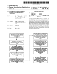
FIG. 4 is a ?owchart illustrating a main program of a digital
camera processor (DCP) illustrated in FIG. 3;
FIG. 5 is a ?owchart illustrating an embodiment of the
preview mode program of FIG. 4;
BACKGROUND OF THE INVENTION
FIG. 6 is a screen on which a preview image and setting
icons are displayed and overlap as a result of performing
This application claims the priority of Korean Patent
Application No. 10-2004-0094552, ?led on Nov. 18, 2004, in
the Korean Intellectual Property Of?ce, the disclosure of
which is incorporated herein in its entirety by reference.
operation S211 of FIG. 5;
FIG. 7 is a screen on which the setting icons are no longer
displayed as a result of performing operations S215 and
1. Field of the Invention
The present invention relates to a digital photographing
S216;
FIG. 8 is a ?owchart illustrating an embodiment of the
photographing mode program of FIG. 4;
apparatus and a method of controlling the same. More par
ticularly, the present invention relates to a digital photograph
FIG. 9 is a ?owchart illustrating an embodiment of the
ing apparatus that displays a preview image and overlaps the
preview image with setting icons indicating set operating
setting mode program of FIG. 4;
FIG. 10 is a screen on which folder icons and their sub
menus overlap a preview image and are displayed as a result
conditions of the digital photographing apparatus and a
method of controlling the digital photographing apparatus.
2. Description of the Related Art
20
A conventional digital photographing apparatus is dis
FIG. 11 is a screen showing the folder icons moved to the
left or right as a result of performing operation S606 of FIG.
closed in US. Patent Publication No. 2004/ 1 19,876 entitled
“Method of Noti?cation of Inadequate Picture Quality.” In
this disclosure, a preview image that is input through an
optical system and setting icons indicating set operating con
ditions of the digital photographing apparatus are displayed
of performing operation S603 of FIG. 9 according to an
embodiment of the present invention;
9; and
FIG. 12 is screen obtained as a result of terminating the
25
setting mode of FIG. 9 and performing the preview mode.
DETAILED DESCRIPTION OF THE PREFERRED
EMBODIMENTS
together, with the setting icons overlapping the preview
image.
When such a conventional digital photographing apparatus
display of the setting icons. Accordingly, for a quick photo
graphing operation, the user has to capture the preview image
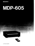
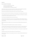
Referring to FIG. 1, the front part of a digital camera 1
according to an embodiment of the present invention includes
a self-timer lamp 11, a ?ash 12, a view?nder 1711, a ?ash
while it is made unclear by the setting icons since the user
luminance sensor 19, a lens unit 20, and a remote receiver 41.
is used, a user has to operate several buttons to terminate the
30
The top of the digital camera 1 includes a microphone MIC,
cannot quickly remove the setting icons from a screen.
35
SUMMARY OF THE INVENTION
In a self-timer mode, the self-timer lamp 11 operates for a
set period of time from the time when the shutter release
button 13 is pressed to the time when an image starts to be
captured. When the ?ash 12 operates, the ?ash-luminance
Various embodiment of the present invention provide a
digital photographing apparatus and a method of controlling
the same, wherein the apparatus and method minimize incon
40
venience in a photographing operation caused by displaying
setting icons that indicate operating conditions of the digital
photographing apparatus.
According to an embodiment of the present invention,
there is provided a digital photographing apparatus that (1)
displays a preview image and overlaps it with displayed set
ting icons indicating set operating conditions of the digital
45
sensor 19 senses luminance and relays the sensed luminance
to a digital camera processor (DCP) 507 of FIG. 3 via a
micro-controller 512 of FIG. 3. The remote receiver 41
receives command signals, for example, a photographing
command signal, from a remote controller (not shown) and
relays the photographing command signal to the DCP 507 via
the micro-controller 512.
The shutter release button 13 has two levels. In other
photographing apparatus, and (2) stops displaying the setting
words, referring to FIG. 8, when a user lightly depresses the
icons if a user does not generate a signal within a set period of
time.
a shutter release button 13, and a power switch 31.
50
shutter release button 13 to a ?rst level, a ?rst level signal SH1
from the shutter release button 13 is turned on. When the user
advance, thereby removing setting icons from a screen at
fully depresses the shutter release button 13 to a second level,
a second level signal SH2 from the shutter release button 13 is
appropriate timing without manipulating additional buttons.
turned on.
In the method, a user can adjust a set period of time in
Therefore, inconvenience in a photographing operation
caused by displaying the setting icons can be minimized.
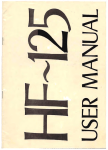
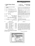
Referring to FIG. 2, the back of the digital camera 1 accord
BRIEF DESCRIPTION OF THE DRAWINGS
ing to an embodiment of the present invention includes a
mode dial 14, functional buttons 15, a manual focus/delete
button 36, a manual adjust/reproduce/terminate button 37, a
The above and other features and advantages of the present
invention will become more apparent by describing in detail
exemplary embodiments thereof with reference to the
attached drawings in which:
FIG. 1 is a perspective view illustrating the front and the top
reproduction mode button 42, a speaker SP, a monitor button
32, an automatic focusing lamp 33, a view?nder 17b, a ?ash
standby lamp 34, a color LCD panel 35, a wide-angle zoom
button 39W, a telephoto zoom button 391, and an external
interface unit 21.
The mode dial 14 is used for selecting the operating modes
55
60
of a digital camera according to an embodiment of the present
invention;
FIG. 2 is a perspective view illustrating the back of the
digital camera of FIG. 1;
of the digital camera 1. For example, a user may select modes
65
such as a simple photographing mode, a program photograph
ing mode, a character photographing mode, a night-view
photographing mode, a manual photographing mode, a mov
US 7,649,563 B2
4
3
The automatic focusing lamp 33 operates when automatic
ing-image photographing mode, a user-setting mode 14MY,
focusing is completed. The ?ash standby lamp 34 operates
and an audio recording mode 14V.
The user-setting mode 14MYis an operating mode in which
a user selects photograph-taking settings for each photo
when the ?ash 12 of FIG. 1 is in a standby mode. A mode
indicating lamp 14L indicates a selection mode of the mode
dial 14.
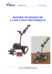
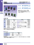
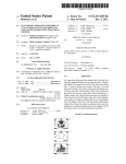
FIG. 3 is a schematic diagram of the con?guration of the
graphing mode. Reference numeral 14MP indicates the mov
ing-image photographing mode. The audio recording mode
14Vis for recording only sounds, for example, a user’s voice.
digital camera 1 of FIG. 1. The con?guration and operation of
the digital camera 1 of FIG. 1 will now be described with
After selecting the audio recording mode 14V, when a user
presses the shutter release button 13, an audio ?le is created in
the memory card and audio data is stored in the audio ?le.
When the user presses the shutter release button 13 again, the
audio data stops being stored and the audio ?le is set.
The functional buttons 15 are used for operating speci?c
functions of the digital camera 1. The functional buttons 15
reference to FIGS. 1 through 3.
An optical system (OPS) including the lens unit 20 and a
?lter unit optically processes light. The lens unit 20 of the
OPS includes a zoom lens, a focal lens, and a compensation
lens.
When the user presses the wide-angle zoom button 39 Wor
the telephoto zoom button 39Tincluded in a user input portion
(INP), a signal corresponding to the wide-angle zoom button
are also used as control buttons to manage the movement of an
active cursor on the menu screen of the color LCD panel 35.
39Wor the telephoto zoom button 39T is relayed to the micro
In a reproduction mode, if an image currently displayed is
controller 512. The micro-controller 512 controls a driver
not enlarged, when the user presses a self-timer/right button
15R, a next ?le in a forward direction is displayed. If an image
currently displayed is enlarged, when the user presses the
510, thereby running a zoom motor MZ, which, in turn, moves
20
lens becomes short, thereby widening the angle of view.
When the user presses the telephoto zoom button 39T, the
focus length of the zoom lens becomes long, thereby narrow
e.g., automatic photographing after 10 seconds, is performed.
In the reproduction mode, if the image currently displayed
25
the angle of view is hardly affected by the position of the
30
focus lens.
In the automatic focusing mode, a main controller built into
the DCP 507 controls the driver 510 through the micro
35
controller 512, thereby driving a focus motor MF. Accord
ingly, when the focus lens is moved, the position of the focus
lens, for example, a number of driving steps of the focus
motor MF, having a largest high frequency component of an
image signal is set.
currently displayed is enlarged, when the user presses the
?ash/left button 15L, the display area of the enlarged image is
?ash/left button 15L, any one of the ?ash modes for a photo
graphing mode is set.
In the reproduction mode, if the image currently displayed
is enlarged, when the user presses a macro/down button 15D,
the display area of the enlarged image is moved down. In the
preview mode, the user may set automatic proximity focusing
The compensation lens in the lens unit 20 of the OPS is not
separately operated because the compensation lens compen
by pressing a macro/ down button 15D.
sates for the entire refractive index. Reference numeral MA
In the reproduction mode, when the image currently dis
played is enlarged, if the user presses a voice-memo/up button
15 U, the display area of the enlarged image is moved up. In the
preview mode, if the user presses the voice-memo/up button
15U, a 10 second recording is possible upon consecutive
40
OPS eliminates high frequency optical noise. An infrared cut
component of incident light.
A photoelectric conversion unit (OEC) of a charge coupled
45
button 15 M when the active cursor is on a selection menu, the
operation corresponding to the selection menu is performed.
The manual adjust/reproduce/terminate button 37 is used
for manual adjustment of speci?c conditions. In the repro
duction mode, when the user presses the manual adjust/re
produce/terminate button 37, a selected moving-image ?le
may be reproduced or its reproduction may be terminated.
50
55
mode, when the user presses the monitor button 32, an image
and photographing information are displayed on the color
LCD panel 35. When the user presses the monitor button 32
again, the color LCD panel 35 is turned off. In the reproduc
sampler-and-analog-to-digital converter (CDS-ADC) 501.
The CDS-ADC 501 processes the analog signal from the
then converts the analog signal into a digital signal.
A real time clock (RTC) 503 provides time information to
the DCP 507. The DCP 507 processes the digital signal from
the CDS-ADC 501 and generates a digital image composed
of luminance and chromaticity values.
A light emitting portion (LAMP) is operated by the micro
controller 512 in response to a control signal generated by the
60
tion mode, when the user presses the monitor button 32 while
an image ?le is being reproduced, photographing information
about the image ?le is displayed on the color LCD panel 35.
When the user presses the monitor button 32 again, only
images are displayed.
The reproduction mode button 42 is used for switching
between the reproduction mode and the preview mode.
device or a complementary metal oxide (CMOS) semicon
ductor converts light from the OPS into an analog electrical
signal. Here, the DCP 507 controls a timing circuit 502 to
control the operations of the OEC and a correlation-double
OEC, eliminates high frequency noise, adjusts amplitude, and
The manual focus/delete button 36 is used for manual
focusing or deleting in the photographing mode.
The monitor button 32 is used for controlling the operation
of the color LCD panel 35. For example, in the photographing
indicates a motor for driving an aperture (not shown).
An optical low pass ?lter included in the ?lter unit of the
?lter included in the ?lter unit of the OPS blocks the infrared
photographing.
In a setting mode, if the user presses a menu/select-con?rm
ing the angle of view. Since the position of the focus lens is
adjusted in a state where the position of the zoom lens is set,
is not enlarged, when the user presses a ?ash/left button 15L,
a next ?le in a reverse direction is displayed. If the image
moved to the left. In the preview mode, if the user presses the
the zoom lens. In other words, when the user presses the
wide-angle zoom button 39W, the focus length of the zoom
self-timer/right button 15R, a display area of the enlarged
image is moved to the right. In a preview mode, if the user
presses the self-timer/right button 15R, a self-timer operation,
65
DCP 507 including the main controller. The light emitting
portion (LAMP) includes the self-timer lamp 11, the auto
matic focusing lamp 33, the mode indicating lamp 14L, and
the ?ash standby lamp 34. The user input portion INP
includes the shutter release button 13, the mode dial 14, the
functional buttons 15, the monitor button 32, the manual
focus/delete button 36, the manual adjust/reproduce/termi
nate button 37, the reproduction mode button 42, the wide
angle zoom button 39W, and the telephoto zoom button 39 T.
US 7,649,563 B2
5
6
A dynamic random-access memory (DRAM) 504 tempo
rarily stores a digital image signal from the DCP 507. An
electrically erasable and programmable read-only memory
example, 9 seconds, the DCP 507 terminates the setting mode
(S6) and performs a next operation (S8) because the user has
not generated a signal during the set period of time. In this
(EEPROM) 505 stores programs and setting data. A user’s
case, the folder icons and their sub-menus are no longer
memory card is inserted into or removed from a memory card
displayed. Thus, by adjusting the set period of time in
interface 506. The digital image signal from the DCP 507 is
advance, the user can remove the folder icons and their sub
menus from the screen at an appropriate time Without press
ing an additional button such as the menu/select-con?rm
input to an LCD driver 514, thereby displaying an image on
the color LCD panel 35.
The digital image signal from the DCP 507 can be trans
button 15M. Accordingly, inconvenience in the photograph
ing operation caused by displaying the folder icons and their
mitted as serial communications via a universal serial bus
(USB) connector 2111 or via an RS232C interface 508 and an
RS232C connector 21b. The digital image signal from the
sub-menus in the user-setting mode (S6) can be minimized.
An operation related to the setting mode Will be described in
DCP 507 can also be transmitted as a video signal via a video
detail later With reference to FIG. 9.
?lter 509 and a video output unit 210.
An audio processor 513 can relay sound from the micro
phone MIC to the DCP 507 or to the speaker SP. In addition,
the audio processor 513 can output an audio signal from the
DCP 507 to the speaker SP. The micro-controller 512 controls
the operation of a ?ash controller 511 in response to a signal
operation S6 is terminated, it can be understood that When the
user presses a setting button and thus generates a signal,
folder icons and their sub-menus corresponding to the setting
button are displayed.
When a termination signal is not generated, the DCP 507
from the ?ash-luminance sensor 19, thereby driving the ?ash
Considering that operation S5 can be performed after
20
When power is applied to the digital camera 1, the DCP 507
is initialized (S1). After the initialization (S1), the DCP 507
performs a previeW mode (S2). In the previeW mode, a pre
continues to perform the following operations (S7).
When a signal is generated by the reproduction mode but
12.
A main program of the DCP 507 of FIG. 3 Will be noW
described With reference to FIGS. 1 through 4.
ton 42 in the user input portion INP (S8), the timer that started
in the previeW mode (S2) or the setting mode (S6) stops (S8a)
25
vieW image input through the OPS and setting icons indicat
because the timer must be driven again in the previeW mode
(S2) or the setting mode (S6) if the user generated a signal. In
the reproduction mode, the DCP 507 performs a reproduction
operation in response to the signals received from the user
ing set operating conditions of the digital camera 1 are dis
input portion INP. When the reproduction mode is terminated,
played on the color LCD panel 35 (see FIG. 6).
Also, in the previeW mode (S2), the DCP 507 drives an
the above operations are repeated.
The previeW mode (S2) program Will noW be described
30
With reference to FIGS. 1 through 3 and FIG. 5.
internal timer if the internal timer is not on. If the operating
The DCP 507 performs automatic White balancing (AWB)
time of the internal timer exceeds a set period of time, for
example, 9 seconds, the setting icons are no longer displayed
and sets parameters related to the White balance (S201). The
DCP 507 performs automatic exposure (S202). The DCP 507
since the user did not generate a signal Within the set period of
time. Thus, by adjusting the set period of time in advance, the
35
calculates the exposure by measuring incident luminance,
icons on the display screen at appropriate timing Without
drives the aperture driving motor MA according to the calcu
lated exposure, and sets a shutter speed. Then, the DCP 507
pressing an additional button such as the monitor button 32.
performs automatic focusing (S203).
user can set the digital camera 1 to cease displaying the setting
Accordingly, inconvenience in a photographing operation
caused by displaying the setting icons can be minimized. An
operation related to the previeW mode Will be described in
40
detail later With reference to FIG. 5.
When the user lightly depresses the shutter release button
13 to the ?rst level and the ?rst level signal SH1 from the
shutter release button 13 is turned on (S3), the timer that
45
the input image data (S207).
started in the previeW mode (S2) or a setting mode (S6) stops
(S3a) because the timer must be driven again in the previeW
mode (S2) or the setting mode (S6) if the user generated a
signal. The DCP 507 performs a current photographing mode
(S4). The photographing mode (S4) program Will be
The DCP 507 performs gamma correction on input image
data (S204) and scales the gamma corrected image data to
meet display standards (S205). The DCP 507 converts the
scaled input image data from an RGB (red, green, and blue)
format into a luminance-chromaticity format (S206). The
DCP 507 processes the input image data depending on reso
lution and Where the input image data is displayed and ?lters
50
The DCP 507 temporarily stores the input image data in the
DRAM 504 of FIG. 3 (S208). The DCP 507 synthesizes the
data temporarily stored in the DRAM 504 of FIG. 3 and
on-screen display (OSD) data (S209). The OSD data denote
described in detail With reference to FIG. 8.
data of the setting icons indicating operating conditions of the
When a setting signal for setting operating conditions of
the digital camera 1 is generated by the user input portion INP
(S5), the timer that started in the previeW mode (S2) or the
setting mode (S6) stops (S5a) because the timer must be
driven again in the previeW mode (S2) or the setting mode
digital camera 1. The DCP 507 converts the synthesized
image data from the RGB format into the luminance-chroma
ticity format (S210) and outputs the image data in the con
55
FIG. 6).
The DCP 507 drives the internal timer if the internal timer
is not on (S212 and S213). If the internal timer is not driving
(S6) if the user generated a signal.
The setting mode for setting the operating conditions of the
and the digital camera 1 performs the previeW mode (S2) right
digital camera 1 is performed in response to signals received
from the user input portion INP (S6). In the setting mode,
folder icons and their sub-menus for setting operating condi
tions of the digital camera 1 overlap the previeW image and
60
If the operating time of the internal timer exceeds the set
11).
internal timer if the internal timer is not on. If the operating
time of the internal timer exceeds a set period of time, for
after being turned on, the timer is stopped in any one of
operations S311, S511 and S811 of FIG. 4 and operations S605a,
S607a and S609a of FIG. 9. Here, operations S212 and S213
may be performed just before operation S201.
are displayed on the color LCD panel 35 (see FIGS. 10 and
Also, in the setting mode (S6), the DCP 507 drives the
verted format via the LCD driver 514 of FIG. 3 (S211, see
65
period of time, for example, 9 seconds, the DCP 507 disables
the output of the OSD data and deletes the OSD data stored in
a frame memory (S214 through S216, see FIG. 7). When the
US 7,649,563 B2
7
8
user presses a particular button after the OSD data is deleted
Referring to FIGS. 10 through 12, reference numerals 35A
through 35C indicate display screens of the color LCD panel
35 of FIG. 1, reference numerals lC1 through 1C” indicate
folder icons for setting operating conditions of the digital
in operations S214 through S216, the DCP 507 can redisplay
the OSD data that has recently been deleted.
FIG. 6 is a screen on which a preview image and the setting
icons overlap and are displayed as a result of performing
camera 1, reference numeral 403 indicates folder names, lM
indicates speci?c items as sub-menus of each folder, and ISB
indicates an item selection bar. The setting mode (S6) pro
operation S211 of FIG. 5. FIG. 7 is a screen on which the
setting icons are no longer displayed as a result of performing
operations S215 and S216.
Referring to FIGS. 6 and 7, reference numeral 35 indicates
the color LCD panel and reference numeral IF indicates a
setting icon. If the operating time of the internal timer exceeds
a set period of time, for example, 9 seconds, the setting icons
gram of FIG. 4 will now be described with reference to FIGS.
1 through 3 and 9 through 12.
The DCP 507 controls the LCD driver 514 to display a
reference folder icon lC1 of FIG. 10 and its sub-menu of FIG.
10 on the color LCD panel 35 (S603, see FIG. 10). If OSD is
set for each reference folder icon, the OSD is enabled (S604).
If a left signal or a right signal is input from the user input
are no longer displayed since the user did not generate a signal
within the set period of time. Thus, by adjusting the set period
of time in advance, the user can remove the setting icons from
a screen at appropriate timing without pressing additional
button, for example, the monitor button 32. Accordingly,
inconvenience in a photographing operation caused by dis
playing the setting icons can be minimized.
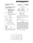
FIG. 8 is a ?owchart illustrating an embodiment of the
20
portion INP via the micro-controller 512 (S605), the DCP 507
terminates the operation of the internal timer if the internal
timer is driving (S605a) because the internal timer must be
driven again in the preview mode (S2) or the setting mode
(S6) if the user generated a signal. The DCP 507 moves all the
folder icons lC1 through 1C” to the left or right (S606). In this
photographing mode (S4) program of FIG. 4. The photo
process, the folder name 403 of an activated folder icon and
graphing mode (S4) program of FIG. 4 will now be described
with reference to FIGS. 1 through 3 and 8. Here, the current
position of the zoom lens is already set.
the speci?c items IM as the sub-menus of the activated folder
icon are displayed. In addition, the item selection bar ISB is
displayed on a recent setting item out of the displayed speci?c
The DCP 507 inspects the remaining capacity of the
25
memory card (S401) and determines whether the memory
card has enough capacity to store a digital image signal
(S402). If the memory card does not have enough storage
capacity, the DCP 507 indicates the lack of capacity of the
memory card and ends the photographing mode (S403). If the
memory card has enough storage capacity, the following
operations are performed.
If an up signal or a down signal is input from the user input
30
35
nance, drives the aperture driving motor MA according to the
calculated exposure, and sets exposure time (S406). In the
automatic focusing mode (S407), the DCP 507 performs
automatic focusing and drives the focal lens (S408).
When the ?rst level signal SH1 from the shutter release
button 13 is on (S409), the DCP 507 performs the following
portion INP via the micro-controller 512 (S607), the DCP 507
terminates the operation of the internal timer if the internal
timer is driving (S607a) because the internal timer must be
driven again in the preview mode (S2) or the setting mode
(S6) if the user generated a signal. The DCP 507 moves the
item selection bar ISB up or down (S608).
The DCP 507 sets white balance and parameters related to
the white balance according to a present photographing con
dition (S404). In the automatic exposure mode (S405), the
DCP 507 calculates the exposure by measuring incident lumi
items lM (see FIG. 11).
If a setting signal is input from the user input portion INP
via the micro-controller 512 (S609), the DCP 507 terminates
the operation of the internal timer if the internal timer is
driving (S609a) because the internal timer must be driven
again in the preview mode (S2) or the setting mode (S6) if the
40
user generated a signal. The DCP 507 updates recent setting
data as data that overlaps the item selection bar ISB (S610).
When the termination signal is generated by the user, the
DCP 507 terminates the setting mode (S611). Accordingly,
operations.
the folder icons lC1 through 1C” and their sub-menus are no
The DCP 507 identi?es whether the second level signal
SH2 is on (S410). When the second level signal SH2 is not on,
mination signal is not generated, the DCP 507 continues to
longer displayed (compare FIGS. 11 and 12). When the ter
45
it means that the user did not press the shutter release button
The DCP 507 drives the internal timer if the internal timer
is not on (S612 and S613). If the internal timer is not driving
13 to the second level to take a photograph. Then, the DCP
507 repeats S405 through S410.
When the second level signal SH2 is on, it means that the
user fully depressed the shutter release button 13 to the sec
ond level. Then, the DCP 507 creates an image ?le in the
memory card (S411). Next, the DCP 507 captures an image
(S412). In other words, the DCP 507 receives still-image data
from the CDS-ADC 501. Then, the DCP 507 compresses the
received still-image data (S413). The DCP 507 stores the
and the digital camera 1 performs the preview mode (S2) right
50
55
which folder icons lC1 through 1C” and their sub-menus
the folder icons lC1 through 1C” and their sub-menus are no
60
4).
longer displayed (compare FIGS. 11 and 12). Thus, by adjust
ing the set period of time in advance, the user can remove the
folder icons and their sub -menus from the screen at appropri
ate timing without pressing additional button, for example,
the menu/select-con?rm button 15M. Accordingly, inconve
result of performing operation S606 of FIG. 9. FIG. 12 is
(S6) of FIG. 9 and performing the preview mode (S2 of FIG.
507 repeats operation S605 and its subsequent operations.
Conversely, if the operating time of the internal timer
exceeds the set period of time, for example, 9 seconds, the
DCP 507 terminates the setting mode (S614). In other words,
FIG. 9 is a ?owchart illustrating an embodiment of the
setting mode (S6) program of FIG. 4. FIG. 10 is a screen on
screen obtained as a result of terminating the setting mode
after being turned on, the internal timer is stopped in any one
of operations S311, S511 and S811 of FIG. 4 and operations
S605a, S607a and S609a of FIG. 9.
If the operating time of the internal timer does not exceed
a set period of time, for example, 9 seconds (S614), the DCP
compressed still-image data in the image ?le (S414).
overlap a preview image and are displayed as a result of
performing operation S603 of FIG. 9 according to an embodi
ment of the present invention. FIG. 11 is a screen showing the
folder icons lC1 through lCn moved to the left or right as a
perform the following operations.
65
nience in the photographing operation caused by displaying
the folder icons and their sub-menus in the user-setting mode
(S6) can be minimized.
US 7,649,563 B2
10
When the user presses a particular button after the folder
8. The apparatus of claim 6, wherein the display positions
icons 1C1 through 1C” and their sub-menus are deleted from
the screen after the termination of the setting mode (S6), the
DCP 507 can redisplay the folder icons 1C1 through 1C” and
their sub-menus that have recently been deleted. In addition,
of the displayed members of the setting icons are shifted to the
left if the digital processor receives a left shift signal.
9. The apparatus of claim 1, wherein the setting icons are
for setting operating conditions of the apparatus.
the user may determine whether to use such an automatic icon
10. The apparatus of claim 1, wherein if less than all of the
plurality of icons are displayed at one time, a display position
hiding function.
As described above, according to a digital photographing
for each displayed member of the plurality of setting icons is
apparatus and a method of controlling the same, a user can
shifted in order to allow for displaying a currently un-dis
adjust a set period of time in advance, thereby removing
played member of the plurality of setting icons, and the shift
setting icons from a screen at appropriate timing without
ing of the icons terminates a timer associated with the set
manipulating additional buttons. Therefore, inconvenience in
period of time.
11. A method of controlling a digital photographing appa
ratus during a preview mode, the method comprising:
displaying both a preview image that is obtained through
a photographing operation caused by displaying the setting
icons can be minimized.
While the present invention has been particularly shown
and described with reference to exemplary embodiments
thereof, it will be understood by those of ordinary skill in the
art that various changes in form and details may be made
therein without departing from the spirit and scope of the
present invention as de?ned by the following claims.
an optical system and setting icons on a display screen;
determining how long the setting icons have been dis
played; and
20
ceasing to display all the setting icons while continuing to
display the preview image that is obtained through the
What is claimed is:
1. A digital photographing apparatus, the apparatus com
optical system if the signal is not detected within a set
prising:
an optical system having a lens unit that receives light from
a subject to be photographed by the apparatus;
25
while continuing to display the preview image that is
obtained through the optical system if the digital proces
sor does not receive the signal generated by the user
a digital processor for controlling what is displayed on the
30
12. The method of claim 11, wherein the setting icons are
image.
icons in a preview mode, and wherein the display screen
ceases to display all the setting icons while continuing to
13. The method of claim 11, wherein the set period of time
35
period of time;
mode in which the digital photographing apparatus
wherein OSD data stored in a frame memory is deleted
40
stores a ?le containing a photographed image; and
detecting a setting signal from the user input portion, and in
response thereto, entering a setting mode in which the
operating conditions of the digital photographing appa
sor does not receive the signal generated by the user
input portion within the set period of time.
2. The apparatus of claim 1, further comprising:
a photoelectric device that converts the received light to
is preset by a user.
14. The method of claim 11, further comprising:
detecting a photographing signal from the user input por
tion, and in response thereto, entering a photographing
optical system if the digital processor does not receive a
signal generated by the user input portion within a set
while continuing to display the preview image that is
obtained through the optical system if the digital proces
input portion within the set period of time.
displayed such that the setting icons overlap the preview
obtained through the optical system along with setting
display the preview image that is obtained through the
period of time;
wherein OSD data stored in a frame memory is deleted
a display screen;
a user input portion; and
display screen,
wherein the display screen displays a preview image that is
detecting whether a signal is inputted from a user input
portion or not; and
ratus may be set.
45
analog electrical signals;
15. The method of claim 14, wherein in the setting mode, a
folder icon for setting the operating conditions of the digital
an analog-to-digital conversion unit that receives the ana
photographing apparatus and its sub -menu are displayed such
log electrical signals and converts them to digital sig
nals, wherein the digital processor receives and pro
cesses the digital signals; and
that the folder icon and its sub-menu overlap the preview
50
a storage medium for storing a ?le containing a photo
graphed image.
setting mode.
55
4. The apparatus of claim 1, wherein the setting icons are
displayed overlapping the preview image.
60
each displayed member of the setting icons is shifted in order
to allow for displaying a currently undisplayed member of the
7. The apparatus of claim 6, wherein the display positions
right if the digital processor receives a right shift signal.
18. The method of claim 14, wherein the setting mode is
terminated if a second setting signal is not detected within the
set period of time.
19. The method of claim 11, wherein the setting icons are
for setting operating conditions of the apparatus.
20. A digital photographing apparatus, the apparatus com
setting icons.
of the displayed members of the setting icons are shifted to the
17. The method of claim 16, wherein when a setting button
is pressed by a user and a signal is generated after the termi
nation of the setting mode, the folder icon and its sub-menu
are displayed, wherein the sub-menu corresponds to the set
ting button.
5. The apparatus of claim 1, wherein the user input portion
comprises a button.
6. The apparatus of claim 1, wherein if less than all of the
setting icons are displayed at one time, a display position for
16. The method of claim 15, wherein the folder icon and its
sub -menu are no longer displayed after the termination of the
3. The apparatus of claim 1, wherein the set period of time
is preset by a user.
image.
65
prising:
means for receiving light from a subject to be photo
graphed by the apparatus;
US 7,649,563 B2
11
means for displaying both a preview image that is obtained
through the means for receiving light and setting icons in
a previeW mode;
12
obtained through the optical system if the digital proces
sor does not receive the signal generated by the user
input portion Within the set period of time.
means for detecting a user input;
21. The apparatus of claim 20, the apparatus further com
means for determining When a set period of time has 5 prising:
expired; and
means for ceasing the display of all the setting icons While
means for converting received light to digital signals;
means for processing the digital signals; and
means for storing an image ?le.
continuing to display the previeW image that is obtained
through the means for receiving light When the set period
22. The apparatus of claim 20, Wherein the setting icons are
of time has expired;
10 for setting operating conditions of the apparatus.
Wherein OSD data stored in a frame memory is deleted
While continuing to display the previeW image that is
*
*
*
*
*
UNITED STATES PATENT AND TRADEMARK OFFICE
CERTIFICATE OF CORRECTION
PATENT NO.
: 7,649,563 B2
Page 1 of1
APPLICATION NO. : 11/089740
DATED
INVENTOR(S)
: January 19,2010
: Seung-yun Lee
It is certified that error appears in the above-identified patent and that said Letters Patent is hereby corrected as shown below:
On the Title Page:
The ?rst or sole Notice should read -
Subject to any disclaimer, the term of this patent is extended or adjusted under 35 U.S.C. 15 4(b)
by 901 days.
Signed and Sealed this
Twenty-eighth Day of December, 2010
David J. Kappos
Director of the United States Patent and Trademark Oj?ce


![`95385109 1%]?](http://vs1.manualzilla.com/store/data/005699459_1-7fc02fda0f8970d7c2f678aea00486d8-150x150.png)