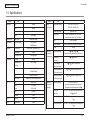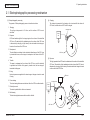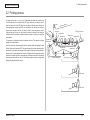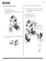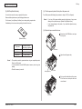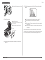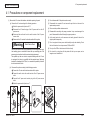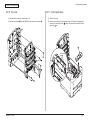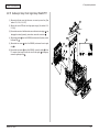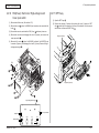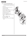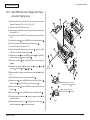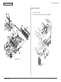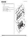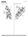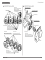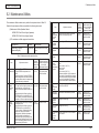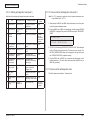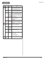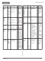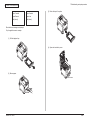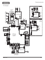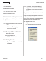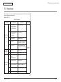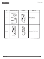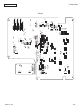
1
 C711 / MPS711c
Maintenance Manual
020712B
Copyright Information
Copyright © 2007 by Oki Data. All Rights Reserved
Disclaimer
Every effort has been made to ensure that the information in this document is complete, accurate, and up-todate. The manufacturer assumes no responsibility for the results of errors beyond its control. The
manufacturer also cannot guarantee that changes in software and equipment made by other manufacturers and
referred to in this guide will not affect the applicability of the information in it. Mention of software products
manufactured by other companies does not necessarily constitute endorsement by the manufacturer.
While all reasonable efforts have been made to make this document as accurate and helpful as possible, we
make no warranty of any kind, expressed or implied, as to the accuracy or completeness of the information
contained herein.
The most up-to-date drivers and manuals are available from the web site:
http://www.okiprintingsolutions.com
Oki Data CONFIDENTIAL
PREFACE
This manual provides an overview of method for maintaining the C711n.
This manual is intended for maintenance staff. For more information about how to operate
the C711n, please refer to User 's manual.
Note! • Manual may be revised and updated at any time without notice.
• Unexpected mistakes may exist in the manual.
OKI will not assume any responsibility whatsoever for damage to the
equipmentrepaired/adjusted/changed by the user etc with this manual.
• The par ts used for this printer may be damaged when handling
inappropriately. We strongly recommend maintaining this machine by our
registration maintenance staff.
• Please operate the machine after removing static electricity.
44205401TH Rev.1
/
Oki Data CONFIDENTIAL
Index
1. Configuration............................................................................ 6
3.6 Setting content print (Configuration).................................................................... 57
1.1 System configuration............................................................................................. 7
3.7 Connecting method............................................................................................. 58
1.2 The Configuration of printer................................................................................... 8
3.8 User used Paper confirmation............................................................................. 60
1.3 Optional parts........................................................................................................ 9
4.Component replacement....................................................... 61
1.4 Specifications...................................................................................................... 10
1.5 Specification of interface..................................................................................... 13
1.5.1 Specification of USB interface..................................................................... 13
1.5.1.1 General of USB interface...................................................................... 13
1.5.1.2 Connector and cable of USB interface.................................................. 13
1.5.1.3 USB interface signal............................................................................. 13
1.5.2 Specification of network interface................................................................ 14
1.5.2.1 General of network interface................................................................. 14
1.5.2.2 Connector and cable of network interface............................................ 14
1.5.2.3 Signal of network interface................................................................... 14
1.5.3 Specification of ACC interface..................................................................... 15
1.5.4 Specification of parallel interface................................................................. 16
1.5.4.1 General of parallel interface.................................................................. 16
1.5.4.2 Connector and cable of parallel interface............................................. 16
1.5.4.3 Parallel interface level........................................................................... 16
1.5.4.4 Signal of interface................................................................................. 16
2.Operating instructions........................................................... 17
2.1 Electrophotographic processing mechanism....................................................... 18
2.2 Printing process................................................................................................... 22
3.Set up......................................................................................33
3.1 Notes and precautions......................................................................................... 34
3.2 Unpack method................................................................................................... 35
3.3 Setting method.................................................................................................... 36
3.4 List of equipments and accessories.................................................................... 37
4.1 Precautions on component replacement............................................................. 62
4.2 Method of component replacement..................................................................... 64
4.2.1 Belt unit........................................................................................................ 64
4.2.2 Fuser unit..................................................................................................... 65
4.2.3 Left side cover.............................................................................................. 65
4.2.4 Right side cover........................................................................................... 66
4.2.5 Faceup tray ................................................................................................. 66
4.2.6 Rear cover................................................................................................... 67
4.2.7 LED Assy/ LED Assy spring........................................................................ 67
4.2.8 Control PCB................................................................................................. 68
4.2.9 Top cover Assy............................................................................................. 69
4.2.10 Top cover..................................................................................................... 70
4.2.11 Control panel Assy...................................................................................... 70
4.2.12 Board PRG/ LCD......................................................................................... 71
4.2.13 Frame panel Assy........................................................................................ 72
4.2.14 Low voltage power supply/Low voltage FAN/ Hopping motor/ Fuse motor.. 73
4.2.15 Guide eject Assy/ Color regist Assy/ Board-PRY........................................ 74
4.2.16 FAN(Fuser) / Belt motor/ High-voltage board/ Cover open switch............... 75
4.2.17 MPT Assy.................................................................................................... 75
4.2.18 Cover Assy front/ Board-RSF/MPT hopping roller/
Frame Assy separator/ Feeder Assy regist.................................................. 76
4.2.19 Board-PRZ/ Liftup motor/ Hopping motor//Paper end sensor/
Hopping sensor............................................................................................ 77
4.2.20 Feed roller................................................................................................... 78
4.2.21 Shaft eject Assy (FU)/ Shaft eject Assy(FD/ Eject sensor........................... 79
4.3 Oiling spots.......................................................................................................... 80
3.5 Assembling method............................................................................................. 38
3.5.1 Assemble the main body of the printer........................................................ 38
3.5.2 Cable connect.............................................................................................. 44
3.5.3 Optional part installation and confirmation................................................... 46
44205401TH Rev.1
5.Maintenance Menu................................................................. 91
5.1 System maintenance menu (for maintenance engineer) .................................... 92
/
Oki Data CONFIDENTIAL
5.2 Maintenance Utilities........................................................................................... 94
5.3 Maintenance menu functions............................................................................... 96
5.3.1 Self-diagnostic mode................................................................................... 96
5.3.1.1 Operation panel.................................................................................... 96
5.3.1.2 Ordinary self-diagnostic mode (level 1)................................................ 98
5.3.1.3 Switch scan test.................................................................................... 99
5.3.1.4 Motor clutch test................................................................................. 101
5.3.1.5 Test print............................................................................................. 103
5.3.1.6 Color registration correction test......................................................... 107
5.3.1.7 Density correction test........................................................................ 108
5.3.1.8 Consumable item counter display....................................................... 110
5.3.1.9 Number of print copies counter display.............................................. 111
5.3.1.10 Switching between the Factory mode and the Shipping mode........... 111
5.3.1.11 Self-diagnostic function setting........................................................... 112
5.3.1.12 LED head serial number display . ...................................................... 113
5.3.1.13 NVRAM parameter setting . ............................................................... 113
5.3.2 Various prints with the printer as a standalone unit................................... 113
5.3.3 Functions of keys at power on................................................................... 114
5.4 Setups upon completion of part replacement.................................................... 115
7.5.3 Troubleshooting the abnormal images....................................................... 182
7.5.4 Network troubleshooting............................................................................ 189
7.5.4.1 Connection error occurs with the Web browser.................................. 189
7.5.4.2 Print operation is not possible............................................................. 195
7.5.4.3 Cannot create Certificate.................................................................... 196
7.5.4.4 Installation of Certificate is not possible............................................. 196
7.5.4.5 Other questionnaires.......................................................................... 198
7.5.4.7 Network function restrictions on Sleep mode..................................... 201
7.6 Fuse check........................................................................................................ 202
7.7 Paper cassette switches versus Paper size correspondence table................... 203
8.Connection diagrams..........................................................204
8.1 Resistance value check..................................................................................... 205
8.2 Parts location..................................................................................................... 209
8.3 F/W version number.......................................................................................... 218
8.3.1 ROM control number.................................................................................... 218
8.3.2 ROM version check and display................................................................... 219
8.3.3 PCB Maintenance Indication Stamp............................................................. 219
5.4.1 Precautions when replacing the CU/PU board.......................................... 115
5.5 Density control manual setting.......................................................................... 117
5.6 Printer boot menu list......................................................................................... 118
6.Periodic Maintenance.......................................................... 120
6.1 Cleaning............................................................................................................ 121
6.2 How to clean the LED lens array....................................................................... 122
6.3 How to clean the pickup roller........................................................................... 124
6.4 How to clean inside of printer............................................................................ 125
7. Troubleshooting and repair procedure.............................. 127
7.1 Before starting the repair work.......................................................................... 128
7.2 Confirmation items before taking corrective action against abnormalities ....... 128
7.3 Precautions when taking corrective action against abnormality........................ 128
7.4 Preparation for troubleshooting......................................................................... 128
7.5 Troubleshooting method.................................................................................... 129
7.5.1 LCD message list....................................................................................... 129
7.5.2 Preparation for troubleshooting.................................................................. 150
44205401TH Rev.1
/
Oki Data CONFIDENTIAL
1. Configuration
1.1 System configuration......................................................................7
1.2 The Configuration of printer............................................................8
1.3 Optional parts.................................................................................9
1.4 Specifications...............................................................................10
1.5 Specification of interface..............................................................13
1.Configuration
Oki Data CONFIDENTIAL
1.1 System configuration
Figure 1-1 represents the system configuration of the printer.
LAN
Centronics
USB
Duplex
IN
FAN sensor
Acc
Duplex
clutch
(HOST USB)
2nd
hopping
sensor
2nd
IN
sensor
2nd
paper
size SW
DUPLEX PCB
2nd TRAY PCB
Hopping
clutch
Duplex
motor
K LED HEAD
Paper-feeding/
moving motor
CD1
ASIC (1/2)
Y LED HEAD
Front sensor PCB
M LED HEAD
Paper
size
SW
HOP
sensor
Option
RAM
C LED HEAD
Flash
ROM
EEP
ROM
Operation panel PCB
Environment
sensor
ID UP/
DOWN
K-ID
IN1
Paperfeeding
clutch
M-ID
RFID PCB
WR
M
IDUP
3rd
hopping
sensor
3rd
P.E
sensor
3rd
IN
sensor
3rd
paper
size SW
Feed
clutch
M
BELT
3rd TRAY PCB
CD1
ASIC (2/2)
EEPROM
Cover
open
sensor
M ID
IN2
Hopping
clutch
Belt unit
Paper-feeding/
moving motor
High-voltage I/F,
FAN control,
Cover open
FAN, heater control,
others
Belt unit
Fuse cut
Color blur, density,
thermistor signal
Fuse cut,
EXIT
Relay PCB
Fuser fuse cut/
Upper center/ For correction/
Lower thermistor
3.3V, 5V, 24V, 0VL, 0VP
Low-voltage PCB
High-voltage PCB
Y-ID
M
HOP
PU area
ID fuse cut
Belt
thermistor
Regist
clutch
Environmental
humidity
Toner sensor PCB
K Toner Y Toner M Toner C Toner
sensor sensor sensor sensor
MPT
clutch
Stacker
1st
full
P.E
sensor sensor
Option SD
Memory card
Fuser
FAN
2nd
P.E
sensor
Feed
clutch
Separator
solenoid
CU area
Cover Front Bottom
open sensor sensor
sensor
M
HEAT
C-ID
Low-voltage
FAN
Heater power
ID
cooling
FAN
Coler blur PCB
right
Color blur PCB
left
Density
sensor
EXIT
sensor
Fuser
Inlet
AC-SW
Fig1-1
44205401TH Rev.1
/
1.Configuration
Oki Data CONFIDENTIAL
1.2 The Configuration of printer
The parts in the C711n are shown as below.
• Electrophotography process mechanism
• Paper feed path
• Control part (CU part/ PU part)
• Operator panel
• Power part (High-voltage part/low-voltage part)
The Configuration of the printer is shown in Fig 1-2.
Air flow
Fig 1-2
44205401TH Rev.1
/
1. Configuration
Oki Data CONFIDENTIAL
1.3 Optional parts
The optional parts for this printer are shown as below.
(4) SD memory card
(1) Optional tray(second tray/ third tray)
(2) Duplex Unit
(3) Optional memory
44205401TH Rev.1
/
1. Configuration
Oki Data CONFIDENTIAL
1.4 Specifications
Division
Dimension
Item
Division
Width
435mm
Depth
536mm
Height
389mm
Weight
About 28kg
Width of print
Width of print
Print speed
Engine speed (A4)
Print start
First print time
8sec(mono), 9sec(color) (A4)
Warmup time
60sec
Low noise mode
Resolution
LED head
Maximum input
resolution
(120V)110~127VAC±10%,
(230V)220~240VAC±10%
Power save mode
Less than 15W
Sleep mode
Letter size, vertical
Idle
34PPM(Color)
36PPM(Mono)
Not applicable
Input power supply
Usual operation
Peak
Operating
environment
(Temperature)
600dpi
During operating
During nonoperating
About 0.9W (less than 1W) at AC120V
About 1W (less than 1.2W) at AC230V
100W (Average)
600W (It differs from operating environment)
1300W
10 ~32 , 17 ~27
(Temperature requirement for full-color print)
0 ~43 , power off
600×1200dpi
During keeping
(for a year at most )
-10 ~43 , with drum and toner
Output resolution
True 600×1200dpi
True 600×600dpi
During transferring
(for a month at most)
-29 ~50 , with drum, without toner
Step
4 step 600×600dpi
During transferring
(for a month at most)
-29 ~50 , with drum, without toner
Econo mode
CPU
Power
consumption
Item
Core
I-cash, /
D-cash
Clock
Save toner by recreasing brightness
PowerPC464
L1-I=32KB
L1-D=32KB
532MHz
Bus width
32bit
RAM
Resident
256MB
ROM
Program+font
64MB
44205401TH Rev.1
Operating
environment
(Humidity)
During operating
20%~80%, 50%~70%
(Humidity requirement for full-color print)
The highest wet bulb temperature is 25
During nonoperating
10%~90%, The highest wet bulb temperature is
26.8 , power off
During keeping
10%~90%, The highest wet bulb temperature is
35
During transferring
10%~90%, The highest wet bulb temperature is
40
10 /
1. Configuration
Oki Data CONFIDENTIAL
Division
Operation life
Item
Printer operation life
600,000 pieces A4 transvers direction, 5years
Print duty
(M=L/12, A=L/12/5)
Max 60,000 pages / month
Average 6,000 pages/ month
MTBF (2.3% duty)
Not applicable
MPBF
50,000 pages
MTTR
Within 20 minutes
Toner operation life
(ISO/IEC19798)
Transcribing belt
operation life
Fuser operation life
Operation
sound
During operation
During standby
Power save mode
Item
Paper handling
Paper stack capacity
(1st tray)
Legal /Universal cassette 530 pieces (70kg)
Paper stack capacity
(optional tray)
Legal /Universal cassette 530 pieces (70kg)
Paper stack capacity Standard multipurpose tray or 100 pieces (70kg),
(Manual/auto)
or 10 pieces of envelop
Paper rejection
Mounting toner: 4,000 pages(black), 4,000
pages(color)
Standard:
11,000 pages(black), 11,500 pages(color)
For the first new drum:
about 10,200 pages(black), 10,700 pages(color)
Image drum
operation life
Division
Duplex
Paper size
* : The paper of A6 cannot be used in tray 1, 2, 3
**: The post card, return post card and envelope
can be used in MPT only
***: As for custom, the available size can be
adjusted by using different tray. The length is
up to 1321mm.
60,000 pages (A4 transverse size, when 3 pages
/job) count auto reset
60,000 pages (A4 size) count auto reset
Minimum paper
size
Tray 1
Tray 2(option)
Tray 3(option)
MPT
A5
A5
A5
Postcard
Thickness of
paper
Tray 1
Tray 2(option)
Tray 3(option)
MPT
64g/m2~220g/m2
64g/m2~220g/m2
64g/m2~220g/m2
64g/m2~250g/m2
Control panel
LCD
37dB(ISO 7779 front)
Background level
LED (color)
Switch
44205401TH Rev.1
Standard/ Option
A4, A5, B5, A6*, letter, legal(13/13.5/14),
Executive, post card**, return post card**,
custom***, envelope , Index card 3x5in, Photo
size 4x6 5x7in
20,000 pages (when 3 pages /job)
12,000 pages (when 1 page/job)
27,000 pages (when continuously print)
Drum count all reset
54dBA (ISO 7779 front)
(without option unit)
350 pieces (70kg), facedown/
100 pieces (70kg), faceup tray
Resolution 128×64 dot graphic panel
Paper size is not displayed
2 (Green×1, dark umbar×1)
8
11 /
1. Configuration
Oki Data CONFIDENTIAL
Division
Status switch/
sensor
Communication
interface
Item
Paper out
Have
Paper low
None
Toner low
Have (Y, M, C, K)
Cover open
Have
Temperature of fuser
Have
Paper size
Have (Manual setting)
Stacker full
Have
Standard
(On the PCB)
Input and output
switch
Emulation
Division
Standard
• Hi-Speed USB
• Ethernet
• Centronics
Auto
Option
(can be
removed)
Item
RAM
SD memory card
It is possible to be
installed by user
Tray mechanism
Cassette
Double print unit
Others
Others
256/512MB DIMM
16GB or 32GB SD memory card
2nd tray mechanism, 3rd tray mechanism
Universal (530 pieces)
Standard/ Option
Not available
USB-IF logo
Have
Windows logo
Have
UPS operation
The operation with UPS(Uninterruptible Power
Supplies) is not guaranteed.
Please do not use the UPS.
PCL(PCL5c, HP-GL) /
PCL XL3.0
PostScript3 (Clone)
XPS
Font
Emulation switch
Auto
Bitmap Typeface
Have
Scalable font
Have
Rasterizer
Have
Barcode
Have
OCR
Have
Japanese PCL font
Have
Japanese PS font
Have
44205401TH Rev.1
12 /
1. Configuration
Oki Data CONFIDENTIAL
1.5 Specification of interface
1.5.1 Specification of USB interface
(2) Cable
1.5.1.1 General of USB interface
(Less than 2m is recommended)
(Please use the shielded wire for the cable.)
The length of the cable: the cable of less than 5m with USB 2.0 spec.
(1) Spec.
USB (Support Hi speed USB )
1.5.1.3 USB interface signal
(2) Transmission mode
Full speed (Maximum 12Mbps 0.25%)
High speed(Maximum 480Mbps 0.05%)
(3) Power control
Self power device
1.5.1.2 Connector and cable of USB interface
(1) Connector
• Printer side: Signal name
Function
1
Vbus
Power (+5V)
2
D-
For data transmission
3
D+
For data transmission
4
GND
Shell
Shield
Signal Ground
B Receptacle (female)
Up-stream port
(UBR24-4K5C00 (made by ACON)) Equivalent goods
Connector pins array
2
1
3
4
• Cable side: B plug(male)
44205401TH Rev.1
13 /
1. Configuration
Oki Data CONFIDENTIAL
1.5.2 Specification of network interface
1.5.2.1 General of network interface
1.5.2.2 Connector and cable of network interface
(1) Connector
100BASE-TX/10 BASE-T (Auto switch, cannot be used simultaneously)
Spec.
Connector pins array
Network Protocol
1
TCP/IP sepc. Network layer
Transfer layer
8
ARP, IP, ICMP, IPv6, IPSec
TCP, UDP
Application layer
LPR, Port9100, FTP, HTTP, HTTPS, IPP, SNMPv1/v3, TELENET,
DHCP/BOOTP, DNS, DDNS, WINS, UPmP, Bonjour, SNTP,
SMTP, POP, Windows Rally (WSD Print, LLTD).
NBT/NetBEUI: SMB, NetBIOS, NetBIOS over TCP
Netware: Remote printer mode(Maximum 8 print sever )
Print sever mode (Maximum 8 files sever: 32 queue)
For encrypted password (when it is print sever mode)
NetWare6J/5J/4.1J (NDS, bindery)
SNMP
EtherTalk:
ELAP, AARP, DDP, AEP, NBP, ZIP, RTMP, ATP, PAP
IEEE802.1X: EAP-TLS, PEAP
44205401TH Rev.1
(2) Cable
Non-shield twisted-pair cable with RJ-45 connector
(Category 5 is recommended)
1.5.2.3 Signal of network interface
Pin No.
Signal name
Direction
Function
1
TXD+
FROM PRINTER
Transmission data +
2
TXD-
FROM PRINTER
Transmission data -
3
RXD+
TO PRINTER
Receive data +
4
−
−
Not use
5
−
−
Not use
6
RXD-
TO PRINTER
Receive data -
7
−
−
Not use
8
−
−
Not use
14 /
1. Configuration
Oki Data CONFIDENTIAL
1.5.3 Specification of ACC interface
1) Connector
Printer side:
Cable side:
5) Connecting device
ODC-authorized card reader/writer
Maximum current supplied to the printer: 100 mA
USB A receptacle (female)
Downstream port
DUSB-ARA42-T11A (DDK product) or equivalent
USB A plug (male)
2) Cable
Hi-Speed USB2.0
Cable length: 2.0 m max.
(Use a shielded cable.)
Note! A cable doesn’t come with the printer.
3) Interface signals
Contact No.
1
2
3
4
Shell
Signal Name
VBUS
DD+
GND
Shield
Function
Power supply(+5V)
For data transfer
For data transfer
Signal ground Shell
Shield
4) Conector pin arrengement
44205401TH Rev.1
15 /
1. Configuration
Oki Data CONFIDENTIAL
1.5.4 Specification of parallel interface
Pin NO.
1.5.4.1 General of parallel interface
1
Spec.
1.5.4.4 Signal of interface
Name of signal
Content
Related mode
Compatible mode, nibble mode, and ECP mode
Data bit length
Compatible: 8, nibble: 4, ECP: 9bit
1.5.4.2 Connector and cable of parallel interface
2~9
DATA 1~DATA 8
Bi-direction
It is parallel data of 8 bits. The high level is
“1", and the Low level is “0".
10
nAck(PtrClk)
FROM
PRINTER
It is a signal that shows the data reception
completion.
11
Busy(PtrBusy)
FROM
PRINTER
It is a signal that shows if the printer is
receiving the data. Data cannot be received
when it is at the high level.
12
PError
(AckDataReq)
FROM
PRINTER
The paper error is shown when it is at the
high level.
13
Select(Xflag)
FROM
PRINTER
When parallel interface is effective, it is
always in high-level state.
(1) Connector
14
Printer side : 36-Pole connector (Female)
Function
nStrobe (HostClk) TO PRINTER It is a pulse to read data. Data is read by
posterior end.
IEEE1284-1994 conforming parallel interface
Item
Direction
nAutoFd(HostBusy) TO PRINTER It is used by the bidirectional communication.
57LE-40360-12(D56) (made by DDK) equivalent goods
15
-
-
Not use
16
GND
-
Signal ground
17
FG
-
Chassis ground
18
+5V
FROM
PRINTER
19~30
GND
-
31
nInit(nInit)
32
nFault(nDataAvail)
FROM
PRINTER
33
GND
-
Signal ground
34
-
-
Not use
35
HILEVEL
FROM
PRINTER
Cable side : 36-Pole connector (male)
57FE-30360-20N(D8) (made by DDK) equivalent goods
18
36
1
19
Pin layout seen from interface cable side
(2) Cable
IEEE1284-1994 cable of less than 1.8m is used.
(For avoiding noise interference, please use shielded cable with the twisted-pair wire.)
36
1.5.4.3 Parallel interface level
Low level
0.0V~+0.8V
High level
+2.4V~+5.0V
44205401TH Rev.1
It cannot supply power outside.
Signal ground
TO PRINTER The printer is initialized with the low level.
When the printer is in alarm state, it
becomes low level.
It is pulled up to +5V at 3.3K in the printer.
nSelectIn
TO PRINTER It is used by bidirectional communication. It
(IEEE1284 active)
must be low level when it is in compatible
mode.
Notes! • The signal name showed in the bracket is a signal name in nibble mode.
• It only describes the function in compatible mode.
• The nibble mode of IEEEstd1284-1994 regulated by Institute of Electrical
and Electronics Engineers is supported. Using the computer and the
cable unsupported this standard may lead to unexpected operation.
16 /
Oki Data CONFIDENTIAL
2. Operating instructions
2.1 Electrophotographic processing mechanism................................18
2.2 Printing process............................................................................22
2. Operating instructions
Oki Data CONFIDENTIAL
2.1 Electrophotographic processing mechanism
(1) Electrophotographic processing
(2) Charging
The general of Electrophotography process is described as below.
The voltage is impressed to the charging roller in contact with the surface of
OPC drum, and the surface of OPC drum is charged.
1. Charging
The voltage is impressed to CH roller, and the surface of OPC drum is
electrified.
Charging roller
Power
unit
2. Exposure
--
LED head irradiates light to the image signal on the surface of the electrified
OPC drum. The electricity of the irradiated part on the surface of the OPC drum
is attenuated by changing in light intensity, the electrostatic latent image is
formed on the surface of the OPC drum.
- - -
3. Development
The electrified toner adheres to the electrostatic latent image of the OPC drum
by electrostatic force, and the image is developed on the surface of the OPC
drum.
4. Transfer
The paper is overlapped on the surface of the OPC drum, and the electricity
is generated on the back of the paper by transfer roller, the toner image is
transcribed to the paper.
OPC drum
(3) Exposure
The light generated from LED head is irradiated onto the surface of the electrified
OPC drum. The electricity of the irradiated part on the surface of the OPC drum is
attenuated by changing in light intensity, the electrostatic latent image is formed
on the surface of the OPC drum.
5.Fusing
Heat and pressure are applied to the toner image on the paper in order to make
it fusing.
LED head
6. Drum cleaning
The drum cleaning blade removes the toner left on the OPC drum after transfer.
7. Electricity removal
Charging roller
Power
unit
The electric potential left on the drum is removed.
--
LED head
- - -
-
--
8. Belt cleaning
The belt cleaning blade removes the toner left on the belt.
OPC drum
Paper
44205401TH Rev.1
OPC drum
18 /
2. Operating instructions
Oki Data CONFIDENTIAL
(4) Development
(5) Transfer
The toner adheres to the electrostatic latent image on the surface of the drum,
and the electrostatic latent image is changed into the toner image.
The paper is overlapped on the surface of the OPC drum, and the electricity is
generated on the back of the paper by transfer roller.
1. The sponge roller makes the toner adhere to the developing roller.
When high voltage is impressed from the power supply to the transfer roller, the
electricity induced in the transfer roller is moved to the surface of the paper via
contact surface, and the toner is drawn from the surface of the OPC drum to the
surface of the paper.
Charging roller
--
- - -
-
--
--
Sponge roller
-
- - -
-
--
OPC drum
Developing roller
-
OPC drum
-
2. The electrostatic latent image on the surface of the OPC drum surface is
visualized by toner.
Paper
-+ -+ -+ -+ -+ -+ -+ -+ -+ -+ -+ -+
-+
-+
-+
-+
-+
Transport belt
Transfer roller
Power
unit
44205401TH Rev.1
19 /
2. Operating instructions
Oki Data CONFIDENTIAL
(6) Fusing
(7) Drum cleaning
When the paper passes through the heat roller and backup roller unit, heat and
pressure are applied to the toner image on the paper and the toner is fused onto
the paper.
The halogen lamps of 800W and 400W are built in heat roller. The backup roller
without built-in halogen lamp is heated by the heat transmission from the heat
roller. The fusing temperature is controlled by the temperature detected by the
thermistor that is not in contacting with the surface of the heat roller. On the
other hand, the temperature detected by the thermistor rubbing the surface
of backup roller is used for controlling the fusing temperature under specified
conditions. Furthermore, a thermostat is used to limit the temperature rise, if
the temperature rise of heat roller exceeds a set point, the thermostat would be
open and the voltage supply to the heater would be cut off. The backup roller
unit is pressed on the heat roller by the spring on both sides.
The Unfused toner left on the OPC drum is cleaned up by the drum cleaning
blade, and all residual toner is collected in the waste toner area of the toner
cartridge.
Waste toner area
Toner cartridge
Thermostat
ID unit
Thermistor
-
Drum cleaning blade
Paper feeding path
-
Heat roller
Paper
-+ -+ -+ -+ -+ -+ -+ -+ -+ -+
-+
-+
Backup roller
(8) Electricity removal
Pad
The electricity on the surface of the OPC drum is attenuated by irradiating the
light to the surface of the OPC drum after transfer.
Electricity-removing
light PCB
Fuser belt
Charging roller
Thermistor
Electricity-removing
light
OPC drum
44205401TH Rev.1
20 /
2. Operating instructions
Oki Data CONFIDENTIAL
(9) Belt cleaning
The toner left on the transport belt is cleaned up by the belt cleaning blade, and
all residual toner is collected in the waste toner box of the transport belt unit.
Transport belt
Belt waste toner box
Belt cleaning blade
44205401TH Rev.1
21 /
2. Operating instructions
Oki Data CONFIDENTIAL
2.2 Printing process
The paper fed from tray 1 or tray 2, tray.3 is transferred by feeder roller, resister roller
L, and transfer roller. It is transferred by MPT paper feed roller and resister roller U
when the paper is fed from MPT. After that, the paper on the belt passes through the
electrophotography process of KYMC, and sequentially the unfused toner image is
generated on the paper. And then, the toner is fused by heat and pressure when it
is passed through the fuse unit. After fusing, the paper is delivered to the faceup or
facedown stacker by utilization of different delivery methods by opening or closing the
faceup stacker.
The operation of single-sided printing is described as above. The operation of duplex
printing is described as below.
As for the duplex print, the paper passed the fuse unit after initially back printing is drawn
into the Duplex unit by separator DUP. The paper entered into the paper reversing path is
transferred from the paper reversing path to the inside of Duplex by reverse operation of
reversal roller. The paper passed over the inside of Duplex is fed from paper feed path of
Duplex by the transfer roller set in the transfer path of Duplex inside, which is shared with
the same paper feed path from the tray. The following operation is same as single-sided
printing with paper feeding from the tray.
r
n stacke
w
Face-do
Heat roller
Fac
e
-up
sta
cke
r
MPT paper feed roller
Halogen lamp
Backup roller
Transport belt
Resister roller U
Separator DUP
Reversal roller
MPT
Transport roller
Paper reversing path
Resister roller L
Paper feed roller
Transport roller
Transport roller
44205401TH Rev.1
22 /
2. Operating instructions
Oki Data CONFIDENTIAL
(2) Paper feeding from MPT
(1) Paper feeding from 1st tray
1. As figure 2-1 shows, a feed motor runs clockwise, a feed clutch engages and
paper is fed (a feed roller rotates when the feed clutch engages).
2. After turning on an IN1 sensor, the paper is fed further a determined length
until it touches a registration sensor L (this corrects skews of the paper).
3. As figure 2-2 shows, a registration clutch engages and the registration roller
L feeds paper (the registration roller L rotates when the registration clutch
engages).
WR Sensor
IN2 Sensor
Registration Clutch
(not engaging)
Registration Roller U
(rotating)
Registration Roller L
(not rotating)
1. As figure 2-3 shows, a feed motor runs counterclockwise, an MPT clutch
engages and paper is fed (an MPT feed roller rotates when the MPT clutch
engages).
2. After turning on an IN2 sensor, the paper is fed further a determined length
until it touches a registration roller U (this corrects skews of the paper).
3. As figure 2-4 shows, the feed motor runs clockwise and the registration roller
U feeds the paper (the registration roller U rotates when the feed motor runs
clockwise).
MPT Feed Roller
(rotating)
WR Sensor
Registration Roller U
(not rotating)
MPT Clutch
(engaging)
IN2 Sensor
IN1 Sensor
Feed Clutch
(engaging)
Feed Roller
(rotating)
Feed Motor
(running clockwise)
Feed Motor
(running counterclockwise)
Paper
Figure 2-1
Figure 2-3
Registration Clutch
(engaging)
MPT Feed Roller
(not rotating)
Registration Roller L
(rotating)
MPT Clutch
(not engaging)
Registration Roller U
(rotating)
Feed Clutch
(not engaging)
Feed Roller
(not rotating)
Feed Motor
(running clockwise)
Feed Motor
(running clockwise)
Paper
Figure 2-2
44205401TH Rev.1
Figure 2-4
23 /
2. Operating instructions
Oki Data CONFIDENTIAL
(3) Transport belt
1. When the transport belt motor is rotated in the direction of the arrow, the
transport belt is driven. As for the belt unit, a transfer roller is set over under
each color drum. The belt is caught and installed between the transfer roller
and drum.
As for the transport belt and transfer roller, if the specified voltage is
impressed, the paper on the transport belt would be delivered to the fuser
unit while transcribing the toner image on each color drum.
Drum
Transport belt
K
Y
M
C
Transfer roller
Transport belt motor
Figure 2-5
44205401TH Rev.1
24 /
2. Operating instructions
Oki Data CONFIDENTIAL
(4) Updown operation of ID unit
1. The up and down operation of the ID unit is done by driving the liftup motor.
2. Fig. 2-6 shows the operation of each ID unit when color printing. When the
liftup motor is rotated (counter clockwise), the liftup link slides to left, and
each ID unit is in DOWN condition as shown in Fig. 2-6. Under this condition,
the color printing is available.
The operation of each ID unit when color printing
C-ID unit DOWN
M-ID unit DOWN
Y-ID unit DOWN
K-ID unit DOWN
C-ID unit
M-ID unit
Y-ID unit
K-ID unit
Y-ID unit
K-ID unit
3. Fig. 2-7 shows the operation of each ID unit when mono printing. When the
liftup motor is rotated (clockwise), the liftup link slides to right, and each ID
unit (except K-ID unit) is in UP condition as shown in Fig. 2-7. Under this
condition, the mono printing is available.
Liftup link
Liftup motor (CCW)
Figure 2-6
The operation of each ID unit when mono printing
C-ID unit Liftup
M-ID unit Liftup
Y-ID unit Liftup
K-ID unit DOWN
C-ID unit
M-ID unit
Liftup link
Liftup motor (CW)
Figure 2-7
44205401TH Rev.1
25 /
2. Operating instructions
Oki Data CONFIDENTIAL
(6) Cover open operation of color blur sensor and density sensor
(5) Fuse unit and paper delivery
1. The fuse unit and the delivery roller are driven by the DC motor as shown in
Fig. 2-8. When the fuse motor is rotated (counter clockwise), the heat roller
will begin to rotate. The heat roller makes the toner image fused to the paper
by heat and pressure.
2. The paper exits while the delivery roller rotates.
1. As shown in Fig. 2-9, when the fuse motor is rotated (clockwise), the cover
open gear is operated and the cover of color blur sensor and density sensor
is open.
2. When the fuse motor is rotated (counter clockwise) in the opposite direction,
the cover open gear is moved out of engagement and the cover of color blur
sensor and the density sensor is close.
Eject roller
(Stop)
Eject roller
(Drive)
Fuser unit
Heat roller
(stop)
Heat roller
(Drive)
Fuse motor
(CW)
Fuse motor
(CCW)
Cover open gear
Figure 2-8
44205401TH Rev.1
Figure 2-9
26 /
2. Operating instructions
Oki Data CONFIDENTIAL
General of color blur correction
The color blur correction is operated by reading the pattern for correction printed on the
belt with a sensor set in the sensor shutter under the belt unit.
Transport belt
The pattern is detected by this sensor, and the correction is operated.
Color blur correction auto-start timing
• When the power is on
• When the cover is closed after the cover is opened once
• When more than 400 copies are printed or when more than 6 hours have elapsed
since the last print
• The Sleep mode has no color blur correction auto-start timings.
Belt waste toner box
Sensor shutter
The amount of toner of the pattern, the toner left on the sensor and the open-close
trouble of the shutter etc. may lead to correction error. However, as the error message
may not display even if the error is occurred, it is necessary to perform the color blur
correction (see 5.3.2.6) by the utilization of the self-diagnostic mode and confirm the error
display.
Color blur sensor
Belt cleaning blade
Color blur sensor
Right color blur correction pattern
Left color blur correction pattern
Color blur sensor
44205401TH Rev.1
27 /
Oki Data CONFIDENTIAL
2. Operating instructions
Error-confirming method and Error-solving method
Use the color blur correction test function in self-diagnostic mode to confirm the
error. (See 5.3.1.6)
Error solving method
•CALIBRATION(L or R), DYNAMICRANGE(L or R)
Check 1: W hen the above display appears, please check the connection
of sensor cable (FFC).
When the connection is abnormal, please set it properly.
Check 2: Please check if the surface of the sensor is dirty with the toner and paper
melts etc.
Check 3:Please confirm if the open and close operation of sensor shutter is
normal by utilization of MOTOR&CLUTCH TEST in self-diagnostic mode.
Exchange the shutter unit when the open and close operation is in
trouble.
If there are no problems in check 1, 2, and 3, please check the circuit.
Please exchange the color adjust sensor PCB, relay PCB, PU PCB, and the cable
one by one, and then check if the error is displayed.
•BELT REFLX ERR
Check 4: When this display appears, please check the cleaning of the toner left
on the surface of the belt after finishing the above-mentioned check 1, 2,
and 3. Remove the belt unit, and rotate the left inboard drive gear. Please
confirm that the surface of the belt is cleaned completely.
When the residual toner left on the surface of the belt could not be
cleaned completely even if the drive gear is rotated, please exchange the
belt unit.
•(Y or M or C) LEFT, (Y or M or C) RIGHT, (Y or M or C) HORIZONTAL
Check 5: When the above display appears, please confirm if the toner of NG color
is empty.
Please exchange the toner cartridge as required.
44205401TH Rev.1
28 /
2. Operating instructions
Oki Data CONFIDENTIAL
General of the density correction
The density correction is operated by reading the pattern for correction printed on the belt
with a sensor set in the sensor shutter under the belt unit.
Transfer belt
Density correction auto-start timing
• The environment is remarkably different from last time when the power is on.
• When one or more ID count among the four ID count show the status of new part,
at the power on
• The ID count value exceeds 500-count from last operation.
• When one or more UD is replaced with the new ID.
• When the belt is replaced with the new belt
• When toner cartridge is replace due to Toner Low, or Toner Empty so that Toner
Low or Toner Empty has disappeared
Belt recycling toner box
Sensor shutter
Density sensor
Belt cleaning blade
Density sensor
The amount of toner of the pattern, the toner dirt and the open-close trouble of the shutter
etc. may lead to correction error.
However, as the error message may not display even if the error is occurred, it is
necessary to perform the density correction (see 5.3.1.7) by the utilization of the selfdiagnostic mode and confirm the error display.
Density correction pattern
44205401TH Rev.1
29 /
2. Operating instructions
Oki Data CONFIDENTIAL
Error-confirming method and Error-solving method
Toner sensor detection principle
Use the density correction test function in self-diagnostic mode to confirm the error.
Toner low is detected by the toner sensor (reflect sensor) installed in the equipment.
The light board is installed in ID, and its rotation is synchronized with the mixing of toner.
Moreover, the shutter is installed in ID. Toner cartridge set properly by the lever of toner
cartridge and synchronized toner sensor can be detected.
(See 5.3.1.7)
Error solving method
• CALIBRATION ERR, DENS SENSOR ERR
Check 1:When the above display appears, please check the connection of sensor
cable.
When the connection is abnormal, please set it properly.
Check 2:Please check if the surface of the sensor is dirty with the toner and paper
melts etc.
Please wipe the dirt off if the sensor is dirty.
The following problems may lead to abnormal detection and the toner sensor error is
occurred.
If there are no problems in check 1, 2, and 3, please check the circuit.
Shutter
Please exchange the density sensor, relay PCB, PU PCB, and the cable one by one,
and then check if the error is displayed.
Toner sensor
Light board
•DENS SHUTTER ERR
Check 3:Please confirm if the open and close operation of sensor shutter is
normal by utilization of MOTOR&CLUTCH TEST in self-diagnostic mode.
Exchange the shutter unit when the open and close operation is in
trouble.
•DENS ID ERR
Check 4:Remove the ID unit, and confirm if the toner abnormally leaves on the
surface of the drum.
Exchange LED head (Focus control). Or exchange the ID unit.
When a new ID unit is tried to use, please set the fuse keep mode of the
maintenance menu.
Toner count principle
After the image data is transformed into binary data which can be printed by the printer, the
data is counted as print dot number by LSI. The amount of the used toner is calculated from this
count value, and the residual amount is displayed on the menu.
Toner LOW detection (residual amount display on LCD) by the toner sensor is to detect a
certain amount of the reduction of the toner left in ID.
The principle of ID counter, belt counter, fuse counter
ID counter :
when 3 pieces of A4 paper are continuously printed, one third of the
rotation of the drum is set as one count.
Belt counter : when 3 pieces of A4 paper are continuously printed, one thirdof the
rotation of the drum is assumed as one count.
Fuse counter :The length of paper of legal 13 inch is set as nominal value.
If the length of paper is less than this nominal value, it is assumed as
one count. If the length of paper is more than this nominal value,the
counted number is determined by the times of legal 13 inch.
(The number after decimal point is rounded up.)
44205401TH Rev.1
30 /
2. Operating instructions
Oki Data CONFIDENTIAL
Counter spec
Total printed page
number
MPT printed page
number
Tray 1 printed page
number
Tray 2 printed page
number
Tray 3 printed page
number
Color-printed page number
Mono-printed page number
Description
Total printed page
number
Hopping page
number from MPT
Hopping page
number from Tray1
Hopping page
number from Tray2
Hopping page
number from Tray3
Printed page number by
color-printing
Printed page number by
mono-printing
Count method A4
conversion or size
independence
Count up after
passing the writing
sensor
Count up if
MPF(MPT) hopping
is finished
Count up if Tray1
hopping is finished
Count up if Tray2
hopping is finished
Count up if Tray3
hopping is finished
The page number is counted
up by detecting the paper
passing the fuser in colorprinting mode after the job is
finished. (1*)
The value is A4/Letter value.
Please refer to A4/ Letter
conversion table (P31).
The page number is
counted up by detecting the
paper passing the fuser in
mono-printing mode after
the job is finished. (1*)
The value is A4/Letter
value.
Please refer to A4/ Letter
conversion table (P31).
Operation when
paper jammed
Cannot count when paper feeding (hopping) jam and feed jam are occurred.
It can count except the above-mentioned jam.
As total printed page number is counted up when the front end of the page passes the writing sensor, according to
the jam type, the feeding jam (380) is also included in the limits for counted.
Cannot count if the jam is occurred before the paper passes
the fuser.
It can count if the jam is occurred after the paper passes the
fuser.
Operation for
Duplex
Front/Back count(+2)
Only front count (+1)
Double count
If the color page and mono page exist together, the color
printing page number would be plus 1 and the mono printing
page number would be plus 1.
Reset condition
None
None
1) When "Format Flash ROM" of system maintenance menu
is performed.
2) When CU PCB is replaced.
3) When MENU RESET of system maintenance menu is
performed.
4) When CU PCB is replaced.
Value storage
destination
Menu/MenuMap
output
EngineMenuMap
output
PU
PU
PU
PU
PU
CU
CU
−
−
(*2)
(*3)
(*3)
(*3)
(*3)
*1. Count cannot be updated if the power is turned off when the jam is occurred.
*2. In the initial state MenuMap output is not available. It is possible to switch in the system maintenance menu.
*3. EngineMenuMap output divides into Engine Menu Print (the first page) and Engine EEPROM Dump Print (the last page), however, the number of paper fed from each tray is
output only to the latter one (DUMP display only).
44205401TH Rev.1
31 /
2. Operating instructions
Oki Data CONFIDENTIAL
A4/Letter conversion table
The paper is counted up as this sheet.
Paper size
Simplex
Duplex
LETTER
1
2
EXECUTIVE
1
2
LEGAL14
1
2
LEGAL13.5
1
2
LEGAL13
1
2
A4
1
2
A5
1
2
A6
1
-
B5
1
2
COM-9
1
-
COM-10
1
-
MONARCH
1
-
DL
1
-
C5
1
-
CUSTOM LENGTH ≤ 210mm
1
2
CUSTOM 210mm < LENGTH ≤ 899mm
2
4
CUSTOM 900mm ≤ LENGTH
4
-
44205401TH Rev.1
32 /
Oki Data CONFIDENTIAL
3. Set up
3.1 Notes and precautions..................................................................34
3.2 Unpack method............................................................................35
3.3 Setting method.............................................................................36
3.4 List of equipments and accessories.............................................37
3.5 Assembling method......................................................................38
3.6 Setting content print (Configuration).............................................57
3.7 Connecting method......................................................................58
3.8 User used Paper confirmation......................................................60
3. Set up
Oki Data CONFIDENTIAL
3.1 Notes and precautions
• Do not set it in any high-temperature locations or near any heat sources.
• Do not set it in a place where the chemical reaction may occur (laboratory etc.).
• Do not set it near any liquid that may ignite such as alcohol and thinner.
• Do not keep it out of reach of children.
• Do not place it on an unstable or uneven surface
(unstable table and slanting place, etc.).
• Do not put it in direct sunshine. And do not put it in a moist or dusty place.
• If the liquid such as water enters the printer, please pull out the power plug from the
outlet and contact the customer center.It may cause fire.
• If you drop the foreign objects such as clip in the printer, please pull out the power
plug from the outlet and take the foreign objects out.
This may cause an electric shock, fire, injury.
• Do not disassemble the printer unless following the correct procedure written in the
manual.This may cause an electric shock, fire, injury.
• Do not set it in wet or corrosive environment.
• Do not set it in a place where may cause vibration.
• If the printer is dropped down or the cover is damaged, please pull out the power
plug from the outlet and contact the customer center.
This may cause an electric shock, fire, injury.
• Do not set it in a place where the vent hole of the printer is blocked.
• Do not set it directly on heavy wool or shag carpet.
• Please read this manual carefully before connecting the power supply cable, printer
cable, ground cable.
This may cause fire.
• Do not place it in locations of poor ventilation such as enclosed areas.
• Do not insert any foreign objects into the vent hole.
This may cause an electric shock, fire, injury.
• Do not place it close to strong magnetic fields and noise source.
• Do not put a vessel(s) filled with water on the printer.
This may cause an electric shock, fire.
• Hold tightly the both sides of the printer when you move the printer.
• Do not touch the fuser unit when you open the cover of the printer.
It is hot and could cause burns.
• Do not throw the toner cartridge, the image drum cartridge into the fire.
It may cause burns due to dust explosion.
• Do not use inflammable sprays near the printer.
It may cause fire because some parts in the printer may become very hot.
• If the cover becomes abnormally hot, smoke rises, it smells strange or it sounds
abnormal, please pull out the power plug from the outlet and contact the customer
center.
It may cause fire.
44205401TH Rev.1
• Give particular attention to adequate ventilation care when using it continuously in a
narrow room for a long time.
• Do not place it next to the monitor and television.
• Because the weight of the printer is approximately 33kg (in a state of packing), it
needs more than two adults to lift it up.
• Do not come close to the paper exit part while printing.
This may cause injury.
Please explain the safety precautions about installation and handling with showing the
all precautions in user's manual to customer. Especially, the details about power supply
cable and the ground cable must be explained completely.
34 /
3. Set up
Oki Data CONFIDENTIAL
3.2 Unpack method
Personal injuries may occur.
Because the weight of the printer (without Duplex unit) is
approximately 33kg (in a state of packing), it needs more than
two adults to lift it up.
• Take out the gripe on each side as shown in the following figure, and lift the
cardboard box up.
Gripe
(Four gripes on all sides)
44205401TH Rev.1
35 /
3. Set up
Oki Data CONFIDENTIAL
3.3 Setting method
• Set the printer under these conditions.
Surrounding environment:
10~32
Surrounding humidity:
20~80%RH (Relative humidity)
Plan view
20cm
Highest wet bulb temperature: 25
• Protect the printer from dew formation.
• Use the humidifier or the static electricity prevention mats etc. when setting the
printer in the environment where the humidity is 30% or less.
Set space
100cm
60cm
• The flat desk should be wide enough to put the printer on.
• Ensure that there is enough room around the printer for proper ventilation.
20cm
Side view
70cm
44205401TH Rev.1
36 /
3. Set up
Oki Data CONFIDENTIAL
3.4 List of equipments and accessories
• Make sure that the appearance of the equipment is not damaged or dirty etc.
Printer software CD-ROM
• Make sure that the following accessories are supplied with your printer.
Power supply cord
• If you are missing any of these accessories, contact your customer service
department immediately.
Guarantee card and user registration card
Personal injuries may occur.
Because the weight of the printer body is approximately 28kg
(33kg in a state of packing), it needs more than two adults to lift it up.
User’s manual (Setup)
User’s manual (CD-ROM)
Notes! The printer cable is not included.
Printer (Body)
Image drum cartridge (1 Cyan, 1 the magenta, 1 yellow, and 1 black) (mounted in
the printer)
Explain to the customer that the toner cartridge and the image drum cartridge can
be separated.
44205401TH Rev.1
37 /
3. Set up
Oki Data CONFIDENTIAL
3.5 Assembling method
3.5.1 Assemble the main body of the printer
(3) Peel off the protection tape (4 places) on the back of the printer.
Remove the protective materials.
(1) Peel off the desiccant and the protection tape (four places) on the printer.
Desiccant
Duplex unit
Protection tape
Protection tape
(4) Confirm that the Duplex unit is fixed tightly.
Protection tape
(5) Pull the paper cassette out.
(2) Peel off the paper on the front of printer.
Paper
44205401TH Rev.1
38 /
3. Set up
Oki Data CONFIDENTIAL
(6) Pull the retainer out in the direction of the arrow (1). Return the paper cassette
to the main body of the printer.
(8) Remove the stopper (orange) when pressing down the lever of the fuser unit
(blue) in the direction of arrow .
Note! If you do not use the printer for a long time or transport it, please use the
stopper. Please keep it carefully.
Lever of fuser unit (Blue)
Retainer
Stopper (Orange)
(7) Press down the OPEN button, and open the top cover.
OPEN button
44205401TH Rev.1
39 /
3. Set up
Oki Data CONFIDENTIAL
Set the image drum cartridge.
(2) Put the image drum cartridge on the newspaper etc, peel off the tape of
protection sheet 1 and pull it out in the direction of the arrow.
(1) Take the image drum cartridge (four) out slowly.
Note! • The image drum (green cylinder) is very fragile. Please pay special
attention to handling it.
• Do not expose the image drum cartridge to direct sunshine and strong
light (about 1500 lux). And do not expose it to room light for more than 5
minutes.
Tape
Protection sheet 1
Protection sheet 1
Protection sheet 2
Starter toner cartridge
Image drum
cartridge
(3) Pull the protection sheet 2 out from image drum cartridge in the direction of
arrow.
Protection sheet 2
(4) Remove all protection sheets from the image drum cartridge.
44205401TH Rev.1
40 /
3. Set up
Oki Data CONFIDENTIAL
(5) Return the image drum cartridge back to the printer.
(7) Close the top cover.
Note! If the message of [%COLOR% Waste Toner Full.Replace Toner.] on the
control panel doesn't disappear indefinitely, please make sure that the lever
of the toner cartridge is fully moved in the direction of the arrow.
(6) Turn the lever of each starter toner cartridge in the direction of the arrow.
(Four levers)
Lever(Blue)
44205401TH Rev.1
41 /
3. Set up
Oki Data CONFIDENTIAL
Set the paper into the paper cassette.
(4) Place the paper in the cassette with the side to be printed facing down.
(1) Pull out the paper cassette.
Do not peel off the rubber attached to the plate.
(2) Adjust the paper stopper and the paper guide to match the size of the paper,
and then fix them tightly.
Note! • Place the paper with the top of the page nearest the paper cassette tab.
• Do not place the paper higher than the " " mark on the paper guide. (530
pieces for 70kg paper)
(5) Place the paper in position by paper guide.
(6) Rotate the paper size dial to match the paper.
(7) Return the paper cassette back to the printer.
Paper guide
Paper stopper
Place the printed side
facing down.
Plate
mark
(3) Flex the paper back and forth. Do not fold or crease the paper. Straighten the
edges on a level surface.
Paper guide
Paper size dial
Paper set direction
44205401TH Rev.1
42 /
3. Set up
Oki Data CONFIDENTIAL
Set the paper in multi-paper tray.
(4) Place the printed side facing up, and insert the paper along the manual insertion
guide straightly until bumping up.
(1) Open the multi-paper tray, and open the paper supporter.
Multi-paper tray
(2) Match the manual insertion guide to the size of the paper.
(3) Flex the paper back and forth. Straighten the edges on a level surface.
Note! Set papers so that paper should not exceed the " " mark. (100 sheets of
paper with ream weight of 70 kg or 10 envelopes)
(5) Press down the set button.
Manual insertion guide
Multi-paper tray
Paper supporter
Manual insertion
guide
Set button
44205401TH Rev.1
43 /
3. Set up
Oki Data CONFIDENTIAL
3.5.2Cable connect
Power condition
• Keep the following items.
AC voltage
: 110~127V ± 10%/ 220~240V ± 10%
Frequency of the power supply : 50Hz or 60Hz ± 2%
•Use the voltage adjusting transformer etc. when the power supply is unstable.
•The maximum power consumption of this printer is 1,300W. Confirm the power
supply can provide enough power.
•The operation with UPS (uninterruptible power supplies) is not guaranteed.
Explain to the customers that do not use UPS (uninterruptible power supplies).
It may cause an electric shock, fire.
• Installation and removal of the power supply cord and the ground cable must be performed after pressing
down the power switch to OFF.
• Please connect the ground cable with a specified ground terminal. Please contact the dealer if you cannot get it.
• Be careful not to connect it with the lightning rod, the water pipe, the gas pipe, and the earth of the
telephone wire.
• Connection of the ground terminal must be performed before inserting the power plug into the power outlet.
And, removal of the ground terminal must be performed after pulling the power plug out of the power outlet.
• Please hold the power plug to disconnect or plug in the power supply cord.
• Please insert the power plug firmly into the outlet.
• Do not pull out or plug in the power plug with wet hands.
• Do not locate the printer in a place where the cord may be abused by persons walking on, and do not place
the heavy objects on the power cord.
• Do not use the power supply cord that is bundled or connect the power supply with an extension cord.
• Do not use a damaged power supply cord.
• Do not use a multiple outlet extension cord.
• Please connect this printer into an outlet different from that to which other electric products is connected.
Especially, the operation of the printer might be affected by the electrical noise when the printer is connected
simultaneously with the air-conditioner, the copier and shredder etc. Please use the noise filter or the noise
cut-off transformer sold at the market if you have to connect the printer into a same outlet.
• Please use the attached power cord and insert it into the outlet directly. Do not use an unspecified power cord.
• Do not use an extension cable. Please use a cable that is more than 15A current rating if you have to use
an extension cable.
•If the extension cord is used, the printer might operate abnormally by the decrease of AC voltage.
•Do not unplug the power cord or switch off the power during printing.
•Please unplug the power cord if you do not use the printer for a long time (long vacation or travel etc).
•Do not use the attached power cord of this printer to the other electric products.
Explain completely the connection of the power supply cable and the ground cable with
showing the user's manual to customer.
44205401TH Rev.1
Connect the power cord.
Note! Confirm that the power switch is turned to OFF "
(1) Insert the power cord into the printer.
O
".
I
(2) Connect the ground cable with the ground terminal of the outlet.
Ground terminal
Ground cable
It may cause an electric shock.
The ground cable must be connected.
(3) Insert the power plug into the outlet.
Press down the power switch to ON( | ).
O
I
If the printer is completely started up, the message "Ready To Print" would be displayed
on the control panel shown as follows.
Note! When the printer is getting cold, it may lead to error if the power is turned
on. (Error number 126,171,175,177,320). At this time, please turn off the
power and wait for a while, and then turn on the power again.
44 /
3. Set up
Oki Data CONFIDENTIAL
Turn the power off.
When you do not use the printer for long time
Note! If you turn off the power without properly shutting down, it may cause
damage to the printer. Please follow the following procedure to turn the
power off.
Please explain to the customer about the following items.
Unplug the power cord if you do not use the printer for a long time (long vacation or travel etc).
Install the stopper to the fuser.
(1) A message [Shut down Yes/No] appears. Be sure Yes is selected and press the
Set
[Back] button.
A message [Shutting down] appears, the printer being shutting down.
Note!Please remove the ground terminal after pulling the power plug out
of the power outlet.
[Back] button
Note!Even if the power plug of this printer is pulled out for a long time (four
weeks or more), the functional problems will not be caused easily.
However, please explain to the customer that the deterioration of
consumable such as toners and the image drums is not guaranteed.
(2) If the message [Turn off power/Shutdown completed] is displayed, press down
the power switch to OFF " ".
O
44205401TH Rev.1
I
45 /
3. Set up
Oki Data CONFIDENTIAL
3.5.3Optional part installation and confirmation
(1) Installation of the optional tray unit (second/ third tray)
(1)-2. Install the optional tray unit to the printer.
Note! Because the weight of the printer body is approximately 28kg, it needs
more than two adults to lift it up.
It is a traditional paper tray for adding paper into printer.
Match the tab into the hole in the bottom of the printer.
530 pieces of 70kg paper can be set. Using it with a standard paper cassette and a multipurpose tray can print 1690 pieces of pages continuously.
Put the printer on the optional tray unit slowly.Please remove it following the
steps 1-2 in reverse order.
Hole in the bottom of the printer
Tab
(1)-1. Turn the printer power to OFF and pull out the power cord from the outlet.
Turn the power off with following the procedure in chapter 3.5.2 [Turn the power
off.].
Notes! • If you turn off the power without properly shutting down, it may cause
damage to the printer. Please operate the [Shutdown Menu].
• It may cause damage to the printer, if you install the optional tray with
power ON.
Note! When you install two optional trays to the printer, set the optional tray
directly on top of the other optional tray, and then put them on the printer.
Hole in the bottom of the printer
Hole in the bottom
Tab
Tab
44205401TH Rev.1
46 /
3. Set up
Oki Data CONFIDENTIAL
(1)-3. Connect the power cord and printer cable to the printer and turn the
power on.
Note! If the message [Service Call/182: Fatal Error] or [Service Call/183: Fatal
Error] is displayed, reinstall the optional tray unit.
(1)-4. Print the setting content and confirm if the option tray unit is installed
properly.
Print the setting content with following the procedure in chapter 3.6.
(1)-5. Set the number of tray by the printer driver.
The printer driver setup for recognizing the option tray unit is required.
If the printer driver is not set up, please set up the printer driver completely referring to
the user's manual (Setup) firstly, and then finish the following setting procedure.
Note! The authority of the computer administrator is required.
For windows PS printer driver
For Windows Vista, click on [start] =>
[control panel] => [printer].
Confirm the content of [tray 2] or [tray 3] is display in header part.
For Windows XP, click on [start] =>
[control panel] => [printer and other
hardware] => [printers and Faxes].
For WindowsServer 2003, click on
[start] => [printers and faxes].
For Windows 2000, click on [start] =>
[Settings] => [printers].
Click the [C711(PS)] icon with rightNote! If the content of [tray 2] or [tray 3] is not displayed, reinstall the second tray
unit.
(For Windows XP)
c l i ck bu t t o n o n yo u r m o u s e a n d
choose the [Properties].
Choose [get information from printer]
from [installable options] in [Device
options] tab, and click [setup] or [get
information from printer]. For USB
connection, set [Optional paper
source] manually.
Click [OK].
44205401TH Rev.1
47 /
3. Set up
Oki Data CONFIDENTIAL
For Mac OS X
For Windows PCL printer driver
For Windows Vista, click on [start] =>
[control panel] => [printer].
For Windows XP, click on [start] =>
[control panel] => [printer and other
hardware] => [printers and Faxes].
For WindowsServer 2003, click on
[start] => [printers and faxes].
If the printer is connected by [AppleTalk], the device information could also not be
gotten automatically when the optional device has been added into in Mac OS X
before installing the printer driver.
For Windows 2000, click on [start] =>
[Settings] => [printers].
Please finish the following setting procedure for above.
Click [C711(**)] (** is PCL or PCL
XPS (printer driver type)) icon with
right-click button on your mouse and
choose [Properties].
(For Windows XP)
Choose [get information from printer]
in [Device options] tab. For USB
connection, input the optional tray
number in [Optional devices] manually.
Click [OK].
44205401TH Rev.1
When the optional device has been added into in Mac OS X before installing the
printer driver, the device information is gotten automatically. However, if the printer is
connected by [IP print] and [Bonjour (Rendezvous)], the device information could not
be gotten automatically.
Double-click [Applications] for hard
disk => [utility] => [print setting utility]
([Applications] => [Utility] => [print
center] in Mac OS X)
Select [C711], click [Show info] and
open [printer info].
Choose [installable options].
Select the [Optional paper source],
and click [Apply].
Close [printer info].
48 /
3. Set up
Oki Data CONFIDENTIAL
(2) Installation of Duplex unit
(2)-3. Install Duplex Unit
This unit is used for printing on two sides of paper.
Note! For two-sides printing, it is recommended to add expansion memory. For
details, see "Expansion memories."
Insert the Duplex unit into the lower part on the back of the printer as far as
it will go.
Ensure that the claw on either side of the Duplex unit is securely
accommodated in the hole of the printer.
Holes
Claws
(2)-1. Turning OFF the printer power and disconnecting the power cord
Note! If an expansion memory is installed with the power switched ON, the printer
may be broken.
O
I
Duplex unit
(2)-2. Peeling the protective tapes off the Duplex unit
Protective tapes (2)
44205401TH Rev.1
49 /
3. Set up
Oki Data CONFIDENTIAL
(3) Add the optional memory.
(3)-1. Turn the power of printer off, and pull out the power cord.
It is used to increase the memory capacity of the printer.
Turn off the power with following the procedure in chapter 3.5.2 [Turn off power].
Please add the optional memory as following problems occur:
“Out of memory” error [Memory Overflow] occurs when printing complex data.
Combination print error occurs when printing the whole file at once.
Notes! • If you turn off the power without properly shutting down, it may cause
damage to the optional memory. Operate the [Shutdown Menu].
• It may cause damage to the printer, if you install the optional memory
with power ON.
(3)-2. Open the top cover and front cover.
Press down the OPEN button, and open
the top cover.
Optional memory
Type name
Memory capacity
(Total memory capacity)
None (Standard)
256MB (256MB)
MEM256G
+256MB (512MB)
MEM512D
+512MB (768MB)
OPEN button
Open the multi-purpose tray.
Notes! • The operation cannot be guaranteed when using an unspecified product.
Please use OKI product.
• It is recommended to add 256MB optional memory when long size
printing.
• The slot for memory is one slot.
Multi-purpose tray
Handle
Pull up on the handle (blue) at the center
of the front cover, and open the front
cover forward.
Front cover
44205401TH Rev.1
50 /
3. Set up
Oki Data CONFIDENTIAL
(3)-3. Remove the side cover.
(3)-4. Install the memory.
Loose the screw (one place).
Remove the side cover.
Pull it outward to remove while holding the
upper edge of the side cover to lift.
Discharge any static electricity by
touching a grounded metal object
before taking the memory out of the
package.
Insert the memory into the slot.
Screw
Side cover
Push the memory to the printer side
and fix it firmly.
Notes! • Do not touch any electrical parts and terminals of connectors.
• Be careful to install the memory in the proper direction. A notch on the
terminal of the memory is matched to the connector of the slot.
44205401TH Rev.1
51 /
3. Set up
Oki Data CONFIDENTIAL
(4) Install the SD memory card.
(3)-5. Install the side cover.
Install the side cover.
Fix the side cover with the screw. (one
place)
Note! Be careful that the font cannot be downloaded.
Close the top cover and front cover.
Top cover
Screw
Side cover
(4)-1.Turn the power of printer off, and pull out the power cord.
Front cover
(3)-6. Connect the power cord and printer cable to the printer, and turn the
power on.
Please turn off the power with following the procedure in chapter 3.5.2 [Turn off
power].
Notes! • If you turn off the power without properly shutting down, it may cause
damage to the printer. Please operate the [Shutdown Menu].
• It may cause damage to the printer, if you install the optional memory
with power ON.
Note! If the message [Service Call/031:Fatal Error] is displayed, please reinstall
the memory.
(3)-7. Print the setting content and confirm if the optional memory is installed
properly.
Print the setting content with following the procedure in chapter 3.6.
Confirm the total memory capacity displayed in [Total Memory] of [System]
part.
Note! If total memory capacity displayed in [Total Memory] is incorrect,
please reinstall the memory.
44205401TH Rev.1
52 /
3. Set up
Oki Data CONFIDENTIAL
(4)-2. Open the top cover and front cover.
(4)-3. Remove the side cover.
Loose the screw (one place).
Remove the side cover.
Press down the OPEN button, and open
the top cover.
OPEN button
Pull it outward to remove while holding
the upper edge of the side cover to lift.
Screw
Side cover
Open the multi-purpose tray.
(4)-4. Install the built-in SD Memory Card.
Multi-purpose tray
Handle
Observing the orientation of the SD
Pull up on the handle (blue) at the center
of the front cover, and open the front
cover forward.
memory card, insert it into the slot on
the printer side.
Note! The card cannot be used with
its write-protect switch (to guard
against accidental erasure on the
card) in the unlocked position. To
use the card, be sure to place the
switch in the locked position.
Front cover
44205401TH Rev.1
53 /
3. Set up
Oki Data CONFIDENTIAL
Press the SD memory card until it clicks.
(4)-5. Install the side cover.
Install the side cover.
F i x t h e s i d e c ove r w i t h t h e s c r ew.
(one place)
Close the top cover and front cover.
(4)-7. Print the setting content and confirm if the SD memory card is installed
properly.
Print the setting content with following the procedure in chapter 3.6.
Confirm the SD Memory Card capacity displayed in [SD Card].
MemoThe capacity of SD memory card might be different from the example of
the above figure.
Note! Please reinstall the SD memory card when the capacity of SD Card is
not displayed.
Top cover
Screw
Side cover
And, the printer driver setup for recognizing the SD memory card disk is required.
If the printer driver is not set up, please set up the printer driver completely referring to
the user's manual (Setup) firstly, and then finish the following setting procedure.
Front cover
(4)-6. Connect the power cord and printer cable to the printer, and turn the
power on.
44205401TH Rev.1
54 /
3. Set up
Oki Data CONFIDENTIAL
(4)-8. Set [SD memory card] by printer driver
For Windows PCL printer driver
For Windows Vista, click on [start]
Note! The authority of the computer administrator is required.
=> [control panel] => [printer].
For windows PS printer driver
For Windows XP, click on [start]
=> [control panel] => [printer and
other hardware] => [printers and
Faxes].
For Windows Vista, click on [start]
=> [control panel] => [printer].
For Windows XP, click on [start]
=> [control panel] => [printer and
other hardware] => [printers and
Faxes].
For WindowsServer 2003, click on
[start] => [printers and faxes].
For Windows 2000, click on [start]
=> [Settings] => [printers].
For Windows Server 2003, click
on [start] => [printers and faxes].
Click [C711(PCL)]icon with rightclick button on your mouse and
choose [Properties].
For Windows 2000, click on [start]
=> [Settings] => [printers].
Choose [get infor mation from
Click the [C711(PS)] icon with
(For Windows XP)
right-click button on your mouse
and choose the [Properties].
Choose [get infor mation from
printer] from [installable options]
in [Device options] tab, and click
[setup] or [get information from
printer]. For USB connection, set
[SD Memor y card] as [Install]
manually.
(For Windows XP)
printer] in [Device options] tab. For
USB connection, select the option
[SD Memory card] manually.
Click [OK].
Click [OK].
44205401TH Rev.1
55 /
3. Set up
Oki Data CONFIDENTIAL
For Mac OS X
When the optional device has been added into in Mac OS X before installing the
printer driver, the device information is gotten automatically. However, if the printer is
connected by [IP print] and [Bonjour (Rendezvous)], the device information could not
be gotten automatically.
If the printer is connected by [AppleTalk], the device information could also not be
gotten automatically when the optional device has been added into in Mac OS X
before installing the printer driver.
Please finish the following setting procedure for above.
Double-click [Applications] for
hard disk => [utility] => [print
setting utility] ([Applications] =>
[Utility] => [print center] in Mac
OS X)
Select [C711], click [Show info]
and open [printer info].
Choose [installable options].
Select the [SD Memor y Card]
option, and click [Apply].
Close [printer info].
C o n f i r m t h e a d d e d p r i n t e r i s
shown in [Printer list], and close
[print center].
44205401TH Rev.1
56 /
3. Set up
Oki Data CONFIDENTIAL
3.6 Setting content print (Configuration)
To confirm the printer operates normally, please print the [Configuration].
(C711n sample)
(1) Set A4 paper in tray.
(2) Press the
button for several times so that [Print Information] is displayed,
and press down the
(3) Press the
(4) Press down the
button.
button and select [Configuration], press down the setting button.
button.
The setting content print is started.
MemoWhen printing the network setting infor mation (2 pieces Network
Information), press the
button after (2), and press down the
button after [Network] is displayed.
A Demo page or a file list can be printed in the same way as Network does.
44205401TH Rev.1
57 /
3. Set up
Oki Data CONFIDENTIAL
3.7 Connecting method
<USB connection>
Note! Please refer to user’s manual for operation environment.
Prepare for USB cable
Notes!• The printer cable is not included.
Provide the USB2.0 cable for special user.
• When connecting the cable in [Hi-Speed] mode of USB 2.0, please use
the USB cable with Hi-Speed spec.
• Select the USB cable of less than 5m. It is recommended to use the
USB cable of less than 2m.
Connect the computer to the printer.
(1) Insert the USB cable into the USB interface connector of printer.
(2) Insert the USB cable into the USB interface connector of computer.
Note! Do not insert the USB cable into the network interface connector.
It may cause trouble.
Turn the printer and computer OFF.
MemoAlthough USB cable can plug-and-play with computer and printer power
on, after this the setup of printer driver and USB driver may be required.
Here the printer is turned off to plug-and-play the USB cable.
USB Interface connector
MemoPlease refer to user’s manual for setup of printer driver.
44205401TH Rev.1
58 /
3. Set up
Oki Data CONFIDENTIAL
< Ethernet cable connection>
< Parallel connection>
Note! Refer to user’s manual for operation environment.
Prepare for Parallel cable
Note! The parallel cable is not included in printer. Provide it for special user.
Prepare for Ethernet cable
Note! The Ethernet cable and Hub is not included in printer.
Provide the Ethernet cable and Hub for special user.
<Ethernet cabl>
<Hub>
Turn the printer and computer OFF.
O
I
Turn the printer and computer OFF.
Connect the computer to the printer.
(1) Insert the Ethernet cable into the network interface connector of printer.
(2) Insert the Ethernet cable into Hub.
MemoRefer to user’s manual for setup of printer driver.
Connect the computer to the printer.
(1) Insert the parallel cable into the parallel interface connector of printer, and Lock
it firmly by metal fittings.
(2) Insert the parallel cable into the parallel interface connector of computer, and fix
it firmly with screws.
Metal fittings
Screw
Network interface
connector
Screw
Parallel cable
44205401TH Rev.1
59 /
3. Set up
Oki Data CONFIDENTIAL
3.8 User used Paper confirmation
Load the paper used by user, set the media type/weight, print the setting content/demo,
and confirm if the toner is chipped off.
settings of control panel
Type
Plain paper*3
[Thickness of
Media weight
paper] settings of
Media type
2
(Thickness of
(Type of paper)*1 printer driver*
paper)
Thickness
55~64kg (64~74g/m2)
Light
Light
65~70kg (75~82g/m2)
Medium Light
Medium Light
Medium
Medium
2
71~89kg (83~104g/m )
2
90~103kg (105~120g/m )
Heavy
Plain paper
Heavy
2
Ultra heavy1
Ultra heavy1
2
Ultra heavy2
Ultra heavy2
2
Ultra heavy3
Ultra heavy3
104~162kg (121~188g/m )
163~189kg (189~220g/m )
190~215kg (221~250g/m )
4
—
—
—
—
4
—
—
—
—
Post card*
Envelope*
Label paper
Less than 0.1~0.17mm
0.17~0.2mm
Heavy
Ultra heavy1
Label paper
Label paper1
Label paper2
*1: The factory default setting of media type of the printer is set as [plain paper].
*2: The thickness and type of paper could be set by control panel and printer
driver. The settings set by printed driver have priority. When [Paper feed
method] is selected as [Auto select] or [Paper thickness] is set as [print
setting] in the printer driver, the print operation is set by control panel.
*3: The thickness of the paper for duplex printing is 55~189kg (64~220g/m2).
*4: The setting of media weight and media type for postcard and envelope is not
required.
MemoIf the media weight is set as [Heavy] or [Ultra Heavy1, 2, 3], or the media
type is set as [label paper], the print speed would be reduced.
44205401TH Rev.1
60 /
Oki Data CONFIDENTIAL
4. Component replacement
In this chapter, the procedures for replacement of part and assembly and unit are described.
The replacement procedure is described by removal of the parts. Please install the new parts with following the
replacement procedure in reverse order.
The parts (such as , )shown in this manual are different from the parts used in the Disassembly for
Maintenance figure (44205401TL) and RSPL (44205401TR).
4.1 Precautions on component replacement......................................62
4.2 Method of component replacement..............................................64
4.3 Oiling spots...................................................................................80
4. Component replacement
Oki Data CONFIDENTIAL
4.1 Precautions on component replacement
(1) Remove the AC cord and the interface cable before replacing the parts.
(a) Remove the AC cord according to the following procedure.
Switch the power switch of printer off “O”.
Disconnect the AC insertion plug of the AC power cord from the AC
power source.
Disconnect the earth wire from the earth terminal of the AC power
source outlet.
Disconnect the AC cord and the interface cable with the printer.
Warning
Risk of Electric Shock
There is a risk of electric shock during replacement of the low voltage power supply.
Use insulating gloves or avoid direct contact with any conducting part of the
power supply, and caution should be exercised during replacement.
(2) Do not disassemble it if the printer works normally.
(3) Disassemble it as required. Do not remove the part that is not shown in the
replacement procedure.
(4) Please use the specified maintenance tool.
(5) Disassemble it according to the proper procedure. It may cause damage to the
parts if disassemble it without following the proper procedure.
(6) As the small parts such as the screws are lost easily, please fix them to the
original position temporarily.
(7) Do not use gloves that may cause static electricity easily when handling IC and
the circuit board such as microprocessor, ROM, and RAM.
(8) Do not put the PCB on the device and the floor directly.
(9) Do not work for a long time with the printer with the top cover open, and an
image drum unit installed in it.
The capacitor may take one minute to complete discharge after the AC cord
is unplugged. Also, there is a possibility that the capacitor doesn’t discharge
because of a breakage of the PCB, etc., so remember the possibility of electric
shock to avoid electric shock.
(b) Reconnect the printer according to the following procedure.
Connect the AC cord and the interface cable with the printer.
Connect the earth wire to the earth terminal of the AC power source
outlet.
Connect the AC power cord insertion plug to the AC power source
outlet.
Switch the power switch of printer on “I”.
Remove
Install
44205401TH Rev.1
62 /
4. Component replacement
Oki Data CONFIDENTIAL
[Maintenance tool]
The required tools for using the maintenance utility are shown in Table 4-1-2.
The required tools for replacing the PCB and the unit are shown in Table 4-1-1.
Table 4-1-2 required tools
No.
Table 4-1-1 Maintenance tools
No.
Maintenance tools
Amount
1
No. 2-200
Magnetic driver
1
2
No. 3-100 Driver
1
3
No. 5-200 Driver
1
Digital multimeter
4
Purpose
Note
3 - 5mm
Screw
Maintenance tools
Amount
Notebook
1
Please install
the maintenance
utility.
1
2
USB cable
1
3
Ethernet cable
(Cross cable)
1
Purpose
Note
Refer to the
chapter
5.2 for the
maintenance
utility.
1
5
Combination pliers
1
6
Handy cleaner (the
type corresponds to
the toner)
1
7
E Ring pliers
1
Refer to the
following note.
For E ring
detaching
Note! Use the specified cleaner corresponding to the toner. It may cause a fire
when using a general-purpose cleaner.
44205401TH Rev.1
63 /
4. Component replacement
Oki Data CONFIDENTIAL
4.2 Method of component replacement
In this chapter, the replacement of parts and assemblies is described by the disassemble
figures.
(3) Rotate the lock lever (blue, 2 places) of the belt unit
in the direction of arrow
, and hold the lever (blue) to remove the belt unit.
4.2.1Belt unit
(1) Open the top cover.
(2) Remove the ID unit
.
Lever (blue)
Top cover
Lock lever (blue)
Lock lever (blue)
Note! Cover the removed image drum cartridge with black paper.
Black paper
44205401TH Rev.1
64 /
4. Component replacement
Oki Data CONFIDENTIAL
4.2.2Fuser unit
4.2.3Left side cover
(1) Open the top cover.
(1) Open the top cover.
(2) Push up the fix lever of fuser unit in the direction of arrow, and remove the fuser
unit .
(2) Open the feeder unit.
(3) Remove the screw
(silver), and remove the left side cover
.
Top cover
Top cover
Fix lever of fuser unit (blue)
Fix lever of fuser unit (blue)
Feeder unit
44205401TH Rev.1
65 /
4. Component replacement
Oki Data CONFIDENTIAL
4.2.4Right side cover
4.2.5Faceup tray
.
(1) Open the top cover.
(1) Draw out the Duplex unit
(2) Open the feeder unit.
(2) Open the faceup tray
in the direction of arrow, and unlock the left and right
pins while bending. Remove the faceup tray .
(3) Loose the screw (silver, No:41723901)
and remove the right side cover
.
Top cover
(Loose)
Feeder unit
44205401TH Rev.1
66 /
4. Component replacement
Oki Data CONFIDENTIAL
4.2.6Rear cover
4.2.7LED Assy/ LED Assy spring
(1) Open the faceup tray.
(2) Remove the two screws
(1) Open the top cover
(silver, No:42920406).
(3) As shown in fig 2, insert the minus driver into the hole A to disengage the claw A (2
place).
(4) Disengage the claw B (2 places) and pull the upper side of the rear cover
the direction of A.
in
(2) After removing the cable, as shown in fig 2, push the LED assy
tightly in the
direction of arrow. Take the hook A out firstly, and then take the hook B out, at
last remove the LED assy.
(At this time, the two springs
is removed with LED Assy
(5) As shown in fig 3, push the lower side of the rear cover
in the direction of B,
and disengage the claw C (3 places) to remove the rear cover .
.)
Hook A
Top cover
A
Hook A
Hole A
Figure (2)
Hook B
Figure (1)
Claw B
Claw A
Figure (1)
Claw B
A
Claw A
Claw C
Figure (2)
B
Claw C
Hole A
Figure (3)
44205401TH Rev.1
67 /
4. Component replacement
Oki Data CONFIDENTIAL
4.2.8Control PCB
Stack Full Sensor Cable
ID Motor Cable
(1) Open the top cover.
ID-FAN Cable
RFID Cable
MPT Clutch, Regist Clutch
Paper Size Sensor Cable
Control Panal
Toner
Sensor PCB
(2) Remove the right side cover. (See section 4.2.4)
Fuser Motor Cable
(3) Remove the Rear cover. (See section 4.2.6)
(4) Remove the eight screws
(silver, No:42920406), remove the connector and
disengage the claw A to take the plate-shield
out.
(5) Remove the screw
(silver, No:42920406) and disconnect the head cable
(6) Remove the six screws
control PCB
out.
.
(silver, No:42920406) and all cables, and take the
Front Sensor Cable
(IN1, IN2, WR)
K-LED-HEAD
Y-LED-HEAD
Paper End, Hopping
Sensor Cable
(PE, HOP)
M-LED-HEAD
C-LED-HEAD
Note! To attach the head cable, insert the end of the film-FG inside the plateside-R, preventing from touching the edge of the plate-side-R.
Heater AC Cable
Top cover
Low Voltage
PCB
Hopping Clutch Cable
Option Cable
Relay PCB
PSU-Fan Cable
C
M
Y
High Voltage PCB
AC
Hook on connenctor (230V)
100V or 120V Plug ON
230V Unplug
Belt Motor, ID-UP Motor Cable
K
HEAD3 HEAD2 HEAD1 HEAD0
USB1
DCID
OPE
STKFL IDFAN RFID
×8
DDR2DIMM
LAN
HP_PSZCL
DCHEAT
BELTIDUP
RELAY
POWFAN
44205401TH Rev.1
CENT_1
HVOLT
OPTION
CL1
PE_HOP
FSNS
×6
USB2
SSNS
Claw A
POWER
68 /
4. Component replacement
Oki Data CONFIDENTIAL
4.2.9 Top cover Assy
(1) Remove the left side cover. (See section 4.2.3)
(2) Remove the right side cover. (See section 4.2.4)
(3) Remove the rear cover. (See section 4.2.6)
(4) Remove the plate shield and take the control PCB out. (See section 4.2.8)
(5) Remove the connectors of the stack full sensor cable and ID-FAN cable, remove
the connector and the hanging RFID cable .
(6) Remove two E type stop rings
cover Assy .
and two torsion springs
, and remove the top
Notes! • Perform the following RFID circuit behavior check after replacement of
the top cover assy:
• By executing RFID COLOR for the switch scan test described in 5.3.1.3,
check that the printer can display UID **H for each of cyan, magenta,
yellow and black with nonempty consumable cyan, magenta, yellow and
black toner cartridges installed in it. The printer cannot detect the UID
usage for a color with a starter toner cartridge installed for the color.
Note the printer’s starter cartridge for a color cannot be reinstalled in it
once replaced with an empty consumable toner cartridge for the color.
44205401TH Rev.1
69 /
4. Component replacement
Oki Data CONFIDENTIAL
4.2.10 Top cover
4.2.11 Control panel Assy
(1) Remove the top cover Assy. (See section 4.2.9)
(2) Remove ten screws
(Black, No:42932708), and remove the top cover
(1) Open the top cover.
.
(2) Insert the minus driver into the upper side of the slit (3 places) to disengage the
claws on the control panel Assy , remove the connector and take the control
panel Assy
out.
Slit (3 places)
44205401TH Rev.1
70 /
4. Component replacement
Oki Data CONFIDENTIAL
4.2.12 Board IBG/ LCD
(1) Remove the control panel Assy. (See section 4.2.11)
(2) Remove the screws (black, No:42932708)
(2 places), remove the connector
and cable of LCD
and remove the Board IBG .
(3) Remove the screws (black, No:42932708)
.
44205401TH Rev.1
(2 places), and remove the LCD
71 /
4. Component replacement
Oki Data CONFIDENTIAL
4.2.13 Frame panel Assy
(8) Remove the lever lock , compression spring
switch , cable Assy
from the frame panel .
, torsion spring
, button
(1) Open the top cover.
(2) Open the feeder unit.
(3) Remove the right side cover. (See section 4.2.4)
(4) Remove the plate shield. (See section 4.2.8 (4))
(5) Remove the connector of frame panel and remove the hanging cable.
(6) Remove the control panel Assy. (See section 4.2.11)
(7) Remove the two screws
(silver, No:42920406), disengage the claws (3
places) on frame panel Assy, and remove the frame panel Assy .
View A
Claw (3 places)
View A
Frame panel Assy
44205401TH Rev.1
72 /
4. Component replacement
Oki Data CONFIDENTIAL
4.2.14 Low voltage power supply/Low voltage FAN/
Hopping motor/ Fuse motor
Warning
Risk of Electric Shock
There is a risk of electric shock during replacement of the low voltage power
supply.
Use insulating gloves or avoid direct contact with any conducting part of the
power supply, and caution should be exercised during replacement.
The capacitor may take one minute to complete discharge after the AC cord
is unplugged. Also, there is a possibility that the capacitor doesn’t discharge
because of a breakage of the PCB, etc., so remember the possibility of
electric shock to avoid electric shock.
(1) Take the cassette Assy out.
(2) Remove the control PCB. (See section 4.2.8)
Air
(3) Remove all cables from Guide cable PowerLow.
Claw D
(4) Remove the fuse I/F connector from low voltage power supply, disengage the
claws (2 places), and remove the Guide cable PowerLow .
(5) Remove the two screws
(silver, No:42920406) and four connectors (CN1,
CN2, CN3), and remove the low voltage power supply .
At the same time, remove the screw
AC inlet Assy .
(black, No:42932708) and remove the
(6) Disengage the claw C and remove the low voltage FAN
.
(7) Disengage the claw D (2 places) and claw E, and remove the motor cover
.
(8) Remove the four screws
fuse motor
out.
(silver, No:42920406) and connector, and take the
(9) Remove the three screws
(silver, No:42920406) and connector, and take the
ID motor
Claw E
PRN PCB
POWER connector
Low-voltage power supply
For CN6
Short plug
out.
Fuser I/F connector
CN2
CN6
Notes! • Be careful to install the low voltage FAN
in the proper direction.
• Please confirm the setting of AC input voltage when installing the low
voltage power supply .
100V: the short plug is mounted to the connector CN6
230V: the short plug is not mounted to the connector CN6
• Low-voltage power supply
and AC Inlet Assy
should be replaced
together. (The pair of low-voltage power supply and AC Inlet Assy
meets the safety standards.)
44205401TH Rev.1
CN3
CN1
AC switch
Note! CN6: A connector used to switch the AC input voltage setting
100V short plug is mounted/ 230V short plug is not mounted.
73 /
4. Component replacement
Oki Data CONFIDENTIAL
4.2.15 Guide eject Assy/ Color regist Assy/ Board-PRY
(1) Remove the left side cover, right side cover, rear cover, top cover Assy. (See
section 4.2.3, 4.2.4, 4.2.6, 4.2.9)
(2) Remove the control PCB and low-voltage power supply. (See section 4.2.8,
4.2.14(3))
(3) Remove the connector of belt thermistor, remove the two torsion springs
disengage four claws (4 places) by minus driver, remove the cover driver
Claw
(silver, No:42920406) and connectors (6 places), remove
(silver, No:42920406) and remove the color regist
(6) Remove the two screws
(silver, No:42920406), remove the cable
of fuse
I/F connector from clamp, and slide the claw of cable guide
to disengage,
remove the guide eject Assy .
PUIF
(5) Remove the two screws
Assy .
44205401TH Rev.1
Claw
EXIT
(4) Remove the screws
the Board PRY .
, and
.
RCR
DENS
FUSER
LCR
74 /
4. Component replacement
Oki Data CONFIDENTIAL
4.2.16 FAN(Fuser) / Belt motor/ High-voltage board/
Cover open switch
(1) Remove the left side cover. (See section 4.2.3)
(2) Remove the screw
motor .
(silver, No:42920406) and connector, and remove the belt
(3) Remove the connector, and rotate the FAN (Fuser)
4.2.17 MPT Assy
.
(1) Open the MPT Assy
(2) Remove the stoppers (2 places) while pushing the arms (2 places) on MPT
outside, pull the supporters (2 places) in the direction of the arrow and
Assy
remove them, and remove the MPT Assy .
clockwisely to remove.
(4) Remove the connector and disengage the claw A (2 places), and remove the
cover open switch .
Stopper (2 places)
(5) Remove the 2 screws
(silver, No:42920406 and black, No:42932708) and
connectors (2 places), and disengage the claw B (7 places). Remove the highvoltage power supply .
Air
Arm
Claw B
Supporter (2 places)
Claw B
(Black)
Claw A
(Silver)
CN2
CN4
High-voltage power supply
CN3
FAN(Fuser)
TR-C
TR-M
TR-Y
Cover open switch
TR-K
Belt thermistor
CN1
44205401TH Rev.1
75 /
4. Component replacement
Oki Data CONFIDENTIAL
4.2.18 Cover Assy front/ Board-RSF/MPT hopping
roller/ Frame Assy separator/ Feeder Assy regist
(1) Open the top cover.
(2) Remove the plate shield and remove the connector. (See section 4.2.8)
(3) Disengage the claws of stay L
.
(4) Remove the motor cover. (See section 4.2.14)
(5) Remove the four screws
(silver, No:42920406) and remove the feeder unit
(6) Disengage the claw, and remove the cover sensor
(7) Remove the connector and remove the Board-RSF
.
.
.
(8) Remove the MPT Assy. (See section 4.2.17)
(9) Rotate until the claw of lever
(10)Remove the two screws
top .
(11)Remove the two lock shafts
is disengaged, and remove it.
(black, No:42932708), and remove the guide Assy
and two springs
(12)Remove the hopping roller shaft
.
.
(13)Remove the supporters (2 places), and remove the frame Assy separator
spring .
44205401TH Rev.1
and
76 /
4. Component replacement
Oki Data CONFIDENTIAL
4.2.19 Board-PRZ/ Liftup motor/ Hopping motor/ Paper
end sensor/ Hopping sensor
×10
(1) Remove the left side cover, right side cover, rear cover, top cover unit, feeder
Assy regist. (See section 4.2.3, 4.2.4, 4.2.6, 4.2.9, 4.2.18)
ViewA
(2) Remove the control PCB. (See section 4.2.8)
(3) Remove the guide cable Power Low, low-voltage power supply, low-voltage FAN.
(See section 2.2.14)
(4) Remove the cover driver, Board-PRY, color regist Assy, eject Assy. (See section
4.2.15)
(5) Remove the two screws
(silver, No:42920406), and remove the plate driver
(6) Remove the connector of 2ND tray and remove the hopping cover
.
.
(7) Remove the FAN(Fuser). (See section 4.2.16)
(8) Remove the latches (2 places) and remove the gear
(RE3-SK), remove the latch and remove the gear .
, remove the E Ring
(9) Remove the ten screws (silver, No:42920406), plate outer
remove the latch of gear
and remove the shaft .
(10)Remove the two screws
Assy .
(silver, No:42920406) and remove the side plate R
(11)Remove the two gear idle IDs
two colors
, one washer
, E Ring (RE3-SK),
, two gear idle IDs
, gear , , , and .
, two gears
(12)Remove the latches (2 places), and remove the guide Assy side R
it up.
(13)Remove the latche (6 places), and remove the board-PRZ
(14)Remove the screw
and four screws
E Ring
(RE3-SK)
while slide
.
Adjust the positions of the notches
(2 places) and install the
in position.
(silver, No:42920406) and connector, and remove the
(silver, No:42920406) and remove the hopping motor
(17)Remove the paper end sensor lever
remove the connector.
, remove the paper end sensor
(18)Remove the hopping sensor lever , the hopping sensor lever spring
remove the hopping sensor
and remove the connector.
44205401TH Rev.1
,
(silver, No:42920406), and remove the plate lockout ID
(silver, No:42920406), remove the inner plate .
(15)Remove the two screws
liftup motor .
(16)Remove the screw
, gear
Adjust the positions of the notches
(2 places) and install the
in position.
.
and
,
View A
77 /
4. Component replacement
Oki Data CONFIDENTIAL
4.2.20 Feed roller
(1) Remove the cassette.
(2) Remove the latch and remove the feed roller (2 pieces) .
A
B
×4
E Ring
(RE3-SK)
A
B
Side plate Assy
Latch
44205401TH Rev.1
78 /
4. Component replacement
Oki Data CONFIDENTIAL
4.2.21 Shaft eject Assy (FU)/ Shaft eject Assy(FD/ Eject
sensor
(1) Remove the eject Assy. (See section 4.2.15)
(2) Disengage the claws (2 places), and disassemble the Assy into guide eject
and guide eject upper .
lower
(3) Remove the gear idle eject ,
and shaft Assy eject (FD) .
,
(4) Remove the lever eject sensor
and eject sensor
44205401TH Rev.1
,
and remove the shaft Assy eject (FU)
.
79 /
4. Component replacement
Oki Data CONFIDENTIAL
4.3 Oiling spots
This chapter shows the oiling spots. Do not oil the other spots that are not shown here.
It is not necessary to inject the machine-oil during disassembling. However, please add
the specified oil when you wipe the oil off.
Oiling operation
(1) Oil type and name
EM-30L: MOLYKOTE
HP-300: MOLYKOTE
PM:
Pan motor oil 10W-40 or ZOA 10W-30
(2) Grease limit sample
Class
S
A
B
Amount of grease
0.0005 0.003 0.005
(cc)
W(mm)
1.24
2.25
2.67
C
D
E
F
0.01
0.03
0.05
0.1
3.37
4.86
5.76
7.26
Sample
W
44205401TH Rev.1
80 /
4. Component replacement
Oki Data CONFIDENTIAL
44259301PA Gear Assy.-HP
-1 44259101PA Plate-Assy.-Side R
EM-30L Class C
Holder-Gear-A
Apply a normal amount of
MOLYKOTE (EM-30L) to the
whole circle of hatched areas.
EM-30L Class C
Apply a normal amount
of MOLYKOTE (EM-30L)
to the whole circle of
hatched areas.
Bracket-Inner(Caulking)
44205401TH Rev.1
81 /
4. Component replacement
Oki Data CONFIDENTIAL
-2 44259101PA Plate-Assy.-Side R
-3 44259101PA Plate-Assy.-Side R
EM-30L Class C
Grease prohibition at the posts
Apply a normal amount of MOLYKOTE
(EM-30L) to the end surface.
Grease prohibition
Grease prohibition at the gears
Gear-LiftUp-Z121Z34
Gear-Idle-Exit (Z37)
Spacer-Coupling
Grease prohibition at the gears
Gear-Idle-Heat_Z14-Z32
Gear-Idle-DrumZ24-102
EM-30L Class C
Apply a normal amount of
MOLYKOTE (EM-30L) to the end surface.
Gear-Planet-Assy
EM-30L Class C
EM-30L Class F
Apply a normal amount of MOLYKOTE
(EM-30L) to the whole circle of hatched areas.
Apply a large amount of MOLYKOTE
(EM-30L) to the gear teeth 120deg or more.
EM-30L Class F
Apply a large amount of MOLYKOTE
(EM-30L) to the whole circle of gear teeth.
Motor-DC-FU
Stopper-GearID
EM-30L Class C
Apply a normal amount of
MOLYKOTE (EM-30L) to the end surface.
44205401TH Rev.1
Gear-Idle-Z44
82 /
4. Component replacement
Oki Data CONFIDENTIAL
-4 44259101PA Plate-Assy.-Side R
-5 44259101PA Plate-Assy.-Side R
EM-30L Class C
Apply a normal amount of MOLYKOTE (EM-30L) to the hatched area.
EM-30L Class C
Apply a normal amount of MOLYKOTE
(EM-30L) to gear teeth tops.
EM-30L Class A
Apply a small amount of MOLYKOTE
(EM-30L) to the hatched areas.
EM-30L Class C
Apply a normal amount of MOLYKOTE
(EM-30L) to bearing portion.
EM-30L Class C
Apply a normal amount of MOLYKOTE
(EM-30L) to gear teeth of hatched area.
Gear-LiftUpLinkR-Z56
Gear-LiftUpR-Z32
Gear-Liftup-Z121Z34
(5)
Link-LiftUp-R
Gear-Idle
LiftUp-Z28
EM-30L Class A
Apply a small amount of
MOLYKOTE (EM-30L) to the
hatched areas.
Gear-LiftUpZ83Z25
Plate Side R (Caulking)
Motor-Pulse-LiftUp
EM-30L Class C
Apply a normal amount of MOLYKOTE (EM-30L)
to the whole circle of gear teeth.
Gear-LiftUpR-Z32
EM-30L Class B
Apply a small amount of MOLYKOTE
(EM-30L) to the hatched area.
44205401TH Rev.1
83 /
4. Component replacement
Oki Data CONFIDENTIAL
43074904PA Plate-Assy.-Side-L
EM-30L Class C
Apply a normal amount of MOLYKOTE
(EM-30L) to the gear tooth tops.
42071401PA Holder Assy.-Regist-L
EM-30L Class A
Apply a small amount of MOLYKOTE (EM-30L)
to the hatched areas.
Gear-LiftUp-Z56
Post-GearIdle-L
Link-LiftUp-L
Holder-Regist-L
(5)
Gear-LiftUp-Z32
EM-30L Class A
Apply a small amount of MOLYKOTE (EM-30L) to the hatched areas.
EM-30L Class C
Apply a normal amount of MOLYKOTE (EM-30L) to the hatched areas.
EM-30L Class C
Apply a normal amount of MOLYKOTE
(EM-30L) to the hatched areas
(bearing portion).
Gear-LiftUp-Z32
EM-30L Class B
Apply a small amount of MOLYKOTE (EM-30L)
to the hatched areas.
44205401TH Rev.1
84 /
4. Component replacement
Oki Data CONFIDENTIAL
44261901PA Feeder Assy.-Regist
44286901PA Fuser-Assy
EM30L Class C
HP-300 Class C
Apply a normal amount of MOLYKOTE (EM-30L) to the hatching
areas (Shaft).
Apply a normal amount of HP-300 to the hatching areas.
Roller-Pressure
Cam-Release
Roller-Regist-U
5mm
13mm
Lever-Release
EM30L Class C
Apply a normal amount of MOLYKOTE
(EM-30L) to the hatching areas
(thrust section).
Gearse prohibition at
the this position
Plate-Side-R-Caulking (Fuser)
Gear-Fuser-(Z37)
Grease prohibition
at the post.
EM30L Class C
Apply a normal amount of
MOLYKOTE (EM-30L) to the
hatching areas (Shaft).
Gear-Idle-(Z21)
Roller-Regist-L
Grease prohibition to the Gears.
10mm
EM30L Class C
Apply a normal amount of MOLYKOTE
(EM-30L) to the hatching areas (thrust
section).
Gearse
prohibition at
the this position
Roller-Pressure
44205401TH Rev.1
5mm
85 /
4. Component replacement
Oki Data CONFIDENTIAL
44263501PA Guide-Assy. -Eject-U
-1 44257901PA Printer Unit-PX757
EM-30L Class C
Apply a normal amount of
MOLYKOTE (EM-30L) to
surface of the shaft.
Grease prohibition at the paper
running face.
EM-30L Class C
Apply a normal amount of MOLYKOTE
(EM-30L) to surface of the post (bearing
portion) and the flange portion.
EM-30L Class C
Apply a normal amount of MOLYKOTE (EM-30L)
to the tips of terminal.
Plate-Assy.-Side-L
Plate-Contact-TR
3
EM-30L Class C
Apply a normal amount of
MOLYKOTE (EM-30L) to
the gear teeth.
3
Application range
of grease
EM-30L Class C
Apply a normal amount
of MOLYKOTE (EM-30L)
to surface of the shaft and
flange portions.
Grease prohibition at the
paper running face.
EM-30L Class C
Apply a normal amount of MOLYKOTE
(EM-30L) to the whole circle of gear teeth.
EM-30L Class C
Apply a normal amount of
MOLYKOTE (EM-30L) to
the end surface.
EM-30L Class C
Apply a normal amount of
MOLYKOTE (EM-30L) to each of
the gear teeth 3 place.
Grease prohibition at
the paper running face.
Gear-Idle-Exit-Z36
EM-30L Class C
Apply a normal amount of
MOLYKOTE (EM-30L) to surface of
the post (bearing portion)
EM-30L Class C
Apply a normal amount of
MOLYKOTE (EM-30L) to the post.
Plate-Driver-PU (Caulking)
Gear-Idle-Belt-Z20Z93
Shaft-Assy.
-Eject(FU)
EM-30L Class B
Apply a small amount of MOLYKOTE (EM-30L)
to surface of the shaft.
Grease prohibition at the paper running face.
Grease prohibition at the paper running face.
44205401TH Rev.1
Shaft-Assy.-Eject(FD)
86 /
4. Component replacement
Oki Data CONFIDENTIAL
-2 44257901PA Printer Unit-PX757
44342001PA Belt-Assy
EM-30L Class C
Apply a normal amount of MOLYKOTE (EM-30L) to
the hatched areas.
EM-30L Class A
Apply a small amount of MOLYKOTE
(EM-30L) to the inside of Bearing-TR (Belt).
(Both sides, total 8 places)
Bearing -TR(Belt)
EM-30L Class C
Apply a normal amount of
MOLYKOTE (EM-30L) to beaing
portion (Both side).
Roller -Transfer
EM-30L Class A
Apply a normal amount of
MOLYKOTE (EM-30L) to
bearing end.
Spring-TR
Cover-Assy.-Top
Spring-Torsion-L
Plate-Assy.Side R
Spring-Torsion-R
EM-30L Class A
Apply a small amount of MOLYKOTE
(EM-30L) to sliding surface of
Gear-Drive-Z36 and Bearing-GSB.
Panmotoroil Class C
Apply a normal amount of Panmotoroil to the portion of the slot of solid
coiling of this torsion-spring using a brush. (2 places) (At both sides)
EM-30L Class C
Apply a normal amount of
MOLYKOTE (EM-30L) to
bearing portion (Both side).
Gear-Drive-Z36
Bearing-GSB
44205401TH Rev.1
87 /
4. Component replacement
Oki Data CONFIDENTIAL
43917501PA Sensor Assy. -Color Regist
43081301PA Roller-Assy. -Idle(FD)
Plate-Sensor-C.Regist
EM-30L Class A
Apply a small amount of MOLYKOTE (EM30-L)
to the hatched areas (Both side, 8 places).
Exploded View
Method of amount grease
The surface of Cover-Sensor-C.Regist
should not be stained with MOLYKOTE.
Gear Assy.-Shutter
EM-30L Class S
Before
assemble to , apply a minimum amount of
MOLYKOTE (EM-30L) to the sliding portions of
and
(the hatched areas).
Not allowed to stain the
area with grease.
Cover-Sensor-C.Regist
44205401TH Rev.1
88 /
4. Component replacement
Oki Data CONFIDENTIAL
43301601PA Roller-Assy. -BIAS(FU)C
-1 43894903PA Cassette-Assy-PX757
Plate-Receive
Shaft-Liftup
Method of amount grease
Plate-Receive
EM-30L Class B
Apply a small amount of MOLYKOTE
(EM-30L) to sliding portions of sheet metal
and shaft (the hatched area).
EM-30L Class S
After assemble to
, apply a minimum amount of
MOLYKOTE (EM-30L) to the sliding portions of
and
(the hatched areas).
Not allowed to stain the
area with grease.
44205401TH Rev.1
Shaft-Liftup
89 /
4. Component replacement
Oki Data CONFIDENTIAL
-2 43894903PA Cassette-Assy-PX757
EM-30L Class B
Apply a normal amount of MOLYKOTE
(EM-30L) to the hatched area.(2 palces)
Plate-Receive
44205401TH Rev.1
90 /
Oki Data CONFIDENTIAL
5. Maintenance Menu
Adjustment of this printer can be performed from the Maintenance Utilities by entering the corresponding menu
from the keyboard of the operator panel.
This printer contains the maintenance menu in addition to the normal operation menus. Select an appropriate
menu in accordance with the objective of adjustment.
5.1 System maintenance menu (for maintenance engineer) .............92
5.2 Maintenance Utilities....................................................................94
5.3 Maintenance menu functions........................................................96
5.4 Setups upon completion of part replacement.............................115
5.5 Density control manual setting...................................................117
5.6 Printer boot menu list..................................................................118
5. Maintenance Menu
Oki Data CONFIDENTIAL
5.1 System maintenance menu (for maintenance engineer)
While pressing the MENU+ and MENU- keys, turn on the power to enter the maintenance menu.
The menu indications are shown in English only regardless of the destination of the printer.
Note! The system maintenance menu is internally use only, and should not be
disclosed to end user because destination and other parameters can be
modified using this menu.
Category
Maintenance
Menu
Item
(1st Line)
Value
DF
(2nd Line)
Format
Flash ROM
Execute
-
Initializes flash ROM. Pressing the Enter button for
this option displays the confirmation message:
Are You Sure?
Yes
No
Selecting No restores the last menu view. Selecting
Yes exits the menu, starting formatting an (on-board)
flash device resident in the printer.
* Never use the option.
Reset
EEPROM
Execute
-
Returns the EEPROM contents to the setup by the
manufacturer when shipped from the factory (factory
default profile) value. Upon completion of the setting
change, the system reboots automatically.
* Some specific items are not initialized.
Maintenance Print
Menu
Maintenance Print
Menu
Enable
Disable
*
Fuse Keep
Mode
Fuse Keep
Mode
Execute
-
When the ENTER key is pressed, the command is
issued from CU to PU to set the system in ON LINE.
Replace the consumable part with the new part
while the power is turned on. (In this case, fuse
of the new consumable part is not cut, and the
operational counts are reset so that the count value
of old consumable part is not added.)
The check mode is terminated when the power is
turned off. The check mode is disabled when the
power is turned on next time.
Personality
XPS
Enable
Disable
*
IBM 5577
Enable
Disable
*
IBM PPR III
XL
Enable
Disable
*
Changes the default of Support PDL per brand.
PDL which is "Disable" in this menu is not displayed
at "Print Setup" - "Personality" of Function menu.
INVALID DATA shows up and received data is
abandoned when print data of PDL which is
"Disable" is received.
EPSON FX
Enable
Disable
*
HP-GL/2
Enable
Disable
*
Table 5-1 Maintenance menu function table
Category
Item
(1st Line)
Value
DF
(2nd Line)
System
Maintenance
Enter
Password
******
******
OKIUSER
OKIUSER
ODA
OEL
APS
JP1
JPOEM1
OEMA
OEML
Function
000 Enter the password to enter the system maintenance
000 menu.
Default value is "000000".
A password can be entered in the range of 6- to
12-digit alphanumeric.
For more details, refer to the "Password" sheet.
*
Maintenance
Menu
Set the destination.
JPOEM1:Japanese OEM
OEMA: Overseas OEM outside Japan of A4 size
default
OEMA: Overseas OEM outside Japan of the
Letter size default
When the printer exits the menu, the printer reboots
automatically.
[Display condition]
Encrypted SD Memory Card function is disabled.
Format SD
Card
44205401TH Rev.1
Execute
-
IInitializes an SD card. Pressing the Enter button for
this option displays the confirmation message:
Are You Sure?
Yes
No
Selecting No restores the last menu view. Selecting
Yes exits the menu, starting formatting an SD card
installed in the printer.
[Display condition]
The printer has an SD Card (Boot Menu-Storage
Setup-Enable SD Card is set to Yes).
* With Boot Menu-Storage Setup-Enable Initialization
set to Yes, the option can be displayed.
Function
Selects whether or not to display "Print Information"
- "ID Check Pattern" and "Engine Status".
When this menu item is set to "Disable", the function
menu "Print Information" - ID Check Pattern" and
"Engine Status" are not displayed all the time.
When exiting this menu upon completion of setting
change, the printer reboots automatically.
92 /
5. Maintenance Menu
Oki Data CONFIDENTIAL
Category
Item
(1st Line)
Value
DF
(2nd Line)
Change
Password
Function
-
Changes the password.
When the ENTER switch is pressed after entering
in this menu, the messages "NEW PASSWORD"
and "VERIFY PASSWORD" are displayed enabling
user to enter a new password.
New
Password
******
******
-
Sets the new password to enter the maintenance
menu.
A password can be entered in the range of 6- to
12-digit alphanumeric.
Verify
Password
******
******
-
Prompting user to verify the new password that
has been set by "NEWPASSWORD", to enter the
system maintenance menu.
A password can be entered in the range of 6- to
12-digit alphanumeric.
-
Enters the self-diagnostic mode.
Diagnostic
Mode
44205401TH Rev.1
93 /
5. Maintenance Menu
Oki Data CONFIDENTIAL
5.2 Maintenance Utilities
The maintenance utilities enables user to perform the adjustment shown in Table 5-2.
Details of the maintenance utilities are available in the following documents.
Item
Adjustment contents
(1) Maintenance Utilities Operation Manual:
42678801FUOI Ver24.0 and higher (Japanese)
4
Setup
information
of board
items
Verifying the serial number information
and the Factory/Shipping mode.
Section
2.4.1.1.7
Operation from
the operator panel
cannot be made.
5
USB
software
upgrade
Upgrading the USB software
Section
2.4.2.2.1
Operation from
the operator panel
cannot be made.
6
NIC software Upgrading the NIC software
upgrade
Section
2.4.2.2.17
Operation from
the operator panel
cannot be made.
7
Mac address Setting the Mac address
setting
Section
2.4.2.2.5
Operation from
the operator panel
cannot be made.
8
Consumable
items
counter
maintenance
function
Copies the consumable items counter
data
Drum counter (Y, M, C, K)
Fuser counter
Belt counter
Toner counter (Y, M, C, K)
Adjustment objective: Copies the data of
the respective consumable item counters
in the case when an existing consumable
item that is in the middle of its usage is
removed and installed in another printer.
Section
2.4.1.2.1
Operation from
the operator panel
cannot be made.
9
Destination
PnP
information
setting
Sets/verifies the printer (CU) destination,
device ID and USB ID.
Section
2.4.1.2.9
Section 5.4.3
10 Password
initialization
Initialization of administrator password
Section
2.4.2.2.13
Operation from
the operator panel
cannot be made.
11 Network
log save
function
Saving the network log
Section
2.4.2.2.14
Operation from
the operator panel
cannot be made.
12 PU Log Save Saving files of PU log.
function
Section
2.4.2.2.16
Operation from
the operator panel
cannot be made.
13 Consumable Verifies present data of the consumable
items
items counter.
counter
display
Section
2.4.1.3.1
Section 5.1 ENG
STATUS PRINT
42678801FUO2 Ver24.0 and higher (English)
(2) The maintenance utilities programs shown below.
Applicable OS
Filename
Model number
Win9X/Me/NT/2000/XP
(Japanese/English)
MuWin.zip
42678801FW01 Ver1.25.0 and
higher
Table 5-2 Maintenance utilities adjustment items
Item
Adjustment contents
Maintenance
Operation on the
Utilities
operator panel (Item
Operation
number corresponds
Manual item
to that of the
number
Maintenance Manual.)
1
Board
replacement
Section
Copies the PU part EEPROM data and
2.4.1.1.9
CU part EEPROM setup value of the
board.
Adjustment objective: Copies the EEPROM
data of existing board to the new board when
the existing board needs to be replaced with
the new board during maintenance.
Operation from
the operator panel
cannot be made.
2
Serial
number
information
setting
Re-writing the printer serial number saved Section
in PU part. and re-writing the printer serial 2.4.1.1.10.3
numberselections, output mode and
printer serial number that are saved in CU
part.
Adjustment objective: When copying the
EEPROM data is not possible (due to I/F
error or others), re-write the serial number
information in the new replacement board.
Operation from
the operator panel
cannot be made.
Switching between the Factory mode and Section
the Shipping mode.
2.4.1.1.10.4
Adjustment objective: When copying the
EEPROM data is not possible (due to
I/F error or others), implement switching
between the Factory mode and the
Shipping mode. When the replacement
board is supplied for maintenance, it
has been set in the Factory mode as the
default setting. Switching from the Factory
mode to the Shipping mode needs to be
performed using this function.
Section 5.3.2.10
3
Factory/
Shipping
mode
44205401TH Rev.1
Maintenance
Operation on the
Utilities
operator panel (Item
Operation
number corresponds
Manual item
to that of the
number
Maintenance Manual.)
94 /
5. Maintenance Menu
Oki Data CONFIDENTIAL
Item
Adjustment contents
Maintenance
Operation on the
Utilities
operator panel (Item
Operation
number corresponds
Manual item
to that of the
number
Maintenance Manual.)
Item
Adjustment contents
Maintenance
Operation on the
Utilities
operator panel (Item
Operation
number corresponds
Manual item
to that of the
number
Maintenance Manual.)
14 Menu
setup value
confirmation
Displays the setup values that have been
set in the printer (CU).
Section
2.4.1.3.2
Menu map print
(Refer to the User’s
Manual.)
25 Engine
parameter
setting
Setting values of the engine parameter
items
Section
2.4.1.5.8
15 Printer
information
confirmation
Verifies the Mac address and various F/W
versions of the printer.
Section
2.4.1.3.3
Menu map print
(Refer to the User’s
Manual.)
26 Translate
Parameter
Setting
Setting set values of translate parameter
items.
Section
2.4.1.5.9
16 Verifies the
installed
CPU/
memory
values.
Verifies the CPU information of if the
installed CPU and information of the
installed memory.
Section
2.4.1.3.4
Menu map print
(Refer to the User’s
Manual.)
17 Test print
Executes the local print function, and
sends the specified file.
Adjustment objective: Checks operation of
the printer as the standalone printer, and
sends the downloaded file.
Section
2.4.1.4.1
Local print
(Refer to the system
specification.)
18 Switch scan
test
Execution of switch scan test
Adjustment objective: Operation check of
the respective sensors
Section
2.4.1.5.1
19 Motor clutch
test
Execution of motor clutch test
Adjustment objective: Operation check of
the respective motors and clutches.
Section
2.4.1.5.2
20 Color
registration
correction
test
Color registration correction test
Execution of color registration correction
test.
Section
2.4.1.5.3
21 Density
correction
test
Execution of density correction test
Section
2.4.1.5.4
22 Automatic
density
correction
control
parameter
setting
[Use
prohibition]
Setting the automatic density correction
control parameter
Use
prohibition
23 Counter
display
Checking reading of the consumable
items counter, consumables continue
counter and waste toner counter.
Section
2.4.1.5.6
24 Local
parameter
setting
Switching of Factory mode and Shipping
mode, confirmation of fuse status
Section
2.4.1.5.7
44205401TH Rev.1
Note! Do not perform any operations/settings for the items that are specified as [Use of
this menu item is prohibited.] If this caution is not observed, it may result in danger of
abnormal operations of the printer.
95 /
5. Maintenance Menu
Oki Data CONFIDENTIAL
5.3 Maintenance menu functions
5.3.1Self-diagnostic mode
This section describes the self-diagnostic LEVEL 0 and LEVEL 1 respectively.
(1) How to select the menu items
LEVEL0
XXXX
XXXX
5.3.1.1 Operation panel
The following description on operating the self-diagnostic is premised on the operation
panel layout as shown below.
Long pressing of
[BACK] (2 sec)
Engine status display
Heater temperature
Environment
temperature/humidity
Setup table
Transfer voltage
Transfer OFF voltage,
belt temperature
Side thermistor
(1) How to select the menu items
Self-diagnostic mode
layout (overall)
XXXXX Menu items can be selected directly.
Menu items can be selected by pressing either
XXXXX [MENU+] or [MENU-] key.
POWER ON
Without pressing
any key
Press [MENU+] + [MENU-] + [HELP] until the
system maintenance menu is displayed. Then,
select ENGINE DIAG MODE and press [ENTER].
Normal operation mode
LEVEL 0Engine status display
Engine status display
(Heater temperature)
(Environment temperature/
humidity display)
Respective voltages (TR,
CH, DB, SB) display during
print
Toner sensor
RFID internal noise monitor
Error details
44205401TH Rev.1
LEVEL1-ENGINE DIAG MODE XX.XX
SWITCH SCAN
MOTOR & CLUTCH TEST
TEST PRINT
REG ADJUST TEST
DENS ADJ TEST
Short pressing of
CONSUMABLE STATUS
[MENU+] + [ONLINE]
+ [ENTER] and [BACK]
PRINTER STATUS
simultaneously
FACTORY MODE SET
SENSOR SETTING
LED HEAD DATA
NVRAM PARAMETER
Long pressing
of [MENU+]
and [ONLINE]
simultaneously (3 sec)
Menu items can be selected by long pressing of [BACK] or
[ONLINE], or by short pressing of [MENU+] or [ONLINE].
Menu items can be selected by pressing either [MENU+] or
[MENU-] key.
Long pressing of [BACK] returns the screen to the menu
item selection screen.
[MENU+]
[MENU+]
Long pressing of
[ONLINE] (2 sec)
Error details
Error code display and others
[MENU+]
Respective
Toner
RFID internal noise
Monitor controls
voltages
sensor
monitor
evaluation function
display during [MENU-] Toner sensor [MENU-] Noise detection [MENU-]
Regist motor
print
status
count display,
constant speed
Transfer (TR)
monitor
Toner K error
timer value,
voltage (1) *1
display
Environment
Noise detection
Transfer (TR)
temperature
count display,
voltage (2) *1
Toner Y error
Fuser motor
Charge (CH)
constant speed
Noise detection
voltage
timer value, Fuse
count display,
Supply (SB)
target temperature
Toner M error
voltage
ID motor constant
Noise
detection
Develop (DB)
speed timer value
count display,
voltage
Toner
C
error
BELT motor
Environment
constant speed
level
timer value
After elapsed
time correction
Before elapsed
time correction
Elapsed time
correction
value Vtr3 *1
*1: Pressing [CANCEL] switches the colors.
96 /
5. Maintenance Menu
Oki Data CONFIDENTIAL
(1) How to select the menu items
XXXXX Menu items can be selected by pressing either [MENU+] or [MENU-] key, and executed by pressing [ENTER].
LEVEL1
XXXXX Menu items can be entered by pressing of [ENTER] or [BACK], and can be selected by pressing of [MENU+] or [MENU-].
The test can be executed by pressing [ENTER], and can be exited by pressing [BACK].
[MENU - ]
[MENU - ]
ENGINE DIAG LEVEL1
[MENU + ]
[MENU+]
SWITCH
SCAN
PAPER ROUTE
: PU
[MENU-]
[MENU+]
MOTOR &
CLUTCH
TEST
ID MOTOR
TONER SENS
BELT MOTOR
CVO
UP_LU_FU
FUSER MOTOR
ST_FD_FU
JOBOFF
REG L/
R_OHP_WG
HT
THERMISTER
HUM_TEMP
_DEN
BELT_T
ID UP/DOWN
RFID COLOR
T1
PE_PNE_CVO
[MENU+]
[MENU-] PRINT
EXECUTE
T1 HOPPING
MOTOR
T2 HOPPING
MOTOR
T2 PE_PNE_
CVO_CA
T2 FEED
CLUTCH
T2
HOP_LF_FED
T3 HOPPING
MOTOR
T2 CASETTE
SIZE
T3
PE_PNE_CVO
FACTORY MODE
*5
TEST
CASSETTE
*1
BLT REFLECT TEST
DENS ADJ
RESULT *3
FUSER UNIT
AUTO
CALIBRATION
K-TONER (FULL)
BLT REFLECT RSLT
PAGE
(Density test result display item)
Items of *3
DENS ADJ RESULT
*1: TRAY2 and
DUPLEX are
displayed when
they are installed.
LEV0 V/D OUT YMC
LEV0 V/D OUT K
LEV0 V/D OUT RD
(Color registration correction test result
display item) Items of *2
REG ADJ RSLT
FINE ADJ Y [Y-R]
T3 FEED
CLUTCH
D-RANGE (R) Y,M,C
FINE ADJ Y [Y-R]
CRSE ADJ Y L,R,X
FINE ADJ Y [X-L]
ID UP/DOWN
CRSE ADJ M L,R,X
FINE ADJ Y [X-R]
LV FAN TEST
CRSE ADJ C L,R,X
FINE ADJ M [Y-L]
FINE ADJ Y L,R,X
FINE ADJ M [Y-L]
FINE ADJ M L,R,X
FINE ADJ M [Y-R]
DUPLEX FAN
TEST
FINE ADJ C L,R,X
FINE ADJ M [Y-R]
REG ADJ Y L,R,X
FINE ADJ M [X-L]
ID FAN TEST
REG ADJ M L,R,X
FINE ADJ M [X-R]
REG ADJ C L,R,X
FINE ADJ C [Y-L]
CRSE ADJ Y [Y-L]
FINE ADJ C [Y-L]
CRSE ADJ Y [Y-R]
FINE ADJ C [Y-R]
CRSE ADJ Y [X]
FINE ADJ C [Y-R]
CRSE ADJ M [Y-L]
FINE ADJ C [X-L]
CRSE ADJ M [Y-R]
FINE ADJ C [X-R]
Note:
Note:
If [ENTER] is pressed
For details, refer to
long (2 sec) when
the "Switch Scan test" selecting a motor, the
sheet.
motor keeps running.
[MENU-]
M-IMPRESSIONS
*6
D-RANGE (L) Y,M,C
DUP SK_CVO
Y-IMPRESSIONS
FUSE INTACT
FINE ADJ Y [Y-L]
DUP IN_FNT
[MENU-]
Y-ID UNIT
TOTAL SHEETS CNT
FINE ADJ Y [Y-L]
T3 CASSETTE
SIZE
K-IMPRESSIONS
C-IMPRESSIONS
SNS CARIBRAT (L)
FUSER FAN
TEST
K-ID UNIT
[MENU+]
FACTORY
MODE SET
C-ID UNIT
SNS CARIBRAT (R)
T3
HOP_LF_FED
[MENU-]
[MENU+]
PRINTER STATUS
M-ID UNIT
DUPLEX*1
DUPLEX
CLUTCH
[MENU-] DENS ADJ
EXECUTE
[MENU+]
CONSUMABLE
STATUS
DENS ADJ PARSET
REGIST
SHUTTER
DUPLEX
MOTOR
[MENU-] REG ADJ
EXECUTE
[MENU+]
DENS ADJ
TEST
REG ADJ RESULT
*2
COLOR
EXIT
SOLENOID
REG ADJUST
TEST
TEST
PATTERN
FRONT MOTOR
T1 HOP_LIFT
[MENU+]
TEST
PRINT
REGIST
MOTOR
[MENU + ]
CRSE ADJ M [X]
CRSE ADJ C [Y-L]
CRSE ADJ C [Y-R]
CRSE ADJ C [X]
LEV0 V/D OUT YMC
LEV0 V/D OUT K
H_DUTY DENS-K
H_DUTY DENS-Y
H_DUTY DENS-M
H_DUTY DENS-C
L_DUTY DENS-K
L_DUTY DENS-Y
L_DUTY DENS-M
L_DUTY DENS-C
[MENU-]
M-WASTE TNR CNT
C-WASTE TNR CNT
K-STC MODE CNT
Y-STC MODE CNT
(FACTORY MODE SET setting items) Items of *5
FACTORY MODE
FACTORY MODE
SHIPPING MODE
M-STC MODE CNT
C-STC MODE CNT
K OVER RIDE CNT
Y OVER RIDE CNT
M OVER RIDE CNT
C OVER RIDE CNT
Note:
To reset the parameter,
press [ENTER] long
(10 sec) (NBC)
BELT UNIT
CHECK
UP/DOWN
SENSOR
Y-TONER (FULL)
C-TONER (FULL)
TONER
SENSOR
[MENU+]
LED HEAD
DATA
[MENU-]
NVRAM
PARAMETER
K
Y
CLEAR
[MENU-]
M
C
ID UNIT
CHECK
TR BELT UNIT
M-TONER (FULL)
[MENU+]
SENSOR
SETTING
Factory working mode
Releasing the Factory working
mode
Note : To reset the parameter, press [ENTER] long
(3 sec) (NBC)
(FUSE INTACT setting items) Items of *6
REG
ADJUST
ERROR
DRUM OVER
LIFE
WR POINT
REV
(LED HEAD)
serial number
display
n 01 23 45 6789
1234567890123
n: K, Y, M, C
BOTTOM
WRT POINT
Note:
To reset the parameter, press
[ENTER] long (3 sec) (NBC)
FUSE INTACT
BELT UNIT
INTACT: Not yet cut/BLOWN: Already cut
FUSE UNIT
INTACT: Not yet cut/BLOWN: Already cut
K-ID UNIT
INTACT: Not yet cut/BLOWN: Already cut
Y-ID UNIT
INTACT: Not yet cut/BLOWN: Already cut
FINAL DENS-K
M-ID UNIT
INTACT: Not yet cut/BLOWN: Already cut
FINAL DENS-Y
C-ID UNIT
INTACT: Not yet cut/BLOWN: Already cut
FINAL DENS-M
FINAL DENS-C
DB DENS VALUE
DELTA-K 01=#***
DELTA-K 04=#***
DELTA-K 07=#***
DELTA-Y 01=#***
DELTA-Y 04=#***
DELTA-Y 07=#***
DELTA-M 01=#***
DELTA-M 04=#***
DENS-C
BEFORE STD=***H
AFTER STD=***H
DELTA-M 07=#***
DELTA-C 01=#***
DELTA-C 04=#***
DELTA-C 07=#***
DENS-K
DENS-Y
DENS-M
44205401TH Rev.1
97 /
5. Maintenance Menu
Oki Data CONFIDENTIAL
5.3.1.2 Ordinary self-diagnostic mode (level 1)
5.3.1.2.1 How to enter the self-diagnostic mode (level 1)
Menu items of the ordinary self-diagnostic mode are shown below.
Item
Self-diagnostic menu
Adjustment contents
Maintenance
utilities
1
Switch scan test
SWITCH SCAN
Entry sensor check and
switch check
No.18
2
Motor clutch test
MOTOR&CLTCH
TEST
Motor and clutch operation
test
No.19
3
Test print
execution
TEST PRINT
PU built-in test pattern print
Operation
from the
maintenance
utilities cannot
be made.
4
Color registration
correction test
REG ADJUST TEST
Color registration mechanism
check
5
Density correction
test
DENS ADJ TEST
Density correction mechanism No.21
check
6
Consumable item
counter display
CONSUMABLE
STATUS
Consumable items
consumption status display
No.23
7
Consumable item
accumulative
counter display
PRINTER STATUS
Consumable items
accumulative consumption
status display
No.23
8
Factory/Shipping
mode selection
FACTORY MODE
SET
Switching between the
Factory mode and the
Shipping mode
No.3, No.24
Respective FUSEs status
display
No.24
Valid/Invalid setups of error
detection by various sensors
No.25
9
FUSE status
check
10
Engine parameter
setting
SENSOR SETTING
11
NVRAM parameter
setting
NVRAM
PARAMETER
44205401TH Rev.1
Do not use this item
Note! For C711, password is required to enter the system maintenance menu
mode. Refer to Table 5-1 (C711)
1. While pressing the MENU+ and MENU- keys simultaneously, turn on the power
to enter the system maintenance mode.
2. Press the MENU+ key or MENU- key several times until the message "ENGINE
DIAG MODE" is displayed. Then, press the ENTER key to display "DIAGNOSTIC
MODE".
DIAGNOSTICMODE
XX.XX.XX
FACTORY/SHIPPING
No.20
3. XXX.XX.XX of the message "DIAGNOSTIC MODE XX.XX.XX" that is displayed
on the LCD display area indicates the PU firmware version number. The
FACTORY WORKING MODE setup value is displayed in the right of the lower
row. S-MODE of "SHIPPING" is displayed normally.
4. Press the MENU+ key or MENU- key to advance to the desired step of each
self-diagnostic menu. (The menu items rotate when either the MENU+ key or
MENU- key is pressed.)
5.3.1.2.2 How to exit the self-diagnostic mode
1. Turn off the power once and back on 10 seconds later.
Use of this
menu item is
prohibited
98 /
5. Maintenance Menu
Oki Data CONFIDENTIAL
5.3.1.3 Switch scan test
This self-diagnostic menu is used to check the entry sensor and the switch.
1. Enter the self-diagnostic mode (level 1) and press the MENU+, MENU- key
until "SWITCH SCAN" is displayed in the upper row of the display area.
(Pressing the MENU+ key increments the test item and pressing the MENU- key
decrements the test item.)
TONER SNS C TONER SNS M
ID Up/Down SNS
STACKER FULL SNS
HT FRAME THEM
SWITCH SCAN
RFID
COLOR C
RFID
COLOR M
TONER SNS Y
TONER SNS K
RFID
RFID
COLOR K
COLOR Y
HUM/TEMP SNS
FUS THERM
Upper center, side
COVER OPEN
SW
EXIT SNS
2. Press either the MENU+ or MENU- key until the desired menu item
corresponding to the unit to be tested in Table 5-3 is displayed in the lower row
of the display area. (Pressing the MENU+ key increments the test item and
pressing the MENU- key decrements the test item.)
WRITE SNS
DUP IN SNS
IN SNS 2
IN SNS 1
3. Pressing the ENTER key starts the test. Name and present status of the
corresponding unit are displayed.
PAPER ROTE:PU
1=H 2=L 3=H 4=L
T1 SIZE SW
DUP COVER
SNS
DUP BOTTOM
SNS
T1 END SNS
T2 IN SNS
Activate the respective units. (Figure 5-1) Status of the respective units are
displayed on the corresponding areas of the LCD display. (Display changes
depending on each sensor. Refer to Table 5-3 for details.)
T2 HOP SNS
T2 SIZE SW
T2 END SNS
FUS THERM LOW
4. Press the CANCEL key to return to the status of step 2.
T3 IN SNS
5. Repeat steps 2 to 4 as required.
T3 HOP SNS
6. Press the BACK key to exit the test. (Returns to the status of step 1.)
BELT THERM
T3 SIZE SW
REG L SNS
REG R SNS
DEN SNS
DUP FRONT SNS
T3 END SNS
Figure 5-1 Switch and sensor location diagram
44205401TH Rev.1
99 /
5. Maintenance Menu
Oki Data CONFIDENTIAL
Table 5-3 SWITCH SCAN details
1
Display area, upper row
Details
PAPER ROUTE : PU
Entrance sensor 1
TONER SENS
Toner sensor K
CVO UP_LU_FU
Cover open switch
ST_FD_FU JOBOFF
Stacker down
sensor
REG L/R_OHP_WG
Color registration
sensor L
HT THERMISTER
Fuser thermistor,
upper sensor
HUM_TEMP_DEN
Humidity sensor
BELT_T
Belt thermistor
ID UP/DOWN
GREY
Display area,
lower row
H: No paper
L: Paper exists
H: Light is interrupted
L: Reflected
H: Close
L: Open
H: No paper
L: Paper exists
AD value:
***H
AD value:
***H
AD value:
***H
AD value:
***H
44205401TH Rev.1
RFID antenna K
Entrance sensor 2
Toner sensor Y
Color registration
sensor R
Fuser thermistor,
lower sensor
Humidity sensor
Display area,
Details
lower row
H: No paper
Write sensor
L: Paper exists
H: Light is interrupted
Toner sensor M
L: Reflected
AD value:
***H
AD value:
***H
AD value:
***H
Fuser thermistor,
upper sensor, side
Humidity sensor (k)
AD value:
***H
AD value:
***H
GREY
UID:
***H
H: No paper
Tray 1 paper end
T1 PE_PNE_CVO
sensor
L: Paper exists
T1 CASETTE SIZE*1 Size setting switch 1 Port level H, L
H: No paper
Tray 2 paper end
T2 PE_PNE_CVO_CA
sensor
L: Paper exists
H: No paper
T2 HOP_LF_FED
2nd-Hopping Sns
L: Paper exists
T2 CASETTE SIZE*1 Size setting switch 1 Port level H, L
H: No paper
Tray 3 paper end
T3 PE_PNE_CVO
sensor
L: Paper exists
H: No paper
T3 HOP_LF_FED
3rd-Hopping Sns
L: Paper exists
T3 CASETTE SIZE
Size setting switch 1 Port level H, L
Duplex (2-sided
H: No paper
DUP IN_RA_FNT
printing) entrance
L: Paper exists
sensor
Duplex (2-sided
H: No paper
DUP SK_CVO
printing) bottom
L: Paper exists
sensor
RFID COLOR*1
2
Details
<Item having no function> Asterisk mark (*)
is displayed in the lower row of display area.
* 1: “L” is displayed when the cover is opened.
3
4
Display area,
Display area,
Details
lower row
lower row
H: No paper
H: No paper
Exit sensor
L: Paper exists
L: Paper exists
H: Light is interrupted
H: Light is interrupted
Toner sensor C
L: Reflected
L: Reflected
Heater frame
thermistor
Humidity sensor
(YMC)
ID UpDown Sns
RFID antenna Y
UID:
***H
RFID antenna M
UID:
***H
RFID antenna C
AD value:
***H
AD value:
***H
H: Down
L: Up
UID:
***H
Size setting switch 2 Port level H, L
Size setting switch 3 Port level H, L
Size setting switch 4 Port level H, L
Size setting switch 2 Port level H, L
H: No paper
L: Paper exists
Size setting switch 3 Port level H, L
Size setting switch 4 Port level H, L
Tray 2 entrance
sensor
H: No paper
L: Paper exists
Size setting switch 3 Port level H, L
Duplex (2-sided
H: No paper
printing) front
L: Paper exists
sensor
Tray 3 entrance
sensor
Size setting switch 2 Port level H, L
Duplex (2-sided
printing) cover
sensor
Size setting switch 4 Port level H, L
H: Close
L: Open
100 /
5. Maintenance Menu
Oki Data CONFIDENTIAL
5.3.1.4 Motor clutch test
This self-diagnostic menu is used to test the motor and clutch.
1. Enter the self-diagnostic mode (level 1) and press the MENU+, MENU- key until
"SWITCH SCAN" is displayed in the upper row of the display area.
Color registration (REGIST) shutter
ID cooling fan
(Pressing the MENU+ key increments the test item and pressing the MENU- key
decrements the test item.)
2. Press either the MENU+ or MENU- key until the desired menu item
corresponding to the unit to be tested in Table 5-4 is displayed in the lower row
of the display area. (Pressing the MENU+ key increments the test item and
pressing the MENU- key decrements the test item.)
MOTOR & CLUTCH TEST
Fuser cooling fan
ID UP/DOWN motor
ID motor
Duplex
solenoid
Duplex
clutch
MPT clutch
ID MOTOR
3. Pressing the ENTER key starts the test. The unit name starts flashing and the
corresponding unit is activated for 10 seconds. (Refer to Figure 5-2.)
Regist clutch
Tray 1 hopping
motor
(regist motor,
front motor)
Note! After the corresponding unit has activated for 10 seconds, it returns to the status of
step2, and is re-activated when the corresponding switch is pressed.
•The clutch solenoid repeats turning on and off during the normal print drive. (If a clutch solenoid cannot be activated independently, the motor is driven at the same time.) * "ID UP/DOWN" keeps activated until the CANCEL key is pressed.
•If [ENTER] is pressed long (2 sec) when selecting a motor, the motor keeps Duplex
motor
Tray 2 regist
clutch
running.
4. When the CANCEL key is pressed, the corresponding unit stops activating.
(Display of the corresponding unit keeps displayed.)
5. Repeat steps 2 to 4 as required.
Hopping clutch
Belt motor
Tray 2 hopping clutch
Tray 2 motor
Fuser motor
Figure 5-2
6. Pressing the BACK key terminates the test. (Returns to the status of step 1.)
44205401TH Rev.1
101 /
5. Maintenance Menu
Oki Data CONFIDENTIAL
Table 5-4
Unit name display
Drive restriction condition
Remarks
ID MOTOR
To be driven when all of the ID (K/Y/M/C) are
removed.
−
BELT MOTOR
To be driven when all of the ID (K/Y/M/C) are
removed.
−
FUSER_RLS
−
−
REGIST MOTOR
−
−
T1 HOPPING MOTOR
−
−
FRONT MOTOR
−
−
REGIST SHUTTER
−
−
EXIT SOLENOID
−
−
DUPLEX MOTOR
−
−
DUPLEX CLUTCH
−
−
T2 HOPPING MOTOR
−
OPTION
T2 FEED CLUTCH
−
OPTION
T3 HOPPING MOTOR
−
OPTION
−
OPTION
T3 FEED CLUTCH
ID UP/DOWN
TOP/FRONT cover closed status
−
LV FAN TEST
−
−
FUSER FAN TEST
−
−
DUPLEX FAN TEST
−
ID FAN TEST
−
OPTION
−
Note! Display while ID Up/Down execution is in progress
MOTOR & CLUTCH TEST
ID UP/DOWN
***
*** Number of times of execution
Display when the REGIST SHUTTER [ENTER] key is pressed long
MOTOR & CLUTCH TEST
SHT
***
*** Number of times of execution
44205401TH Rev.1
102 /
5. Maintenance Menu
Oki Data CONFIDENTIAL
5.3.1.5 Test print
Display
Setting value
Function
This self-diagnostic menu is used to print the test pattern that is built inside PU. Other test
patterns are stored in the controller.
PRINT EXECUTE
–
Pressing the ENTER key starts print/Pressing the
CANCEL key terminates print. (In units of page)
This test print cannot be used to check the print quality.
TEST PATTERN
0
0: White paper print
1~7: Refer to next page. (Pattern print)
8~15: White paper print
TEST CASSETTE
TRAY1
Selecting source of paper supply.
If the TRAY 2 is not installed, TRAY2 is not
displayed.
If the TRAY 3 is not installed, TRAY3 is not
displayed.
Diagnosis for the abnormal print image should be performed in accordance with section 7.
1. Enter the self-diagnostic mode (level 1) and keep pressing the MENU+, MENUkey until "TEST PRINT" is displayed in the upper row of the display area. Then,
press the ENTER key. (Pressing the MENU+ key increments the test item and
pressing the MENU- key decrements the test item.)
2. The setting items that can be applied to the test print only is displayed in the
lower row of display area. Keep pressing the MENU+, MENU- key until the
desired menu item is displayed. (Pressing the MENU+ key increments the test
item and pressing the MENU- key decrements the test item.) (If all setting items
need no entry [Default setting], go to step 5.)
3. Keep pressing the MENU+, MENU- key, and press the ENTER key at the menu
item set by step 2. Then, the setting item is displayed in the upper row of display
area, and the setting value is displayed in the lower row of display area.
Pressing the MENU+ key increments the setting value. Pressing the MENU+
key decrements the setting value. (The setting value that is displayed at last is
applied.) Pressing the BACK key determines the entry value, and returns to step
2. Repeat step 3 as required.
TEST PATTERN
1
44205401TH Rev.1
TRAY2
TRAY3
MFP
PAGE
0000
Setting number of the test print copies
COLOR
ON
Selecting either color/monochrome print
* When ON is specified, ON/OFF setting for each
color becomes available.
OFF
DUPLEX
2 PAGES STACK
OFF
1PAGES STACK
Duplex (2-sided) print is performed by the stack of
two sheets of paper.
Selecting OFF for duplex (2-sided) print.
Duplex (1-sided) print is performed by the stack of
one sheet of paper.
•
is the initial default value. The menu item that is set here is valid in this menu
item only.
(The setting item is not saved in EEPROM.)
Note! PAGE setting
Pressing the MENU+ key or the MENU- key shifts the digit. Pressing
the ONLINE key increments the setting value. Pressing the MENU+ key
increments the setting value. If print is executed while the number of print
copies remains in "0000", printing will continue infinitely.
COLOR setting
When the ENTER key is pressed while ON is set, the following contents
are displayed on the panel.
Print setting for each color
Pressing the MENU+ key or the MENU- key shifts the setting. Pressing
the ONLINE key or the CANCEL, the ON/OFF switchover will be set.
Pressing the BACK key returns the panel display.
COLOR
Y:ON M:ON
ON
C:ON K:ON
103 /
5. Maintenance Menu
Oki Data CONFIDENTIAL
4. While the message "PRINT EXECUTE" that is set by the operation specified in
step 2 is being displayed, press the ENTER key and the test print is executed
with the setting value that has been set by steps 2 and 3.
Pressing the CANCEL key stops the test print.
If any alarm that is shown in the following details column is issued at startup of
test print or while test print is in progress, the test print is interrupted. (For error
details, refer to section 5.3.2.14 Panel display details. However, the comment to
be displayed is different in the case of the PU test print.)
Panel display
Details
STACKER FULL
Stacker full
PAPER END
SELECTED TRAY
No paper
DUPLEX UNIT IS
NOT INSTALLED
DUPLEX is not installed
SELECTED TRAY IS
NOT INSTALLED
Selected tray is not installed.
REMOVE PAPER
OUT OF DUPLEX
DUPLEX internal error
INSTALL CASSETTE TRAY
OPEN
Cassette removal
Print pattern (It cannot be used for checking PQ.)
0, 8 to 15....... White paper print
Pattern 3
Pattern 4
Pattern 5
Pattern 6
Note! If the solid print (pattern 7) among
the local print function is selected
and printed with the setting of
100% each color, offset occurs. To
prevent print from this trouble, the
print setting of each color should
be made in accordance with
the instruction specified in step
5.3.2.5-3 when performing the sold
print, and number of print colors
should be two colors or less.
Pattern 1
44205401TH Rev.1
Pattern 2
Pattern 7
104 /
5. Maintenance Menu
Oki Data CONFIDENTIAL
• Displays are switched by pressing the MENU+ key.
• During printing, the following messages are displayed.
P=***
ETMP=***UTMP=***
W=***
REG=****EXT=***
P : Number of test print copies (unit: copies)
ETMP : Hopping motor constant speed correction parameter
W: Print waiting time (unit: second)
(environment temperature) [unit: DEC]
• Displays are switched by pressing the MENU+ key.
UTMP : Fuser motor constant speed correction parameter
(fuse target temperature) [unit: DEC]
T=*** U=***[###]
REG : Hopping motor constant speed timer value (I/O setting value)
[unit: HEX)
H=***%L=***[###]
U : *** = Upper heater temperature measurement value [unit:
[***] = Print execution target temperature [unit:
• Displays are switched by pressing the MENU+ key.
]
]
L : *** = Lower heater temperature measurement value [unit:
EXT : Fuse motor constant speed timer value (I/O setting value) [unit: HEX]
ID=****
]
[###] = Lower thermistor read-out AD value [unit: HEX]
T : Environment temperature measurement value [unit:
H : Environment humidity measurement value [unit: % ]
]
• Displays are switched by pressing the MENU+ key.
KID, YID, MID and CID are the constant speed timer value of the respective ID motors (I/O setting value) [unit: HEX]
• Displays are switched by pressing the MENU+ key.
KTR=*.** YTR=*.**
MTR=*.** CTR=*.**
BELT=****
FRM [***] ( xxx )
YTR, MTR, CTR and KTR indicate the transfer voltage setting value for each color (unit: KV)
• Displays are switched by pressing the MENU+ key.
BELT : Hopping motor constant speed timer value (I/O setting value) [unit: HEX]
FRM : [***] = Frame thermistor read-out AD value [unit: HEX]
(XXX) = Frame temperature [unit:
KR=*.** YR=*.**
• Displays are switched by pressing the MENU+ key.
MR=*.** CR=*.**
KR : BLACK transfer roller resistance value [unit: uA]
YR : YELLOW transfer roller resistance value [unit: uA]
MR : MAGENTA transfer roller resistance value [unit: uA]
CR : CYAN transfer roller resistance value [unit: uA]
44205401TH Rev.1
]
DB:k**y**m**c**
DB : Develop voltage setting table ID number [unit: HEX]
105 /
5. Maintenance Menu
Oki Data CONFIDENTIAL
•Displays are switched by pressing the MENU+ key.
TR1:k**y**m**c**
TR2:k**y**m**c**
TRl : Transfer voltage parameter VTR1 table ID number [unit: HEX)
TR2: Transfer voltage parameter VTR2 table ID number [unit: HEX)
•Displays are switched by pressing the MENU+ key.
TROFF:**
BELT xxx(***)
TROFF : Transfer OFF voltage setting table ID number [unit: HEX]
BELT
: XXX = Belt thermistor read-out AD value [unit: HEX]
*** Belt temperature [unit:
]
5. Repeat steps 2 to 4 as required.
6. Pressing the CANCEL key terminates the test. (Returns to the status of step 1.)
44205401TH Rev.1
106 /
5. Maintenance Menu
Oki Data CONFIDENTIAL
5.3.1.6 Color registration correction test
This self-diagnostic menu item is used for the color registration error adjustment and to
investigate cause of the error of a printer.
If the color registration error is recognized by the color registration correction test, correct
it by following section 2 "Color registration correction method overview".
1. Enter the self-diagnostic mode (level 1) and keep pressing the [MENU+] or
[MENU-] key until the following message is displayed.
REG ADJUST TEST
When the [CANCEL] key is pressed while test is in progress (while the [ON
LINE] lamp is lighting), the screen returns to the state of step 2.
<<During execution of REG ADJ RESULT>>
The same as the key operations of step 2. During execution of REG ADJ
EXECUTE.
<<During execution of BLT REFLECT TEST>>
The color registration correction test is executed.
(The [ONLINE] lamp flashes.)
When the test is complete, the test result (OK or error name) is displayed in the
upper row of the display area, and ****RESULT is displayed in the lower row of
the display area
2. When the [ENTER] key is pressed, the following message is displayed. Keep
pressing the [MENU+] or [MENU-] key until the target item is displayed.
OK
REG ADJUST TEST
REG ADJ EXECUTE
3. When the [ENTER] key is pressed, test of the item that is displayed on the panel
is executed.
BLT REFLECT RSLT
When the [MENU+] key is pressed, the test results are displayed by
incrementing them.
When the [MENU-] key is pressed, the test results are displayed by
decrementing them.
Pressing the [BACK] key returns the screen to the state of step 2.
<<During execution of REG ADJ EXECUTE>>
The color registration correction test is executed. (The [ONLINE] lamp flashes.)
When the test is complete, the test result (OK or error name) is displayed in the
upper row of the display area, and ****RESULT is displayed in the lower row of
the display area
OK
REG ADJ RESULT
When the [MENU+] key is pressed, the test results are displayed by
incrementing them.
When the [MENU-] key is pressed, the test results are displayed by
decrementing them.
Pressing the [BACK] key returns the screen to the state of step 2.
Remarks The following message is displayed during initialization, when the
cover is opened and during alarm.
When the [CANCEL] key is pressed while test is in progress (while the [ON
LINE] lamp is lighting), the screen returns to the state of step 2.
<<During execution of BLT REFLECT RSLT>>
The same as the key operations of step
. During execution of BLT REFLECT
TEST.
Remarks The following message is displayed during initialization, when the
cover is opened and during alarm.
NG
REG REFLECT RSLT
NG
REG ADJ RESULT
44205401TH Rev.1
107 /
5. Maintenance Menu
Oki Data CONFIDENTIAL
5.3.1.7 Density correction test
4. Repeat steps 2 and 3 as required.
5. Pressing the [BACK] terminates the test. (Returns to the status of step 1.)
Color registration correction test items
Display
Details
REG ADJ EXECUTE
Executing the color registration correction
REG ADJ RESULT
Referring to result of the color registration correction
BLT REFLECT TEST
Executing judgment of GOOD/BAD of reflectance
rate of color registration correction belt
BLT REFLECT RSLT
Referring to result of the judgment of GOOD/BAD of
reflectance rate of color registration correction belt.
This self-diagnostic menu item is used to test the density correction function of a printer,
and to refer to result of the test execution.
At the same time, GOOD/BAD of the density correction function is judged by executing
this test.
If an error is issued, correct it by following section 2 "Density correction method overview".
1. Enter the self-diagnostic mode (level 1) and keep pressing the [MENU+] or
[MENU-] key until the following message is displayed.
DENS ADJ TEST
2. When the [ENTER] key is pressed, the following message is displayed. Keep
pressing the [MENU+] or [MENU-] key until the target item is displayed.
DENS ADJ TEST
DENS ADJ EXECUTE
3. When the [ENTER] key is pressed, test of the item that is displayed on the panel
is executed.
<<During execution of REG ADJ EXECUTE>>
The density correction test is executed. (The [ONLINE] lamp flashes.)
When the test is complete, the test result (OK or error name) is displayed in the
upper row of the display area, and ****RESULT is displayed in the lower row of
the display area
OK
DENS ADJ RESULT
44205401TH Rev.1
[When the [MENU+] key is pressed, the test results are displayed by incrementing them.
When the [MENU-] key is pressed, the test results are displayed by
decrementing them.
Pressing the [BACK] key returns the screen to the state of step 2.
108 /
5. Maintenance Menu
Oki Data CONFIDENTIAL
When the [CANCEL] key is pressed while test is in progress (while the [ON
LINE] lamp is lighting), the screen returns to the state of step 2.
<<During execution of DENS ADJ RESULT>>
The same as the key operations of step 2. During execution of DENS ADJ
EXECUTE.
<<During execution of DENS ADJ PAR - SET>>
Setup of the density correction parameter is displayed.
<<During execution of AUTO CALIBRATION>>
The automatic setting of the density sensor sensitivity correction value is
executed. (The [ON LINE] lamp flashes.)
5. Pressing the [BACK] key terminates the test. (Returns to the status of step 1.)
Density correction test items
Display
Details
DENS ADJ EXECUTE
Executing the density correction
DENS ADJ PAR-SET
Setting the control values with respect to the
automatic density correction
DENS ADJ RESULT
Referring to result of the density correction
AUTO CALIBRATION
Automatic setting of the density sensor sensitivity
correction value
When the test is complete, the test result (OK or error name) is displayed in the
upper row of the display area, and ****RESULT is displayed in the lower row of
the display area
OK
DENS ADJ RESULT
When the [MENU+] key is pressed, the test results are displayed by
incrementing them.
When the [MENU-] key is pressed, the test results are displayed by
decrementing them.
Pressing the [BACK] key returns the screen to the state of step 2.
When the [CANCEL] key is pressed while test is in progress (while the [ON
LINE] lamp is lighting), the screen returns to the state of step 2.
Remarks The following message is displayed during initialization, when the cover
is opened and during alarm.
NG
DENS ADJ RESULT
4. Repeat step 3 as required.
44205401TH Rev.1
109 /
5. Maintenance Menu
Oki Data CONFIDENTIAL
5.3.1.8 Consumable item counter display
This self-diagnostic menu is used to display the consumption status of the consumable
items.
1. Enter the ordinary self-diagnostic mode and press the MENU+, MENU- key
until "CONSUMABLE STATUS" is displayed in the display area. (Pressing the
MENU+ key increments the test item and pressing the MENU- key decrements
the test item.)
2. When the MENU+, MENU- key is pressed, consumption statuses of the
consumable items are displayed in order. (Pressing the ONLINE or CANCEL
key is invalid.)
3. Pressing the BACK key terminates the test. (Returns to the status of step 1.)
Display area,
lower row
Display area,
upper row
Format
Unit
Details
Number of rotations from the time
when the ID UNITs of respective
colors are installed up to the
present time is displayed after
converting them to the units of A4
3Page/Job.
K-ID UNIT
********IMAGES
DEC
Images
Y-ID UNIT
********IMAGES
DEC
Images
M-ID UNIT
********IMAGES
DEC
Images
C-ID UNIT
********IMAGES
DEC
Images
FUSER UNIT
********PRINTS
DEC
Prints
Number of copies from the time of
installation of a new fuser unit up
to the present time is displayed.
TR BELT UNIT
********IMAGES
DEC
Images
Number of copies from the time of
installation of a new belt unit up to
the present time is displayed.
K-TONER
(FULL)
********%
DEC
%
Y-TONER
(FULL)
********%
DEC
%
M-TONER
(FULL)
********%
DEC
%
C-TONER
(FULL)
********%
DEC
%
M-WASTE TNR
CNT
********TIMES
DEC
Times
C-WASTE TNR
CNT
********TIMES
DEC
Times
44205401TH Rev.1
Display area,
upper row
Display area,
lower row
Format
Unit
Details
Number of print dot counts of the
toner of the respective colors are
displayed.
(Accumulative value since start of
the system operation.)
K-STC MODE
CNT
********TIMES
DEC
Times
Y-STC MODE
CNT
********TIMES
DEC
Times
M-STC MODE
CNT
********TIMES
DEC
Times
C-STC MODE
CNT
********TIMES
DEC
Times
K OVER RIDE
CNT
********TIMES
DEC
Times
Y OVER RIDE
CNT
********TIMES
DEC
Times
M OVER RIDE
CNT
********TIMES
DEC
Times
C OVER RIDE
CNT
********TIMES
DEC
Times
Number of times of continues
of the toner cartridge of the
respective colors are displayed.
Amount of consumption of the
respective toners is displayed.
Amount of waste toner is
displayed.
* When the times reaches 32 times
or more, the waste toner full is
issued.
110 /
5. Maintenance Menu
Oki Data CONFIDENTIAL
5.3.1.9 Number of print copies counter display
5.3.1.10Switching between the Factory mode and the Shipping mode
This self-diagnostic menu is used to display status of the number of copies of a printer.
This self-diagnostic menu item is used to switch between the Factory mode and the
Shipping mode.
1. Enter the ordinary self-diagnostic mode and press the MENU+, MENU- key until
"PRINTER STATUS" is displayed in the display area. (Pressing the MENU+ key
increments the test item and pressing the MENU- key decrements the test item.)
2. When the MENU+, MENU- key is pressed, statuses of the number of print
copies are displayed in order.(Pressing the ONLINE or CANCEL key is invalid.)
1. Enter the self-diagnostic mode (level 1) and keep pressing the [MENU+] or
[MENU-] key until the following message is displayed.
FACTORY MODE SET
3. Pressing the BACK key terminates the test. (Returns to the status of step 1.)
Display area,
lower row
Display area,
upper row
Format
Unit
KIMPRESSIONS
********IMAGES
DEC
Images
YIMPRESSIONS
********IMAGES
DEC
Images
MIMPRESSIONS
********IMAGES
DEC
Images
CIMPRESSIONS
********IMAGES
DEC
Images
TOTAL SHEET
CNT
********COUNTS
DEC
Prints
Details
Number of print copies of the
respective colors are displayed.
2. When the [ENTER] key is pressed, the following message is displayed. Keep
pressing the [MENU+] or [MENU-] key until the target item (refer to the following
table) is displayed.
FACTORY MODE
SHIPPING MODE
*
3. While the desired item to set is being displayed, press the [ENTER] key that
enables selection of the setting values.
Total number of print copies are
displayed.
4. While the desired setting value is being displayed, press the [ENTER] key for
long period (3 seconds) that registers the displayed value in EEPROM. (Returns
to the status of step 2.)
5. Repeat steps 2 to 4 as required.
6. Pressing the [BACK] key terminates the test. (Returns to the status of step 1.)
Display
FACTORY
MODE
FUSE INTACT
Note:
******* indicates
INTACT or BLOWN.
44205401TH Rev.1
Setting value
Function
FACTORY MODE
Sets the Factory working mode (fuse cut invalid
mode).
SHIPPING MODE
Releases the Factory working mode to make the fuse
cut function valid.
BELT UNIT ******
Checks the fuse status of the transport belt unit.
FUSE UNIT ******
Checks the fuse status of the fuser unit.
K-ID UNIT ******
Checks the fuse status of the K-1D unit.
Y-ID UNIT ******
Checks the fuse status of the Y-1D unit.
M-ID UNIT ******
Checks the fuse status of the Y-1D unit.
C-ID UNIT ******
Checks the fuse status of the C-1D unit.
111 /
5. Maintenance Menu
Oki Data CONFIDENTIAL
5.3.1.11Self-diagnostic function setting
Display
This self-diagnostic menu is used to set valid/invalid of the error detection by the various
sensors.
The error detection can be made invalid or valid for locating source of abnormality.
However, this menu item requires expert knowledge to set among the engine operations.
Handle this menu item with utmost care.
Be sure to return the setting to the default setting upon completion of usage of this item.
1. Enter the self-diagnostic mode (level 1) and keep pressing the [MENU+] or
[MENU-] key until the following message is displayed.
SENSOR SETTING
2. When the [ENTER] key is pressed, the following message is displayed. Keep
pressing the [MENU+] or [MENU-] key until the target item (refer to the table
below) is displayed.
TONER SENSOR
ENABLE
Setting value
Operation at the
setting value
Function
ID UNIT
CHECK
ENABLE
Checks
Valid/Invalid of ID installation check
operation
DISABLE
Not to check
UP/DOWN
SENSOR
ENABLE
Detects
DISABLE
Not to detect
REG ADJUST
ERROR
ENABLE
Stops
DISABLE
Not to stop
DRUM OVER
LIFE
STOP
Not to continue
CONTINUANCE
To continue
WR POINT
REV
TBL=**H±
*.***mm
00H~FFH
Correction value
The correction value is added to the
existing write-down position.
BOTTOM
WRT POINT
TBL=**H±
*.***mm
00H~FFH
Cut value
Amount of cut at the rear end of a
paper is set.
Valid/Invalid of ID UP/DOWN sensor
operation
Valid/Invalid of error stop by the
color registration detection value
Setting of valid/invalid of continuance
when drum comes to end of its life
Hatched portion: Default is shown
*
3. When the [ENTER] key is pressed, the following message is displayed.
Pressing the [MENU+] key increments the setting value.
Pressing the [MENU-] key decrements the setting value.
4. While the desired setting value is being displayed, press the [ENTER] key for
long period (3 seconds) that registers the displayed value in EEPROM. (Returns
to the status of step 2.)
5. Repeat steps 2 to 4 as required.
6. Pressing the [BACK] key terminates (except the status of step 4) the setting.
(Returns to the status of step 1.)
Display
Setting value
Operation at the
setting value
TONER
SENSOR
ENABLE
Detects
DISABLE
Not to detect
BELT UNIT
CHECK
ENABLE
Checks
DISABLE
Not to check
44205401TH Rev.1
Function
Valid/Invalid of toner sensor
operation
Valid/Invalid of belt installation check
operation
112 /
5. Maintenance Menu
Oki Data CONFIDENTIAL
5.3.1.12 LED head serial number display
5.3.2Various prints with the printer as a standalone unit
This self-diagnostic menu item is used to check whether the downloaded LED head data
matches the serial number of the actual LED head.
Menu map print
1. Enter the self-diagnostic mode (level 1) and press the MENU+, MENU- key
until "SWITCH SCAN" is displayed in the upper row of the display area.
(Pressing the MENU+ key increments the test item and pressing the MENU- key
decrements the test item.)
2. When the MENU+ key or the MENU- key is pressed, serial numbers of the K/Y/
M/C LED head data are displayed in order.
3. Pressing the BACK key terminates the test. (Returns to the status of step 1.)
K ** ** ** ****
xxxxxxxxxxxxx
Information of the program version number and that of the control block configuration are
printed out.
Operation:
While the system is in the [Ready To Print] state, press the ENTER key once to
display [Print Information].
Press the ENTER key to display [Configuration/Execute].
Press the ENTER key.
Network information print
Operation:
** ** ** ****: Rev number
While the system is in the [Ready To Print] state, press the ENTER key once to
display [Print Information].
Xxxxxxxxxxxxxxxx: serial number
Press the ENTER key.
Press the MENU+ key several times to display [Network/Execute].
5.3.1.13 NVRAM parameter setting
Do not use this menu item.
Press the ENTER key.
Demo print
Prints the demo patterns of the various destinations that are saved in the ROM.
Operation:
While the system is in the [Ready To Print] state, press the ENTER key once to
display [Print Information].
Press the ENTER key.
Press the MENU+ key several times to display [Demo Page/Execute].
Press the ENTER key.
44205401TH Rev.1
113 /
Oki Data CONFIDENTIAL
5. Maintenance Menu
5.3.3Functions of keys at power on
Functions of the respective keys when the printer power is turned on are displayed below.
Each of the following keys becomes valid if the key is kept pressed until "RAM Check" is
displayed in the upper row of LCD and the several asterisk (*) marks are displayed in the
lower row.
(1) MENU+ key & MENU- key & ENTER key
The printer starts up in the CU program upgrade mode. If the printer starts up in
this mode, the network does not function.
(2) BACK key & ONLINE key & CANCEL key
The object that is added by the download mode is not started but the CU
program is started up.
(3) MENU+ key & MENU- key & HELP key
The system maintenance menu is started up.
(4) MENU+ key & MENU- key & ENTER key
The printer starts up in the mode that sets the printer in the on-line mode all the
time by ignoring the warning/error. (Factory assistance function)
(5) ONLINE key
The printer starts up in the dedicated mode in which the objects such as
network or USB is going to be downloaded.
(6) ENTER key
The Boot Menu is started up.
44205401TH Rev.1
114 /
5. Maintenance Menu
Oki Data CONFIDENTIAL
5.4 Setups upon completion of part replacement
The adjustments that are required upon completion of part replacement are described
below.
Replacement parts
LED head
See note.
Adjustment contents
Not required
Drum cartridges (Y, M, C, K)
Not required
Fuser unit
Not required
Belt unit
Not required
CU/PU board
Copying the EEPROM information and utilities are
required.
5.4.1Precautions when replacing the CU/PU board
1. W h e n a c c e s s t o t h e E E P RO M o f t h e b o a r d t o r e m ove i s p o s s i bl e.
(When the SERVICE CALL 104 [Engine EEPROM Error] or 40 [EEPROM Error]
is not displayed:)
(1) Obtain the EEPROM information from the board to remove, by using the
board replacement function (Maintenance Utilities Operation Manual section
2.4.1.1.9 Board replacement function) of the Maintenance Utilities, and save
in the hard disk of PC temporarily.
(2) Copy the EEPROM information that has been saved in the hard disk of PC
by step (1), into the EEPROM of the new replacement board by using the
Board replacement function (Maintenance Utilities Operation Manual section
2.4.1.1.9 Board replacement function) of the Maintenance Utilities.
(3) Alternatively, when only the PU-part EEPROM information or the CUpart EEPROM setting information could be taken and stored in step (2),
copy it into the EEPROM of the replacement board by using the board
replacement function of Maintenance Utility (Maintenance Utilities Operation
Manual section 2.4.1.1.9 Board replacement function). With the function but
separately from this operation, configure the EEPROM with the information
that could not be taken from the board being replaced with: Configure the PU
part serial number setting (Maintenance Utilities Operation Manual section
2.4.1.1.9.5) and switching to the Shipping mode (Maintenance Utilities
Operation Manual section 2.4.1.1.9.6) on an appropriate setting window
when the untaken information is PU-part EEPROM information, and the
CU part serial number information setting (Maintenance Utilities Operation
Manual section 2.4.1.1.9.4) when the untaken information is CU-part
EEPROM setting information.
Note! When obtaining and copying the EEPROM information by using the
Maintenance Utilities, set the printer into the "Forced ONLINE mode" by
following the procedure described below. If the printer is in the error state,
the error display is issued even during the forced ONLINE mode.
1.When turning on the printer power, keep pressing [BACK] + [MENU-] + [ENTER] until "Status Mode" is displayed on the operator panel.
2.If the printer is normal, "ON LINE" display is shown. If the printer has an error, the error display is shown. However, the printer has entered the ON LINE state in which communication is enabled.
44205401TH Rev.1
115 /
5. Maintenance Menu
Oki Data CONFIDENTIAL
2. When access to the EEPROM of the board to remove is impossible.
If the SERVICE CALL 104 [Engine EEPROM Error] or 40 [EEPROM Error] is
displayed on the operator panel with the board to remove, or is EEPROM data
cannot be read-out, perform the following procedure by using the Maintenance
Utilities.
(1) Setting the serial number information (Maintenance Utilities Operation
Manual section 2.4.1.1.10.3)
The SAP serial number is applied to printer. The SAP serial number is
displayed in the top-most row of the serial number label. Its number indicates
the production place with 2 digits, manufacture date with 2 digits, serial
number (sequential number) with 6 digits and revision number with 2 digits
totaling 12 digits number.
• Select PU Serial Number for the printer serial number, and Show Only Serial
Number for the output mode. Do not enter the CU serial number.
• The PU serial number is the 10 digits number excluding the revision number of 2
digits among the 12 digits SAP serial number.
• Perform the above setting by using the Maintenance Utilities section “2.4.1.1.10
Board setting function” – section “2.4.1.1.10.3 Serial number information setting”.
• To specify the PU serial number, enter the 11 digits number after adding “0” (Zero
in single-byte character) at the top. (Be careful that the read-out data shows the 10
digits number.)
Enter the 11 digit number by adding “0” (Zero in single-byte character) before the
10 digit number excluding the revision 2 digits that is shown in conceptual drawing
of “Serial number information setting” screen as shown below.
(2) Switching to the Shipping mode (Maintenance Utilities Operation Manual
section 2.4.1.1.10.4)
When the board is replace with the new board, the new board has been set
in the Factory working mode. Therefore, it should be switched to the Shipping
mode.
• Switch the mode by using the Maintenance Utilities section “2.4.1.1.10 Board
setting function” – section “2.4.1.1.10.4 Factory/Shipping mode” screen.
Note! Note that replacing the CU/PU board with a new one without copying
information onto the new one from the board’s EEPROM clears information
about the lives of units of the printer, including the belt, toner and image
drums, causing errors in managing these lives on the printer until the units
are replaced. The counts cleared with such CU/PU board replacement are
as shown in the list below and chapter 2 Counter Specifications. When the
units are replaced with new ones, their respective counts except for Total
Sheets Fed are cleared, the errors being corrected.
Item
Contents
Fuser unit
Fuser unit life count
Number of print copies after
the new fuser unit is installed,
after the data is converted to
equivalent number of A4 size
paper counts.
Belt unit
Belt unit life count
Number of print copies after
the new belt unit is installed,
after the data is converted to
equivalent number of A4 size
paper counts.
ID unit : Black
ID unit : Yellow
ID unit : Magenta
ID unit : Cyan
Life count of respective
ID units
Number of print copies after the
new ID unit is installed, after the
data is converted to equivalent
number of A4 size paper counts.
Total number of papers
fed
Printer life count
Total number of papers fed
Print : Black
Print : Yellow
Print : Magenta
Print : Cyan
Number of print copies
of each ID
Number of print copies after the
new ID unit is installed.
Enter the 11 digit number after adding “0” (zero in single-byte character)
before the 10 digit number. (Enter “OAEO1234567”.)
Revision
Serial number label conceptual drawing
• The PU serial number is output to the System/Serial Number column of the
Configuration. Therefore, confirmation upon completion of rewriting the PU serial
number can be performed by printing the Configuration.
44205401TH Rev.1
Count contents
116 /
5. Maintenance Menu
Oki Data CONFIDENTIAL
5.5 Density control manual setting
When a printer is shipped from the factory, the automatic density correction mode has
been set in "Automatic". If a printer is used after the density correction mode is set to
"Manual", density may change during usage of a printer. Actions to be taken when
density is not normal.
Note! Perform the followings while a printer is in the still state. Do not perform the
followings during warm-up.
(1) Press the MENU
or MENU
key several times until the [Calibration] is
displayed. Then, press the ENTER key.
(2) Press the MENU
or MENU
(3) Press the ENTER
key.
key to display [Adjust Density/Execute].
The automatic density correction starts.
44205401TH Rev.1
117 /
5. Maintenance Menu
Oki Data CONFIDENTIAL
5.6 Printer boot menu list
While pressing the
SET button, turn on the power to display the Boot Menu.
MemoTo display the Boot Menu, entry of password is required. Default value of password
is "aaaaaa".
Category
Item
Enter
Password
Parallel
Setup
Parallel
Setting value
Function
************
Enter password to enter Boot Menu.
Enter the password of 6 to 12 digits of alphanumeric.
The initial value is "aaaaaa".
Enable
Setting Valid/Invalid of parallel interface.
Category
Security
Setup
Item
Setting value
Job Limitation Off
Encrypted Job
Make Secure
SD Card
Execute
Enables encryption functionality for data to store
on an SD card. This option enables encryption key
generation and applies the information for such
encryption (security mode) functionality, initializing
the SD card. The option first displays the message:
Are You Sure?
Yes
No
Selecting No restores the last menu view. Selecting
Yes makes the printer reboot automatically, enabling
the encryption functionality.
[Display condition]
The printer has an SD card, its SD card encryption
functionality is disabled and Storage Setup-Enable
Initialization is set to Yes.
Make Normal
SD Card
Execute
Disables encryption functionality for data to store
on an SD card. This option deletes any encryption
key and does not apply the information for such
encryption (security mode) functionality, initializing
the SD card. The option first displays the message:
Are You Sure?
Yes
No
Selecting No restores the last menu view. Selecting
Yes makes the printer reboot automatically.
[Display condition]
The printer has an SD card, its SD card encryption
functionality is enabled and Storage Setup-Enable
Initialization is set to Yes.
Reset Cipher
Key
Execute
Re-generates the encryption key that is used in the
encrypted SD Memory Card.
It is displayed when the optional internal SD Memory
Card is installed, and the encrypted SD Memory
Card function is made valid.
Disable
Bi-Direction
Enable
Disable
ECP
Enable
Setting Valid/Invalid of bi-direction of parallel
interface.
Setting Valid/Invalid of ECP mode.
Disable
Ack Width
Medium
Wide
Narrow
Setting the ACK width when receiving the compatible
data.
NARROW = 0.5 μs
MEDIUM = 1.0 μs
WIDE = 3.0 μs
Ack/Busy
Timing
Ack in Busy
Setting order of outputting the BUSY signal and the
ACK signal when receiving the compatible data.
I-Prime
3 microseconds Setting Valid time/Invalid of the I- PRIME signal
50 microseconds
Ack while Busy
Disable
USB
Setup
Offline
Receive
Enable
Disable
Setting Valid/Invalid of the function that enables to
keep the signal reception possible without changing
I/F signal even when an alarm is issued.
USB
Enable
Setting Valid/Invalid of USB interface.
Disable
Speed
480Mbps
Enable
Soft Reset
Enable
Setting the maximum transfer speed of USB
interface.
Function
Limits the job to accept. The encrypted
authentication print only is accepted.
It is displayed when the optional internal SD Memory
Card is installed.
Setting Valid/Invalid of Soft Reset.
Disable
Offline
Receive
Enable
Disable
Setting Valid/Invalid of the function that enables to
keep the signal reception possible without changing
I/F signal even when an alarm is issued.
Serial
Number
Enable
Setting Valid/Invalid of USB serial number.
44205401TH Rev.1
Disable
118 /
5. Maintenance Menu
Oki Data CONFIDENTIAL
Category
Storage
Setup
Power
Setup
Item
Setting value
Function
Check File
System
Execute
Resolves the un-match between the actual (free)
space and displayed free space of file system, and
recovers the control data (FAT information.)
Check All
Sectors
Execute
Recovers the SD Memory Card sector information
defect and un-match of the above file system.
Enable SD
Card
No
A printer can start up even if SD Memory Card
cannot start as it is damaged when it is installed,
by setting "No" regardless of the SD Memory Card
installation as a printer recognizes that SD Memory
Card is not installed.
Erase SD
Card
Execute
Deletes all data stored in a SD Memory Card so that
the data cannot be recovered.
It is displayed when the optional internal SD Memory
Card is installed.
Enable
Initialization
No
Yes
The internal SD Memory Card and flash memory
are set so that they cannot be changed including
initialization.
Peak Power
Control
Normal
Sets Yes/No of low peak power control.
Power Save
Yes
Low
Enable
Setting Valid/Invalid of the save power mode.
Disable
Sleep
Enable
Sets Enable/Disable of Sleep Mode.
Disable
Language
Setup
USB Host
Power
Off
On
Sets the power supply provided for a USB host in
the Power Save mode.
Off reduces the supply of power.
On provides normal supply of power.
Language
Initialize
Execute
Deletes the message file in a flash memory.
44205401TH Rev.1
119 /
Oki Data CONFIDENTIAL
6. Periodic Maintenance
6.1 Cleaning.....................................................................................121
6.2 How to clean the LED lens array................................................122
6.3 How to clean the pickup roller.....................................................124
6.4 How to clean inside of printer.....................................................125
Oki Data CONFIDENTIAL
6. Periodic Maintenance
6.1 Cleaning
Clean inside and outside of the printer with clean dry cleaning cloth and small vacuum
cleaner (hand cleaner) as required.
Note! Be careful not to touch the image drum terminals, the LED lens array and
the LED head connectors.
44205401TH Rev.1
121 /
6. Periodic Maintenance
Oki Data CONFIDENTIAL
6.2 How to clean the LED lens array
If the white banding, white stripe (white drop-out, light printing) in the vertical direction
occurs on the print surface, clean the LED lens array.
Perform cleaning of the LED head.
If any light print or white banding is recognized or if print character becomes blurred,
clean the LED head as descried below.
(1) Turn off the power of the printer.
White banding, white stripe
(white drop-out, light printing)
O
I
(2) Press down the OPEN button to open the top cover.
Personal injuries may occur.
The fuser unit gets very hot. Do not touch the fuser unit.
OPEN button
44205401TH Rev.1
122 /
6. Periodic Maintenance
Oki Data CONFIDENTIAL
(3) Wipe the lens surface (at the four positions) of the LED head with soft tissue
paper gently and lightly.
Note! Do not use the solvents such as methyl alcohol or thinner for cleaning the
LED head lens because they can damage the LED head.
LED head
(4) Close the top cover.
44205401TH Rev.1
123 /
6. Periodic Maintenance
Oki Data CONFIDENTIAL
6.3 How to clean the pickup roller
If the vertical banding in the vertical direction occurs on the print surface, clean the pickup
roller.
Note! Be sure to use a soft cloth or the like for cleaning the pickup roller.
Otherwise, the roller surface can be damaged.
(3) Clean the separation roller of the paper tray with a clean cloth wrung out
stringently of clean water.
Separation roller
Perform cleaning of the feed roller and the separation roller.
Perform this cleaning when the error code [Open Cassette/Paper Jam/Tray1/Please see
HELP for details] occurs frequently.
(1) Draw out the paper tray.
(2) Clean the 2 feed rollers with a clean cloth stringently wrung out of clean water.
Note! • Clean the second tray (option) in the same manner when the error code
[Open Cassette/Paper Jam/Tray2/Please see HELP for details] occurs
frequently.
• Clean the feeder roller of the multi-purpose tray in the same manner
when the error code [Open Cover/Paper Jam/Front Cover/Please see
HELP for details] occurs frequently.
Feed roller
44205401TH Rev.1
124 /
6. Periodic Maintenance
Oki Data CONFIDENTIAL
6.4 How to clean inside of printer
Clean inside of the printer.
(3) Remove the image drum cartridge.
Toner can adhere to the metal shaft located in between the fuser and the cyan image
drum cartridge depending on the print patter. Perform cleaning of inside of the printer if
toner has adhered to the metal shaft.
(1) Turn off the power of the printer.
O
I
1.Remove the four image drum cartridges and place them on a flat workbench.
2.Cover the removed image drum cartridge with a black paper.
Note! • The image drum (green tubular portion) is highly inherently-brittle. Be
very careful when handling it.
• Be very careful not to expose the image drum to direct sun light or
intense light (light of approx. 1500 lux or more). Do not leave it under
the normal illumination even indoor for 5 minutes or longer.)
(2) Press down the OPEN to open the top cover.
Personal injuries may occur.
The fuser unit gets very hot. Do not touch the fuser unit.
OPEN button
44205401TH Rev.1
125 /
6. Periodic Maintenance
Oki Data CONFIDENTIAL
(5) Clean the metal shaft with soft clean cloth or soft tissue paper.
(4) Remove the fuser unit.
Personal injuries may occur.
The fuser unit gets very hot. Be very careful not to touch the fuser
unit with your hands.
If it got hot, stop the work and wait until it cools down. After it has
cooled down, start the following steps.
1. Raise the fuser unit lock levers (two levers shown in blue) in the direction shown
by the arrow.
2. Hold the handle of the fuser unit and remove it.
Shaft
(6) Install the fuser unit.
Handle
For the detailed procedure, refer to the User's Manual – Setup Guide "Replacing
fuser unit".
(7) Return the four image drum cartridges to the printer gently and carefully.
(8) Close the top cover.
Fuser unit lock levers
(shown in blue)
44205401TH Rev.1
126 /
Oki Data CONFIDENTIAL
7. Troubleshooting and repair procedure
7.1 Before starting the repair work...................................................128
7.2 Confirmation items before taking corrective action against
abnormalities .............................................................................128
7.3 Precautions when taking corrective action against abnormality128
7.4 Preparation for troubleshooting..................................................128
7.5 Troubleshooting method.............................................................129
7.6 Fuse check.................................................................................202
7.7 Paper cassette switches versus Paper size
correspondence table.................................................................203
Oki Data CONFIDENTIAL
7. Troubleshooting and repair procedure
7.1 Before starting the repair work
(1) Confirm the basic check/inspection points described in User’s Manual.
(2) Get the information/status from client at the time when the trouble has occurred
as much in details as possible
(3) Create the status close to the user’s status when the trouble has occurred, and
inspect a printer in that status.
7.2 Confirmation items before taking corrective action against abnormalities
(1) Is the usage environment of a printer normal?
(2) Are the consumable items (toner, drum cartridge) replaced normally?
(3) Is the print media (paper) normal? Refer to Specifications – Paper in User’s
Manual.
(4) Is the drum cartridge installed normally?
7.3 Precautions when taking corrective action against abnormality
(1) Do not touch the OPC drum surface with your hand or any foreign materials.
(2) Do not expose the OPC drum to the direct sunlight.
(3) The fuser unit will be hot. Do not touch.
(4) Do not expose the image drum to any light for 5 minutes or longer under the
normal room temperature.
7.4 Preparation for troubleshooting
(1) Display on the Operator Panel
Error status of this printer is displayed on the LCD (Liquid crystal display) of the
Operator Panel.
Take appropriate troubleshooting action in accordance with the message
displayed on the LCD.
44205401TH Rev.1
128 /
7. Troubleshooting and repair procedure
Oki Data CONFIDENTIAL
7.5 Troubleshooting method
When a trouble occurs in this printer, perform troubleshooting by following the steps
described below.
7.5.1LCD message list
Initializing
Trouble occurs
Panel display
The trouble that is
displayed by the
LCD message.
Abnormal printed
image (and the
trouble that is not
displayed by the
LCD messages.)
44205401TH Rev.1
Use the "LCD message
list" and perform
troubleshooting. (Refer
to 7.5.1.)
Perform more detailed
troubleshooting using the
Troubleshooting Flow. (Refer
to 7.5.2.)
(The mark indicates no
message in the upper row.)
ON
Inspection
LINE
lamp
lamp
Details
PLEASE WAIT
Off
Off
It is displayed until the RAM expansion of the CU
program is in progress.
Initializing
Off
Off
Indicates initialization of the controller side is in
progress.
EEPROM Reset
Off
Off
Indicates the controller side EEPROM is reset. The
conditions for resetting the EEPROM are shown
below.
• CU ROM is changed (Unmatch of the CU F/W
version is detected.)
• Destination is changed.
• Forced initialization of EEPROM (System
Maintenance Menu)
• Setting OEM by the PJL command.
RAM Check
****************
Off
Off
Indicates that RAM check is in progress.
Percentage of the checked capacity against the
total capacity is shown in the second line.
Wait a Moment
Network Initializing
Off
Off
Indicates the network initialization is in progress.
Flash Memory Format
Off
Off
Indicates that the flash memory formatting is in
progress. If a resident/option flash memory that
is not formatted yet is detected, it is displayed
when the menu item [Format Flash ROM] is
selected from [Maintenance Menu] of the System
Maintenance Menu. Because the above menu item
is internally use only and is not disclosed to user,
this status does not occur in the user environment.
Checking File System
Off
Off
Displays that SD Card file system is being checked.
Process Check of File System is valid to start from
"Storage Setup"-"Check File System" of Boot Menu.
Erasing SD Card
Off
Off
Indicates that the SD Card is being erased.
Erase process of the SD Card is valid to start from
"Storage Setup"-"Erase SD Card" of Boot Menu.
Perform more detailed
troubleshooting using the
Troubleshooting Flow. (Refer
to 7.5.3.)
129 /
7. Troubleshooting and repair procedure
Oki Data CONFIDENTIAL
Panel display
(The mark indicates no
message in the upper row.)
ON
Inspection
LINE
lamp
lamp
Panel display
Details
Checking Sectors
nnn%
Off
Off
Displays that a sector of SD Card is being checked.
Check process of the sector is valid to start from
"Storage Setup"-"Check All Sectors" of Boot Menu.
nnn
Percentage of checked capacity
Program Update Mode
Off
Off
Indicates that the printer has entered in the
dedicated mode for upgrading the NIC program
(controller firmware) version.
Wait a Moment
Program Data Received
Off
Blink
Indicates that reception of the NIC program data
for upgrading is in progress.
Wait a Moment
Program Data Received
OK
Off
Off
Indicates that reception of the NIC program data
for upgrading is complete.
Check Data
Program Data Receive
Error
<nnn>
Off
On
Indicates that an error has occurred during
reception of the NIC program data for upgrading.
%DLCODE%
1 : Size error
2 : Checksum error
3 : Printer model number error
4 : Module I/F version error
5 : FAT version error
Wait a Moment
Program Data Writing
Off
Blink
Indicates that writing of the NIC program data for
upgrading is in progress.
Power Off/On
Program Data Writing OK
Off
Off
Indicates that writing of the NIC program data for
upgrading is in complete.
Check Data
Program Data Write Error
<nnn>
Off
On
Indicates that an error has occurred during writing
of the NIC program data for upgrading.
%DLCODE%
1 : Memory allocation error
2 : Download file error
3 : Device free space acquisition error
4 : Device insufficient free space error
5 : File write error
6 : CU-F/W mismatch error
44205401TH Rev.1
(The mark indicates no
message in the upper row.)
ON
Inspection
LINE
lamp
lamp
Details
PU Flash Error
Off
Off
Indicates that the PU firmware has started up
in the Loader mode. It is indicated when the PU
firmware has returned "00.00.00" against the
Leisus command "VERSIONR 01H" requesting
(PU) firmware version information supplied from
the CU firmware at power-on. When initialization is
finished, it is switched to the Priority 251 status.
This error can occur in the user environment. If
this error occurs, maintenance by a maintenance
engineer is required. (Same as S/C)
Communication Error
Off
Off
Indicates that communication with the PU firmware
has failed. This error can occur in the user
environment. If this error occurs, maintenance by a
maintenance engineer is required. (Same as S/C)
Status Mode
Off
Off
Indicates that the printer has started in the ON
LINE mode always. When a printer starts up in
this mode, it processes the data (job) from outside
(host) even when an error occurs if a printer has
entered the ON LINE mode once.
Error and warning are displayed on the panel.
A printer can enter in this mode if the power of a
printer is turned on while pressing the switches of
<Enter> + <Back> + <Down> all simultaneously.
Because this pattern of pressing the multiple
switches at the same time at power-on is not
disclosed to user, this status will not occur in the
user environment.
130 /
7. Troubleshooting and repair procedure
Oki Data CONFIDENTIAL
Normal
Panel display
Panel display
ON
Inspection
(The mark indicates no LINE
lamp
message in the upper row.) lamp
Details
Ready To Print
On
Off
Indicates that a printer is in the Online
status.
Offline
Off
Off
Indicates that a printer is in the Offline
status.
* The Ready LED is turned off all the
time during Offline.
File Accessing
Data Arrive
Processing
Data Present
44205401TH Rev.1
Varies
Varies
Varies
Varies
Remedial
measure
ON
(The mark indicates no LINE
message in the upper row.) lamp
Inspection
lamp
Indicates that access to a file system
(SD Memory Card/FLASH) is under
way.
−
Indicates that the data reception is
in progress, and processing has not
started yet. This error indicates during
the period of PJL processing without
character print, or during job through
mainly.
−
Varies
Varies
Indicates that a printer is in the midst of
printing job.
−
Printing Demo Page
Varies
Varies
Indicates that a printer is in the midst of
printing demo page.
−
Print Font
Varies
Varies
Indicates that a printer is in the midst of
printing menu map.
−
Print Network Config
Varies
Varies
Indicates that a printer is in the midst of
printing the network setting.
When the menu [Information Menu] –
[Network] is selected, printing of the
network setting starts.
−
Print Configuration
Varies
Varies
Printing Menu Maps.
Print File List
Varies
Varies
Printing File Lists.
Print Error Log
Varies
Varies
Printing Error Logs.
Varies
Varies
Indicates that a printer is in the midst
of gather print. iii indicates number of
copies in progress, and jjj indicates
total number of printed copies. When
total number of copies is 1, the normal
indication of PRINTING is displayed.
−
−
Varies
Varies
Indicates that a printer is in the midst
of Copy printing. kkk indicates number
of copies in progress, and lll indicates
total number of printed copies. When
total number of copies is 1, the normal
indication of PRINTING is displayed.
−
Verifying Job
Blink
Varies
Indicates that the integrity of print data
for encrypted authentication is being
verified (for corruption and tampering).
Cancelling Job
Blink
Varies
Cancel of the job is indicated. A printer
is discarding the data until end of the
job.
−
Cancelling Job
Blink
Varies
This message is displayed when a jam
occurs during jam recovery off.
Cancel of the job is indicated. A printer
is discarding the data until end of the
job.
−
Collate Copy iii/jjj
Blink
Varies
Indicates that data reception or output
processing is progress.
Varies
Varies
Indicates that the un-printed data
If a printer
remains in buffer. A printer is in the state is stopped
of waiting for the data to receive
while
indicating
the state of
"Remaining
data exists",
print the
data forcibly
by pressing
the ON
LINE
button, or
delete the
remaining
data by
pressing the
CANCEL
button.
Remedial
measure
Printing(%TRAY%)
−
To start
printing
from a PC,
press the
ON LINE
button to
enter the
ON LINE
state.
Details
Copy kkk/lll
131 /
7. Troubleshooting and repair procedure
Oki Data CONFIDENTIAL
Panel display
ON
(The mark indicates no LINE
message in the upper row.) lamp
Inspection
lamp
Details
Remedial
measure
Panel display
Cancelling Job
Blink
Varies
Indicates that canceling of a printing
without permission is in progress. (Job
Account related)
1. When a job is received from a user
that is not authorized to print.
2. When a color job is received from a
user that is not authorized to make a
color print.
−
Invalid Operation
Cancelling Job
Blink
Varies
Indicates that canceling a job is in
progress because the log storage area
inside a printer has run out of memory
space, and the operation "Cancel the
job" is specified at log full.
(JobAccount)
−
Color Adjusting
Calibrating
Adjusting Temp.
Adjusting Temp
Optimizing Temp
Power Save
44205401TH Rev.1
Density Adjusting
Varies
Varies
Indicates RFID RD/WR checking is in
progress.
Varies
Varies
Indicates that a printer is in the midst
of cooling down. Note that (period) is
added at the end of message "Adjusting
the fuse temperature."
−
Varies
Varies
Indicates that a printer is in the midst
of warming up. During this period, #0 of
the Leisus I/F: STSENG bit is "0".
−
Varies
Varies
Indicates that printing is stopped
temporarily due to high temperature
of a drum. Alternately, this message
indicates that a printer is in the standby
state waiting for the thermal cooling
down when switching paper size from
narrow to wide.
−
Varies
Varies
Indicates that a printer is in the power
save status.
When a printer enters the power save
mode, the LCD backlight turns off.
When it exits the power save mode, the
LCD backlight turns on. If the switch is
pressed while the backlight is off (in the
power save mode), the backlight turns
on, and then turns off in 30 seconds.
However, the power save mode is not
canceled. The backlight turns on during
shut-down (Priority 365).
−
ON
(The mark indicates no LINE
message in the upper row.) lamp
Flash Download
Inspection
lamp
Details
Remedial
measure
Varies
Varies
Pops up with the press of the Power
Save button while the printer cannot
switch to Power Save. Three seconds
after that, the display reverts to the one
before that.
The message is also displayed by
repeatedly pressing the button.
Varies
Varies
Indicates that the automatic color
registration correction is in progress.
−
Varies
Varies
Indicates that the automatic density
correction is in progress. The status
code 10988 corresponds to the density
read-out (Leisus – STSDEN #1) and
10994 corresponds to the density
correction (Leisus – STSDEN #0).
−
Varies
Varies
Indicates that downloading of the PU
firmware program data is in progress.
Since downloading of the PU firmware
is opened internally only and not
disclosed to user, the status will not
occur in the user environment.
−
132 /
7. Troubleshooting and repair procedure
Oki Data CONFIDENTIAL
Warning
Panel display
Panel display
ON
Inspection
(The mark indicates no LINE
lamp
message in the upper row.) lamp
Varies
%COLOR% Toner Low
44205401TH Rev.1
On
(Blink)
(Off)
Details
Toner amount is low. Displayed in a
combination of other message in the
first line.
In case of MENU "Menus""System Adjust"-"Low Toner"=Stop,
ATTENTION LED blinks and the
printer shifts to OFF Line.
When an ONLINE switch is pushed,
or when arbitrary errors occur and
the error is canceled, an off-line state
is canceled, and printing is continued
until it is set to Toner Empty. Arbitrary
errors are errors of Priority 301-361.
"Toner Low" status occurs when the
power is on, the LED of ATTENTION
in a case of MENU "Menus"-"System
Adjust"-"Low Toner"=Stop is blinked
and go back to the off line after the
initializing process.
It is possible to operate untill "Toner
Empty" by pressing "ONLINE switch".
Moreover, when set as Admin
Setup "System Setup"-"Near Life
LED"=Disable, Attention LED is
switched off.
%COLOR%
Yellow
Magenta
Cyan
Black
Remedial
measure
−
ON
(The mark indicates no LINE
message in the upper row.) lamp
Inspection
lamp
Remedial
measure
Varies
On
This warning is displayed at Cover
Open/Close or Power OFF/ON after a
waste-toner full error (Priority: 321.8)
occurs. (Not occur for Black/Yellow.)
Displayed in a combination of other
message in the first line. As long
as this warning is being displayed,
a waste toner full error occurs , the
printer shifts to Offline and stops
each time it has printed about 20
copies.
%COLOR%
Magenta
Cyan
Replace
the toner
cartridge of
the indicated
color.
Varies
On
Indicates the toner cartridge is not for
use in the printer.
%COLOR%
Yellow
Magenta
Cyan
Black
Prompt user
to use the
appropriate
toner
cartridge.
Varies
On
Indicates the toner cartridge is not for
use in the printer.
%COLOR%
Yellow
Magenta
Cyan
Black
Prompt user
to use the
appropriate
toner
cartridge.
Varies
On
Indicates the toner cartridge is not for
use in the printer.
%COLOR%
Yellow
Magenta
Cyan
Black
Tell user that
the trouble
caused by
usage of the
inappropriate
toner cartridge
is outside
the range of
free repair by
warranty to
prompt user
to use the
appropriate
toner
cartridge.
%COLOR% Waste
Toner Full.Replace
Toner.
Non OEM %COLOR%
Toner Detected
%COLOR% Toner
Regional Mismatch
Non Genuine
%COLOR% Toner
Details
133 /
7. Troubleshooting and repair procedure
Oki Data CONFIDENTIAL
Panel display
ON
(The mark indicates no LINE
message in the upper row.) lamp
Varies
Inspection
lamp
On
%COLOR% Toner
Sensor Error
Blink
Varies
Error Postscript
Varies
%COLOR% Image
Drum Near Life
Varies
Fuser Unit Near Life
44205401TH Rev.1
On
(Off)
On
(Off)
Details
Remedial
measure
Toner sensor warning:
Indicates the printer has a toner
sensor problem. Be sure the
image drum cartridges and toner
cartridges are properly installed.
Toner sensor error:
Indicates a toner sensor failure
occurred, toner cartridge lever
turning was omitted or an image
drum is not properly installed.
Be sure the toner cartridges and
image drums are properly installed.
Contact an appropriate customer
service center when this error
persists.
Panel display
ON
(The mark indicates no LINE
message in the upper row.) lamp
Inspection
lamp
On
(Off)
Varies
On
Replace the
Notifies the life of the fuser unit
(warning). Displayed in a combination fuser with the
new fuser.
of other message in the first line.
Warning only (No Life error).
This appears when the cover was
opened and closed just after the
fuser life error occurred.
Varies
On
Notifies the transfer belt is end of its
life (Warning).
This status message is displayed
when opening/closing a cover or
turning power on again after the
transfer belt life error or belt waste
toner full error occurs.
Replace the
belt unit with
the new belt
unit.
Varies
On
Notifies toner is empty.
This status message (warning) is
displayed when opening/closing a
cover or turning power on again after
the toner empty error occurs.
%COLOR%
Yellow
Magenta
Cyan
Black
Replace
the toner
cartridge with
the new toner
cartridge.
Varies
On
Indicates that the toner cartridge is
not installed. This status is warning
only.
%COLOR%
Yellow
Magenta
Cyan
Black
Install
the toner
cartridge. Be
careful that the
toner cartridge
supplied with
the product
cannot be
used if the
toner cartridge
of other supply
is used.
Change Fuser Unit
Change Belt Unit
The life of the drum (warning).
Displayed in a combination of other
message in the first line. The printer
stops at the point when it reaches the
drum life (Shifts to error, OFF-LINE.)
Moreover, when set as Admin Setup
"System Setup"-"NearLifeLED" =
"Disable", Attention LED is switched
off.
%COLOR%
Yellow
Magenta
Cyan
Black
−
Notifies the fuser unit is near its life.
Moreover, when set as Admin Setup
"System Setup"-"NearLifeLED" =
"Disable", Attention LED is switched
off.
−
%COLOR% Toner
Empty
%COLOR% Toner Not
Installed
Notifies the belt unit is near its life.
This is a warning; thus, printing will
not stop.
Moreover, when set as Admin Setup
"System Setup"-"NearLifeLED" =
"Disable", Attention LED is switched
off.
Remedial
measure
Varies
Belt Unit Near Life
Interpreter detects an error due to the
following reason. Receive data after
this is ignored until the job completion.
When the job is completely received,
this is automatically cleared.
-The job has a grammatical error.
-The page is complicated, and VM
was used up.
Details
−
134 /
7. Troubleshooting and repair procedure
Oki Data CONFIDENTIAL
Panel display
ON
(The mark indicates no LINE
message in the upper row.) lamp
%COLOR% Image
Drum Life
Belt Reflex Error
Density Shutter Error2
Density Shutter Error1
Density Color
Calibration Error
Density Color Sensor
Error
44205401TH Rev.1
Varies
Varies
Inspection
lamp
On
On
Details
Remedial
measure
Indicates that the image drum has
reached end of life.
This status (warning) is issued when
the cover is Opened/Closed once
after the Image Drum Life end error
is issued to recover the printer once.
%COLOR%
Yellow
Magenta
Cyan
Black
Replace the
image drum of
the indicated
color.
Belt reflectance check error
Because the PU firmware does not
notice this status to the CU firmware
in the Shipping Mode even when the
PU firmware has detected this status,
this error does not occur in the user
environment.
−
Panel display
Density Black
Calibration Error
Density Black Sensor
Error
%COLOR% Image
Drum Smear Error
Varies
Varies
Density correction shutter error 2
Because the PU firmware does not
notice this status to the CU firmware
in the Shipping Mode even when the
PU firmware has detected this status,
this error does not occur in the user
environment.
−
Varies
Varies
Density correction shutter error 1
Because the PU firmware does not
notice this status to the CU firmware
in the Shipping Mode even when the
PU firmware has detected this status,
this error does not occur in the user
environment.
−
Varies
Varies
Density correction color calibration
error
Because the PU firmware does not
notice this status to the CU firmware
in the Shipping Mode even when the
PU firmware has detected this status,
this error does not occur in the user
environment.
−
Varies
Varies
Density correction color sensor error
Because the PU firmware does not
notice this status to the CU firmware
in the Shipping Mode even when the
PU firmware has detected this status,
this error does not occur in the user
environment.
−
ON
(The mark indicates no LINE
message in the upper row.) lamp
%COLOR% Low
Density Error
Inspection
lamp
Details
Remedial
measure
Varies
Varies
Density correction black calibration
error.
Because the PU firmware does not
notice this status to the CU firmware
in the Shipping Mode even when the
PU firmware has detected this status,
this error does not occur in the user
environment.
−
Varies
Varies
Density correction black sensor error.
Because the PU firmware does not
notice this status to the CU firmware
in the Shipping Mode even when the
PU firmware has detected this status,
this error does not occur in the user
environment.
−
Varies
Varies
Density correction ID ERROR 2.
This error occurs when abnormal
density due to the LED head focus
error is detected. (Extremely stained
LED head)
Because the PU firmware does not
notice this status to the CU firmware
in the Shipping Mode even when the
PU firmware has detected this status,
this error does not occur in the user
environment.
%COLOR%
Yellow
Magenta
Cyan
Black
−
Varies
On
Density correction ID ERROR.
This error occurs when abnormal
density is detected when stain has
occurred in print due to ID error.
(Extremely out of focus).
Because the PU firmware does not
notice this status to the CU firmware
in the Shipping Mode even when the
PU firmware has detected this status,
this error does not occur in the user
environment.
%COLOR%
Yellow
Magenta
Cyan
Black
−
135 /
7. Troubleshooting and repair procedure
Oki Data CONFIDENTIAL
Panel display
ON
(The mark indicates no LINE
message in the upper row.) lamp
Sensor Calibration
Error
Registration Error <n>
Registration Sensor
Error <n>
%COLOR% Head
Data Error
44205401TH Rev.1
Varies
Varies
Varies
Varies
Inspection
lamp
On
On
On
On
Details
Remedial
measure
Sensor adjustment error
Because the PU firmware does not
notice this status to the CU firmware
in the Shipping Mode even when the
PU firmware has detected this status,
this error does not occur in the user
environment
−
Color registration correction error.
Indicates that an error has occurred
during the coarse adjustment or in
the main scanning line correction.
Because the PU firmware does not
notice this status to the CU firmware
in the Shipping Mode even when the
PU firmware has detected this status,
this error does not occur in the user
environment.
n
2 = Yellow
3 = Magenta
4 = Cyan
−
Color registration correction sensor
error
Because the PU firmware does not
notice this status to the CU firmware
in the Shipping Mode even when the
PU firmware has detected this status,
this error does not occur in the user
environment.
n
2 = Yellow
3 = Magenta
4 = Cyan
−
Cannot fine the correction data for the
LED head. Alternately, the correction
data for the LED head is illegal.
Because the PU firmware does not
notice this status to the CU firmware
in the Shipping Mode even when the
PU firmware has detected this status,
this error does not occur in the user
environment.
%COLOR%
Yellow
Magenta
Cyan
Black
−
Panel display
ON
(The mark indicates no LINE
message in the upper row.) lamp
Inspection
lamp
Remedial
measure
Varies
On
Indicates that the tray runs out of
paper.
Warning only is issued until the tray
that runs out paper is specified for
print.
%TRAY%
Tray 1
Tray 2
Tray 3
MP Tray
Feed paper to
the indicated
tray.
Varies
On
Indicates that the file system that has
been constructed on the recording
device (SD Memory Card/FLASH)
runs out of free space.
Because this is a temporary warning,
this warning is indicated until the
job is complete. It disappears at the
completion of the job.
Explain
user that
no remedial
measure is
required.
Varies
On
Indicates that an attempt is made to
write data in the file system that has
been constructed on the recording
device (SD Memory Card/FLASH),
and is prohibited of writing data.
Because this is a temporary warning,
this warning is indicated until the
job is complete. It disappears at the
completion of the job.
Explain
user that
no remedial
measure is
required.
Varies
On
Indicates that a secret file is being
erased.
Varies
On
It indicares the deletion of encrypted
authentication print job and saving of
deletion request of file.
Varies
On
Indicates that a secret file waiting to
be erased is full.
Varies
Varies
PU flash error (Error has occurred
during re-writing of the PU firmware.)
%PUFLASH% is described below.
PU
Tray2
Tray3
Duplex
%TRAY% Empty
File System is Full
File System is Write
Protected
File Erasing
Deleting Encrypted
Job
Erased Data Full
***Flash Error
Details
−
136 /
7. Troubleshooting and repair procedure
Oki Data CONFIDENTIAL
Panel display
ON
(The mark indicates no LINE
message in the upper row.) lamp
Varies
Inspection
lamp
Varies
USB Hub Unsupported
Details
Remedial
measure
Indicates a USB hub not supported
by the printer is connected to it. This
message is showing while the printer
has a connection to such a hub.
Varies
Indicates a USB device not supported
by the printer is connected to it. This
message is showing while the printer
has such a USB device connected to
it.
Varies
Varies
Indicates that the MOPY memory is
data full. This error is kept displayed
until the ON LINE key is pressed.
Unsupported USB
Device Detected
ON
Inspection
lamp
Details
On
Notify user that the job is canceled
because the print permission is not
set. (Job Account related).
This error is kept displayed until the
ON LINE key is pressed.
• Set the user
ID of the job
account in the
printer driver.
• If the user ID
has been set
in the driver,
confirm the
user ID and its
setting with the
job account
ministrator.
Varies
On
Notify user that the job is canceled
because the log buffer is full. (Job
Account related)
This error is kept displayed until the
ON LINE key is pressed.
Executeto
[Acquire
immediately]
on the server
PC of the
print job
accounting.
Varies
On
Indicates that an applicable job has
been automatically deleted as the
retention period for authentication
printing has expired.
Press ONLINE Button
Please detach it
Collate Fail:Too Many
Pages
Press ONLINE Button
Varies
On
Statistics Log Buffer is
Full
Indicates that the free space of the
storage device is too small to execute
PRINT STATISTICS SYSTEM.
Varies
On
Notifies users that jobs have been
printed in monochrome because they
are not permitted for color printing.
(Related to JobAccount).
Stays displayed until the ONLINE
button is pressed.
Varies
On
Notifies users that jobs have been
cancelled because they are not
permitted for color printing. (Related
to JobAccount).
Stays displayed until the ONLINE
button is pressed.
Color Restricted. Mono
Printed
Press ONLINE Button
Press ONLINE Button
44205401TH Rev.1
Log Buffer is Full. Job
Rejected
Press ONLINE Button
Expired Secure Job
Press ONLINE Button
Press ONLINE Button
Color Restricted. Job
Rejected
Reduce the
number of
pages that
are going to
be printed at
once.
Remedial
measure
Varies
Print Restricted. Job
Rejected
Please detach it
Varies
Panel display
(The mark indicates no LINE
message in the upper row.) lamp
137 /
7. Troubleshooting and repair procedure
Oki Data CONFIDENTIAL
Panel display
ON
(The mark indicates no LINE
message in the upper row.) lamp
Varies
Inspection
lamp
On
File System Operation
failed <nnn>
Press ONLINE Button
Varies
Invalid Secure Data
Varies
Details
Indicates that a file system error other
than the above-described file system
related status error, has occurred.
The processing that does not used
the file system can be operated.
%FS_ERR%
=0..... GENERAL ERROR
=1..... VOLUME NOT AVAILABLE
=3..... FILE NOT FOUND
=4......NO FREE FILE DESCRIPTORS
=5..... INVALID NUMBER OF BYTES
=6..... FILE ALREADY EXISTS
=7..... ILLEGAL NAME
=8..... CANT DEL ROOT‑
=9..... NOT FILE
=10... NOT DIRECTORY
=11... NOT SAME VOLUME
=12... READ ONLY
=13... ROOT DIR FULL
=14... DIR NOT EMPTY
=15... BAD DISK
=16... NO LABL
=17... INVALID PARAMETER
=18... NO CONTIG SPACE
=19... CANTCHANGE ROOT
=20... FD OBSOLETE
=21... DELETED
=22... NO BLOCK DEVICE
=23... BAD SEEK
=24... INTERNAL ERROR
=25... WRITE ONLY
Remedial
measure
Replace the
SD Memory
Card. No
remedial
action is
required when
print such as
authentication
print is not
used.
Panel display
ON
(The mark indicates no LINE
message in the upper row.) lamp
Inspection
lamp
Varies
Varies
On
Off
Invalid Data
Press ONLINE Button
Install Paper
MPTray
%MEDIA_SIZE%
Press ONLINE Button
Details
Remedial
measure
Invalid data was received. Press
Press the ON
the On-line switch and eliminate the
LINE switch.
warning. Displayed when unsupported
PDL command is received or a spool
command is received without SD
Card.
Indicates that the print request of
manual paper feed is issued.
Prompt user to feed manually
the paper that is indicated by
%MEDIA_SIZE%.
Unit of paper size in the Custom
mode follows the unit specified
display unit (menu setting) of the MP
tray unless otherwise specified by
driver.
If unit of paper size is specified by
driver, it is displayed in units specified
by driver.
Paper size in the Custom mode is
displayed as "<width> x <length>
<unit>"
ex: 210 x 297 mm
8.5 x 11.0 inch
Press the ON
LINE switch.
* The data will
be deleted
unless the ON
LINE switch is
pressed within
the time set
by [Manual
Timeout].
Indicates that a job has been deleted
because corruption of data has been
detected by the integrity verification in
authentication printing.
Press ONLINE Button
44205401TH Rev.1
138 /
7. Troubleshooting and repair procedure
Oki Data CONFIDENTIAL
If a printer detects an un-recoverable error, the following service call error is displayed on
the LCD.
Service call
nnn: error
Note! nnn indicates an error code.
When a service call is displayed, the error code and the associated error information are
displayed in the lower row of the LCD display at the same time.
Display on operator panel
ON
Inspection
LINE
lamp
lamp
Change Paper in MPTray
%MEDIA_SIZE%
%MEDIA_TYPE%
Press ONLINE Button
Please see HELP for details
Off
Change Paper in %TRAY%
%MEDIA_SIZE%
%MEDIA_TYPE%
Press ONLINE Button
Please see HELP for details
Off
Blink
Be sure to take note of this error information (numerals indicating address and others)
and inform it to the related departments because the information is used for trouble
analysis and solution. Meaning of error codes and remedial measures are shown in
Tables 7-1-1 and 7-1-2.
Table 7-1-1 Operator alarm
Display on operator panel
Change Paper in %TRAY%
%MEDIA_SIZE%
%MEDIA_TYPE%
Press ONLINE Button
Please see HELP for details
44205401TH Rev.1
ON
Inspection
LINE
lamp
lamp
Off
Blink
Contents
Code nnn
Indicates unmatch between the
media type in the tray and the print
data occurs.
Prompt user to insert paper in the
tray.
Error 661 : Tray1
Error 662 : Tray2
Error 663 : Tray3
Unit of paper size in the Custom
mode follows the unit specified
display unit (menu setting) of the MP
tray unless otherwise specified by
driver.
If unit of paper size is specified by
driver, it is displayed in units specified
by driver.
Paper size in the Custom mode is
indicated as follows:
"<Width> x <Length> <unit>"
ex: 210 x 297 mm
8.5 x 11.0 inch
User is requested to change paper of
the tray and press the ON LINE key.
Error
661
662
663
Blink
Contents
Code nnn
Indicates unmatch between the media
type in the tray and the print data
occurs. Prompt user to insert paper in
the tray.
Error 660: MP Tray
Unit of paper size in the Custom
mode follows the unit specified
display unit (menu setting) of the MP
tray unless otherwise specified by
driver. If unit of paper size is specified
by driver, it is displayed in units
specified by driver.
ex: 210 x 297mm
8.5 x 11.0 inch
User is requested to change paper of
the tray and press the ON LINE key.
Error
Indicates that the paper size of the
tray or the paper size, and the media
type do not match the print data.
Prompt user to insert paper in the
tray.
Error 461: Tray 1
Error 462: Tray 2
Error 462: Tray 3
Unit of paper size in the Custom
mode follows the unit specified
display unit (menu setting) of the MP
tray unless otherwise specified by
driver. If unit of paper size is specified
by driver, it is displayed in units
specified by driver.
ex: 210 x 297mm
8.5 x 11.0 inch
User is requested to change paper of
the tray and press the ON LINE key.
Error
660
461
462
463
139 /
7. Troubleshooting and repair procedure
Oki Data CONFIDENTIAL
Display on operator panel
Change Paper in MPTray
%MEDIA_SIZE%
%MEDIA_TYPE%
Press ONLINE Button
Please see HELP for details
ON
Inspection
LINE
lamp
lamp
Off
Blink
Contents
Code nnn
Indicates that the paper size of the tray
or the paper size, and the media type
do not match the print data.
Prompt user to insert paper in the tray.
Error 460 : MPTray
Unit of paper size in the Custom
mode follows the unit specified
display unit (menu setting) of the MP
tray unless otherwise specified by
driver. If unit of paper size is specified
by driver, it is displayed in units
specified by driver.
ex: 210 x 297mm
8.5 x 11.0 inch
User is requested to change paper of
the tray and press the ON LINE key.
Error
460
Display on operator panel
Wait a Moment
Network Initializing
Install Paper
%TRAY%
%MEDIA_SIZE%
ON
Inspection
LINE
lamp
lamp
Varies
Varies
Off
Blink
Please see HELP for details
Wait a Moment
Message Data Processing
Varies
Varies
Indicates that processing of the
message data for upgrade is in
progress.
Error
(ONLINE)
Wait a Moment
Message Data Writing
Varies
Varies
Indicates that writing of the message
data for upgrading is in progress.
Error
(ONLINE)
Power Off/On
Message Data Received
OK
Varies
Varies
Indicates that writing of the message
data for upgrading has completed
with success.
Error
(ONLINE)
Check Data
Message Data Write
Error<%CODE%>
Varies
Varies
Indicates that writing of the message
data for upgrading has failed.
%CODE% is a decimal value (single
digit) indicating cause of the writing
failure.
Error
(ONLINE)
=1 FAIL Cause of the failure is unknown.
Install Paper
MPTray
%MEDIA_SIZE%
Press ONLINE Button
Please see HELP for details
Off
Remove Paper
Face Down Stacker
Off
Blink
Blink
=2 DATA_ERROR Hash check error during
data read/write. FLASH error
Install Paper Cassette
%TRAY%
=4 MEMORY FULL Failed to secure memory
space.
=5 UNSUPPORTED_DATA Download of the
data that is not supported by the printer.
44205401TH Rev.1
Varies
Varies
When the network related setting
items are updated, contents of them
are saved in the flash memory.
Indicates the network initialization is
in progress.
Code nnn
Error
(ONLINE)
Indicates that a print request is issued
to the tray that has run out of paper.
Prompting user to refill paper.
Error 491 : Tray1
Error 492 : Tray2
Error 493 : Tray3
Unit of paper size in the Custom
mode follows the unit specified by
menu unless otherwise specified by
driver. If unit of paper size is specified
by driver, it is displayed in units
specified by driver.
Error
Indicates that a print request is issued
to the multipurpose tray that has run
out of paper.
Paper feed restarts when user
pressed the ON LINE switch.
Error 490 : MPTray
Unit of paper size in the Custom
mode follows the unit specified by
menu unless otherwise specified by
driver. If unit of paper size is specified
by driver, it is displayed in units
specified by driver.
This error occurs when the tray is in
the home position, and the sensor
"PE SENS 2" cannot detect paper.
Error
The printed paper is overfilled on the
paper stacker of the printer unit.
Error 480 : Face Down Stacker
Error
Indicates that cassette is removed
from the tray 1 that is located in
the path when a print from tray 2 is
attempted.
Error 440 : Tray1
Error 441 : Tray2
Error
491
492
493
490
480
Please see HELP for details
=3 OVERFLOW Download failure because
the FLASH capacity became full during
writing or reading the language file.
Wait a Moment
Network Configuration
Writing
Contents
Please see HELP for details
Off
Blink
440
441
Error
(ONLINE)
140 /
7. Troubleshooting and repair procedure
Oki Data CONFIDENTIAL
Display on operator panel
Install Paper Cassette
ON
Inspection
LINE
lamp
lamp
Off
Blink
%TRAY%
Please see HELP for details
Press ONLINE Button for
Restoration
Memory Overflow
Replace Toner
%COLOR% Waste Toner
Full
Off
Off
Blink
Blink
Please see HELP for details
Install Toner
%COLOR%
Off
Blink
Please see HELP for details
Toner Regional Mismatch
%COLOR%
Please see HELP for details
44205401TH Rev.1
Off
Blink
Contents
Code nnn
Display on operator panel
Indicates that paper feeding is not
possible because cassette has been
removed from the corresponding
tray when a print from the tray is
attempted.
Error 430 : Tray1
Error 431 : Tray2
Error 432 : Tray3
Error
Incompatible Toner
%COLOR%
430
431
432
Please see HELP for details
Momory capacity overflows due to
the following reason. Press ON-LINE
switch so that it continues. Install
expansion RAM or decrease the data
amount.
-Too much print data in a page.
- Too much Macro data.
- Too much DLL data
- After frame buffer compression, over
flow occurred.
Error
420
Indicates that the waster toner
of %COLOR% is full requiring
replacement of toner.
Error 415 : Magenta
Error 416 : Cyan
(This error does not occur in the
Black /Yellow toner.)
Error
Indicates that the printer runs out of
toner.
When the cover is opened/closed, it
changes to the warning status.
Error 410 : Yellow
Error 411 : Magenta
Error 412 : Cyan
Error 413 : Black
Error
Indicates the toner cartridge is not for
use in the printer.
The printer recovers from the error
after replacement of the toner cartridge
with a toner cartridge for the printer.
Error 554 : Yellow
Error 555 : Magenta
Error 556 : Cyan
Error 557 : Black
Error
Incompatible Toner
%COLOR%
ON
Inspection
LINE
lamp
lamp
Off
Off
Blink
Blink
Please see HELP for details
415
416
Non Genuine Toner
%COLOR%
Off
Blink
Please see HELP for details
410
411
412
413
554
555
556
557
Toner Not Installed
%COLOR%
Please see HELP for details
Off
Blink
Contents
Code nnn
Indicates the toner cartridge is not for
use in the printer.
The printer recovers from the error
after replacement of the toner
cartridge with a toner cartridge for the
printer.
Error 614 : Yellow
Error 615 : Magenta
Error 616 : Cyan
Error 617 : Black
Error
Indicates the toner cartridge is not for
use in the printer.
The printer recovers from the error
after replacement of the toner
cartridge with a toner cartridge for the
printer.
Error 620 : Yellow
Error 621 : Magenta
Error 622 : Cyan
Error 623 : Black
Error
Indicates the toner cartridge is not for
use in the printer.
The printer recovers from the error
after replacement of the toner
cartridge with a toner cartridge for the
printer.
Error 550 : Yellow
Error 551 : Magenta
Error 552 : Cyan
Error 553 : Black
The engine is confirmed again by
cover open/close. And, when the
toner cartridges have not been
exchanged, it shifts to Warning. And it
is possible to print up to 20.
Error
Indicates that toner cartridge is not
installed.
Error 610 : Yellow
Error 611 : Magenta
Error 612 : Cyan
Error 613 : Black
The engine is confirmed again by
cover open/close. And, when the toner
cartridges have not been exchanged,
it shifts to Warning. And it is possible
to print up to 20.
Error
614
615
616
617
620
621
622
623
550
551
552
553
610
611
612
613
141 /
7. Troubleshooting and repair procedure
Oki Data CONFIDENTIAL
Display on operator panel
Open Cassette
Paper Remain
%TRAY%
ON
Inspection
LINE
lamp
lamp
Off
Blink
Contents
Additional paper is detected when a
paper jam has occurred.
Error 632 : Tray2 Cassette
Error 633 : Tray3 Cassette
Code nnn
Error
632
633
Please see HELP for details
Open Cover
Paper Remain
Front Cover
Off
Blink
Additional paper is detected when a
paper jam has occurred.
Error 637 : J0: Paper Feed Path
Error
Additional paper is detected when a
paper jam has occurred.
Error 638 : J1: Paper Transport
Path
Error
Contents Additional paper is detected
when a paper jam has occurred.
Error 639 : J2: Paper Exit Path
Error 640 : J4: Duplex Entry Path
In case of Error code 639, paper may
be left in around the side cover at the
exit part.
Error
Additional paper is detected when a
paper jam has occurred.
Error 641 : J5: Duplex Reversal
Path
Error 642 : J3: Duplex Transport
Path
Error
Indicates that the toner sensor has
detected the error.
Error 540 : Yellow
Error 541 : Magenta
Error 542 : Cyan
Error 543 : Black
Error
637
Blink
Blink
Off
Blink
Please see HELP for details
Toner Sensor Error
%COLOR%
Code nnn
Off
Blink
Informs that a paper of illegal size
is fed from the tray. Check paper in
the tray, or check if multiple sheets of
paper are transported simultaneously
by mistake or not.
The recovery print is executed when
the cover is Opened/Closed
Error
400
Off
Blink
Indicates that jam has occurred
during feeding paper from the MP
tray.
Error 390: MP Tray
Error
390
638
Open Cassette
Paper Jam
%TRAY%
Off
Blink
Indicates that jam has occurred
during feeding paper from the this
tray.
Error 391 : Tray 1
Error 392 : Tray 2
Error 393 : Tray 3
Error
Indicates that jam has occurred in the
paper path.
Error 380 : Feed
Error
Indicates that jam has occurred in the
paper path.
Error 381 : Transport
Error 382 : Exit
Error 383 : Duplex Entry
Error 385 : Fuser Unit
Error 389 : Printing Page Lost
Error
Indicates that jam has occurred in the
vicinity of Duplex unit.
Error 370 : Duplex Reversal
Error 371 : Duplex Input
Error
Indicates that jam has occurred in the
vicinity of Duplex unit.
Error 372 : Misfeed from Duplex
Error
Please see HELP for details
Off
Please see HELP for details
Check Duplex Unit
Paper Remain
Open Cover
Paper Jam
Front Cover
Contents
Please see HELP for details
Off
Please see HELP for details
Open Cover
Paper Remain
Top Cover
Check Paper
Paper Size Error
%TRAY%
ON
Inspection
LINE
lamp
lamp
Please see HELP for details
Please see HELP for details
Open Cover
Paper Remain
Top Cover
Display on operator panel
Off
Blink
639
640
Open Cover
Paper Jam
Front Cover
Off
Blink
391
392
393
380
Please see HELP for details
641
642
540
541
542
543
Open Cover
Paper Jam
Top Cover
Off
Blink
Please see HELP for details
Check Duplex Unit
Paper Jam
Off
Blink
381
382
383
385
389
370
371
Please see HELP for details
Open Cover
Paper Jam
Front Cover
Off
Blink
372
Please see HELP for details
44205401TH Rev.1
142 /
7. Troubleshooting and repair procedure
Oki Data CONFIDENTIAL
Display on operator panel
Install Duplex Unit
ON
Inspection
LINE
lamp
lamp
Off
Blink
Contents
Code nnn
Indicates that the Duplex unit is
removed.
If this error is detected, printing is
stopped.
Error
360
Informs the image drum has reached
end of line (alarm).
When the cover is opened/closed, it
changes to the warning status.
Error 350 : Yellow
Error 351 : Magenta
Error 352 : Cyan
Error 353 : Black
Error
Informs the image drum has reached
end of line (alarm).
It is displayed until the image drum is
replaced.
Error 560 : Yellow
Error 561 : Magenta
Error 562 : Cyan
Error 563 : Black
Error
Informs the image drum has reached
end of line. This error is issued when
the counter detects that the fuser has
reached end of life. Print is stopped.
When the cover is opened/closed, it
changes to the warning status.
Error
354
Informs that the transfer has reached
end of line. This error is issued when
the counter detects that the belt has
reached end of life. Print is stopped.
When the cover is opened/closed, it
changes to the warning status.
Error
355
Indicates that the waster toner is full.
It changes to the warning status after
the cover is opened and closed only
once. This error is issued again after
500 copies are printed.
Error
356
Please see HELP for details
Install New Image Drum
Image Drum Life
%COLOR%
Blink
Off
Blink
Please see HELP for details
Install New Fuser Unit
Fuser Unit Life
Off
Blink
Please see HELP for details
Install New Belt Unit Belt
Unit Life
Off
Blink
Please see HELP for details
Install New Belt Unit
Belt Unit Life
Please see HELP for details
44205401TH Rev.1
Check Toner Cartridge
Improper Lock Lever
Position
%COLOR%
ON
Inspection
LINE
lamp
lamp
Off
Blink
Please see HELP for details
Off
Please see HELP for details
Install New Image Drum
Image Drum Life
%COLOR%
Display on operator panel
Off
Blink
350
351
352
353
Check Image Drum
%COLOR%
Off
Blink
Please see HELP for details
560
561
562
563
Contents
Code nnn
Indicates that toner is not being
supplied (toner cannot be detected).
The lever of the toner cartridge
is left unlocked, or the cartridge
was installed without removing the
protective tape, therefore, the toner
cannot be supplied, and it might
cause this error.
Error 544 : Yellow
Error 545 : Magenta
Error 546 : Cyan
Error 547 : Black
Error
Indicates that the image drum is not
installed normally.
Error 340 : Yellow
Error 341 : Magenta
Error 342 : Cyan
Error 343 : Black
Error
544
545
546
547
340
341
342
343
Off
Blink
Indicates that the fuser is not installed
normally.
Error
320
Off
Blink
Indicates that the belt is not installed
normally.
Error
330
Off
Blink
Indicates that the cover is open.
Error 310 : Top Cover
Error 311 : Front Cover
Error 316 : Duplex Unit
Error
310
311
316
Wait a Moment
Program Data Receiving
Off
Blink
Indicates that reception of the NIC
program data for upgrading is in
progress.
Error
Wait a Moment
Program Data Received OK
Off
Off
Indicates that reception of the
NIC program data for upgrading is
complete.
Error
Check Fuser Unit
Please see HELP for details
Check Belt Unit
Please see HELP for details
Close Cover
%COVER%
Please see HELP for details
143 /
7. Troubleshooting and repair procedure
Oki Data CONFIDENTIAL
Display on operator panel
Check Data
Program Data Receive
Error <nnn>
ON
Inspection
LINE
lamp
lamp
Off
On
Contents
Code nnn
Indicates that an error has occurred
during reception of the NIC program
data for upgrading.
%DLCODE%
1: Size error
2: Checksum error
3: Printer model number error
4: Module I/F version error
5: FAT version error
Error
Wait a Moment
Program Data Writing
Off
Blink
Indicates that writing of the NIC
program data for upgrading is in
progress.
Error
Power Off/On
Program Data Written OK
Off
Off
Indicates that writing of the NIC
program data for upgrading is in
complete.
Error
Check Data
Program Data Write Error
<nnn>
Off
On
Indicates that an error has occurred
during writing of the NIC program
data for upgrading.
%DLCODE%
1: Memory allocation error
2: Download file error
3: Device free space acquisition error
4: Device insufficient free space error
5: File write error
6: CU-F/W mismatch error
Error
Indicates the reboot of the controller
unit is progress.
%CODE% is a decimal value (single
digit) indicating cause of the reboot.
=0....Reboot that is resulted from a
cause other than the below.
=1....Reboot by the PJL command
=2....Reboot caused by the menu
change
=4....Reboot caused by the network
utilities (including web)
Error
Indicates that a printer is shutting
down.
The shut-down process is started by
pressing the BACK button for more
than 4 seconds upon completion of
printer initialization process.
Error
Wait a Moment
Rebooting <n>
Shutting down
44205401TH Rev.1
Off
Off
On
Off
Display on operator panel
ON
Inspection
LINE
lamp
lamp
Contents
Code nnn
Turn off power
Shutdown completed
Off
Off
Indicates that the shut-down process
of a printer is complete.
(The LCD backlight turns off.)
Error
Power Off and Wait for a
while
126:Condensing Error
Off
Blink
Dew condensation error (This error
is handled in the same way as the
service call error though display only
is different.)
*The Fatal Errors are not supported
by the various languages.
Fatal
126
Power Off/On
nnn:Fatal Error
Off
Blink
Indicates that a fatal error has
occurred.
For detailed contents, refer to
"Service Calls List".
*The Fatal Errors are not supported
by the various languages.
Fatal
<nnn>
Service Call
nnn:Fatal Error
Off
Blink
Indicates that a fatal error has
occurred.
For detailed contents, refer to
"Service Calls List".
*The Fatal Errors are not supported
by the various languages.
Fatal
<nnn>
Service Call
nnn:Fatal Error *
Off
Blink
Indicates that a fatal error has
occurred.
For detailed contents, refer to
"Service Calls List".
The asterisk mark "*" indicates the
detailed information.
*The Fatal Errors are not supported
by the various languages.
Fatal
096
231
128
168
169
Power Off/On
nnn:Fatal Error
PC:nnnnnnnn
LR:nnnnnnnn
FR:nnnnnnnn
Off
Blink
Indicates that a fatal error has
occurred.
For detailed contents, refer to
"Service Calls List".
"nnnnnnnn" indicates the detailed
information.
*The Fatal Errors are not supported
by the various languages.
Fatal
002
Power Off/On
209:Download Error
Off
Indicates failure of the Media table
downloading to PU.
(Custom Media Type related)
*The Fatal Errors are not supported
by the various languages.
Fatal
209
Blink
011,
F0C
F0D
FFE
FFF
144 /
7. Troubleshooting and repair procedure
Oki Data CONFIDENTIAL
Table 7-1-2 Service Call Error List
Display
Cause
Restart the printer.
002: Error~
007: Error
009: Error~
011: Error
CPU
Exception
Service call
020: Error
CU ROM
Hash Check
Error
Service call
030: Error
Error details
Does the error display recur?
Does the error display recur?
CU RAM
Check Error
Does the error display recur?
Service call
031: Error
CU Optional
RAM Check
Error
Service call
040: Error
CU EEPROM
Error
Service call
042: Error~
043: Error
045: Error
44205401TH Rev.1
CU Flash
Error.
Flash ROM
Error on the
CU board
Flash File
System Error
If the RAM DIMM
is installed, remove
it and turn off the
power of the printer
and back on.
Yes Replace the CU/PU
board.
No Re-install the RAM
DIMM.
Replace the RAM
DIMM.
Does the error display recur?
Failed to access to the Flash
ROM that is directly soldered to
the CU/PU board.
Remedial measure
Restart the printer.
073: Error xxxxxxxx
Video Error
Is the CU/PU assembly installed No
Error is
normally?
detected
when
Yes
expanding the
video data.
(Illegal data is
received.)
Is the CU/PU assembly installed No Re-install the
normally?
CU/PU assembly
Yes normally.
Replace the CU/PU
Does the printer recover from
No board.
the error when the CU/PU
board is replaced?
Does this error recur?
Turn off the power
of the printer and
back on.
Yes Replace the CU/PU
board.
Re-install the
CU/PU assembly
normally.
Change the PC
with another
PC having high
specifications, or
alternately reduce
resolution power
and execute the
print again.
Yes Replace the CU/
PU board.
Replace the
interface cable.
Re-install the PC
printer driver.
Is the CU/PU assembly installed No Re-install the
normally?
Yes CU/PU assembly
normally.
Execute the print
again.
Does this error recur?
Yes Print any other
data.
Does the error depend on print No Replace the CU/
data?
PU board.
Yes Send the data to
design division and
request analysis of
the data.
Turn off the power
of the printer and
back on.
Yes Replace the CU/PU
board.
Turn off the power
of the printer and
back on.
Replace the CU/PU
board.
Error details
Engine I/F
Error.
I/F error
between PU
and CU
Turn off the power
of the printer and
back on.
Yes Replace the CU/PU
board.
Turn off the power
Yes of the printer and
back on.
Replace the CU/PU
board.
Cause
Restart the printer.
072: Error. Xx
Is installation of the RAM DIMM No Re-install the RAM
normal?
DIMM.
Does the printer recover from
Yes Replace the RAM
the error when the RAM DIMM No DIMM.
is replaced?
Replace the CU/PU
board.
Does the error display recur?
Service call
041: Error
Display
Remedial measure
Restart the printer.
074: Error xxxxxxxx
075: Error xxxxxxxx
Video Error
Is the CU/PU assembly installed No
Error is
normally?
detected
Yes
when
expanding the
video data.
Re-install the
CU/PU assembly
normally.
Replace the CU/
PU board.
145 /
7. Troubleshooting and repair procedure
Oki Data CONFIDENTIAL
Display
Service call
081: Error
Cause
Parameter
integrity
check
Service call
104: Error
Read/write
error of
the engine
EEPROM is
detected.
Service call
106: Error
Engine control
logic has an
error.
Error details
Remedial measure
Either EEPROM or Flash ROM
cannot read/write normally.
Turn the printer
power off and then
back on. If the error
symptom remains
unchanged,
replace the CU/PU
board.
Does this error recur?
Does this error recur?
Turn off the power
Yes of the printer and
back on.
Replace the CU/
PU board.
Turn off the power
of the printer and
back on.
Yes Replace the CU/
PU board.
Service call
111: Error
Duplex unit for Is the Duplex unit for that
other model is specific model installed?
detected.
No
Service call
112: Error
2nd tray for
Is the 2nd tray for that specific
other model is model installed?
detected.
No
Service call
113: Error
3rd tray for
Is the 3rd tray for that specific
other model is model installed?
detected.
No
Service call
121: Error
High voltage
Is the cable connecting the CU/
power supply PU board to the high voltage
interface error. unit connected normally?
Have you checked defective
contact of contactor points?
No
Note)
Service call
122: Error
Low voltage
power supply
fan error
Is the fan (bottom right of the
front) of the low voltage power
supply block working?
Is the fan connector connected
normally?
44205401TH Rev.1
Display
Service call
123: Error
Service call
124: Error
Cause
Environment
humidity is
abnormal./
Humidity
sensor is not
connected.
Environment
temperature
is abnormal.
Does this error recur?
Does this error recur?
Service call
126: Error
Dew
condensation
of the printer
is detected.
Service call
127: Error
Fuser exhaust Is the fan connector connected
fan error
normally?
Install the correct
duplex unit.
Install the correct
2nd tray.
Error details
This error can easily occur
when a printer is brought in to
indoor from outdoor.
Leave the printer for 2 hours
or half day under room
temperature, and turn on the
power again.
Does this error recur?
Does this error recur?
Install the correct
3rd tray.
Re-connect them
normally.
Yes Check for defective
contact of the high
voltage system.
No Replace the high
voltage power
supply.
Check for sure
connection of the
fan connector.
Yes Replace the CU/
PU board.
No Replace the fan
motor.
Yes
Service call
128: Error
ID cooling fan
error
Is the fan connector connected
normally?
Does this error recur?
Service call
131: Error~
134: Error
No
Service call
142: Error
Remedial measure
Turn off the power
of the printer and
back on.
Yes Replace the control
panel board.
Turn off the power
of the printer and
back on.
Yes Replace the control
panel board.
After leaving a
printer under room
temperature, turn
on the power
again.
Yes Replace the control
panel board.
No
Re-connect it
normally.
Yes Replace the fan
motor.
No Replace the CU/
PU board.
No
Re-connect it
normally.
Yes Replace the fan
motor.
No Replace the CU/
PU board.
LED head
detection
error
(131=Y,
132=M,
133=C,
134=K)
Is the LED head connected
normally?
ID Up/Down
position
detection
error
Is the ID unit caught by anything Yes Re-install the ID
when it is removed and reunit.
installed?
No Turn on the power
again.
Does this error recur?
Yes Replace the ID
UP/DOWN sensor.
Is the LED HEAD fuse brown?
Does this error recur?
No
Install the LED
head unit normally.
Yes Check the LED
HEAD fuse.
Yes After checking fuse
No Turn on the power
again.
Yes For the method of
checking the LED
head unit fuse,
refer to section 7.6.
146 /
7. Troubleshooting and repair procedure
Oki Data CONFIDENTIAL
Display
Service call
150: Error~
153: Error
Cause
The ID unit
fuse has
blown out.
(150=Y,
151=M,
152=C,
153=K)
Error details
Remedial measure
Is the ID unit installed normally? No
Does this error recur?
Does the printer recover from
Yes
the error when the PU/PRZ
Yes
board is replaced?
No
Service call
154: Error
The belt unit
fuse has
blown out.
Is the belt unit connected
normally?
Does this error recur?
Service call
155: Error
The fuser
unit fuse has
blown out.
Is the fuser unit installed
normally?
Does this error recur?
Service call
160: Error~
163: Error
44205401TH Rev.1
Toner sensor
detection
error.
(160=Y,
161=M,
162=C,
163=K) This
error does
not occur with
the default
settings.
Is the toner cartridge installed?
Is the lock lever of the toner
set?
Does this error recur?
Re-install the ID
unit.
Turn on the power
again.
After checking
for the sure
connection of the
cable between
PRZ board and
CU/PU board,
replace the PRZ
board.
Replace the CU/
PU board.
No
Re-install the belt
unit.
Yes Turn on the power
again.
Yes After checking
for the sure cable
connection,
replace the CU/PU
board.
After cleaning
the connecting
connector of the
fuser unit, re-install
the fuser unit.
Turn on the power
again.
Yes After checking
for the sure cable
connection,
Yes replace the CU/PU
board.
Display
Install the toner
cartridge.
No Rotate the lock
lever of toner to the
lock position.
Turn on the power
again.
Yes Replace the toner
sensor assembly.
Error details
Remedial measure
Service call
167: Error
Thermistor
Slope Error
Is the error message displayed?
Does this error recur?
Turn on the power
again.
Yes After leaving a
printer for 30
minutes, turn on
the power again.
Service call
168: Error
Note)
Compensation
Thermistor
Error
Is the error message displayed?
Does this error recur?
Turn on the power
again.
Yes After leaving a
printer for 30
minutes, turn on
the power again.
Service call
170: Error
171: Error
Note)
Short-circuit or
open-circuit of
fuser thermistor
is detected.
Service call
172: Error
173: Error
The fuser
thermistor
has detected
an abnormal
temperature
(high
temperature
or low
temperature.)
No
No
Cause
Does this error recur?
Does this error recur?
Does this error recur?
Turn on the power
again.
Yes Replace the fuser
unit.
Turn on the power
again.
Yes Replace the fuser
unit.
Yes Replace the low
voltage power
supply unit.
Service call
174: Error
The backup
roller
thermistor is
Does this error recur?
detected of its
short-circuit.
(At high
temperature)
Turn on the power
again.
Yes Replace the fuser
unit.
Service call
175: Error
Note)
The backup
roller
thermistor
Does this error recur?
is detected
of its opencircuit. (At low
temperature)
Turn on the power
again.
Yes Replace the fuser
unit.
147 /
7. Troubleshooting and repair procedure
Oki Data CONFIDENTIAL
Display
Service call
176: Error
177: Error
Cause
The backup
roller
thermistor
has detected
an abnormal
temperature
(high
temperature
or low
temperature.)
Error details
Does this error recur?
Does this error recur?
Remedial measure
Turn on the power
again.
Yes Replace the fuser
unit.
Yes Replace the low
voltage power
supply unit.
Option unit
I/F error
(181=Duplex Does this error recur?
Unit,
182=2nd Tray,
Does this error recur?
183=3rd Tray)
Turn on the power
again.
Yes Check for sure
connection of the
connectors.
Yes Replace the option
unit.
Re-start the printer.
190: Error
System
memory
overflow
Turn on the power
again.
Yes Increase the addon RAM DIMM.
Service call
200: Error~
202: Error
PU Firmware
Download
Error
Error has occurred during rewriting of the PU firmware.
After turning
on the power
again, perform
downloading
again. (This error
does not occur
during the normal
operation because
this processing is
not carried out.)
Re-start the printer.
209: Download Error
Custom
Media
Type table
downloading
has failed.
Custom Media Type table
downloading has failed.
After turning
on the power
again, perform
downloading
again. (This error
does not occur
during the normal
operation because
this processing is
not carried out.)
Service call
181: Error
182: Error
183: Error
44205401TH Rev.1
Does this error recur?
Display
Cause
Error details
Re-start the printer.
203: Error
204: Error
207: Error
208: Error
214: Error
FOC: Error
FFF: Error
CU program
error
(The error
numbers
203 through
214 do not
occur under
the normal
operation.)
Illegal processing is executed
by the CU program.
Service call
230: Error
RFID Reader
not Installed
RFID read device error
Does this error recur?
Remedial measure
After turning off
the power, check
for the normal
connection CU/PU
board. Then, turn
on the power
again.
Yes Check for normal
connection of the
RFID R/W board.
Yes Replace the RFID
R/W. Replace the
CU/PU board.
01: Same as the
error no. 230
02: Replace the
RFID R/W
board.
03: Check for
normal
connection of
the antenna
cable.
04: Check if
quantity of the
toner cartridge
is correct or
not.
Service call
231: Error
RFID reader
I/F error
Interface error with the RFID
reader is detected.
01: Communication error
between the RFID reader
and the engine circuit
boards.
02: Error in the wireless circuit
of the RFID reader
03: Communication error
between the RFID reader
and the toner cartridge.
04: Error is detected in the RFID
toner cartridge.
(In more than 4)
Re-start the printer.
901: Error~
904: Error
Note)
Abnormal
temperature
of belt
901: Shortcircuit
902: Open
circuit
903: High
temperature
904: Low
temperature
Is the cable from belt thermistor No Re-connect the
to the high voltage board
cables normally.
connected normally?
Yes Turn on the power
again.
Does this error recur?
No Replace the belt
thermistsor.
148 /
7. Troubleshooting and repair procedure
Oki Data CONFIDENTIAL
Display
Re-start the printer.
918: Error
Cause
Duplex
FAN Alarm
Caution
Error details
Fan error inside the Duplex unit.
Does the error recur when the
power is turned off once and
back on?
Re-start the printer.
923: Error
Service call
928: Error
Remedial measure
Check if the Duplex
unit is installed
normally or not.
Check if the fans
Yes are installed
normally or not.
Yes
Black image
drum lock
error
The K ID does not rotate
normally.
Check if the K ID is
installed normally
or not.
Yes Replace the K ID
unit.
Yes Replace the K ID
motor.
Fuser motor
lock error
Fuser does not rotate normally.
Does this error recur?
Check if the
fuser is installed
normally or not.
Yes Replace the fuser.
Yes Replace the fuser
motor.
Service call
980: Error
Media
wrapped
around the
fuser error
Media has wrapped around the
fuser.
Turn off the power.
Replace the fuser.
Service call
982: Error
4th tray
detection
error
The 4th tray is installed.
Remove the 4th
tray.
Service call
983: Error
Error due
to detection
of the toner
cartridges
of the same
color
Two or more toner cartridges of
the same color are detected.
Install the cartridge
of the specified
in the specified
position.
44205401TH Rev.1
Cause
Error details
Remedial measure
Replace it with an
appropriate toner
cartridge.
Service call
984: Error~
987: Error
Detection
of an
unsupported
toner
cartridge
An unsupported toner cartridge
has been detected.
WDT ERROR
R14=××××××××
PU firmware
runaway
Does this error recur?
Yes Turn on the power
again.
Replace the CU/
PU board.
COMMUNICATION
ERROR
I/F error
between PU
and CU
Does this error recur?
Yes Replace the CU/
PU board.
ASIC ERROR
DCON access Does this error recur?
error
Yes Replace the CU/
PU board.
Replace the fan.
Does the error recur when the
power is turned off once and
back on?
Does the error display recur
when the power is turned off
once and back on?
Display
984:Black toner cartridge
position
985:Yellow toner cartridge
position
986:Magenta toner cartridge
position
987:Cyan toner cartridge
position
Note! Service calls 168 error, 171 error, 175 error, 903 error and 904 error; These
errors can occur when the printer temperature is below 0 . Turn on the
power again after the printer temperature has increased.
149 /
Oki Data CONFIDENTIAL
7.5.2 Preparation for troubleshooting
(1) LCD display error.................................................................................................149
(1-1) LCD does not display anything..................................................................149
(1-2) PLEASE WAIT...........................................................................................150
(1-3) Error messages related to Operator Panel are displayed..........................150
(1-4) "RAM check in progress" or "Initializing" display is kept appearing...........150
(2) Abnormal operations of printer after the power is turned on................................151
(2-1) Any operation does not start at all.............................................................151
(2-2) Abnormal sound is heard...........................................................................151
(2-3) Bad odors are generated...........................................................................152
(2-4) Rise-up time is slow...................................................................................152
(3) Paper feed jam (error code 391: 1st tray).............................................................159
(3-1) Jam occurs immediately after the power is turned on. (1st tray)................159
(3-2) Jam occurs immediately after the paper feed is started. (1st tray)............159
(4) Feed jam (error code 380)...................................................................................161
(4-1) Jam occurs immediately after the power is turned on................................161
(4-2) Jam occurs immediately after the paper feed is started............................161
(5) Paper feed jam (error code 390: Multipurpose tray).............................................162
(5-1) Jam occurs immediately after the power is turned on.
(Multipurpose tray).....................................................................................162
(5-2) Jam occurs immediately after paper feed is started.
(Multipurpose tray).....................................................................................163
(6) Paper running jam (error code 381:)....................................................................164
(6-1) Jam occurs immediately after the power is turned on................................164
(6-2) Jam occurs immediately after a paper is taken into printer........................164
(6-3) Jam occurs in the middle of paper running path........................................165
(6-4) Jam occurs immediately after paper has reached the fuser......................166
(7) Paper unloading jam (error code 382).................................................................166
(7-1) Paper unloading jam occurs immediately after the power is turned on. .................. 166
(7-2) Paper unloading jam occurs after a paper is taken into printer..................167
(7-3) Paper unloading jam occurs in the middle of paper running path. . ..........168
(8) Two-sided printing jam (error code: 370, 371, 372, 373, 383)..............................168
(8-1) Two-sided printing jam occurs immediately after the power is turned on... 168
(8-2) Two-sided printing jam occurs during taking in the paper
into Duplex unit..........................................................................................169
(8-3) Two-sided printing jam occurs in the process of reversing paper...............169
44205401TH Rev.1
7. Troubleshooting and repair procedure
(8-4) Two-sided printing jam occurs during transporting paper
inside the Duplex unit.................................................................................170
(8-5) Paper is not supplied from the Duplex unit to the regist roller....................170
(9) Paper size error (error code 400).........................................................................170
(9-1) Jam occurs when paper end is located near the IN1 sensor.....................170
(10) ID unit Up/Down error (Service call 140 to 143)..................................................171
(10-1)Error occurs during the Up movement of the ID unit.................................171
(10-2)Error occurs during the Down movement of the ID unit.............................171
(11) Fuser unit error (error 170 to 177)........................................................................172
(11-1)Error occurs immediately after the power is turned on..............................172
(11-2)Error occurs approx. 1 minute after the power is turned on.......................172
(12) Motor fan error (error code 122, 127, 128, 918, 051)..........................................173
(12-1)The low voltage power supply fan does not rotate immediately
after the power is turned on.......................................................................173
(12-2)Duplex fan does not rotate during the Duplex printing...............................173
(12-3)All fans of the printer do not rotate.............................................................173
(13) Print speed is slow. (Performance is low.)............................................................174
(13-1)Print speed decreases...............................................................................174
(14) Option unit cannot be recognized.........................................................................174
(14-2)Option try unit cannot be recognized.........................................................174
(15) LED head cannot be recognized. (error code 131, 132, 133, 134)......................175
(15-1)Service call 131 to 134 (LED HEAD Missing)............................................175
(16) Toner cartridge cannot be recognized. (error code 540, 541, 542, 543) .............176
(16-1)Error caused by the consumable items......................................................176
(16-2)Error caused by the toner sensor..............................................................176
(16-3)Error caused by the defective mechanism.................................................177
(17) Fuse cut error (error codes 150 to 155) ..............................................................177
(17-1)Fuse cut error............................................................................................177
(18) Humidity sensor error (error code 123)................................................................178
(18-1)Humidity sensor error................................................................................178
(19) Wiring diagram.....................................................................................................179
Note! When replacing the CU/PU board, read the EEPROM chip contents of the
old board first, and copy them to the new board upon completion of the
replacement. (Refer to section 5.4.1 Precautions when replacing the engine
control board.)
150 /
7. Troubleshooting and repair procedure
Oki Data CONFIDENTIAL
7.5.2. (1) LCD display error
after name of the respective connectors,
MemoFor the numbers from through
refer to section 7.5.2 (19) "Wiring diagram".
Check work
Check if F3,F5 has blown out or not.
(1-1-3) Check the peripherals of the power supplies
Supply the AC
power.
Replace
CU/PU
board.
Voltage setting of
the lower voltage
power supply unit
(100V system/230V
system)
Measure the AC voltage supplied.
Check the power voltage setting of the
equipment in use.
(Check the shorting plug that is used for
selection of the voltage power supplies.)
Shorting plug is Used/Not used = 100V system/
230V system.
Set
the low
voltage power
supply setting.
5V power that is
supplied to the CU/
PU board.
Check for the 5V power supply at pin-1, 2, 3 of
the POWER connector
of the CU/PU board.
Replace the low
voltage power
supply.
3.3V power that
is supplied to the
Operator Panel.
Check for the 3.3V power supply at pin-11 of the
of the Operator Panel board.
CN connector
Replace F2
or the CU/PU
board.
Action to be taken
at NG
(1-1-2) Check the system connection
Connection between
the low voltage
power supply unit
and the CU/PU
board.
Check if the cable from the low voltage power
supply to the POWER connector
of the CU/
PU board is normally connected or not.
Check if the connector is connected only in the
half-way or not, and check if the connector is
inserted in slanted angle or not.
Re-connect the
cable normally.
Cable assembly
connecting the low
voltage power supply
unit and the CU/PU
board.
Check if the cable is half-open circuit.
Check if sheath of the cable has not peeled off
or not.
Check if the cable assembly is defective such as
internal wires are disconnected or not.
Replace the
cable with the
normal cable.
Connection between
the CU/PU board
and Operator Panel
Check if the 11-conductor FFC is connected
to the OPE connector
of the CU/PU board
normally or not.
Check if the 11-conductor FFC is connected
to the OPE connector
of the CU/PU board
normally or not.
Check if the connector is connected in the halfway only or not, and check if the connector is
inserted in a slanted angle or not.
Re-connect the
cable normally.
FFC connecting the
CU/PU board and
the Operator Panel
board
Check if the cable has open circuit or not with
VOM. Check if sheath of the cable has not
peeled off or not by visual inspection.
Replace the FFC
with the normal
FFC.
44205401TH Rev.1
Action to be taken
at NG
Check the supplied voltage of the AC power
source.
(1-1-1) Check the fuse.
F3,F5 (fuse) of the
CU/PU board
Check work
Primary AC power
source that is
connected to the
printer.
(1-1) LCD does not display anything.
Check item
Check item
Note!
(1-1-4) Check that power supply circuit has no short-circuit.
5V power and 24V
power that are
supplied to the CU/
PU board.
Check that power supply circuit has no shortcircuit at the POWER connector no. 10 of the
CU/PU board. The follow voltage must appear
respectively.
pins-7, 8 and 9: 24V
pin-1, 2 and 3: 5V
pin-4, 5 and 6: 0VL
pins-10, 11 and 12: 0VP
If any voltage does not appear and short-circuit
is detected, locate the source of the short-circuit
as follows:
Disconnect the cables that are connected to
the CU/PU board one cable after another until
location of the short-circuit is found out.
Replace the part
causing shortcircuit.
151 /
7. Troubleshooting and repair procedure
Oki Data CONFIDENTIAL
Check item
Check work
Action to be taken
at NG
(1-4) "RAM check in progress" or "Initializing" display is kept appearing.
Check item
(1-1-5) LSI operation check
I/F signal supplied
from the CU/PU
board to the
Operator Panel
board.
Check if the signal is output to the OPE
connector
of the CU/PU board or not.
Pin-2: Send data (Sending data from the CU/PU
board)
Pin-5: CLR
If it is normal, the signal is output always.
Replace the
CU/PU board.
I/F signal supplied
from the CU/PU
board to the
Operator Panel
board.
Check if the signal is output to the OPE
connector
of the CU/PU board or not.
Pin-3: Send data (Sending data from the CU/PU
board)
If it is normal, the signal is output always.
Replace the
Operator Panel
board.
Check work
Action to be taken
at NG
(1-4-1) Operator Panel display freezes.
Operator Panel
display
"RAM check in progress" or "Initializing" display
is kept appearing.
Replace the
ROM DIMM of
CU, or replace
the CU/PU
board.
Remove the
optional RAM
and SD Memory
card. Then
perform the
check.
If the check
result shows
NG, replace the
CU/PU board.
(1-2) PLEASE WAIT
(If the message is left attended, the error number changes to "COMMUNICATION ERROR".)
Check item
Check work
Action to be taken
at NG
(1-2-3) Implement version upgrade of the PU firmware
Version upgrade of
the PU firmware
When the PU firmware version upgrade is
completed, this display appears.
Check the PU firmware version number by using
the menu print or the maintenance function.
If the message
reappears after
the power is restarted again,
implement the
confirmations of
sections (1-3-1).
(1-3) Error messages related to Operator Panel are displayed.
Check item
Check work
Action to be taken
at NG
(1-3-1) Error message
Error message
44205401TH Rev.1
Check the error contents by referring to the Error
Message List.
Follow the
instruction.
152 /
7. Troubleshooting and repair procedure
Oki Data CONFIDENTIAL
(2-2) Abnormal sound is heard.
7.5.2. (2) Abnormal operations of printer after the power is turned on
(2-1) Any operation does not start at all.
Check item
Check item
Check work
Action to be taken
at NG
(2-1-1) Check the peripherals of the power supplies
Primary AC power
source that is
connected to the
printer.
Check the supplied voltage of the AC power
source.
Voltage setting of
the lower voltage
power supply unit
(100V system/230V
system)
Measure the AC voltage supplied.
Check the power voltage setting of the
equipment in use.
(Check the shorting plug that is used for
selection of the voltage power supplies. [CN6])
Shorting plug is Used/Not used = 100V system/
230V system.
Set the low
voltage power
supply setting.
Check the power supply voltages at the POWER
connector
of the CU/PU board. The follow
voltage must appear respectively.
Pins-7, 8 and 9: 24V
Pin-1, 2 and 3: 5V
Pin-4, 5 and 6: 0VL
Pins-10, 11 and 12: 0VP
Replace the low
voltage power
supply.
5V power and 24V
power that are
supplied to the CU/
PU board.
Supply the AC
power.
44205401TH Rev.1
Check contents of (1-1).
Any operation of a printer will not start until the
Operator Panel is detected and is started of its
operation.
Action to be taken
at NG
(2-2-1) Check loss of synchronization of motor (Driver error)
Operating conditions
of the respective
motors
Check if operations of the respective motors are
normal or not by using the self-diagnostic mode.
Check if any load exists or not.
"Buzzer" sound when an error occurs.
Replace the
CU/PU board.
Condition of the
motor cable
Check for normal wiring conditions of the
respective motors.
Perform the visual check and measure resistance
at open circuit with VOM as follows.
Remove the motor cable at the board end.
Measure resistance between the respective pins
of the removed cable and FG with VOM.
Replace the
motor cable.
Re-connect the
cable for normal
conditions.
(2-2-2) Check loss of synchronization of motor (Abnormal load of the consumable item)
(2-1-2) Check the system connection
Connection condition
of Operator Panel
Check work
Follow the
contents of (1-1).
Operating conditions
of the respective
motors
Check if operations of the respective motors are
normal or not by using the self-diagnostic mode.
Check if any load exists or not.
"Buzzer" sound when an error occurs.
Replace the
corresponding
consumable
item.
If any attempt
of using new
part as a trial
is going to be
made, be sure to
use the System
Maintenance
Menu FUSE
KEEP MODE.
153 /
7. Troubleshooting and repair procedure
Oki Data CONFIDENTIAL
Check item
Check work
Action to be taken
at NG
(2-2-3) Check the jumping phenomena of gear tooth. (Abnormal load of the consumable item)
Operating conditions
of the respective
motors
Installation condition
of each consumable
item
Check if operations of the respective motors are
normal or not by using the self-diagnostic mode.
Check if any load exists or not.
"Buzz buzz" sound is generated when an error
occurs.
Check by visual inspection if the respective
consumable items are installed in their normal
positions in which gears of the consumable items
engage accurately or not.
Replace the
corresponding
consumable
item.
If any attempt
of using new
part as a trial
is going to be
made, be sure to
use the System
Maintenance
Menu FUSE
KEEP MODE.
Replace an
appropriate
mechanical part
as required, or
adjust or repair
(2-3) Bad odors are generated.
Check item
Check work
Action to be taken
at NG
(2-3-1) Locating the exact position of generating bad odor
Fuser unit
Remove the fuser unit and check the odor.
Implement
section (2-3-2).
Low voltage power
supply unit
Remove the low voltage power supply unit and
check the odor.
Replace the low
voltage power
supply unit
(2-3-2) Check conditions of the fuser unit
Life count of fuser
unit
Check
the life count of the fuser unit by using the
self-diagnostic mode.
The
fuser close
to the new fuser
unit smells some
odors.
Check that no
foreign material
exists in fuser unit.
Check that no foreign materials such as paper
are stuck inside of the fuser unit.
Remove the
foreign material.
(2-2-4) Check the wiring conditions of cables
Wiring conditions
of the cables in
the vicinity of the
respective cooling
fans
Check if the cable contacts with the fan blade
because wiring conditions of the cables near fan
is poor or not.
"Clap, clap" sound is generated when an error
occurs.
orrect the
C
wiring conditions
of the cable.
(2-4) Rise-up time is slow.
Check item
Check work
Action to be taken
at NG
(2-4-1) Check the fuser unit
(2-2-5) Check installation condition of mechanical parts
Halogen lamp
Check the
installation
conditions of the
partition plate under
the CU/PU boards.
Remove the CU/PU board, and inspect the
installation conditions of the partition plate by
visual inspection.
they are not
If
hooked on the
normal specified
positions, correct
them.
Check that 120V or 230V is shown on the label
on the rear of the fuser unit.
(120V:ODA,230V:ODA/OEL)
Replace
the
fuser unit.
(2-4-2) Check the optional parts Note:
Add-on memory
Install the optional parts (add-on memory) again
and re-check the operations.
Replace
the
optional part.
SD Memory card
Install the optional part (SD Memory card) again
and re-check the operations.
Replace
the
optional part.
Note! If any troubles such as printer does not start up normally occurs, remove
the CU options (RAM, SD Memory card) and check if the trouble symptom
changes or not.
44205401TH Rev.1
154 /
7. Troubleshooting and repair procedure
Oki Data CONFIDENTIAL
(3) Paper Jams
JAM location of occurrence outline chart
When paper jams occur or paper remains in the printer, "Paper Jam", or "Paper Remain"
is displayed on the operation panel.
By pressing the Help button, a method to remove the paper is displayed, remove the
paper in the printer according to [Handling].
In addition, A method to remove paper is also described in the reference page at the right
table.
J9
(390:MISS FEED AT
FRONTFEEDER)
J7
(382:EXIT)
J13
(385:Around Fuser Unit)
J8
(383:DUPLEX
ENTRY)
EXITsensor
J6
(381:TRANSPORT)
J5(380:FEED)
J12(400:PAPER
SIZE ERROR)
WR sensor
DUP-IN
sensor
Open Cover
Paper Jam
Top Cover
Please see HELP for details
DUP-F sensor
IN2 sensor
IN1sensor
J10
(391:TRAY1)
By pressing this button, a method to remove paper is displayed.
Message to be displayed
Open Cassette
Paper Jam
[Tray Name]
Open Cassette
Paper Remain
[Tray Name]
Open Cover
Paper Jam
Front Cover
Open Cover
Paper Remain
Front Cover
Open Cover
Paper Jam
Top Cover
Open Cover
Paper Remain
Top Cover
Check Duplex Unit
Paper Jam
Check Duplex Unit
Paper Remain
44205401TH Rev.1
Reference page
J1
(370:DUPLEX
REVERSAL)
Page 156
DUP-B sensor
J3
J4
(372:MISS FEED AT DUPLEX)
(373:MULTIFEED IN
DUPLEX UNIT)
J2
(371:DUPLEX INPUT)
2nd-IN
SENSOR
J11
(392:TRAY2)
Page 157
Page 158
Page 160
155 /
7. Troubleshooting and repair procedure
Oki Data CONFIDENTIAL
Open Cassette
Open Cassette
Paper Remain
Paper Jam
[Tray Name]
[Tray Name]
(3) Return the tray to the printer.
When the above messages are displayed.
Tray1 is applied here as an example.
(1) Pull the displayed tray.
(4) Open and close the top cover.
(2) Remove paper.
OPEN buttom
44205401TH Rev.1
156 /
7. Troubleshooting and repair procedure
Oki Data CONFIDENTIAL
Open Cover
Open Cover
Paper Remain
Paper Jam
Front Cover
Front Cover
(4) Close the front cover.
When the above messages are displayed.
(1) Open the multipurpose tray.
Front cover
(5) Close the multipurpose tray.
Multipurpose tray
(2) Push up the center handle (blue), to open the front cover.
Front cover
(3) Slowly pull out the jammed paper.
If you see the top edge of paper
44205401TH Rev.1
If you do not see the top edge of paper
157 /
7. Troubleshooting and repair procedure
Oki Data CONFIDENTIAL
Open Cover
Open Cover
Paper Remain
Paper Jam
Top Cover
Top Cover
(3) 2Uninstall the four image drum cartridges and put them on a flat table.
When the above messages are displayed.
(1) Open the top cover.
(4) Cover the uninstalled image drum cartridges with black paper.
OPEN buttom
(2) Touch the screw with a hand to discharge static.
(5) (a) If you see the top edge of paper
Pull up the jammed paper slowly.
Screw
44205401TH Rev.1
158 /
7. Troubleshooting and repair procedure
Oki Data CONFIDENTIAL
(b) If you do not see the top edge of paper
Pull up the jammed paper slowly while pushing the jam release lever of the fuser
unit.
Set the fuser unit in the printer body and fold backward the lock lever (2
levers).
Lock lever of the fuser unit (Blue)
Handle
Lock lever of the fuser unit (Blue)
(c) If paper is jammed in the fuser unit
Pull the lock levers (2 levers) of the fuser unit to remove the fuser unit.
(6) Set four image drums in the printer.
Handle
Lock lever of the fuser unit (Blue)
Pull the jammed paper to the front side while pressing the jam release lever.
Jam release lever
44205401TH Rev.1
(7) Close the top cover.
159 /
7. Troubleshooting and repair procedure
Oki Data CONFIDENTIAL
Check Duplex Unit
Check Duplex Unit
Paper Remain
Paper Jam
(3) Close the Duplex unit cover.
When the above messages are displayed.
(1) Hold and press down the jam release lever of the Duplex unit to open the Duplex
unit cover.
Duplex unit cover
Jam release lever
(2) Release jammed paper.
If you do not see the paper, by closing the Duplex unit cover, the paper is
automatically outputted.
Duplex unit cover
44205401TH Rev.1
160 /
7. Troubleshooting and repair procedure
Oki Data CONFIDENTIAL
(3-2) Jam occurs immediately after the paper feed is started. (1st tray)
7.5.2. (3) Paper feed jam (error code 391: 1st tray)
(3-1) Jam occurs immediately after the power is turned on. (1st tray)
Check item
Check item
Check work
Action to be taken
at NG
(3-1-1) Check condition of the paper running path
aper running path
P
of the front unit
Open the front cover check if paper is not
jammed in the paper running path.
Remove
the
jammed paper.
(3-1-2) Check condition of the mechanical parts
heck the sensor
C
levers of the paper
entrance sensor
1 and the paper
entrance sensor 2.
Check if shape and movement of the sensor
levers have any abnormality or not.
Replace the
sensor lever with
the good sensor
lever.
(3-1-3) Check condition of electrical parts
Check the detection
condition of the
sensor signal.
Confirm that the sensor signals are normally
detected by using the Maintenance Menu
SWITCH SCAN function.
Replace
either
the CU/PU board
or the front
sensor board
(RSF PCB)
or connection
cable.
Check output signal
level of the paper
entrance sensor 1
and that of the paper
entrance sensor 2.
Check for the following signals at the FSNS
connector
of the CU/PU board.
Pin-4: Paper entrance sensor 1
Pin-3: Paper entrance sensor 2
Confirm that the above signal levels change
when the sensor lever is operated.
Replace the
front sensor
board (RSF
PCB)
Check the power
voltages supplied
to the front sensor
board (RSF PCB)
Check the 5V power at the FSNS connector
of the front sensor board (RSF PCB).
Pin-1: 5V power supply
Pin-5: 0VL
Replace the
connection
cable.
44205401TH Rev.1
Check work
Action to be taken
at NG
(3-2-1) Check condition of the paper running path
Paper running path
of the front unit
Check
if paper is jammed or not in the paper
running path.
Remove
the
jammed paper.
(3-2-2) Check condition of the mechanical parts
Check the sensor
levers of the paper
entrance sensor
1 and the paper
entrance sensor 2.
Check
if shape and movement of the sensor
levers have any abnormality or not.
Replace the
sensor with the
good sensor
lever.
Check the separator
assemblies of the
feed roller, the
pickup roller and the
tray.
Check if any foreign materials such as paper
dust on the surface of the feed roller or of the
pickup roller or not.
Remove the
foreign material.
Check if the feed roller or the pickup roller has
worn out or not.
Replace the
separator
assemblies of the
feed roller, pickup
roller and tray.
(3-2-3) Motor operation check
Paper feed motor
Confirm that the paper feed motor works
normally by using the Motor & Clutch Test of the
self-diagnostic mode.
Replace
the CU/
PU board or the
paper feed motor.
Paper feed motor
driver
Remove the HP_PSZCL connector
of the
CU/PU board and check the followings at the
connector side.
Several MΩ between pin-1 – FG.
Several MΩ between pin-2 – FG.
Several MΩ between pin-3 – FG.
Several MΩ between pin-4 – FG.
Replace the
CU/PU board.
161 /
7. Troubleshooting and repair procedure
Oki Data CONFIDENTIAL
Check item
Check work
Action to be taken
at NG
(3-2-4) Check the system connection
Check item
Check work
Action to be taken
at NG
(3-2-6) Check the system connection
Paper feed motor
drive cable
Check
the connection condition of the cable.
Check if the connector is connected in the halfway only or not, and check if the connector
is inserted in a slanted angle or not. Check
also that cables are assembled without any
abnormality.
Replace
the
cable with the
good cable
that normalizes
the connection
condition.
Paper feed clutch
cable
Check the connection condition of the cable.
Check if the connector is connected in the halfway only or not, and check if the connector
is inserted in a slanted angle or not. Check
also that cables are assembled without any
abnormality.
Replace
the
cable with the
good cable
that normalizes
the connection
condition.
Paper feed motor
drive cable
Check that any cable is not pinched during
assembling of the printer.
of the CU/
Remove the HP_PSZCL connector
PU board and check the followings at the cable
side.
Short circuit between pin-1 – FG
Short circuit between pin-2 – FG
Short circuit between pin-3 – FG
Short circuit between pin-4 – FG
Replace
the
cable with the
good cable
that normalizes
the connection
condition.
Paper feed clutch
cable
Check that any cable is not pinched during
assembling of the printer.
Remove the CL1 connector
of the CU/PU
board and check the followings at the cable side.
Short circuit between pin-1 – FG
Remove the CL1 connector
of the CU/PU
board and check that approx. 240Ω can be
measured between pin-1 and pin-2.
Replace the
solenoid and reassemble the
printer correctly.
Paper feed motor
Remove the HP_PSZCL connector
of the CU/
PU board and check that approx. 3.4Ω can be
measured between pin-1 -pin-2 at the cable end,
and that approx. 5Ω can be measured between
pin-3 -pin-4 respectively.
Replace the
paper feed motor.
(3-2-5) Solenoid operation check
Paper feed clutch
44205401TH Rev.1
Confirm that the paper feed clutch or regist
clutch works normally by using the Motor &
Clutch Test of the self-diagnostic mode.
Remove the metal plate from the right side of a
printer so that the clutch becomes visible. Then,
check operation of the clutch.
Replace the
CU/PU board,
or replace the
paper feed
clutch or regist
clutch.
162 /
7. Troubleshooting and repair procedure
Oki Data CONFIDENTIAL
(4-2) Jam occurs immediately after the paper feed is started.
7.5.2. (4) Feed jam (error code 380)
(4-1) Jam occurs immediately after the power is turned on.
Check item
Check item
Check work
Action to be taken
at NG
(4-1-1) Check condition of the paper running path
aper running path
P
of the front unit
Open the front cover check if paper is not
jammed in the paper running path.
Remove
the
jammed paper.
(4-1-2) Check condition of the mechanical parts
heck the sensor
C
levers of the paper
entrance sensor 1,
that of the paper
entrance sensor 2
and that of the WR
sensor.
Check if shape and movement of the sensor
levers have any abnormality or not.
Replace the
sensor with the
good sensor
lever.
Action to be taken
at NG
(4-2-1) Check condition of the paper running path
Paper running path
of the front unit
Check
if paper is jammed or not in the paper
running path.
Remove
the
jammed paper.
(4-2-2) Check condition of the mechanical parts
Check the sensor
levers of the paper
entrance sensor 1,
that of the paper
entrance sensor 2
and that of the WR
sensor.
Check
if shape and movement of the sensor
levers have any abnormality or not.
Replace the
sensor with the
good sensor
lever.
(4-2-3) Motor operation check
(4-1-3) Check condition of electrical parts
Check the detection
condition of the
sensor signal.
Confirm that the sensor signals are normally
detected by using the Maintenance Menu
SWITCH SCAN function.
Replace
either
the CU/PU board
or the front
sensor board
(RSF PCB)
or connection
cable.
Check the output
signal levels of the
paper entrance
sensor 1, that of
the paper entrance
sensor 2 and that of
the WR sensor.
Check for the following signals at the FSNS
connector
of the CU/PU board.
Pin-4: Paper entrance sensor 1
Pin-3: Paper entrance sensor 2
Pin-2: WR sensor
Confirm that the above signal levels change
when the sensor lever is operated.
Replace the
front sensor
board (RSF
PCB)
Check the power
voltages supplied
to the front sensor
board (RSF PCB)
Check the 5V power at the FSNS connector
of the front sensor board (RSF PCB).
Pin-1: 5V power supply
Pin-5: 0VL
Replace the
connection
cable.
44205401TH Rev.1
Check work
Paper feed motor
Confirm that the paper feed motor works
normally by using the Motor & Clutch Test of the
self-diagnostic mode.
Replace
the
CU/PU board, or
replace the paper
feed motor.
Paper feed motor
driver
Remove the HP_PSZCL connector
of the
CU/PU board and check the followings at the
connector side.
Several MΩ between pin-1 – FG
Several MΩ between pin-2 – FG
Several MΩ between pin-3 – FG
Several MΩ between pin-4 – FG
Replace the
CU/PU board.
163 /
7. Troubleshooting and repair procedure
Oki Data CONFIDENTIAL
Check item
Check work
Action to be taken
at NG
(4-2-4) Check the system connection
Paper feed motor
drive cable
Paper feed motor
drive cable
Paper feed motor
44205401TH Rev.1
7.5.2. (5) Paper feed jam (error code 390: Multipurpose tray)
(5-1) Jam occurs immediately after the power is turned on. (Multipurpose tray)
Check item
Check
the connection condition of the cable.
Check if the connector is connected in the halfway only or not, and check if the connector
is inserted in a slanted angle or not. Check
also that cables are assembled without any
abnormality.
Replace
the
cable with the
good cable
that normalizes
the connection
condition.
Check that any cable is not pinched during
assembling of the printer.
of the CU/
Remove the HP_PSZCL connector
PU board and check the followings at the cable
side.
Short circuit between pin-1 – FG
Short circuit between pin-2 – FG
Short circuit between pin-3 – FG
Short circuit between pin-4 – FG
Replace
the
cable with the
good cable
that normalizes
the connection
condition.
Remove the HP_PSZCL connector
of the CU/
PU board and check that approx. 3.4Ω can be
measured between pin-1 -pin-2 at the cable end,
and that approx. 5Ω can be measured between
pin-3 -pin-4 respectively.
Replace the
paper feed motor.
Action to be taken
at NG
Check work
(5-1-1) Check condition of the paper running path
aper running path
P
of the multipurpose
tray
Check
if paper is jammed or not in the paper
running path.
Remove the
jammed paper.
(5-1-2) Check condition of the mechanical parts
Check the sensor
levers of the paper
entrance sensor 2
and the WR sensor.
Check if shape and movement of the sensor
levers have any abnormality or not.
Replace
the
sensor with the
good sensor
lever.
(5-1-3) Check condition of electrical parts
Check the detection
condition of the
sensor signal.
Confirm that the sensor signals are normally
detected by using the SWITCH SCAN function of
the self-diagnostic mode.
Replace either
the CU/PU board
or the front
sensor board
(RSF PCB)
or connection
cable.
Check the sensor
output signal level of
the paper entrance
sensor 2 and the
WR sensor.
Check for the following signals at the FSNS
connector
of the CU/PU board.
Pin-2: WR sensor
Pin-3: Paper entrance sensor 2
Confirm that the above signal levels change
when the sensor lever is operated.
Replace the
front sensor
board (RSF
PCB)
Check the power
voltages supplied
to the front sensor
board (RSF PCB)
Check the 5V power at the CN connector
the front sensor board (RSF PCB).
Pin-1: 5V power supply
Pin-5: 0VL
of
Replace the
connection
cable.
164 /
7. Troubleshooting and repair procedure
Oki Data CONFIDENTIAL
(5-2) Jam occurs immediately after paper feed is started. (Multipurpose tray)
Check item
Check work
Action to be taken
at NG
(5-2-1) Check condition of the paper running path
aper running path
P
of the multipurpose
tray
Check
if paper is jammed or not in the paper
running path.
Remove
the
jammed paper.
Sheet Receive of the
multipurpose tray
Confirm
that the Sheet Receive has moved up
normally.
Confirm that the support spindle and spring of
the Sheet Receive have been installed in the
specified positions normally.
Correct
installation of
the above parts
so that the
Sheet Receive
moves up to
the specified
position
normally.
(5-2-2) Check condition of the mechanical parts
Check the sensor
levers of the paper
entrance sensor 2
and the WR sensor.
Check if shape and movement of the sensor
levers have any abnormality or not.
Replace the
sensor with the
good sensor
lever.
Planetary gear for
paper feed control
Rotate the paper feed motor (FRONT MOTOR)
using the Motor & Clutch Test of the selfdiagnostic mode, and confirm that both of the
two planetary gears rotate at the bottom position.
(The planetary gear box can be located because
it is the white molded block that is located on the
right side when the front cover is opened.)
Replace the
planetary gear
box
Front cover
Confirm that the locks in the right and left of the
front cover are locked normally.
Replace
the font
cover assembly
Check the feed roller
and the pickup roller.
Check if any foreign materials such as paper
dust on the surface of the feed roller or of the
pickup roller or not.
Remove the
foreign material.
Check if the feed roller has worn out or not.
Replace the feed
roller.
44205401TH Rev.1
Check item
Check work
Action to be taken
at NG
(5-2-3) Motor operation check
Paper feed motor
Confirm that the paper feed motor works
normally by using the Motor & Clutch Test of the
self-diagnostic mode.
Replace the
CU/PU board,
or replace the
paper feed
motor.
Paper feed motor
driver
Remove the HP_PSZCL connector
of the
CU/PU board and check the followings at the
connector side.
Several MΩ between pin-1 – FG
Several MΩ between pin-2 – FG
Several MΩ between pin-3 – FG
Several MΩ between pin-4 – FG
Replace the
CU/PU board.
(5-2-4) Check the system connection
Paper feed motor
drive cable
Check the connection condition of the cable.
Check if the connector is connected in the halfway only or not, and check if the connector is
inserted in a slanted angle or not.
Check also that cables are assembled without
any abnormality.
Replace
the
cable with the
good cable
that normalizes
the connection
condition.
Paper feed motor
drive cable
Check that any cable is not pinched during
assembling of the printer.
Remove the HP_PSZCL connector
of the CU/
PU board and check the followings at the cable
side.
Short circuit between pin-1 – FG
Short circuit between pin-2 – FG
Short circuit between pin-3 – FG
Short circuit between pin-4 – FG
Replace
the
cable with the
good cable
that normalizes
the connection
condition.
Paper feed motor
of the
Remove the HP_PSZCL connector
CU/PU board and check that approx. 3.4Ω can
be measured between pin-1 -pin-2, and that
approx. 5Ω can be measured between pin-3
-pin-4 respectively.
Replace the
paper feed
motor.
165 /
7. Troubleshooting and repair procedure
Oki Data CONFIDENTIAL
(6-2) Jam occurs immediately after a paper is taken into printer.
7.5.2. (6) Paper running jam (error code 381:)
(6-1) Jam occurs immediately after the power is turned on.
Check item
Check item
Action to be taken
at NG
Check work
(6-1-1) Check condition of the running path.
Paper running path
of the front unit
the
Remove
jammed paper.
(6-1-2) Check condition of the mechanical parts
Check the sensor
lever of the WR
sensor.
Check if shape and movement of the sensor
levers have any abnormality or not.
Replace the
sensor lever with
the good sensor
lever.
(6-1-3) Check condition of electrical parts
Check the detection
condition of the
sensor signal.
Confirm that the sensor signals are normally
detected by using the SWITCH SCAN function of
the self-diagnostic mode.
Replace
either
the CU/PU board
or the front
sensor board
(RSF PCB)
or connection
cable.
Check the sensor
lever of the WR
sensor.
Check for the following signals at the FSNS
connector
of the CU/PU board.
Pin-2: WR sensor
Confirm that the above signal levels change
when the sensor lever is operated.
Replace the
front sensor
board (RSF
PCB)
Check the power
voltages supplied
to the front sensor
board (RSF PCB)
Check the 5V power at the CN connector
the front sensor board (RSF PCB).
Pin-1: 5V power supply
Pin-5: 0VL
44205401TH Rev.1
of
Replace the
connection
cable.
Action to be taken
at NG
(6-2-1) Check condition of the paper running path
aper running path
P
on the belt.
Check if paper is jammed or not in the paper
running path.
Check work
Remove
the ID unit and check if paper is jammed
or not in the paper running path.
Remove
the
jammed paper.
(6-2-2) Check condition of the mechanical parts
heck the sensor
C
lever of the WR
sensor.
Check
if shape and movement of the sensor
levers have any abnormality or not.
Replace
the
sensor lever with
the good sensor
lever.
(6-2-3) Motor operation check
Paper feed motor
driver, belt motor
driver and ID motor
Confirm that the paper feed motor, belt motor
and ID motor work normally by using the Motor
& Clutch Test of the self-diagnostic mode.
Check if any load exists or not.
Replace the
CU/PU board,
or replace the
defective motor
among paper
feed motor, belt
motor and ID
motor, or replace
the ID unit or
belt unit.
If any attempt
of using new ID
unit or new belt
unit as a trial
is going to be
made, be sure to
use the System
Maintenance
Menu FUSE
KEEP MODE.
Paper feed motor,
belt motor
Remove the BELT ID UP connector
of the
CU/PU board and check the followings at the
connector side.
Several MΩ between pin-5 – FG
Several MΩ between pin-6 – FG
Several MΩ between pin-7 – FG
Several MΩ between pin-8 – FG
Remove the HP_PSZCL connector
of the
CU/PU board and check the followings at the
connector side.
Several MΩ between pin-1 – FG
Several MΩ between pin-2 – FG
Several MΩ between pin-3 – FG
Several MΩ between pin-4 – FG
Replace either
paper feed
motor, belt motor
or CU/PU board.
166 /
7. Troubleshooting and repair procedure
Oki Data CONFIDENTIAL
Check item
Check work
Action to be taken
at NG
Check item
(6-2-4) Check the system connection
Paper feed motor
drive cable, ID motor
drive cable, belt
motor drive cable,
ID Up motor drive
cable, fuser motor
drive cable
Check the connection condition of the cables.
CU/PU board HP_PSZCL connector , DC ID
connector , DCHEAT connector , BELT ID
UP connector , RELAY connector .
Check if the connector is connected in the halfway only or not, and check if the connector is
inserted in a slanted angle or not.
Check also that cables are assembled without
any abnormality.
Normalize
the
connection
condition.
Replace the
cable with the
normal cable.
Paper feed motor
drive cable, ID motor
drive cable, belt
motor drive cable, ID
Up motor drive cable
Check that any cable is not pinched during
assembling of the printer.
Remove the BELT ID UP connector
of the
CU/PU board and check the followings at the
connector side.
Short circuit between pin-1 – FG
Short circuit between pin-2 – FG
Short circuit between pin-3 – FG
Short circuit between pin-4 – FG
Short circuit between pin-5 – FG
Short circuit between pin-6 – FG
Short circuit between pin-7 – FG
Short circuit between pin-8 – FG
Remove the HP_PSZCL connector
of the CU/
PU board and check the followings at the cable
side.
Short circuit between pin-1 – FG
Short circuit between pin-2 – FG
Short circuit between pin-3 – FG
Short circuit between pin-4 – FG
Replace the
cable with the
good cable
that normalizes
the connection
condition.
Remove the respective connectors from the
board, and confirm that the following resistance
exists between the corresponding pins, at the
cable side.
CU/PU board HP_PSZCL connector
Between pin-1 - pin-2 Approx. 3.4Ω or approx. 5Ω.
Between pin-3 - pin-4 Approx. 3.4Ω or approx. 5Ω.
CU/PU board BELT ID UP connector
Between pin-1 - pin-2 Approx. 6.1Ω or approx. 8.5Ω.
Between pin-3 - pin-4 Approx. 6.1Ω or approx. 8.5Ω.
Between pin-5 - pin-6 Approx. 3.4Ω or approx. 5Ω.
Between pin-7 - pin-8 Approx. 3.4Ω or approx. 5Ω.
Replace
paper
feed motor, belt
motor, ID Up
motor.
Paper feed motor,
belt motor, ID Up
motor
44205401TH Rev.1
(6-3) Jam occurs in the middle of paper running path.
Check work
Action to be taken
at NG
(6-3-1) Motor operation check
Paper feed motor
driver, belt motor
driver and ID motor
Confirm that the paper feed motor, belt motor
and ID motor work normally by using the Motor
& Clutch Test of the self-diagnostic mode.
Check if any load exists or not.
Replace the
CU/PU board,
or replace the
defective motor
among paper
feed motor, belt
motor and ID
motor, or replace
the ID unit or
belt unit.
If any attempt
of using new ID
unit or new belt
unit as a trial
is going to be
made, be sure to
use the System
Maintenance
Menu FUSE
KEEP MODE.
Paper feed motor,
belt motor
Remove the BELT ID UP connector
of the
CU/PU board and check the followings at the
connector side.
Several MΩ between pin-5 – FG
Several MΩ between pin-6 – FG
Several MΩ between pin-7 – FG
Several MΩ between pin-8 – FG
Remove the HP_PSZCL connector
of the
CU/PU board and check the followings at the
connector side.
Several MΩ between pin-1 – FG
Several MΩ between pin-2 – FG
Several MΩ between pin-3 – FG
Several MΩ between pin-4 – FG
Replace either
paper feed
motor, belt motor
or CU/PU board.
167 /
7. Troubleshooting and repair procedure
Oki Data CONFIDENTIAL
7.5.2. (7) Paper unloading jam (error code 382)
(6-4) Jam occurs immediately after paper has reached the fuser.
Check item
Check work
Action to be taken
at NG
Check item
(6-4-1) Motor operation check
Fuser motor
Confirm that the fuser motor works normally
by using the Motor & Clutch Test of the selfdiagnostic mode.
Check if any load exists or not.
Replace
the
CU/PU board.
Replace the fuser
motor.
Replace the fuser
unit.
If any attempt of
using new fuser
unit as a trial
is going to be
made, be sure to
use the System
Maintenance
Menu FUSE
KEEP MODE.
(6-4-2) Temperature control of the roller rotation speed
Heat roller detected
temperature
Check the detected temperature of the heat roller
using the self-diagnostic mode. Is abnormally
high temperature or abnormally temperature
detected?
(7-1) Paper unloading jam occurs immediately after the power is turned on.
Replace fuser
unit, or relay
board (PRY
PCB) or the
CU/PU board.
If any attempt of
using new fuser
unit as a trial
is going to be
made, be sure to
use the System
Maintenance
Menu FUSE
KEEP MODE.
Check work
Action to be taken
at NG
(7-1-1) Check condition of the paper running path
Paper running path of
the paper unloading
unit
Check if paper is jammed or not in the paper
running path.
Remove
the
jammed paper.
(7-1-2) Check condition of the mechanical parts
heck the sensor
C
lever of the paper exit
sensor.
Check if shape and movement of the sensor
levers have any abnormality or not.
Replace
the
sensor lever with
the good sensor
lever.
(7-1-3) Check condition of electrical parts
Check the detection
condition of the
sensor signal.
Confirm that the sensor signals are normally
detected by using the SWITCH SCAN function of
the self-diagnostic mode.
Replace
the
CU/PU board or
EXIT sensor or
its cable or its
connection cable.
Check the output
signal level of the
EXIT sensor.
Check for the following signals at the RELAY
connector
of the CU/PU board.
Pin-9: EXIT sensor
Confirm that the above signal levels change when
the sensor lever is operated.
Replace the EXIT
sensor.
Check the power
voltages supplied to
the relay board.
Check the 5V power voltage at the EXIT
connector
of the relay board.
Pin-1: 5V power supply
Pin-3: 0VL
Replace the
connection cable.
(6-4-3) Check the installation condition of fuser unit
Fuser unit
44205401TH Rev.1
Check that the fuser unit is installed normally.
(Is it pushed in down to the bottom-most point?)
Install the fuser
unit correctly in
a printer.
168 /
7. Troubleshooting and repair procedure
Oki Data CONFIDENTIAL
Check item
Check work
Action to be taken
at NG
(7-1-4) Check the system connection
Signal cable for relay
board, EXIT sensor
cable
Signal cable for relay
board, EXIT sensor
cable
Check item
Check work
(7-2-2) Check condition of the mechanical parts
Check that FFC is normally inserted at the
RELAY connector
of the CU/PU board and at
the PU IF connector .
Check that the relay board and the EXIT sensor
are normally connected.
Normalize the
connection
condition.
Confirm that the cables are not pinched, sheathes
are not peeled off, and they are assembled
normally.
Replace the
connecting cable
and normalize
the assembled
condition.
ensor lever of the
S
paper exit sensor
Check if shape and movement of the sensor
levers have any abnormality or not.
Check work
Fuser motor
Confirm
that the fuser motor works normally
by using the Motor & Clutch Test of the selfdiagnostic mode.
Check if any load exists or not.
Action to be taken
at NG
(7-2-1) Check condition of the paper running path
Face Up Stacker
Cover
Confirm that it is either fully opened or fully
closed
Eliminate any
in-between
condition of the
cover between
the fully open
position and fully
closed position.
Duplex pull-in gate
Confirm that the Duplex pull-in gate works
normally by using the Motor & Clutch Test of the
self-diagnostic mode.
Is it set to the paper unloading side normally?
Replace the
Duplex pullin gate or the
Duplex solenoid
Rear panel
Check that the installation condition of the rear
panel hampers smooth movement of a paper in
the paper running path, or not.
emove the rear
R
panel and reinstall it.
Paper running path
of unloading unit
Check that any mechanical load does not exist
that hampers the smooth movement of paper in
the paper running path of the paper unloading
unit, by the visual inspection.
Check if the paper unloading motor becomes
difficult to rotate or not.
Correct the
portion that
becomes
mechanical load.
44205401TH Rev.1
Replace
the
sensor lever with
the good sensor
lever.
(7-2-3) Motor operation check
(7-2) Paper unloading jam occurs after a paper is taken into printer.
Check item
Action to be taken
at NG
Replace the
CU/PU board or
fuser motor or
fuser unit.
If any attempt of
using new fuser
unit as a trial
is going to be
made, be sure to
use the System
Maintenance
Menu FUSE
KEEP MODE.
(7-2-4) Check the system connection
Fuser motor drive
cable
Fuser motor
Check the connection condition of the cables.
CU/PU board DCHEAT connector , Check if
the connector is connected in the half-way only
or not, and check if the connector is inserted in a
slanted angle or not. Check also that cables are
assembled without any abnormality.
Replace the
cable with the
good cable
that normalizes
the connection
condition.
Replace
the
fuser motor.
169 /
7. Troubleshooting and repair procedure
Oki Data CONFIDENTIAL
7.5.2. (8) Two-sided printing jam (error code: 370, 371, 372, 373, 383)
(7-3) Paper unloading jam occurs in the middle of paper running path.
Check item
Check work
Action to be taken
at NG
Check item
(7-3-1) Motor operation check
Fuser motor
Confirm that the fuser motor works normally
by using the Motor & Clutch Test of the selfdiagnostic mode.
Check if any load exists or not.
(8-1) Two-sided printing jam occurs immediately after the power is turned on.
Replace the
CU/PU board or
fuser motor or
fuser unit.
If any attempt of
using new fuser
unit as a trial
is going to be
made, be sure to
use the System
Maintenance
Menu FUSE
KEEP MODE.
Check work
Action to be taken
at NG
(8-1-1) Check condition of the paper running path
aper running path
P
of the Duplex unit
Check
if paper is jammed or not in the paper
running path.
Open the front cover and check if any paper
remains in the Duplex feeder or not.
Open the rear cover and check if any paper
remains in the paper reversing path or not.
Remove the Duplex unit. Check if any paper
exists in the Duplex insertion slot or not. Open
the cover of the Duplex paper running path and
check if any paper remains inside of the Duplex
unit.
Remove
the
jammed paper.
(8-1-2) Check condition of the mechanical parts
Check the sensor
levers of the
respective sensors
of the Duplex unit.
Check if shape and movement of the sensor
levers have any abnormality or not.
Replace the
sensor lever with
the good sensor
lever.
(8-1-3) Check condition of electrical parts
Check the detection
condition of the
sensor signal.
44205401TH Rev.1
Confirm that the sensor signals are normally
detected by using the SWITCH SCAN function of
the self-diagnostic mode.
For all sensors except the Dup-IN sensor, check
the detection condition of the respective sensor
in the two status: One is the status in which
paper remains inside the Duplex unit. The other
is the status in which paper is removed from the
Duplex unit.
Replace
the
Duplex board
(V7Y PCB),
or replace the
defective sensor
or connection
cable.
170 /
7. Troubleshooting and repair procedure
Oki Data CONFIDENTIAL
(8-2) Two-sided printing jam occurs during taking in the paper into Duplex unit.
Check item
Check work
Action to be taken
at NG
(8-2-1) Solenoid operation check
Duplex solenoid
Confirm that the Duplex solenoid works normally
by using the Motor & Clutch Test of the selfdiagnostic mode.
Replace
the
V7Y board or
solenoid.
Separator DUP
(Paper unloading/
DUP paper takingin switching gate
located immediately
after the fuser unit)
Check visually movement of the gate by using
the Motor & Clutch Test of the self-diagnostic
mode. (EXIT SOLENOID)
Check if movement is unsmooth or not, if amount
of open/close is abnormal or not.
Replace the
separator DUP.
ON/OFF timing of
the Duplex solenoid
While the cover is in the opened state, perform
the test print and confirm if the timing to open
the separator DUP is correct or not.
Replace the WR
sensor lever or
solenoid.
DUP-IN sensor
Check work
Open the rear cover. Touch the Dup-IN sensor
lever to check if its movement is unsmooth or
not.
Replace
the
Dup-IN sensor
lever
Confirm that the sensor signals are normally
detected by using the SWITCH SCAN function of
the self-diagnostic mode.
Replace the
Duplex board
(V7Y PCB),
or replace the
defective sensor
or connection
cable.
Duplex motor
Confirm that the Duplex solenoid works normally
by using the Motor & Clutch Test of the selfdiagnostic mode.
Open the rear cover and check rotation of the
roller.
Replace the V7Y
board or motor.
Duplex pull-in/
reversing roller and
its pinch roller
Check if the pull-in/reversing roller of the Duplex
unit contacts or not with the pinch roller of the
cover side when the Duplex rear cover is closed.
(Does the pinch roller rotate when the roller is
rotating?)
Replace the rear
cover.
(8-3) Two-sided printing jam occurs in the process of reversing paper.
Check work
44205401TH Rev.1
Check that any foreign materials such as paper
chip or blue do not exist that hampers the
smooth movement of paper in the paper inverting
transport path.
Remove
the
foreign material.
Action to be taken
at NG
(8-3-1) Sensor lever operation check
Dup-IN sensor lever
Open the rear cover. Touch the Dup-IN sensor
lever to check if its movement is unsmooth or
not.
Replace
the
Dup-IN sensor
lever
DUP-IN sensor
Confirm that the sensor signals are normally
detected by using the SWITCH SCAN function of
the self-diagnostic mode.
Replace the
Duplex board
(V7Y PCB),
or replace the
defective sensor
or connection
cable.
(8-2-3) Check condition of the paper running path
Paper inverting
transport path
Action to be taken
at NG
(8-2-4) Motor operation check
Check item
(8-2-2) Sensor lever operation check
Dup-IN sensor lever
Check item
(8-3-2) Motor operation check
Duplex motor
Check if the paper reversing operation is started
or not by visual inspection when viewing through
slit of the rear cover.
If the paper reversing operation is not started,
check if movement of the planetary gear inside
the Duplex unit is unsmooth or not.
Replace
the
planetary gear.
171 /
7. Troubleshooting and repair procedure
Oki Data CONFIDENTIAL
(8-4) Two-sided printing jam occurs during transporting paper inside the Duplex unit.
Check item
Check work
Action to be taken
at NG
(9-1) Jam occurs when paper end is located near the IN1 sensor.
Check item
(8-4-1) Sensor lever operation check
Dup-R, Dup-F
sensor lever
7.5.2. (9) Paper size error (error code 400)
Remove the Duplex unit and check movement of
the sensor lever.
Replace the
sensor lever.
Confirm that the sensor signals are normally
detected by using the SWITCH SCAN function of
the self-diagnostic mode.
For all sensors except the Dup-IN sensor, check
the detection condition of the respective sensor
in the two status: One is the status in which
paper remains inside the Duplex unit. The other
is the status in which paper is removed from the
Duplex unit.
Replace
the
Duplex board
(V7Y PCB),
or replace the
defective sensor
or connection
cable.
(8-5) Paper is not supplied from the Duplex unit to the regist roller.
Check item
Check work
Action to be taken
at NG
Action to be taken
at NG
(9-1-1) Check paper feed condition
Multifeed of papers
Open the front cover and check if multifeed of
papers occurs or not.
If the multifeed
occurs again
after the
jammed paper
is removed,
replace the flap
of the tray in
use.
Paper size
Does the paper size specified for print match the
paper size of paper stuck in the tray.
Change the
specified paper
size or size of
paper inside the
tray.
Paper entrance
sensor 1
Check if shape and movement of the sensor
levers have any abnormality or not.
Replace the
sensor lever with
the good sensor
lever.
(8-4-2) Sensor check
Check the detection
condition of the
sensor signal
Check work
(8-5-1) Clutch operation check
Duplex clutch
44205401TH Rev.1
Confirm that the Duplex clutch works normally
by using the Motor & Clutch Test of the selfdiagnostic mode. Confirm it by listening to the
sound.
Replace the V7Y
board or clutch.
172 /
7. Troubleshooting and repair procedure
Oki Data CONFIDENTIAL
7.5.2. (10) ID unit Up/Down error (Service call 140 to 143)
Check item
(10-1) Error occurs during the Up movement of the ID unit
Check item
Check work
Action to be taken
at NG
(10-1-1) Check the mechanical load during the Up movement
Mechanical load
during installation
and removal of the
ID unit
Check if abnormal heavy load is applied when
removing the ID unit.
Greasing
to the right
and left Up/Down
link levers
Check
if the slant surface of the link lever is
coated by grease or not.
Assembled condition
of the right and left
Up/Down link levers
Check if any part exists or not in the vicinity of
link lever, that hampers movement of the link
lever.
IReplace
the ID
unit, or replace
the right/left side
plate.
If any attempt
of using new ID
unit as a trial
is going to be
made, be sure to
use the System
Maintenance
Menu FUSE
KEEP MODE.
Apply grease.
Action to be taken
at NG
(10-1-3) Sensor check
Up/Down sensor
lever (unified
structure with the left
link lever)
Check if shape and movement of the sensor
levers have any abnormality or not.
Replace the left
link lever.
Up/Down sensor
Confirm that the sensor signals are normally
detected by using the SWITCH SCAN function of
the self-diagnostic mode.
Check if the SCAN state changes or not when
the incoming light is interrupted/passed by using
a piece of paper or the like for the transparent
type sensor.
Replace the high
voltage board.
(10-2) Error occurs during the Down movement of the ID unit
Check item
Check work
Action to be taken
at NG
(10-2-1) Check the mechanical load during the Down movement
Assemble them
correctly.
(10-1-2) Up/Down mechanism
Assembled condition
of the peripheral
mechanism of the
link lever
the mechanism assembled so that the link
Is
lever is connected to the planetary driving gear?
Assemble
them
correctly.
Right and left link
levers
Check if the link lever is set in the correct
position that enables the specified engagement
of gears.
(Check if the link lever is set in the wrong
position that results in the wrong engagement of
gears by several teeth.)
Assemble them
correctly.
44205401TH Rev.1
Check work
echanical load
M
during installation
and removal of the
ID unit
Check if abnormal heavy load is applied when
removing the ID unit.
Replace the ID
unit, or replace
the right/left side
plate.
Greasing to the right
and left Up/Down
link levers
Check if the slant surface of the link lever is
coated by grease or not.
Apply grease.
Assembled condition
of the right and left
Up/Down link levers
Check if any part exists or not in the vicinity of
link lever, that hampers movement of the link
lever.
Assemble them
correctly.
173 /
7. Troubleshooting and repair procedure
Oki Data CONFIDENTIAL
7.5.2. (11) Fuser unit error (error 170 to 177)
Check item
(11-1) Error occurs immediately after the power is turned on.
Check item
Check work
(11-1-1) Thermistor is defective
Upper thermistor,
lower thermistor,
frame thermistor
Installed
condition of
fuser unit.
Action to be taken
at NG
Note)
Check the respective thermistors if they are
shorted or opened internally.
Check the resistance value at the connector pins
in the bottom of the fuser unit.
(Refer to section 8.1 Resistance check (fuser
unit).)
Check if the fuser nit is pressed in until the
connector in the bottom of the fuser unit is surely
connected.
Replace the
fuser unit.
If any attempt of
using new fuser
unit as a trial
is going to be
made, be sure to
use the System
Maintenance
Menu FUSE
KEEP MODE.
(11-2) Error occurs approx. 1 minute after the power is turned on.
Check item
Check work
Action to be taken
at NG
(11-2-1) Temperature increase of fuser unit
Thermostat, halogen
lamp
44205401TH Rev.1
Heater
of the fuser unit is controlled of its
temperature. Check if the fuser unit gets hot or
not by touching it with hands.
If the fuser unit temperature does not increase
and remains cold, check that the resistance
between pin-1 and pin-6 of connector A, and that
in between pin-1 and pin-6 of connector B of the
two connectors is in the range of several ohms to
several ten ohms respectively. (Refer to section
8.1 Resistance value (fuser unit).)
Replace the
fuser unit.
If any attempt of
using new fuser
unit as a trial
is going to be
made, be sure to
use the System
Maintenance
Menu FUSE
KEEP MODE.
Action to be taken
at NG
(11-2-2) Temperature increase of fuser unit
Installation position
of the upper
thermistor
heck if the upper thermistor is installed in the
C
far position from the specified position or not
causing detection of the lower temperature than
the actual temperature of fuser unit.
Remove the heater cover, and check warpage of
sensor by visual inspection.
Replace the
fuser unit.
If any attempt of
using new fuser
unit as a trial
is going to be
made, be sure to
use the System
Maintenance
Menu FUSE
KEEP MODE.
Installation
position
of the lower
thermistor
The lower thermister must be installed while
contacting with the fuser unit. Check if the lower
thermister is installed in the far position from the
specified position or not causing detection of the
lower temperature than the actual temperature of
fuser unit.
Replace
the
fuser unit.
If any attempt of
using new fuser
unit as a trial
is going to be
made, be sure to
use the System
Maintenance
Menu FUSE
KEEP MODE.
Re-set
the fuser
unit.
Note! Service calls 171 error and 171 error can occur when the printer temperature
is below 0 . Turn on the power again after the printer temperature has
increased.
Check work
(11-2-3) AC power input to the halogen lamp
power voltage
AC
from the low voltage
power supply
Check if the AC voltage for heater is normally
supplied or not.
Power supply CN2 connector , between pin-1
and pin-2, and between pin-3 and pin-4.
Replace
the low
voltage power
supply.
Heater ON signal
that is output from
PU to the low voltage
power supply
Check that the heater ON signal goes active at
the warming up timing, or not.
"L" active while ON.
of the CU/PU board,
Power connector
between pin-14 and pin-15.
Replace the
CU/PU board.
174 /
7. Troubleshooting and repair procedure
Oki Data CONFIDENTIAL
(12-3) All fans of the printer do not rotate.
7.5.2. (12) Motor fan error (error code 122, 127, 128, 918, 051)
(12-1) The low voltage power supply fan does not rotate immediately after the power is turned on.
Check item
Check item
Check work
Action to be taken
at NG
(12-1-1) Cable connection condition and wiring condition
Cable connection
condition and wiring
condition of the
low voltage power
supply fan and those
of the fuser fan
Check if the connectors are connected normally
or not.
Check if extra length of the cables does not
touch the fan blade or not.
Correct the
connection
condition of
the connectors.
Correct the
cable wiring
route. Replace
the fan.
Check work
Action to be taken
at NG
(12-3-1) 24V power supply
CU/PU board fuses
F1
Check if the fuse F1 is not open-circuit or not.
Replace
the
CU/PU board.
24V power that is
supplied to the CU/
PU board.
Check the power supply voltages at the POWER
of the CU/PU board. The follow
connector
voltage must appear respectively.
Pins-7, 8 and 9: 24V
Pins-10, 11 and 12: 0VP
Replace the low
voltage power
supply.
(12-2) Duplex fan does not rotate during the Duplex printing.
Check item
Check work
Action to be taken
at NG
(12-1-2) Cable connection condition and wiring condition
Cable connection
condition and wiring
condition of the
Duplex fan
Check if the connectors are connected normally
or not.
Check if extra length of the cables does not
touch the fan blade or not.
Correct
the
connection
condition of
the connectors.
Correct the
cable wiring
route. Replace
the fan.
Replace the fan.
24V fuse F501 of the
Duplex board (V7Y
PCB)
Check if the fuse F501 has blown out or not.
Replace the
Duplex board
(V7Y PCB).
24V power supplied
to the Duplex board
(V7Y PCB).
Check if the fuse F4 of the CU/PU board has
blown out or not.
Replace the
CU/PU board.
44205401TH Rev.1
175 /
7. Troubleshooting and repair procedure
Oki Data CONFIDENTIAL
7.5.2. (13) Print speed is slow. (Performance is low.)
7.5.2. (14) Option unit cannot be recognized.
(13-1) Print speed decreases.
(14-1) Duplex unit cannot be recognized.
Check item
Check work
Action to be taken
at NG
Check if the wrong Media Weight has been
specified or not.
Check work
Action to be taken
at NG
(14-1-1) Duplex board
(13-1-2) Media Weight setting
Media Weight that is
specified for the print
Check item
Correct the
Media Weight.
Duplex unit
Check if the Duplex unit of C711 specification is
being used or not.
Replace the
Duplex unit.
(14-1-2) Check the system connection
Check the system
connection from the
CU/PU board to the
Duplex board (V7Y
PCB).
Check that the cable between the CU/PU board
option connector
to the Duplex board is
normally connected.
Correct the
connections.
Square connector
connecting the
Duplex unit to the
printer.
Check if any foreign material exists in the
connecting portion of the square connector.
Remove the
foreign material.
Square connector
connecting the
Duplex unit to the
printer.
Is the terminals of the square connector
damaged?
Replace the
connector.
(14-1-3) Check the control signals.
Check the control
signal that is output
from the CU/PU
board to the Duplex
board (V7Y PCB).
Check the control signal that is output from the
CU/PU board option connector .
Pin-6: TXD (PU DUP)
Pin-4: RXD (DUP PU)
Replace the
CU/PU board.
(14-2) Option try unit cannot be recognized.
Check item
Check work
Action to be taken
at NG
(14-2-1) Option try board
Option try unit
44205401TH Rev.1
Check if the option try unit of C711 specification
is being used or not.
Replace the
option tray unit.
176 /
7. Troubleshooting and repair procedure
Oki Data CONFIDENTIAL
Check item
Check work
Action to be taken
at NG
(14-2-2) Check the system connection
Correct
the
connections.
Check that the cable between the CU/PU board
to the option tray board is
option connector
normally connected.
Square
connector
connecting the
option tray unit to
the printer.
Check if any foreign material exists in the
connecting portion of the square connector.
Remove the
foreign material.
Square connector
connecting the
option tray unit to
the printer.
Is the terminals of the square connector
damaged?
Replace the
connector.
(14-2-3) Check the control signals.
44205401TH Rev.1
Check the control signal that is output from the
CU/PU board option connector .
Pin-5: TXD (PU 2nd)
Pin-3: RXD (2nd PU)
(15-1) Service call 131 to 134 (LED HEAD Missing)
Check item
Check the system
connection from the
CU/PU board to the
option tray board
(V7Y PCB).
Check the control
signal that is output
from the CU/PU
board to the option
tray board (V7Y
PCB).
7.5.2. (15) LED head cannot be recognized. (error code 131, 132, 133, 134)
Check work
Action to be taken
at NG
(15-1-1) Check the system connection
Connecting condition
at the CU/PU board
connector and at the
head connector.
Check the connecting condition of the FFC by
the visual inspection.
Correct
the
connection
to the normal
connecting
condition.
Head FFC
Remove the head FFC from the printer. Check
if any open-circuit or peeling-off of sheath has
occurred or not throughout the cable.
Replace the
head FFC or the
CU/PU board.
Conduction of the
fuse on the CU/PU
board.
Check that 5V appears across the capacitor
CP8. (Refer to section 7.6.)
Check if the fuses F15 and F12 are not opencircuit or not.
Replace the
CU/PU board.
Replace the
CU/PU board.
177 /
7. Troubleshooting and repair procedure
Oki Data CONFIDENTIAL
7.5.2. (16) Toner cartridge cannot be recognized. (error code 540, 541, 542, 543)
(16-1) Error caused by the consumable items.
Check item
Check work
Action to be taken
at NG
(16-1-1) Consumable items installation condition
ID unit and toner
cartridge
Check that the ID unit is installed in the normal
position. Check that the lock lever of the toner
cartridge is locked.
Correct the
installation to
the normal
installation
condition.
(16-2) Error caused by the toner sensor
Check item
Check work
Action to be taken
at NG
(16-2-1) Toner sensor condition
Toner sensor
Is the receptor of the toner sensor stained?
Wipe off the
stain from the
toner sensor.
Toner sensor
Confirm that the toner sensor works normally by
using the SWITCH SCAN function of the selfdiagnostic mode.
Place a white paper in front of the toner sensor,
and check if the SCAN state changes or not.
Replace the
toner sensor
board, or the
CU/PU board,
or the FFC
between the
toner sensor
board and the
CU/PU board.
Note! Toner sensor operation check method using the SWITCH SCAN function of
the self-diagnostic mode.
(1) How to check operation of the toner sensor at the printer side.
1. Status change of the toner sensor can be checked from the Operator
Panel using the self-diagnostic mode. First, switch the display to the
Operator Panel display. For the method of switching the display to the
Operator Panel display, refer to section 5.3.2.3 Switch Scan Test
2. Remove the ID unit and the toner cartridge (TC) from a printer. There is
a window inside a printer opposing the ID side when viewed from the
front of a printer. The toner sensor is located inside the window.
3. Place a white paper 3 mm away from the sensor window. The white
paper should be placed in the manner of opposing the toner sensor.
4. When light is reflected by a white paper so that incident light falls on the
toner sensor, the Operator Panel display shows "L". When the paper is
moved so that any light is not reflected by the paper so that the incident
light does not reach the toner sensor, "H" is displayed on the Operator
Panel.
5. If the Operator Panel display toggles between "H" <-> "L" as a paper is
flipped in front of the toner sensor, it indicates that the toner sensor and
the related system of the printer are working normally.
Action to be taken at NG
• Clean surface of the toner sensor to remove the stains due to residual
toner and paper dust.
• Check the connection condition of the FFC cable at the PU main
board (PU) and at the toner sensor board (PRZ).
• Perform the operation check again. If the situation is not improved and
remains unchanged, replace the PU main board (PU) or the toner
sensor board (PRZ).
(2) How to check operation of the toner sensor at the toner cartridge (TC) side
1. To the position where the toner sensor is confirmed to be operating
normally in the printer itself by the above paragraph (1), install the TC
and the ID unit to check operations by observing display on the Operator
Panel.
2. If the ID unit works normally, the display on the Operator Panel will
toggle between "H" <-> "L" in synchronism with movement of the silver
reflector plate that is located on the side of the ID.
Action to be taken at NG
• Check operation condition of the respective ID motors by using the
Motor & Clutch Test of the self-diagnostic mode.
• Clean surface of the silver reflector plate on the side of ID to remove
stains. (Stain due to toner or paper dust)
• Replace the TC of different color and the ID unit as a pair.
If a satisfactory operation is attained by using the a pair of TC of
different color and the ID unit, replace the TC or replace the ID unit.
44205401TH Rev.1
178 /
7. Troubleshooting and repair procedure
Oki Data CONFIDENTIAL
7.5.2. (17) Fuse cut error (error codes 150 to 155)
(16-3) Error caused by the defective mechanism
Check item
Check work
Action to be taken
at NG
Check item
(16-3-1) Mechanical load applied to the ID unit
ID unit
Check if a heavy mechanical load is being
applied to the ID unit due to breakage of the
waster toner belt, or not.
Replace the ID
unit.
If any attempt
of using new ID
unit as a trial
is going to be
made, be sure to
use the System
Maintenance
Menu FUSE
KEEP MODE.
44205401TH Rev.1
Confirm that the respective ID motors work
normally or not by using the Motor & Clutch Test
of the self-diagnostic mode.
Check if any extra load exists or not.
Replace the
CU/PU board or
the ID motor.
Check work
Action to be taken
at NG
(17-1-1) Check the system connection
FFC connecting the
CU/PU board and
the toner sensor
board (PRZ PCB)
Check if the connector is connected in the halfway only or not, and is inserted in a slanted angle
or not at the SSNS connector
of the CU/PU
board, and at the SSNS connector
of the toner
sensor board (PRZ PCB).
Check if FFC has open-circuit of sheath of the
FFC has not peeled off or not.
Connect
the
FFC normally.
Alternately,
replace the FFC.
Upon completion of the system connection check,
turn off the power once and back on. The, check
if the error occurs or not.
Replace
the
CU/PU board.
(17-1-2) Fuse cut circuit
CU/PU board
(16-3-2) Motor operating condition
ID motor
(17-1) Fuse cut error
179 /
7. Troubleshooting and repair procedure
Oki Data CONFIDENTIAL
7.5.2. (18) Humidity sensor error (error code 123)
Check item
(18-1) Humidity sensor error
Check item
Check work
Action to be taken
at NG
(18-1-1) Check the system connection
Connection between
the CU/PU board
and Operator Panel
Check if the 11-conductor FFC is connected
of the CU/PU board
to the OPE connector
normally or not.
Check if the 11-conductor FFC is connected
to the CN1 connector
of the Operator Panel
board normally or not.
Check if the connector is connected in the halfway only or not, and check if the connector is
inserted in a slanted angle or not.
Re-connect the
cable normally.
FC connecting the
F
CU/PU board and
the Operator Panel
board
Check for open-circuit with VOM.
Check that peeling off of sheath does not occur
in any cables by visual inspection.
Replace the FFC
with the normal
FFC.
44205401TH Rev.1
Check work
Action to be taken
at NG
(18-1-2) Environment condition
Sharp change
of environment
condition
Is the environment condition changed sharply
from a low temperature environment to a high
environment condition within a short time?
(Example is such a case that a printer is moved
from storage condition of a cold area in winter to
an office environment.)
Leave a printer
for around one
hour in the new
environment
to get used
to the new
environment.
After that, turn
on the power
again.
Before turn
on the power,
touch the metal
panel of the
controller panel
and the metal
plate inside a
printer to feel
temperature
increase
inside a printer
with human
hands. After
confirmation
that the printer
temperature has
increased close
to the room
temperature,
turn on the
power again.
180 /
7. Troubleshooting and repair procedure
Oki Data CONFIDENTIAL
7.5.2. (19) Wiring diagram
Cover open
switch
Internal
thermistor
Fuser
FAN1
IN Cover open
sensor sensor
Front
sensor
Bottom
sensor
SNS03
SNS12
SNS4
Duplex unit
Printer main unit
RFID Antenna
Board-POL
M2
C2
MAIN1
High-voltage power supply
Temperature
sensor
Color registration sensor
Board-PRC
EXIT
sensor
ID
motor
(DC)
RCR
LCR
HVOLT
SNS03
PSZ
MOTOR
Feed
transport
motor
3rd TRAY
Y-HEAD
SD Memory Card
OPTION
FSNS
CN
C-HEAD
LAN I/F
PE_HOP
USB I/F
CL1
Hopping
clutch
IDFAN
STKFL
OPTION
HP_PSZCL
POWFAN
Paper size
SW
Low-voltage
FAN
DUPLEX
unit
USB HOST I/F
POWER
CN3
ID cooling
FAN
Stackable
sensor
Blue
44205401TH Rev.1
Hopping clutch
K-HEAD
CENT
Board-RSF
Hopping sensor
Board-V7Y-14
Feed clutch
M-HEAD
IN1 sensor
Paper-end sensor
MAIN2
OPE
CN
CU/PU board
Board-IBD
WR sensor
IN2 sensor
SNS12
Centro board
Environment sensor
Board-IBG
operation
panel
MAIN1
FUSER
RELAY
SSNS
SSNS
Toner-Low Toner-Low
sensor
sensor
FUSER UNIT
Board-PRY
CL2
RFID
2nd Tray
(3rd Tray)
CL1
DCHEAT
PUIF
BELTIDUP
Board-PRZ
Toner-Low
sensor
2nd paper
size switch
DENS
EXIT
Toner-Low
sensor
2nd
Hopping paper end 2nd IN
sensor sensor
sensor
Printer main unit
DCID
DUPLEX
motor
DUPLEX
FAN
HVOLT
RFID
RFID R/W
Board
ID up
motor
FAN
ID UP/DOWN
sensor
Separator
solenoid
MOTOR
Belt
motor
Board-V7Y-15
DUPLEX clutch
CL2
Y2
CL1
K2
Fuser
motor
(DC)
CN2
Low-voltage power supply
AC
Black
2nd Tray
Hopping
motor
Regist
clutch
MPT
clutch
181 /
7. Troubleshooting and repair procedure
Oki Data CONFIDENTIAL
7.5.3Troubleshooting the abnormal images
(1) Color has faded-out and blurred entirely. (Refer to Figure 7-2A.)........................181
(1-1) Color are faded-out and blurred. ...............................................................181
(2) Stain on white print (Refer to Figure 7-2B.).........................................................182
(2-1) Stain on white print (Partial stain)..............................................................182
(2-2) Stain on white print (overall stain)..............................................................182
(3) White print (Refer to Figure 7-2C.).......................................................................183
(3-1) White print over entire page.......................................................................183
(4) Black banding/black streaking in vertical direction...............................................184
(4-1) Thin vertical line (with color) (Refer to Figure 7-2D.).................................184
(4-2) Thin vertical line (without color) (Refer to Figure 7-2F.)...........................184
A Overall faded-out
Blurred
B Stain on white print
C Entirely white
E Cyclic abnormality
F White banding/
(5) Cyclic abnormality (Refer to Figure 7-2E.)..........................................................184
(5-1) Cyclic abnormality occurs in vertical direction ..........................................184
(6) Heavy color registration error...............................................................................185
(6-1) Display of the message "Color adjustment is in progress" appears
only short time...........................................................................................185
(6-2) Though REG ADJUST TEST of engine maintenance function is ok,
color blur occurs........................................................................................185
(7) Entirely black print................................................................................................185
(7-1) All black print over entire page...................................................................185
Note! When an attempt is going to be made to replace the PU board, read data
contents of the EEPROM chip from the old PU board beforehand, and copy
the data contents into the new board after the new PU board is installed.
44205401TH Rev.1
D Black banding/
black streaking
in vertical direction
white streaking
in vertical direction
Figure 7-2
182 /
7. Troubleshooting and repair procedure
Oki Data CONFIDENTIAL
7.5.3.(1) Color has faded-out and blurred entirely. (Refer to Figure 7-2A.)
Check item
(1-1) Color are faded-out and blurred.
Check item
Check work
Action to be taken
at NG
(1-1-1) Toner
Remaining amount
of toner
Check if the message "Prepare toner
replacement." or "Replace the toner." appears or
not.
Replace
toner
cartridge with
new one.
Tape attached to
the toner cartridge
opening slot
Check to see that the tape attached to the toner
cartridge opening slot has been peeled off.
ove the toner
M
cartridge lever to
CLOSE position
and remove tape
from opening slot.
Lens of the LED
head
Check
if surface of the lens of the LED head is
stained or not by toner and paper dust.
Clean
the lens
with soft tissue
paper.
Mounting condition
of LED head
Check that the LED head is mounted on the LED
head holder correctly. Check that the right and
left tension springs are normally installed.
Correct for
normal condition.
Check to see that the print media which is used
for printing is not a specially thick media
Use
the normal
paper.
Check work
Action to be taken
at NG
(1-1-5) ID unit installation condition
ID unit DOWN
position (Defective
transfer)
Move the ID unit in and out with hand to confirm
that any abnormal mechanical load does not
exist, and the ID unit can be moved down to the
DOWN position normally. If a piece of paper is
inserted in between drum and belt, if top end of
the paper can enter easily, it is NG (No Good).
Check the
U-shaped
groove of the
side plate for
any abnormality.
If repair is found
impossible,
replace the
equipment.
(1-1-2) LED head
(1-1-3) Print media
Media type
(1-1-4) High voltage terminal
ID unit terminal
44205401TH Rev.1
ICheck that the high voltage terminal of the ID
unit is contacting with the Contact Assembly
normally by visual inspection. (Refer to Figure
7-3.)
IReplace
the ID
unit or correct
the high voltage
terminal.
If any attempt
of using new ID
unit as a trial
is going to be
made, be sure to
use the System
Maintenance
Menu FUSE
KEEP MODE.
183 /
7. Troubleshooting and repair procedure
Oki Data CONFIDENTIAL
(2-2) Stain on white print (overall stain)
7.5.3.(2) Stain on white print (Refer to Figure 7-2B.)
(2-1) Stain on white print (Partial stain)
Check item
Check item
Check work
Action to be taken
at NG
(2-1-1) ID unit
Exposure
of drum to
light
Leakage of toner
Replace the ID
unit.
If any attempt
of using new ID
unit as a trial
is going to be
made, be sure to
use the System
Maintenance
Menu FUSE
KEEP MODE.
Does toner leak out from either ID unit or from
toner cartridge?
Replace the ID
unit or toner
cartridge.
If any attempt
of using new ID
unit as a trial
is going to be
made, be sure to
use the System
Maintenance
Menu FUSE
KEEP MODE.
Check if the offset toner of the previous printing
is left adhered on the fuser unit or not, by visual
inspection.
Repeat
blind
printing using
unwanted media
until offset toner
is created on print
media. Alternately
replace the
fuser unit. If any
attempt of using
new fuser unit as
a trial is going to
be made, be sure
to use the System
Maintenance
Menu FUSE
KEEP MODE.
Action to be taken
at NG
(2-2-1) Print media
Type of print media
the drum left in a circumstance in which drum
Is
surface is exposed to direct light for a long time?
Check work
Check to see that the print media which is used
for printing is not a specially thin media.
Use
the normal
paper.
(2-2-2) High voltage terminal
ID unit terminal
Check that the high voltage terminal of the ID
unit is contacting with the Contact Assembly
normally by visual inspection. (Refer to Figure
7-3.)
Replace the ID
unit or correct
the high voltage
terminal.
If any attempt
of using new ID
unit as a trial
is going to be
made, be sure to
use the System
Maintenance
Menu FUSE
KEEP MODE.
(2-1-2) Fuser unit
Offset toner of the
fuser unit
44205401TH Rev.1
184 /
7. Troubleshooting and repair procedure
Oki Data CONFIDENTIAL
7.5.3.(3) White print (Refer to Figure 7-2C.)
Check item
(3-1) White print over entire page
Check item
Check work
Action to be taken
at NG
(3-1-1) Toner condition
Remaining amount
of toner
Confirm that sufficient amount of toner remains
inside the toner cartridge.
Replace the
toner cartridge.
(3-1-2) Exposure condition to light
LED head
Confirm that the LED head is positioned in the
normal position where the LED head opposes
again the drum when the cover is closed. Check
that no obstacle exists in front of the LED head,
that hampers light emission from the illuminating
surface of the LED head.
Correct the
installation
condition of the
LED head.
Connecting condition
of the LED head
Check that the LED head is normally connected.
Replace the
LED head.
Drum shaft
Check that the drum shaft keeps contacting with
the right and left side plates normally.
Replace the ID
unit.
If any attempt
of using new ID
unit as a trial
is going to be
made, be sure to
use the System
Maintenance
Menu FUSE
KEEP MODE.
F506, fuse on the
CU/PU board
Measure resistance of F506.
1 ohm or less: Normal
Higher than 1 ohm: NG
Replace the
CU/PU board
44205401TH Rev.1
Check work
Action to be taken
at NG
(3-1-3) High voltage terminal
ID unit terminal
Check that the high voltage terminal of the ID
unit is contacting with the Contact Assembly
normally by visual inspection. (Refer to Figure
7-3.)
Replace the ID
unit or correct
the high voltage
terminal.
If any attempt
of using new ID
unit as a trial
is going to be
made, be sure to
use the System
Maintenance
Menu FUSE
KEEP MODE.
185 /
7. Troubleshooting and repair procedure
Oki Data CONFIDENTIAL
7.5.3.(4) Black banding/black streaking in vertical direction
7.5.3.(5) Cyclic abnormality (Refer to Figure 7-2E.)
(4-1) Thin vertical line (with color) (Refer to Figure 7-2D.)
(5-1) Cyclic abnormality occurs in vertical direction
Check item
Check work
Action to be taken
at NG
(4-1-1) ID unit condition
Filming of the ID unit
Is print attempted without toner?
Check item
Replace toner
cartridge with
new one. If
replacement
does not solve
the problem,
replace the
ID unit. If any
attempt of using
new ID unit as
a trial is going
to be made,
be sure to use
the System
Maintenance
Menu FUSE
KEEP MODE.
Check work
Action to be taken
at NG
(4-2-1) LED head condition
Is any foreign material attached on the light
emitting surface of the cell fox lens of the LED
head?
Remove
the
foreign material.
(4-2-2) Condition of paper running path
Paper running path
44205401TH Rev.1
Check work
Action to be taken
at NG
(5-1-1) Cycle
(4-2) Thin vertical line (without color) (Refer to Figure 7-2F.)
LED head
Check item
Check that any burr that may scatter the unfused toner on the paper running path does not
exist.
Image drum
Check that the cycle is 94.3 mm.
Replace the ID
unit
Developing roller
Check that the cycle is 39.7 mm.
Replace the ID
unit
Toner feed roller
Check that the cycle is 58.4 mm.
Replace the ID
unit
Charge roller
Check that the cycle is 37.7 mm.
Replace the ID
unit
Roller on top of fuser
Check that the cycle is 90.5mm.
Replace the
fuser unit.
Fuser belt
Check that the cycle is 96.3 mm.
Replace the
fuser unit.
Transfer roller
Check that the cycle is 50.3 mm.
Replace the belt
unit.
If any attempt
of using new
consumable
item as a trial
is going to be
made, be sure to
use the System
Maintenance
Menu FUSE
KEEP MODE.
Remove the
burr.
186 /
7. Troubleshooting and repair procedure
Oki Data CONFIDENTIAL
7.5.3.(6) Heavy color registration error
7.5.3.(7) Entirely black print
(6-1) Display of the message "Color adjustment is in progress" appears only short time.
(7-1) All black print over entire page
Check item
Check work
Action to be taken
at NG
(6-1-1) Result of color registration error correction
Color registration
error correction
time (If a printer is
normal, it is approx.
40 seconds.)
Use the self-diagnostic mode and execute the
REG ADJUST TEST. Check the result. Error
is issued but is not displayed on the ON LINE
display.
Check item
Check if the message "Prepare toner
replacement." or "Replace the toner." appears or
not.
Replace the
sensor that
causes the error.
Clean the sensor
to remove stain.
Replace the
shutter. Replace
the CU/PU
board.
CH terminal
Check that the terminal coming from the printer
body contacts with the high voltage terminal that
is located on the left side of the ID unit when
viewed from the top by visual inspection.
Replace
the
terminal of
printer side.
CH terminal
Check that the high voltage terminal keeps the
normal contacting condition on the high voltage
board. Open the left cover and remove the high
voltage board. Then, check that the terminal
is not installed in the abnormal installation
condition.
Correct the
installation
condition of
the terminal
to the normal
condition.
Replace
toner
cartridge with
new one.
ID unit terminal
Check that the high voltage terminal of the ID
unit is contacting with the Contact Assembly
normally by visual inspection. (Refer to Figure
7-3.)
Replace the ID
unit or replace
the high voltage
board or correct
the high voltage
terminal.
If any attempt
of using new ID
unit as a trial
is going to be
made, be sure to
use the System
Maintenance
Menu FUSE
KEEP MODE.
(6-1-3) Color registration error detection sensor
Sensor is dirty
Is toner or paper dust attached to the sensor?
Clean the sensor
to remove stain
(6-1-4) Color registration error detection sensor shutter
Shutter operation is
faulty
Check the shutter operation by the selfdiagnostic mode
Replace the
shutter or tune
the mechanism
(6-2) Though REG ADJUST TEST of engine maintenance function is ok, color blur occurs
Check item
Check work
Action to be taken
at NG
(6-2-1) Paper feed system
Paper feed system
of the paper running
path
44205401TH Rev.1
Check if any obstacle exists in the paper feeding
path, that hampers smooth paper run.
Action to be taken
at NG
(7-1-1) High voltage contacting condition
(6-1-2) Toner
Remaining amount
of toner
Check work
(7-1-2) High voltage output condition
CH output
If high voltage probe is available as a
maintenance tool, open the left cover, and check
the CH output with the high voltage probe from
the soldering side of the high voltage board.
(The high voltage probe is not an ordinary
maintenance tool.)
Replace the high
voltage board.
Remove the
obstacle
187 /
7. Troubleshooting and repair procedure
Oki Data CONFIDENTIAL
Charge roller
Ground
Developer roller
Toner feed roller
Figure 7-3
44205401TH Rev.1
188 /
7. Troubleshooting and repair procedure
Oki Data CONFIDENTIAL
7.5.4 Network troubleshooting
Check item
(1) Print cannot be activated from Utilities.
Check item
Check work
Action to be taken
at NG
Check
if the HUB and a printer are connected
normally. (Check that the network cable is
connected normally.)
Re-connect the
network cable
normally.
Confirm that the straight network cable is being
used.
Replace the
cable with the
straight cable.
Make an attempt to change connection of the
network cable to other port of a HUB.
Try to change
the HUB.
(2) Check the network information
Check if the network
information can be
printed normally or
not.
Print the [NetworkInformation] by select [Print
Information]-[Network].
Re-write
the
NIC-F/W by
using Utilities.
(3) Check contents of the network information.
Confirm the IP
address, SUB net
mask and gateway
address.
Confirm the IP address, SUB net mask and
gateway address that are printed on the network
information.
Set the IP
address, SUB
net mask and
gateway address
normally.
(4) Check if communication is possible or not through network
Confirm if the Ping
command can be
sent or not from a
PC to a printer.
Confirm
if correct reply is returned from a printer
to a PC when the PC sends the Ping to a printer.
Set the IP
address, SUB
net mask and
gateway address
normally.
Check the setting items of the OKI LPR Utilities.
Set
the OKI LPR
Utilities setting
items correctly.
(5) Check the Utilities.
Check setting of the
OKI LPR Utilities.
44205401TH Rev.1
Action to be taken
at NG
(6) Check the following from an OS standard port
(1) Check the LINK lamp
Check if the LINK
lamp (green) is
illuminating or not.
Check work
Confirm the standard
LPR port of the
WINDOWS standard
(NT, 2000, XP).
Set the standard LPR port of the WINDOWS
standard (NT, 2000, XP), and confirm if printing
can be performed or not.
Set the standard
LPR port of
the WINDOWS
standard (NT,
2000, XP)
correctly.
7.5.4.1 Connection error occurs with the Web browser
If the printer setting page cannot be displayed by the web browser "https://<printer IP
address>", check the followings.
Establish connection by "https://<printer IP address>.
1) If the printer setting page is displayed, the followings are probable.
Take an appropriate measure by referring to the following items.
*Certificate is not created yet. (Or failed to create certificate.)
Refer to section "7.5.4.1.1 Is the certificate created?".
*Certificate has been created but the SSL/TLS setting is turned off.
Refer to section "7.5.4.1.2 Is the SSL/TLS setting set to [ON]?".
2) If the printer setting page is not displayed, the followings are probable.
*Version number of the browser is old.
Refer to section "7.5.4.1.3 Check version number of the Web browser".
* Encryption strength has been set to Strong.
Refer to section "7.5.4.1.3 Check encryption strength of a printer".
*The key exchange system of a printer is not supported by the browser. (Compatibility problem)
Refer to section "7.5.4.1.5 Check the key exchange type of the certificate".
189 /
7. Troubleshooting and repair procedure
Oki Data CONFIDENTIAL
7.5.4.1.1 Is the certificate created?
Log-on in as the administrator, and select "Security"
7.5.4.1.2 Is the SSL/TLS setting set to [ON]?
"Encryption (SSL/TLS)".
Log-on in as the administrator, and select "Security"
"Encryption (SSL/TLS)".
If the following screen is displayed, certificate of the printer is not created yet. (The same
screen is displayed when failed to create certificate.)
If the following screen is displayed, certificate has already been created, but the SSL/TLS
setting is turned [OFF].
Solution: Create certificate by referring to the User’s Manual (Advanced edition).
Solution: Set the SSL/TLS setting to [ON].
Before creating certificate (default state)
44205401TH Rev.1
190 /
7. Troubleshooting and repair procedure
Oki Data CONFIDENTIAL
7.5.4.1.3 Check version number of the Web browser
Launch the web browser and select "HELP"
Check version number of the Web browser in use.
Solution : Install the newest web browser.
For Internet Explorer
"Version information".
Recommended version is Internet Explorer 5.5 and higher.
Solution : Install the newest web browser. Alternately, install the high encryption
pack.
"Netscape".
Recommended version is Netscape 6 and higher.
How to check version number.
Launch the browser and select "HELP"
For Netscape
If any version that is older than the recommended version is used,
communication can become possible sometimes when the encryption
strength is set to "Weak". If the encryption strength is set to "Weak",
security level lowers. To change the encryption strength, refer to
section "7.5.4.1.4 Confirm encryption strength of a printer".
44205401TH Rev.1
191 /
7. Troubleshooting and repair procedure
Oki Data CONFIDENTIAL
7.5.4.1.4 Confirm encryption strength of a printer
Version display of the browser that is confirmed by section "7.5.4.1.3 Check version
number of the Web browser" has description on encryption strength of the browser.
The browser in which the encryption strength is not set to 128 bits, the browser cannot
establish communication with the printer in which the encryption strength is not set to
"Standard".
Change encryption strength with AdminManager
1. Launch AdminManager and select (by highlighting) a desired printer from the
printer list.
Either, upgrade the browser until it supports 128 bits (high encryption) or set the printer
encryption strength to "Weak".
2. Press the "Oki Device Setup" button, or alternately select "Setup"
Setup", and open the setup screen.
"Oki Device
3. Input the administrator password and open the setup screen as an administrator.
4. Select the "SSL/TLS" tab.
44205401TH Rev.1
192 /
7. Troubleshooting and repair procedure
Oki Data CONFIDENTIAL
5. Check the "Encryption Strength".
8. A message prompting your confirmation will be displayed. Click "Yes".
(NIC reboots in order to reflect the setup value.)
9. If the printer is displayed in the printer list, the setup is complete with success.
6. Set the "Encryption Strength" to "Weak" and press the "Apply" button.
7. Check the setup contents, and press "OK".
44205401TH Rev.1
193 /
Oki Data CONFIDENTIAL
7. Troubleshooting and repair procedure
Solution: Set the encryption strength to "Weak".
How to change encryption strength with Telnet
Note! Telnet cannot be used if it remains in the default setting. To change the
encryption strength, Telnet must be set to Enable.
Select the command prompt (DOS prompt) and enter "Telnet <printer IP
address>", and press Return.
Establish connected using administrator user name and password
Select the menus in this order: [4: Security Config]
[5: Cipher (SSL/TLS)]
[2: Cipher Strength]. Then, change the cipher strength as desired (1: Strong, 2:
Standard, 3: Weak).
44205401TH Rev.1
194 /
7. Troubleshooting and repair procedure
Oki Data CONFIDENTIAL
7.5.4.2 Print operation is not possible
7.5.4.2.1 Check OS (Operating System)
If print operation is not possible by using the encrypted IPP printer, check the followings.
The IPP print (encryption) function is supported by Windows 2000, Windows XP, Windows
2003 Server and Windows Vista only.
Establish connection by "https://<printer IP address>.
It is not supported by other operating systems.
1) If the printer setting page is displayed, the followings are probable.
Take an appropriate measure by referring to the following items.
* Certificate is not created yet. (Or failed to create certificate.)
Refer to section "7.5.4.1.1 Is the certificate created?".
* Certificate has been created but the SSL/TLS setting is turned off.
Refer to section "7.5.4.1.2 Is the SSL/TLS setting set to [ON]?".
2) If the printer setting page is not displayed, the followings are probable.
Take an appropriate measure by referring to the following items.
* Version number of the browser is old.
Refer to section "7.5.4.1.3 Check version number of the Web browser".
* Encryption strength has been set to Strong.
Refer to section "7.5.4.1.4 Check encryption strength of a printer".
* The key exchange system of a printer is not supported by the browser.
(Compatibility problem)
* The OS does not support the IPP (encrypted) printing.
Refer to section "7.5.4.2.1 Check OS (Operating System)".
* IPP (encrypted) printer is not created yet.
Refer to section "7.5.4.2.2 Is the Printer created?".
* IPP setup of the Printer is not Enabled.
Refer to section "7.5.4.2.3 Is the IPP setting set to Enabled?".
44205401TH Rev.1
7.5.4.2.2 Is the Printer created?
Printer may not be created normally.
To use the IPP print (encryption) function, the Printer must have been created by setting
port to URL" HYPERLINK "https://<" https://< printer IP address>/ipp" when creating the
Printer.
For more details of Printer creation method, refer to the User’s Manual (Advanced
edition).
7.5.4.2.3 Is the IPP setup Enabled?
The IPP setup may not be set to Enable.
As the default setting of printer, IPP has been set to Disable.
To use the IPP print (encryption) function, the IPP setup must have been set to Enable.
For the method of changing the IPP setup, refer to the User’s Manual (Advanced edition).
195 /
Oki Data CONFIDENTIAL
7. Troubleshooting and repair procedure
7.5.4.3 Cannot create Certificate
7.5.4.4 Installation of Certificate is not possible
When Certificate cannot be created, the following causes are probable. Take an
appropriate measure by referring to the following items.
* Required input items are not fully entered
Refer to section "7.5.4.3.1 Required input items are not fully entered".
* The printer is printing.
Refer to section "7.5.4.3.2 The printer is printing".
When installation of Certificate fails, the following causes are probable.
7.5.4.3.1 Required input items are not fully entered
Unless all of the required input items are fully entered, Certificate cannot be created.
When creating Certificate, entry into the items of Common Name, Organization, Locality, State/
Province, Country/Region is the must item. (Entry into Organizational Unit can be omitted.)
Solution : Enter the appropriate value into all of the required input items, and
execute creation of Certificate.
For more details of the input items, refer to the User’s Manual (Advanced
edition).
Take an appropriate measure by referring to the following items.
* User has changed the IP address of a printer to other IP address than the "IP
address during creation of CSR".
Refer to section "7.5.4.4.1 IP address of the printer has been changed".
* "Network card is initialized" while user is applying issuance of certification to
certifying authority (i.e., in the state of Waiting for Installation of Certificate).
Refer to section "7.5.4.4.2 "Network card is initialized".
* "Deletion of CSR" was executed while user is applying issuance of certification
to certifying authority (i.e., in the state of Waiting for Installation of Certificate).
Refer to section "7.5.4.4.3 "Deletion of CSR" is executed.
* Intermediate Certificate is installed.
Refer to section "7.5.4.4.4 "Installation of intermediate Certificate" is desired.
7.5.4.4.1 User has changed the IP address of a printer
7.5.4.3.2 The printer is printing.
If IP address of a printer is changed to other IP address than the "IP address during
creation of CSR", error is issued and installation of Certificate become impossible.
Certificate cannot be created while printing is in progress. (Print operation has priority.)
If the changed setup is only the "IP address of printer", error will not be issued if the IP
address is returned to the original address.
Solution : Create Certificate when all other operations are complete.
During creation of self-sign certification, during creation of CSR for
Certificate of certifying authority, and during installation of Certificate,
the printer must not perform any other operations (such as printing)
until the operation is complete (creation of self-sign certification is
complete, creation of CSR is complete, and installation of Certificate is
complete).
44205401TH Rev.1
Solution : Return the IP address of printer back to the "IP address during
creation of CSR", and then install Certificate.
Note! Do not change any setup of printer while creation of Certificate of certifying
authority is in progress (during the period starting from creation of CSR up
until installation of Certificate). If changed, the already issued Certificates
become invalid necessitating re-setup starting from the very beginning. If
printer setup is changed after Certificate is obtained, the "Security warning"
is displayed on the web browser.
If IP address of printer is changed, the Certificate becomes invalid. In
the case of Certificate of certifying authority requiring some charge for
issuance, another charge may be required for creating Certificate once
again. For details, contact certifying authority.)
196 /
Oki Data CONFIDENTIAL
7.5.4.4.2 "Network card is initialized"
If network card is initialized (to default setup) while creation of Certificate of certifying
authority is in progress (during the period starting from creation of CSR up until
installation of Certificate), the setup information of the Certificate is deleted. If information
is deleted once, the information cannot be recovered by any means. (Even when the
same information as before is entered, the same Certificate cannot be created.)
7. Troubleshooting and repair procedure
2. Press the "General" tab of the displayed Certificate information, and press
"Install Certificate" button.
Solution : Repeat all the steps from the very beginning. (Certificate under application is
already invalid.)
7.5.4.4.3 "CSR is deleted"
If CSR is deleted (if Certificate is deleted) while creation of Certificate of certifying
authority is in progress (during the period starting from creation of CSR up until
installation of Certificate), the setup information of the Certificate is deleted. If information
is deleted once, the information cannot be recovered by any means. (Even when the
same information as before is entered, the same Certificate cannot be created.)
Solution : Repeat all the steps from the very beginning. (Certificate under application is
already invalid.)
7.5.4.4.4 Installation of intermediate Certificate is desired
3. The "Certificate Import Wizard" is displayed. Install Certificate in accordance
with the displayed procedure. Select "Automatically select the certificate
store based on the types of certificate". Then, the Certificate will be installed
automatically.
Some certification authorities use the procedure of installing the SSL server Certificate
(printer Certificate) and the intermediate Certificate into printer as the same time.
However, printer of this model suppor ts installation of only a single Cer tificate,
intermediate Certificate cannot be installed in printer. Be sure to install the SSL server
Certificate in printer.
When installation of intermediate Certificate is required, install the intermediate Certificate
not in printer, but in client PC (browser).
For the method of installing the intermediate Certificate in client PC (browser), refer to the
following.
Installing the intermediate Certificate (or CA certificate) in client PC (browser).
[Procedure]
1. Double-click the intermediate Certificate (or CA certificate) that is issued by
certifying authority, on a client PC to display the intermediate Certificate (or CA
certificate).
ex.) For an example, the intermediate Certificate of Comodo has the text (PEM)
format: ComodoJapanCA.Crt, and the binary format: ComodoJapanCA.cer.
Either one of these formats can be opened. (Same result can be obtained.)
Open either ComodoJapanCA.crt or ComodoJapanCA.cer.
44205401TH Rev.1
197 /
7. Troubleshooting and repair procedure
Oki Data CONFIDENTIAL
7.5.4.5 Other questionnaires
Other probable questionnaires are described below.
7.5.4.5.1 Time required for creation of Certificate
It takes several ten seconds for creation of Certificate.
7.5.4.5.2 Communication time when the encryption function is enabled
A time longer than the ordinary communication time is required for communication when
the encryption function is used.
7.5.4.5.6 The error message "The security certificate was issued by a
company you have not chosen to trust. View the certificate to
determine whether you want to trust the certifying authority" is
displayed.
If this error is indicated, it means that the certificate which is installed in a printer is selfsign certificate.
In the case of self-sign certificate, error (security warning) will not be displayed if the selfsign certificate of printer is installed in the client PC.
In the case of certificate of certifying authority, error (security warning) will not be
displayed if the CA certificate of certifying authority is installed in the client PC.
Solution : Install certificate in the client PC (browser).
7.5.4.5.3 Can the encrypted printing be performed by any printer other
than IPP?
[Procedure]
1. Click the "View Certificate" button on the error (security warning) screen.
Answer : Any printer other than IPP cannot encrypt printing.
Only the IPP printing can encrypt printing.
7.5.4.5.4 What will happen if SSL/TLS is turned OFF after Certificate
has been created (or installed)?
Answer : Certificate will be kept saved as it is.
If SSL/TLS is turned ON again, the Certificate becomes usable.
7.5.4.5.5 Want to change the port number
Answer : The port number during the SSL/TLS communication is fixed to 443.
It cannot be changed.
44205401TH Rev.1
198 /
Oki Data CONFIDENTIAL
2. Press the "General" tab of the displayed Certificate information, and press
"Install Certificate" button.
7. Troubleshooting and repair procedure
3. The "Certificate Import Wizard" is displayed. Install Certificate in accordance
with the displayed procedure. Select "Automatically select the certificate
store based on the types of certificate". Then, the Certificate will be installed
automatically.
7.5.4.5.7 The error message "Name of security certificate is invalid or
does not match the site name" is displayed.
It means that the IP address of printer is different from the IP address that is described on
certificate, or from the IP address when the certificate is created.
Solution : Return the IP address of printer back to the address when self-sign
certificate is created, or to the address when CSR is created.
44205401TH Rev.1
199 /
7. Troubleshooting and repair procedure
Oki Data CONFIDENTIAL
7.5.4.6
Restrictions when using Internet Explore 7
Several restrictions are imposed when using Internet Explore 7. This is because security
restriction became more severe in IE7.
Solution : When "Continue browsing this site (not recommended)" is clicked on the
warning screen, the web page will be displayed.
However, it has no effect on the web page function. It can be used for browsing
or to change setting of printer setup.
7.5.4.6.1 Warning indication when SSL is made valid by self-sign
certificate
When SSL is made valid by self-sign certificate, the following picture is obtained when
web page is accessed, and page will not be displayed.
Web page display when "Continue browsing this site (not recommended)" is clicked.
Web display when SSL is made valid by self-sign certificate
44205401TH Rev.1
200 /
7. Troubleshooting and repair procedure
Oki Data CONFIDENTIAL
7.5.4.7 Network function restrictions on Sleep mode
7.5.4.7.3 Disabled discovery and setting options
Network functions restrict the Sleep mode of each printer as follows.
By using any of the following functions or protocols, printers in the Sleep mode cannot be
discovered, and no settings can be made for them:
7.5.4.7.1 Disabled Sleep mode
1) With IPSec enabled
2) With NetBEUI enabled
3) With NetWare enabled
4) With EtherTalk enabled
5) With a TCP connection established
Example: When a telnet or ftp connection to a printer is disconnected when the
time period that can elapse with the printer left unattended in a power
saving state before it enters the Sleep mode elapses, it enters the
Sleep mode.
* To enable the Sleep mode of a printer, disable IPSec, NetBEUI, NetWare and
EtherTalk for the printer.
7.5.4.7.2 Disabled printing
While in the Sleep mode, printers cannot perform printing that uses any of the following
protocols:
1) NetBEUI
2) NBT
3) NetWare
4) EtherTalk *1
5) Bonjour *1
*1: Printers can perform printing in the Sleep mode when connected by using IP
Print of Mac OS X.
1) PnP-X
2) UPnP
3) Bonjour
4) LLTD
5) FLDP
6) ODNSP
7) JCP
8) MIB *2
*2: Information for a printer in the Sleep mode can be viewed by using that part of a
MIB which supported by the printer (a Get command).
7.5.4.7.4 Disabled protocols having client functionality
1) Email alerting *3
2) SNMP trapping
3) WINS *4
4) SNTP *5
*3: The periodical email alert time intervals for a printer include no time elapsed
with the printer in the Sleep mode.
*4: The WINS refresh time intervals for a printer include no time elapsed with the printer
in the Sleep mode. The WINS registration for printers in the Sleep mode is not
periodically refreshed and a name registered with a WINS server may be deleted.
*5: The refresh time intervals for a NTP server for a printer include no time elapsed
with the printer in the Sleep mode.
7.5.4.7.5 Protocols used with Sleep mode disabled
Disable the Sleep mode of a printer for which to use any of the following protocols:
1) IPv6
2) NetBEUI
3) NetWare
4) EtherTalk
44205401TH Rev.1
201 /
7. Troubleshooting and repair procedure
Oki Data CONFIDENTIAL
7.6 Fuse check
If the following error is issued, check the corresponding fuse of the CU/PU control board
and high voltage power supply board.
(Refer to Table 7-6.)
Table 7-6 Fuse error
Fuse Name
F4
Error Description
Service call 918
(However, if the Duplex
unit is not installed, it
is the 2nd/3rd hopping
error.)
F3, F5 Power supply shut-down
(Not displayed on
operator panel)
CU/PU board
(PU area)
F7
ID UP/DOWN error.
Service call 142
CU 3.3V, PU 5V
Belt motor, ID UP/DOWN motor,
Hopping clutch 24V
Cover open
High voltage power supply board,
ID cooling fan, fuser fan 24V
F10
Service call 122
Power supply fan, feed clutch,
MPT clutch, Fuse cut, feed motor
24V
High voltage 24V
Less than
1 ohm
High voltage 5V
F15
• Service call 131 to 134
error
• All white page print
LED HEAD 5V
F12
Service call 131 to 134
error
LED HEAD 3.3V
F8
CENTRONICS interface
error
CENTRONICS interface 5V
F9
CENTRONICS interface
error
CENTRONICS interface 3.3V
F11
Host USB error
Host USB 5V
44205401TH Rev.1
Resistance
Duplex, 2nd/3rd 24V
F1
High voltage IP901 Cover open
power supply
board
IP902 Service call 121
CU/PU board
(CU area)
Insert Point
202 /
7. Troubleshooting and repair procedure
Oki Data CONFIDENTIAL
7.7 Paper cassette switches versus Paper size correspondence table
Dial display size
Bit No.
TRAY1~3
1
2
3
4
Cassette: none
H
H
H
H
Legal 14"
H
L
H
L
Legal 13.5"
H
L
H
H
Legal 13"
L
L
L
H
Letter
L
L
L
L
Executive
L
L
H
L
Blank
L
L
L
L
Blank
H
H
L
L
A4
L
H
L
L
B5
L
H
H
L
A5
H
H
H
L
Not used
L
L
H
H
Not used
L
H
L
H
Not used
H
H
L
H
Not used
H
L
L
H
Not used
L
H
H
H
Not used
H
L
L
L
* When switch is pressed: Low
44205401TH Rev.1
203 /
Oki Data CONFIDENTIAL
8. Connection diagrams
8.1 Resistance value check..............................................................205
8.2 Parts location..............................................................................209
8.3 F/W version number...................................................................218
8. Connection diagrams
Oki Data CONFIDENTIAL
8.1 Resistance value check
Unit
Electrical circuit diagram, connection
Part outside view
Resistance value
1
M
Transport belt
2
Between pin-1 and pin-2: 3.4Ω
Between pin-3 and pin-4: 3.4Ω
motor
3
4
Across both ends of IP2 and IP3: 1Ω or less
ID motor
IP2
44205401TH Rev.1
IP3
205 /
8. Connection diagrams
Oki Data CONFIDENTIAL
Unit
Electrical circuit diagram, connection
Part outside view
Resistance value
1
M
ID up/down motor
2
Between pin-1 and pin-2: 6.1Ω
Between pin-3 and pin-4: 6.1Ω
3
4
Across both ends of IP1 and IP2: 1Ω or less
Fuser unit motor
IP2
44205401TH Rev.1
IP1
206 /
8. Connection diagrams
Oki Data CONFIDENTIAL
Unit
Electrical circuit diagram, connection
Part outside view
Resistance value
1
M
Feed motor
2
Between pin-1 and pin-2: 3.4Ω
Between pin-3 and pin-4: 3.4Ω
3
4
1
M
Both-sided print
2
Between pin-1 and pin-2: 3.2Ω
Between pin-3 and pin-4: 3.2Ω
motor
3
4
1
M
2nd / 3rd tray
2
Between pin-1 and pin-2: 3.4Ω
Between pin-3 and pin-4: 3.4Ω
feed motor
3
4
44205401TH Rev.1
207 /
8. Connection diagrams
Oki Data CONFIDENTIAL
Unit
Electrical circuit diagram, connection
Part outside view
Resistance value
Upper roller heater #1
B -6
Upper roller heater #2
A -6
B -1
Thermostat
Between pins
-1 and
-6: Several ohms to several ten ohms
Between pins
-1 and
-6: Several ohms to several ten ohms
Between pins
-4 and
-5: Approx. 590kΩ to 5338kΩ (0 to 93°C)
Between pins
-2 and
-3: Approx. 104.5kΩ to 806.5kΩ (0 to 43°C)
Between pins
-2 and
-3: Approx. 104.5kΩ to 806.5kΩ (0 to 43°C)
Between pins
-4 and
-5: Open
A -1
Upper thermistor
B -4
Fuser unit
B -5
Lower thermistor
A -2
A -3
Frame thermistor
B -2
A
2345
B
2345
B -3
A -4
A -5
44205401TH Rev.1
1
6
1
6
Fuse
208 /
8. Connection diagrams
Oki Data CONFIDENTIAL
8.2 Parts location
(1) CU/PU PCB
Q35
3
44205401TH Rev.1
D1
D2
R7
20
20
20
R241
7
3
1
C112
16 18 21
13
10
6 9
17 20 22
15
4
3
USB1
1
R203
2
USB2
1
7
8
BF1
F9
31
32
LAN
C54
1
30
28
24 25 27
CENT_1
C58
C50
C56 C61
C59
C51
RM15 RM16 RM17 RM18
RM6
12
RM24 1 4
R60
R106
C55
C53
R93
R112
C52
R304
RM5
C66
R107
R133
TEST2
R122
R42
R273
C65
2
R272
R127
R128
R63
OSCLAN1
IC9
R111
D11
R110
R40
C45
R68
R69
R70
RM13 RM14
IC8
D10
IC7
R92
R86
R67
IC31 IC32
48
C49
R120
25
R121
C48
R116
R117
R118
R119
C60
R124
R108
R97
CP7
IC13
48
C85
4
1
RM41
D17
25
R202
1
IC17
BAT1
R200
R201
24
RM40
C84
F11
C90
R192
1
BF2
RM36
RM35
1
1
1
RM34
RM33
C101
D22
D23
C95
C96
C97
C98
IC24
R218
FLCS1
R143
R140
R134
R66 RM12
20
F15
F12
RM37
C73
R55
R47
R52
1 R53
R54
DCHEAT
L3
F8
C44
C41
C38
19
36
R21
R22
R23
10
IC2
CP2
Q8
Q10
Q7
R12
CP1
C111
R37
R39
R26
C13
C105
HEAD0
R261
C46
R78
R79
R80
R81
R82
R83
R84
RM11
R85
R63
R64
R65
CD1ZA1
RM10
R73
R74
TEST1
R77
RM9
L5
IC4
R41
C17
IC26
R217
24
23 20
24 17 15 16 18
21
C24
C16
R10
C30
D5
R38
L2
R35
C37
OSC2
C34
HEAD1
27
30
12
26
29
11
9
8
5
4
6 13
3
CENT
1
18
F3
R5
Q1
F1
R50
C40
C5
R13
R14
R15
C6
C7
C1
1
24
23
POWFAN
LED1
Q6
R8
C2
Q5
R4
R1
RELAY
20
C42
R266
C35
L1
RM1
F4
C43 R61
RM20
R
9
9
A
C32
9
C11
R49
C39
C29
R34
R33
144
143
R28
R29
C27
IC30
F5
Q11
C15
C26
R46
C23
1
Q4
R24
Q3
IC1
U2
C36
IC3
R35
C22
C21
Q12
C10
R16
HVOLT
RM22
A
IC12
IC5
Q15
1
R27
13
RM25
9
1
A
1
RM2
A
CP3
L4
R
BELTIDUP
Q16 Q17
Q13
1
RM7
1
A
RM3
8
R32
D4
IC14
U1
1
1
1
2
2
1
CL1
F7
C76
C75
C74
C72
R154
R152
R150
10 R146
R142
RM23
R131
R126
1 R123
AP RM19
R96
R95
R91
20
HEAD2
R240
IC25
R160
R159
R158
R157
R156
R155
R153
R151
R147
AP
34
10
R51
R48
R
R43
CP5
AA
20
RM8
40
39
R90
Q20
DDR2DIMM
IC6
R149
R145
R264
R265
RM21
R
37
38
C57
IC11
R94
Q21
13
6
R141
C67
R139
R138
R113 R125
R136
C63
C64
R137
R130
Q22
R87
R88
C47
R89
F10
K
R18
R19
C70
C71
1
R177
R144
RM4
Q18
PE_HOP
Q19
HP_PSZCL
D12
5
IC10
Q23
FSNS
1
1
C62
R135
Q26
Q14
OPTION
RM26
2
IC15
U29 U30 U31
U25 U26 U27
U21 U22 U23
U17 U18 U19
U32
U28
U24
U20
R269
RM32
R196
R197
R198
R199
C9
R162
IC29
C14
R163
R164
C79
R165
1
R179
CP6
U34
CD1ZA2
A
34
RM28
R129
1
Q33
OSC3
U33
9
C86
Q29
Q25
11
SSNS
Q28
Q30
11
R262
D19
R204 R205 R206
Q32
Q34
3
2
1
IC200
3
D20
IC22
Q31
C113
DCID
11
3
OPE
SDCARD
HEAD3
CP8
C115
1
FET2 D21
RM29 RM30
F13
R182
R183
R181
C92
R167
R184
R169
R185
R170
R186
R172
R187
R173
R188 U13
R174
R189 U14
R190 U15
R175
U16
R191 R207
R208
R209
R210
U6
U7
U8
U9
R211
R212
R224
R226
R231
R219
R232
R220 R225 R233
R227
R236
R230
R237
RM39
R215
C93
R214
R221
C94
R222 R229
RFID
5
IC23
C110
5
4
Q9
IDFAN
1
1
STKFL
1
R255
1
C102
C103
R257
R62
C114
R258
C104
R263
R259
R223
R260
13
10
8
7
R256
1 2 Q27
3 4
5 6
7
9 8
11 10
Q24
C108
C109
C106
C107
Component side
19
20
1
2
POWER
209 /
8. Connection diagrams
Oki Data CONFIDENTIAL
Q506
R615
C675
R614
R613
C674
R612
R611
R610
R609
R616
C676
R575
R515
C502
R501
C501
R712
D504
R503
C503
R502
C541
C512
C511
R711
R592
R552
C551
R540
R553
C549
R536
R513
R534
R533
C531
C530
R537
R529 R528
R514
C537
R560
R561
C539
R574
C649
R598
R597
C670
R596
R595
R594
C669
C668
R593
C632
C631
C542
R538
C548
C547
D506
C506
Q505
C802
R535
C540
C550
Q501
R506
R505
C510
R688
C559
C556
R546
R542
C545
R512
R511
R510
R509
BF501
C516
C507 R516 R518
C509
C515
C508
C514
R517
R618
R617
R652
R651
C681
R720
R719
R718
R623
R622
R621
R620
R625
R624
R714
R713
C716
C684
C685
C555
C593
C589
C581
C577
C561
C560
RM505
C519
C520
C529
C682
R663
R662
C604
C594
C582
R551
R549
C526
R525
R524
R531
R527
R692
R691
R703
C697
R702
R601
R600
R599
C671
RM508
RM507
C544
C543
C567
C566
BF502
C546
IC501
D503
C696
R701
R700
R585
R577
C658
R578
RM509
RM506
C600 C617
C599 C616
C615
C606
C605
RM510
RM501
C532
R530
C527
R520
R522
32
C807
RM517
RM512
RM511
C538
C513
C528
R521
RM516
C585 C584
C580 C579
R519
C518
C517
CENT2
C808
R629
C680
R628
C679
C678
R627
R626
RM504
C635 RM520
C634
C633
C573
R604
C610
C558 C571 C603 C628
C602 C627
C554
C638
BF503 C587
BF504
C570 C586
C620
C569 C592
C619
C591
C618
C553
1
BF801
OPAMP502
C557
C597
C596
R708
C583
C578
C574
C565
C805
C801
C806
C803
C643
C642
C613
C595
C590
R709
C562
C809
R723
C689
C688
C687
C686
R695
R694
RM533
C614
C568
44205401TH Rev.1
C636
C555
C601
C804
BF506
C651
C650
C640 C656
RM521
RM522
R573
R572
R571
RM503 RM502
OPAMP501
C665 C664
C660
C626 C625 C624 C623
D801 R801
RM525
RM524
R602
C666
R902
C637
17
R544
R534
R547
R556
C563
C661
C630
C629
C622
C621 C611
C607
R562
C588
RM532
C572
C564
24
16
RM518
RM515
25
IC502
IC503
R589
R587
C662
C659
C657
C646
R565
R564
R563
C598
R568
RM514
C609
C575
R559
R558
R557
C576
C552
R548
R550 R554
32
1
8
9
IC504
C608
RM519
IC506
R570
R566
C647
R588
R586
R582
R581
R579
R569
C907
R903
R583
R584
R590
C648
C641
R693 R699
R696
R606
R591
D802
RM529
RM523
BF508
R619
R725
R707
R706
R705
Q503
R634
C644
R641
RM527
RM528 RM530
Q502
RM526
IC505
RM531
Q504
R605
R717
R716
R603
R715
C655
C654
BF507
C653
C652
R644
BF512
BF511
BF510
BF509
R655
RM534
C645
R657
R647
C706
R659
BF516
BF515
BF514
BF513
R630
C673
R683
R661
R650
BF524
BF523
BF522
BF521
R631
BF520
BF519
BF518
BF517
BF532
BF531
BF530
BF529
R632
BF528
BF527
BF526
BF525
R677
R698
BF540
BF539
BF538
BF537
R633
BF536
BF535
BF534
BF533
R722
R721
Soldering side
210 /
8. Connection diagrams
Oki Data CONFIDENTIAL
(2) Rellay PCB
J1
EXIT
3
24
1
PUIF
C1
1
Component side
C2
FUSER
1
8
S1
4
DENS
RCR
4
1
5
1
1
LCR
CP1
Soldering side
BFUSE
44205401TH Rev.1
BFUCUT
211 /
8. Connection diagrams
Oki Data CONFIDENTIAL
(3) Both-sided Printing Control PCB
Component side
Soldering side
MAIN1
D510
13
6
R578
J20
J8
C532
R576
J520
J503
R506
1
R534
R557
R556
R555
J25
R566
J512
R549
C521
C523
R560
D508
C502
R562
R505
J507
F501
R563
J511
R547
J510
R546
R545
C520
D509
R565 R564
R551
C522
IC503
R527
R531
J513
C515
TR501
R526
D501
R520
J29
J35
C509
R533
R532
J30
CP1
J27
D6
J15
J16
D504
R514 R515
C514
R504
J509
R503
J518
C2
J34
D5
R507
J502
J33
D4
D505 D506
C506
C505
1
R502
IC501
R508
1
J32
C1
J31
D2
D502
C501
Q501
J504
SNS4
R510
R509
3
R524
D503 C503
R518 D507
J506
J5
16
C508
C504
J505
R522
R521
R567
17
CPU
J501
J22
J19
J10
32
48
49
R554
R553
R552
J514
J7
D3
33
64
J6
R568
R511
R558
C524
TR502
J23
J28
R569
J521 R571
R516 R519
J519
SNS12
OSC
J1
R559
Q502
J18
R501
J516
R575
J24
6
J21
IC502
1
J17
J12
J13
J522 R572
R517
R574
R573
R570
J524
J523
R580 R579
C534 C533
R577
SNS03
CP2
3
J4
R542
R541
R544
R543
C535
1
FAN
J3
J26
J2
FET501
J11
J9
4
MOTOR
1
3
CL2
R530
1
44205401TH Rev.1
FET502
1
1
CL1
212 /
8. Connection diagrams
Oki Data CONFIDENTIAL
(4) Second Tray Control PCB
Soldering side
Component side
MAIN1
D510
13
6
R578
J20
J8
J21
R534
5
R557
C519 R556
TR502 C518 R555
J25
PSZ
3
R560
CL2
R530
1
D508
C502
R546
R545
C520
R565 R564
R505
J507
F501
D509
C515
J511
C523
R526
J512
R549
R562
R514 R515
R548
R547
J510
J513
R551
C522
J509
R518 D507
D505 D506
C509
R520
D504
IC503
R527
J506
C514
R504
J518
D503 R507
D502
C503
C506
C505
1
R502
IC501
R508
J29
J27
MOTOR
R566
C508
J30
CP1
16
R533
R532
R524
R522
R521
R567
17
CPU
J504
R510
R509
J33
C2
J34
32
48
C504
J505
1
J32
J31
C1
4
33
J514
J502
J35
1
J520
49
C517 R554
C516 R553
R552
J19
J10
J5
J15
J16
R511
R558
Q502
1
OSC
J7
D2
C532
R576
64
J6
J28
R559
J503
R506
J18
J1
R501
J516
R568
J521 R571
R516 R519
J519
SNS12
J12
J13
R575
J24
6
J17
J4
J522 R572
R517
R574
R573
R569
1
J3
J26
J2
IC502
SNS03
MAIN2
R542
R541
R544
R543
C535
J524
J523
R580 R579
C534 C533
R577
1
CP2
14
FET501
J11
J9
44205401TH Rev.1
FET502
1
1
CL1
213 /
8. Connection diagrams
Oki Data CONFIDENTIAL
(5) Control Panel PCB
(6) Toner Low Sensor PCB
11
SSNS
C505
R613
R511
R623 R621
R512
R618
R619
33
32
CPU501
R547
C506
16 17
1
C507
R630
R631
OSC501
C509
C508
R516 R629
64
1
R545
R616 R615
R622 R620
R648
49 48
R647
R628
R649
Q504
R517
R520
R625
R617
CN3
1
R624
R518
Q503
A
CP501
R548
R514
11
R612
R614
SW1
R3
R508
R507
R506
R505
R611
R542
R605
R606
SW2
SW3
R2
CN501
Q501
R601
R608 R652
R607
R651
R650
C501
R610
R609
R510
R546
R504
R501
R602
R603
R604
R509
R502
HSNS
SW6
CTNR
Q502
MTNR
R540
SW5
R1
YTNR
R644
KTNR
1
SW4
R600
TH501
1
CN502
C520
R637
R529
R639 R638
R523
R521
R633
TR503
R632 R519
C516
C515
C514
C513
C512
C517
C518
C519
R634
R636 R635
28
C511
C510
R646
R645
TR501
R524
R527
R531
R641
R640
R533
R642
SW0
R543
R643
LED1
LED2
SW7
44205401TH Rev.1
214 /
8. Connection diagrams
Oki Data CONFIDENTIAL
(7) Entrance Sensor PCB
(9) High-Voltage Power Supply PCB
IN1
IN2
R1
R2
WR
5
1
CN
CN
TR-K
TR-Y
TR-M
TR-C
CN3
C
E
SNS
A
K
CN2
CN4
(8) Color Adjustment Sensor PCB
CN1
44205401TH Rev.1
215 /
8. Connection diagrams
Oki Data CONFIDENTIAL
(10)Low-Voltage Power Supply PCB
(11)ID unit
ID unit (for consumable parts)
Contactor point
44205401TH Rev.1
Note: 100V system shorting plug is mounted. 230V system shorting plug is not mounted.
CN1
CN2
TB4
TB3
To the POWER connector
of the PU PCB
CN6
Shorting plug for CN6
To the fuser unit I/F connector
Fuse
Toner Low Sensor PCB (PRZ PCB)
Contactor point
ID unit
216 /
8. Connection diagrams
Oki Data CONFIDENTIAL
(12)Transfer belt unit
Transfer belt unit (for consumable parts)
Contactor point
Fuse
Relay PCB
Contactor point
Transfer belt unit
Fuse
44205401TH Rev.1
217 /
8. Connection diagrams
Oki Data CONFIDENTIAL
8.3 F/W version number
8.3.1 ROM control number
ROM
nameplate
version
number
fill-out
version
CU F/W
44267202FY02
Date
5
2009.10.21
44205401TH Rev.1
NIC F/W
44267202FY03
PU F/W
44267202FY04
Rev.
File
Rev.
NIC
F/W
Web
Page
File
Rev.
Rev.
File
Rev.
D1.01
2
01.00
01.02
2
00.00.15
3
Remarks
PSU~
218 /
8. Connection diagrams
Oki Data CONFIDENTIAL
8.3.2 ROM version check and display
8.3.3 PCB Maintenance Indication Stamp
(1) Perform the menu map printing and confirm that the F/W version number has
been upgraded.
The specified article numbers are stamped in the PCB Maintenance Indication column on
the CU/PU PCB in accordance with the table shown below.
C108
C109
(2) Fill out the ROM label that is attached to the location shown below in
accordance with the downloaded F/W version number.
IC14
Sample 1
1
Sample 2
1
Rev.1
2
3
4
3
4
5
1
RM37
1
IC26
R217
R2
IBD
Specified stamping location
442489
24
1
FLCS1
R143
R140
R134
R124
R108
R97
C101
D22
C95
C96
C97
C98
IC25
D23
R
C73
5
Rev.4
2
C76
20
C75
C74
C72
R154
R152
R150
R146
10
R142
RM23
R131
R126
1 R123
AP RM19
R96
R95
R160
R159
R158
R157
R156
R155
R153
R151
R147
DEBUG41
25
C60
48
Board TB2(YU)
Series No.
Article number
Seal
Use
44248909
09
44184502
ODA
44248911
11
44184502
OEL
44248912
12
44184502
AOS
44248915
15
44184502
ES7411
1
2 3
4 5
6 7
8 9 10 11 12 13 14 15 16 17 18 19 20 21 22
Revision number label details
AP
34
1
10
R121
C48
AA
U29 U30 U31
U25 U26 U27
U21 U22 U23
U17 U18 U19
U32
U28
U24
U20
RM32
CD1ZA2
PCB-IBD
C100
R239
R215
C93
R214
C94
R219
R220
R225
R227
R230
R221
R238
R222 R229
U33 U34 C99
1
R253 R254
R252
R247
R244 R245R246
R248
D17
OSC1
MFPIF
R116
R117
R118
R119
R120
50
R249 R250R251
F14
RM39
F13
R243
Revision number label position
44205401TH Rev.1
219 / 219