1
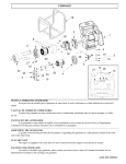
CogniBlox Hardware User’s Manual Version 1.2.9 Revised 10/07/2013 Limitation of Liability CogniMem Technologies, Inc. (CTI) assumes no liability whatsoever and disclaims any express, implied or statutory warranty relating to the product described in this manual and accompanying materials (“Product”) including, but not limited to, the implied warranty of merchantability, fitness for a particular purpose, or non-infringement. In no event shall CTI be liable for any direct, indirect, consequential, punitive, special or incidental damages (including, without limitation, damages for loss of profits, business interruption, or loss of information) arising out of the use or inability to use the Product, even if CTI has been advised of the possibility of such damages. CTI makes no representations or warranties with respect to the accuracy or completeness of the contents of this document and reserves the right to make changes to specifications and product descriptions at any time without notice. This Product is not designed, manufactured or intended by CTI for incorporation into products intended for use or resale in equipment in hazardous, dangerous to life or potentially life-threatening environments, such as in the operation of nuclear facilities, aircraft navigation or communication systems or direct life support machines, in which the failure of products could lead directly to death, personal injury or severe physical or environmental damage (“High Risk Activities”). The inclusion of the Product as critical component in High-Risk Activities implies that the manufacturer assumes all risk of such use and in doing so agrees to fully indemnify CTI for any damages resulting from such application. Trademarks and Copyrights This manual is copyrighted and published by CogniMem Technologies, Inc. All rights reserved. No parts of this work may be reproduced in any form or by any means - graphic, electronic, or mechanical, including photocopying, recording, taping, or information storage and retrieval systems - without the written permission of the publisher. Products that are referred to in this document may be either trademarks and/or registered trademarks of the respective owners. The publisher and the author make no claim to these trademarks. Contact Information www.cognimem.com CogniBlox Hardware Manual 2/20 A. Table of Contents A. TABLE OF CONTENTS.............................................................................................................3 B. GETTING STARTED ................................................................................................................5 1.B. CONFIGURE A SINGLE BOARD OR A STACK OF BOARDS ......................................................................... 5 2.B. TESTING A SINGLE BOARD OR A STACK OF BOARDS ............................................................................. 5 3.B. PROGRAMMING THE BOARD .......................................................................................................... 5 4.B. EXAMPLES OF APPLICATIONS YOU CAN PROGRAM .............................................................................. 6 4.B.a. Stack of CogniBlox for Data Mining ................................................................................. 6 4.B.b. CogniBlox for Video Analytics .......................................................................................... 6 4.B.c. CogniBlox for Complex Recognition ................................................................................. 7 4.B.d. CogniBlox for Sensor Fusion ............................................................................................. 7 C. HARDWARE DESCRIPTION.....................................................................................................8 1.C. OVERVIEW .................................................................................................................................. 8 1.C.a. Bank of CM1K chips.......................................................................................................... 8 1.C.b. Field Programmable Gate Array ...................................................................................... 9 1.C.c. Bank of MRAMs ............................................................................................................... 9 1.C.d. FTDI USB chip ................................................................................................................... 9 2.C. CONNECTIVITY AND I/OS ............................................................................................................ 10 2.C.a. Power supply .................................................................................................................. 10 2.C.b. Spine connectors ............................................................................................................ 10 2.C.c. General purpose switch (SW1) ....................................................................................... 12 2.C.d. Cardinal connectors and switches.................................................................................. 12 2.C.e. JTAG (J9)......................................................................................................................... 13 2.C.f. LEDs ................................................................................................................................ 13 3.C. DEFAULT SETTINGS SUMMARY...................................................................................................... 14 D. FIRMWARE AT FACTORY DEFAULT ......................................................................................15 1.D. ADDRESS MAPPING .................................................................................................................... 15 2.D. USB COMMUNICATION PROTOCOL ............................................................................................... 15 2.D.a. Write protocol ............................................................................................................... 15 2.D.b. Read protocol ................................................................................................................. 15 3.D. EXAMPLES ................................................................................................................................ 16 4.D. COGNIMEM CONTROLLER ........................................................................................................... 16 4.D.a. Command and control lines ........................................................................................... 16 4.D.b. Registers......................................................................................................................... 17 E. EXAMPLES OF COGNIBLOX FIRMWARE ARCHITECTURE ........................................................18 1.E. 2.E. F. COMBINED VISION AND SOUND RECOGNITION ................................................................................ 18 MULTI SCALE IMAGE RECOGNITION ............................................................................................... 19 MECHANICAL AND ELECTRICAL SPECIFICATIONS ..................................................................20 G. SCHEMATICS OVERVIEW .....................................................................................................20 CogniBlox Hardware Manual 3/20 CogniBlox Hardware Manual 4/20 B. Getting Started 1.B. Configure a single board or a stack of boards - - 2.B. 1 Single board configuration: pin#7 of SW1 is down pin#8 of SW1 is down pin#8 of SW2 is down Multiple boards configuration: All boards pin#7 of SW1 is up master board pin#8 of SW1= down slave board pin#8 of SW1 = up If top or bottom board of a stack pin#8 of SW2 = down If in-between board of a stack Pin#8 of the SW2 = up Testing a single board or a stack of boards Connect the CogniBlox board to your PC through its USB connector and wait until the new device is detected. Follow the instructions on screen. The FTDI driver is supplied in the folder CBX/USB Drivers. Install the CogniBlox_Diagnostics program. The following panel will appear and the Connect button should be green if the board is properly detected. The default module targets the CM1K chip. Reading the register 6 must return the value 2 at factory settings. For more testing, refer to the technical brief CM1K_Getting_Started_Programmers.pdf. The list of the CM1K registers is supplied in the paragraph “Register Descriptions” of the CM1K Hardware Manual. Examples of Read/Write sequences to learn and recognize a vector are described in the paragraph “Programming Sequences” of the CM1K Hardware manual. Test Capacity automatically commits all the neurons of the four CM1K chips and reads their number back. It should report the value 4096 at the end of the test. Test Commit automatically loads a user-defined number of neurons with random patterns The Loop Write and Loop Read functions execute a user-defined number of read or write instructions and stop if any communication error occurs. 2 3 4 5 6 3.B. Programming the board The FPGA can be programmed using Lattice’s Diamond software which is available as a download from the Lattice website for both Windows and Linux. Once downloaded and installed, it can be used with either a free license or a subscription license. CogniBlox Hardware Manual 55/20 The default firmware programmed on the FPGA at factory settings implements a simple Register Transfer Level protocol to access the chain of the four CM1K chips. It is described in the next chapter. 4.B. Examples of applications you can program 4.B.a. Stack of CogniBlox for Data Mining Recognize and classify of vectors against large datasets or knowledge bases. 4.B.b. CogniBlox for Video Analytics Process images N times faster by distributing the recognition to multiple CM1K chips. Example1: The four quadrants of a high resolution image are recognized in parallel by four neural networks (of 1024 neurons or more) loaded with the same knowledge. The latter can be simple and just intended to recognize edges or simple objects, or it can be more complex and composed of neurons assigned to different contexts to build a decision based on multiple features. Example2: The image is recognized in parallel at four different scales: Expert at Scale1 (RE1+kn) Expert at Scale2 (RE2+kn) Expert at Scale3 (RE3+kn) Expert at Scale4 (RE4+kn) The same knowledge is loaded in the four CM1Ks. CogniBlox Hardware Manual 66/20 4.B.c. CogniBlox for Complex Recognition Build robust diagnostics using multiple recognition engine and hypothesis generation Example: Expert in color (RE1+kn1) Expert in texture (RE2+kn2) Expert in shapes (RE3+kn3) Expert in cell biology (RE4+kn4) 4.B.d. CogniBlox for Sensor Fusion Multiple sensor inputs (video, sound, accelerometer) for composite recognition. Example1: Robust recognition of a person based on its iris and fingerprint and if the person has authorized access to the “appliance” detection of its emotions based on its facial expression and tone of voice. Expert in voice (RE1+kn1) Expert in face expression (RE2+kn2) Expert in fingerprint (RE3+kn3) Expert in iris(RE4+kn4) CogniBlox Hardware Manual 77/20 C. Hardware Description 1.C. Overview 1.C.a. Bank of CM1K chips - - 4 CM1K chips with 1024 neurons each The four chips can be configured to work independently from one another or to be daisy-chained to build one or multiple networks with more than 1024 neurons. Furthermore, one of the network can also be daisy-chained to additional CM1Ks residing on stacked CogniBlox boards through the spine connector. The configuration of the neural networks is defined by the firmware loaded in the FPGA. This firmware can be programmed to implement a single given configuration or to take advantage of the general-purpose switch inputs to define multiple configurations. CogniBlox Hardware Manual 88/20 i) Examples of possible network configurations for the first board of a stack CM1K_1 DCI DCO Vcc Wire1 CM1K_2 DCI DCO Wire1 Wire2 CM1K_3 DCI DCO Wire2 Wire3 CM1K_4 DCI DCO Wire3 N/A Spine DCI Vcc Wire1 Wire1 Wire2 Wire2 Wire3 Wire3 Wire4 Wire4 Vcc N/A Vcc Wire2 Wire2 Wire3 Wire3 N/A Vcc Wire1 Vcc Wire2 Wire2 Wire3 Wire3 N/A Wire1 Vcc N/A Vcc Wire2 Wire2 Wire3 Wire3 Wire4 Wire4 Vcc Wire1 Wire1 N/A Vcc Wire3 Wire3 N/A Vcc Wire1 Wire1 Wire2 Vcc Wire3 Wire3 N/A Wire2 Vcc Wire1 Wire1 N/A Vcc Wire3 Wire3 Wire4 Wire4 Description 1 network of 4096 neurons expandable 1 network of 4096 neurons expandable 1 network of 1024 neurons 1 network of 3072 neurons 1 network of 1024 neurons 1 network of 3072 neurons 1 network of 1024 neurons 1 network of 3072 neurons 1 network of 2048 neurons 1 network of 2048 neurons 1 network of 2048 neurons 1 network of 2048 neurons 1 network of 2048 neurons 1 network of 2048 neurons (1+2+3+4), non (1+2+3+4), (1) and (2+3+4) (1) expandable and (2+3+4) (1) and (2+3+4) expandable (1+2) and (3+4) (1+2) expandable and (3+4) (1+2) and (3+4) expandable 1.C.b. Field Programmable Gate Array - Lattice XP2 FPGA with 40,000 logic elements (Model LFXP2-40E, BGA 484 balls) Programmable through a JTAG connector, USB connector or 2 SPI lines. 1.C.c. Bank of MRAMs - Two 2 Mbytes (2M x16bits) MRAM, 35 ns access time 1.C.d. FTDI USB chip The FT232H is a single channel USB 2.0 Hi-Speed (480Mb/s) to UART/FIFO IC. It has the capability of being configured in a variety of industry standard serial or parallel interfaces. It must be configured as a single channel synchronous 245 FIFO hardware interface mode (FT245) and interfaces through a Virtual Com port or D2XX Direct driver. CogniBlox Hardware Manual 99/20 2.C. Connectivity and I/Os 2.C.a. Power supply - A single CogniBlox can be powered through its USB power supply, otherwise you will need to use an external 24v power supply. The 24v power supply is connected to a hot swap circuitry. o In case of power shut down, the power backup time lasts approximately 5 ms and is generous enough to allow saving the contents of the neurons to the MRAM provided that this feature is programmed in the firmware of the FPGA. i) 5V Source Select (J13) This jumper requires a jumper connector to be present in order for power to be delivered to the board. A Jumper across 1-2 sources power to the card from the USB connector (single board configuration only). A jumper across 2-3 sources power from the on board 24V to 5V Regulator. Pin # 1 2 3 ii) Pin Name VBUS 5V VOUT 24V Source Connector (J10) This header is a poke-home connector for connecting the board to an external 24v power supply. Insert strip wires into the bottom portion of the connector as described in the table below. To release the wires, you will need push a small wire in the upper holes of the connector. Pin # 1 (+) 2 (-) Pin Name 24V Ground 2.C.b. Spine connectors - The spinal connectors enable the vertical stack ability of the CogniBlox modules and the expansion of the neural network by connecting the CM1K chips from multiple boards on a same parallel bus. The top side connectors are 2 “spinal” spring-loaded 18-pin connectors. The bottom side connectors are simple pads mirroring the top connectors, except for the daisy-chain in (DCI) signal of J8 which becomes the daisy-chain out (DCO) signal on J6. Warning: If you probe the signals of the spinal connectors J6 and J8, DO NOT short pins 1 and 2 which are the 24v VCC lines. CogniBlox Hardware Manual 1010/ 20 i) Spine connector North Top (J5) Pin # 1 3 5 7 9 11 13 15 17 ii) Pin Number 2 4 6 8 10 12 14 16 18 Pin Name CMB_D00 CMB_D01 CMB_D02 CMB_D03 CMB_D04 CMB_D05 CMB_D06 CMB_D07 Ground Pin Name CMB_D08 CMB_D09 CMB_D10 CMB_D11 CMB_D12 CMB_D13 CMB_D14 CMB_D15 Ground Pin Number 2 4 6 8 10 12 14 16 18 Pin Name 24V CMB_RDY CMB_CLK CMB_IDn CMB_UNCn CMB_DS CMB_RWn CMB_DCO CMB_RSTn Pin Number 2 4 6 8 10 12 14 16 18 Pin Name 24V CMB_RDY CMB_CLK CMB_IDn CMB_UNCn CMB_DS CMB_RWn CMB_DCI CMB_RSTn Pin Number 2 4 6 8 10 12 14 16 18 Spine connector South Top (J6) Pin # 1 3 5 7 9 11 13 15 17 iv) Pin Name CMB_D08 CMB_D09 CMB_D10 CMB_D11 CMB_D12 CMB_D13 CMB_D14 CMB_D15 Ground Spine connector North Bottom (J7) Pin # 1 3 5 7 9 11 13 15 17 iii) Pin Name CMB_D00 CMB_D01 CMB_D02 CMB_D03 CMB_D04 CMB_D05 CMB_D06 CMB_D07 Ground Pin Name 24V CMB_SP0 CMB_CSn CMB_BSY CMB_R0 CMB_R1 CMB_R2 CMB_R3 CMB_R4 Spine connector South Bottom (J8) Pin # 1 3 5 7 9 11 13 15 17 CogniBlox Hardware Manual Pin Name 24V CMB_SP0 CMB_CSn CMB_BSY CMB_R0 CMB_R1 CMB_R2 CMB_R3 CMB_R4 1111/ 20 2.C.c. General purpose switch (SW1) The switch SW1 allows defining the configuration and operation of the board through external switch positions, provided that the firmware loaded in the FPGA takes these inputs into considerations. Pin # 1 3 5 7 9 11 13 15 Pin Name Ground Ground Ground Down, Single board Up, Stackable board Ground Ground Ground Ground Pin Number 2 4 6 8 10 12 14 16 Pin Name TBD TBD TBD Down, Master board Up, Slave board TBD TBD TBD TBD 2.C.d. Cardinal connectors and switches Four configurable “cardinal” connectors allow interfacing the board with sensors and other I/O devices including other CogniBlox boards or stacks. The connector is an 8-pin push-in connector and its electrical properties are defined through an associated dip switch. North East South West Connector J1 J4 J2 J3 Configuration Switch SW2 SW5 SW3 SW4 The switch configuration allows for 3 differential pairs and 2 single-ended wires, or eight singleended wires: The differential pairs can be LVDS. They require that the switch between their lines is closed. CogniBlox Hardware Manual The single-ended wires can be used to connect I2C, SPI or other signals. 1212/ 20 i) Cardinal Connector All four cardinal connectors have the following pin assignment: Pin # 1 2 3 4 5 6 7 8 ii) Pin Name User defined, 3.3V User defined, 3.3V User defined, 2.5V User defined, 2.5V User defined, 2.5V User defined, 2.5V User defined, 2.5V User defined, 2.5V Cardinal Switch The pin assignment of the four cardinal switches may defer slightly as described in the table below: Pin # 1 3 5 7 9 11 13 15 Pin Name 3.3V 3.3V S0 S1 (2) S2 No Connect No Connect No Connect Pin Name I2C_SDA I2C_SCL S0 (2) S1 (1) S2 No Connect No Connect No Connect Pin # 2 4 6 8 10 12 14 16 (1) On the North switch (SW2) pin#8 is reserved to define if the pull-up resistors shall be enabled or not. Pin#8 must be down for the bottom and top boards of a stack. (1) On the West switch (SW4) pin#8 is reserved to define the boot configuration of the FPGA (2) On the North switch (SW2) pin#6-7 are reserved to enable the future programming of the FPGA via a USB connection without the need for a Lattice programming cable. 2.C.e. JTAG (J9) - JTAG to program and debug the FPGA Pin # 1 3 5 7 9 2.C.f. Pin Name JTAG_TDI JTAG_TDO JTAG_TCK JTAG_ TMS JTAG_TRST Pin Name VCC (3.3V) No Connect No Connect No Connect Ground Pin # 2 4 6 8 10 LEDs Four sets of three LEDS are placed along the four edges of the board. Their functionality of defined by the firmware programmed on the board. CogniBlox Hardware Manual 1313/ 20 3.C. - - Default settings summary Single board configuration: pin#7 of SW1 is down pin#87of SW1 is down pin#8 of SW2 is down Multiple boards configuration: All boards pin#7 of SW1 is up master board pin#8 of SW1= down slave board pin#8 of SW1 = up If top or bottom board of a stack pin#8 of SW2 = down If in-between board of a stack Pin#8 of the SW2 = up CogniBlox Hardware Manual 1414/ 20 D. Firmware at Factory Default At factory settings, the board is programmed with a simple USB protocol to read and write data to registers or addresses of modules instantiated in the FPGA. The only module instantiated at first is the controller of the chain of 4 CM1K chips residing on the board. 1.D. Address Mapping The default modules instantiated in the board are accessible through the following 32-bit address map: Address Range 0x01000000 0x0100001F Module= Address[30-24] CogniMem 0x01 (d01) 0x10000000 0x0100001F MRAM 0x10 (d16) TBD More to come… 2.D. Functionality defined by registers = Address[23:8] Access to the CM1K neurons to learn and recognize vectors, save and restore knowledge. Also access to the recognition logic in bypass and video mode. Not yet implemented USB communication protocol The communication protocol programmed in the FPGA of the V1KU board is based on the following packet sequence: 2.D.a. Write protocol Reserved 0x00 Address[31:0] Module[6:0] Register[24:0] Bit 31=1 1 byte 1 byte 3 bytes Data length[23:0] Size of the input array expressed in words 3 bytes Data Input array Data length[23:0] Size of the output array expressed in words 3 bytes Data Output array Data length *2 bytes 2.D.b. Read protocol Reserved 0x00 1 byte Bit 31=0 Address[31:0] Module[6:0] Register[24:0] 1 byte CogniBlox Hardware Manual 3 bytes Data length *2 bytes 1515/ 20 3.D. Examples The following examples used dummy modules and registers numbers. i) Single Read Read the register 5 of the module 4 Data is returned into 2 bytes or a word ii) Single Write Write the 16-bit value 0x33AA to the register 5 of the module 4 iii) 0x00 02 23 45 67 00 00 04 Multiple Write Write 4 consecutive byte values 9,8,7,6 starting at the address 0x234567 of the module 0x02 4.D. 0x00 84 00 00 05 00 00 01 33 AA Multiple Read Read 8 consecutive byte values starting at the address 0x234567 of the module 0x02 Data is returned into 8 bytes. iv) 0x00 04 00 00 05 00 00 01 0x00 82 23 45 67 00 00 02 09 08 07 CogniMem controller The CogniMem controller is the module 0x01. It transmits and receives data to and from the chain of CM1K chips residing on the board and possibly extending to the CM1K chips of additional boards stacked on top of this master board. 4.D.a. Command and control lines DS RW_ REG DATA RDY ID_ UNC_ Data strobe line Read/Write line (default is Read with RW_=1) 5 bit register address 16-bit register data Ready control line mixing the ready output signal of all the neurons in the chain and indicating that the neurons are all ready to execute a new command Control line mixing the ready output signal of all the neurons in the chain and indicating that neurons have identified the last vector and that these neurons are all in agreement for its classification. Control line mixing the ready output signal of all the neurons in the chain and indicating that neurons have identified the last vector but that these neurons are in disagreement with its classification. This line is an in/out line because used as an input during the execution of certain Write register. CogniBlox Hardware Manual 1616/ 20 All the neurons of the CM1K chips sample a new command on the positive edge of the system clock and pull down their RDY line for the duration of its execution. Upon completion, the RDY line is pulled back up on the positive edge of the system clock. A Write command (DS, RW_=0, REG, DATA) must be stable on the positive edge of the system clock and released before the next positive edge of the system clock. A Read command (DS, RW_=1, REG) must be stable on the positive edge of the system clock and released before the next positive edge of the system clock. DATA is stable when the RDY control line is pulled high. 4.D.b. Registers For more information about the CogniMem registers and programming examples, refer to the CM1K hardware user’s manual and the CogniMem technology Reference Guide. Register Hex Description CM_NCR CM_COMP CM_LCOMP CM_INDEXCOMP CM_DIST 0x00 0x01 0x02 0x03 0x03 Neuron Context Component Last Component Component Index Distance CM_CAT 0x04 Category CM_AIF 0x05 Active Influence Field CM_MINIF CM_MAXIF 0x06 0x07 Minimum Influence Field Maximum Influence Field CM_NID CM_GCR CM_RESET CHAIN CM_NSR CM_FORGET 0x0A 0x0B 0x0C 0x0D 0x0F CM_NCOUNT CM_RSR CM_RTDIST 0x0F 0x1C 0x1D Neuron identifier Global Norm and Context Point to the 1st neuron in SR mode Network Status Register Clear the neuron registers, the Minif, Maxif and GCR global registers. Does NOT reset the NSR register. Return the number of committed neurons Recognition Status Register Real-Time distance CM_RTCAT 0x1E Real-Time category CM_LEFT CM_TOP CM_NWIDTH(1) CM_NHEIGHT(1) CM_BWIDTH(1) CM_BHEIGHT(1) CM_ROIINIT 0x11 0x12 0x13 0x14 0x15 0x16 0x1F Left position of the ROI Top position of the ROI Width of the ROI Height of the ROI Width of the inner block Height of the inner block Reset the ROI to default CogniBlox Hardware Manual Def ault 0 0 0 0 0xFF FF 0xFF FF 0x4 000 2 0x4 000 0 1 0 0 0xFF FF 0xFF FF 200 120 340 220 20 20 Access R/W in SR mode W, R/W in SR mode W, R/W in SR mode W R R/W R/W in SR mode R/W R/W R W W R/W W R R/W R R R/W R/W R/W R/W R/W R/W W 1717/ 20 E. Examples of CogniBlox firmware architecture 1.E. Combined vision and sound recognition In the following example, a video recognition engine receives input from a camera on the North bus and interfaces to a chain of 3 CM1Ks to the recognize the contents of the video frames. The output is transferred to a decision rule shared with the Voice recognition engine. A voice recognition engine receives input from a microphone on the West bus and interfaces to a single CM1K to the recognize a voice. The output is transferred to a decision rule shared with the Video recognition engine. CogniBlox Hardware Manual 1818/ 20 2.E. Multi scale image recognition In the following example, the same video signal received on the North bus is transmitted to three different Video Recognition engines which are each interfaced to their own CM1K chip. These engines can be designed to recognize the video frames at different scales, or with different feature extraction methods, or with different regions of search, etc. The outputs of the three engines are transmitted to a decision rule engine which assembles them into a feature vector and uses a CM1K chip to classify this vector as a global response. CogniBlox Hardware Manual 1919/ 20 F. Mechanical and Electrical Specifications Power supply: Power consumption: G. 24v 50 mA per board Schematics Overview CogniBlox Hardware Manual 2020/ 20