1
Megohmmeters
Model 1020
Model 1025
Chauvin Arnoux, Inc. d.b.a. AEMC® Instruments
99-MAN-100110 Rev 02 06/97
Megohmmeters
Model 1020
Model 1025
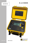
USER MANUAL
MEGOHMMETER
MODEL 1025
MΩ
DATA HOLD
OFF
ON
MΩ
TIMER
Man.
3 Min.
!
250 V
500 V
1000 V
Ω
~
VAC
TEST
MΩ
~ /Ω
VAC
- Line
+ Earth
Owner’s Record
The serial number for the Megohmmeter Model 1020 or Model 1025
is located on the back of the instrument. Please record this number
and purchase date for your records.
MEGOHMMETER MODEL 1020
CATALOG # 2111.91
SERIAL #:
PURCHASE DATE:
DISTRIBUTOR:
MEGOHMMETER MODEL 1025
CATALOG # 2111.87
SERIAL #:
PURCHASE DATE:
DISTRIBUTOR:
99-MAN-100110
2nd Revision
Printed 07/97
AEMC® Instruments
by Chauvin Arnoux, Inc.
Table of Contents
Warning . . . . . . . . . . . . . . . . . . . . . . . . . . . . . . . . . . . . . . . . . . . .2
International Electrical Symbols . . . . . . . . . . . . . . . . . . . . . . . . . .2
Receiving Your Shipment . . . . . . . . . . . . . . . . . . . . . . . . . . . . . . .3
Packaging . . . . . . . . . . . . . . . . . . . . . . . . . . . . . . . . . . . . . . . . . .3
Description . . . . . . . . . . . . . . . . . . . . . . . . . . . . . . . . . . . . . . . . . .3
Features . . . . . . . . . . . . . . . . . . . . . . . . . . . . . . . . . . . . . . . . . . .4
Specifications . . . . . . . . . . . . . . . . . . . . . . . . . . . . . . . . . . . . . . . .5
Safety Check/Voltage Test . . . . . . . . . . . . . . . . . . . . . . . . . . . . . .9
Insulation Resistance Testing (MΩ Range) . . . . . . . . . . . . . . . . . .9
Test Voltage . . . . . . . . . . . . . . . . . . . . . . . . . . . . . . . . . . . .9
Spot Testing . . . . . . . . . . . . . . . . . . . . . . . . . . . . . . . . . . .10
Ratio Testing . . . . . . . . . . . . . . . . . . . . . . . . . . . . . . . . . . .10
For Successful Insulation Resistance Testing . . . . . . . . . . .11
Insulation Measurement - Connections . . . . . . . . . . . . . . .12
Insulation Resistance Measurements on Motors . . . . . . . .15
Continuity Measurements . . . . . . . . . . . . . . . . . . . . . . . . . . . . . .16
Resistance Measurements . . . . . . . . . . . . . . . . . . . . . . . . . . . . .17
Data Hold . . . . . . . . . . . . . . . . . . . . . . . . . . . . . . . . . . . . . . . . . .18
Timer . . . . . . . . . . . . . . . . . . . . . . . . . . . . . . . . . . . . . . . . . . . . .18
Maintenance . . . . . . . . . . . . . . . . . . . . . . . . . . . . . . . . . . . . . . .19
Repair and Calibration . . . . . . . . . . . . . . . . . . . . . . . . . . . . . . . .20
(North/South America, Australia, New Zealand) . . . . . . . . .20
(Europe, Asia, Africa) . . . . . . . . . . . . . . . . . . . . . . . . . . . .21
Technical and Sales Assistance . . . . . . . . . . . . . . . . . . . . . . . . .22
Limited Warranty . . . . . . . . . . . . . . . . . . . . . . . . . . . . . . . . . . . .23
Warning
These safety warnings are provided to ensure the safety of personnel and proper operation of the instrument.
•
Read this instruction manual completely before attempting to
use or service this instrument and follow all safety information.
•
Safety is the responsibility of the operator!
•
Tests are to be carried out only on dead circuits! Check for live
circuits before making resistance measurements (safety
check).
•
Always make connections from the instrument to the circuit
under test.
•
The Megohmmeter Models 1020 and 1025 are sources of high
voltage, as is the sample connected to them. All persons performing or assisting in the tests must employ all safety precautions to prevent electrical shock to themselves and to others.
•
AEMC® considers the use of rubber gloves to be an excellent
safety practice even if the equipment is properly operated and
correctly grounded.
•
When testing capacitance samples, make sure that they have
been properly discharged and that they are safe to touch.
Dielectric insulation samples should be short-circuited for at
least five times the amount of time they were energized.
•
Never open the back of the instrument while connected to any
circuit or input.
International Electrical Symbols
!
2
This symbol signifies CAUTION! and requests that the user
refer to the user manual before using the meters.
Megohmmeter Models 1020 and 1025
Receiving Your Shipment
Upon receiving your shipment, check to be sure that the contents
agree with the packing slip. Notify your distributor at once of any
shortages. If the equipment appears to be damaged, file a claim
immediately with your carrier, and notify your distributor at once, giving a detailed description of the damages. Save the damaged packing container to substantiate your claims.
Packaging
Megohmmeters Model 1020 (Cat. #2111.91) and Model 1025 (Cat.
#2111.87) are shipped with a carrying case, two color-coded leads,
six 1.5 V “AA” batteries, and an instruction manual.
Description
Model 1020 and Model 1025 are compact, light-weight, battery-operated, digital megohmmeters. The Model 1020 tests at 250 V and 500
V up to 200 MΩ. The Model 1025 adds an additional voltage range of
1000 V, and measures up to 2000 MΩ.
The Models 1020 and 1025 also feature a continuity test range with
an audible beeper for resistances under 100Ω, and a 600 V AC range
for safety voltage check.
The press-to-test button has an associated locking feature for continuous tests up to three minutes, eliminating the need to hold down the
button manually.
Other features include a large 3-1/2 digit LCD, automatic zero, data
hold switch, and low battery indicator. These light-weight, easy-to-use
megohmmeters can be used for most commonly performed insulation
tests, such as on cables, switch gear, motors, DC generators, power
tools, and small appliances.
The Models 1020 and 1025 include test leads, batteries, carrying
case, and user manual.
Megohmmeter Models 1020 and 1025
3
Models 1020/1025 Features
•
Model 1020 measures insulation at 250 and 500 V.
•
Model 1025 measures insulation at 250, 500, and 1000 V.
•
Continuity test
•
Continuity beeper
•
600 V AC safety test voltage range
•
Large, easy-to-read digital display
•
Data hold switch
•
Three-minute “lock-on” test button for hands-free operation
•
Automatic discharge when test button is released
•
Low battery indication
4
Megohmmeter Models 1020 and 1025
Models 1020/1025 Specifications
ELECTRICAL SPECIFICATIONS
INSULATION TESTS
DC Test Voltage:
250 V and 500 V (Model 1020)
250, 500, 1000 V (Model 1025)
Megohm Range:
0.1 to 200 MΩ (Model 1020 and 1025)
1 to 2000 MΩ (Model 1025 @ 1000 V)
Resolution:
250 and 500 V : 0.1 MΩ
1000 V : 1 MΩ
Short Circuit Current:
0.4 mA max. at 250 V
0.9 mA max. at 500 V
1.7 mA max. at 1000 V
Accuracy:*
0.1 to 1000 MΩ: 3% of reading ± 3 digits
1000 to 2000 MΩ: 5% of reading ± 3 digits (Model 1025 only)
Test Voltage Generation:
Solid state circuitry generating test voltage (± 10%).
RESISTANCE TESTS (Ω)
Range: 0.1 to 200Ω
Accuracy:* 1% of reading ± 2 digits
Maximum Open Circuit Voltage: 3.3 V
Overload Protection: 500V DC/AC
*Accuracies are at 23° C ± 5° C, below 80% RH
Megohmmeter Models 1020 and 1025
5
CONTINUITY TESTS (Ω)
Range: 0 - 100Ω (with
HO
display and beeper)
Resolution: 0.1Ω
Operation Resistance: < 100Ω
Max. Open Circuit Voltage: 3.2 V
Overload Protection: 500 V DC/AC
~
VOLTAGE TESTS SAFETY CHECK (VAC
)
Range: 0 - 600 V AC
Resolution: 1 V
Accuracy:* 0.8% of reading ± 3 digits
Input Impedance: 10 MΩ
GENERAL SPECIFICATIONS
Power Supply: Six 1.5 V “AA” batteries
Low Battery Indication: Indicator on LCD
Display: 3-1/2 digit LCD, 0.65” height
Overrange Indicator: Highest digit of (1) displayed
Operating Temperature: 32° to 104°F (0° to 40°C)
Storage Temperature: 14° to 140°F (-10° to 60°C)
Operating Humidity: 0 - 80% RH
Storage Humidity: 0 - 70% RH
Dimensions: 6.5 x 3.9 x 2.2” (165 x 100 x 57mm)
Weight: 1.1 lb (500 g) approx.
*Accuracies are at 23° C ± 5° C, below 80% RH
6
Megohmmeter Models 1020 and 1025
Model 1020
Ω
Ω
Ω
Ω
Ω
Figure 1
1. Digital Display
2. Data Hold Switch
3. Manual and Lock Switch
(locks power on for 3 minutes)
Megohmmeter Models 1020 and 1025
4. Press-to-Test Button
5. Range Selector Switch
6. Test Terminals
7
Model 1025
MEGOHMMETER
MODEL 1025
MΩ
DATA HOLD
OFF
ON
MΩ
TIMER
Man.
3 Min.
!
250 V
500 V
1000 V
Ω
~
VAC
TEST
MΩ
~ /Ω
VAC
- Line
+ Earth
Figure 2
1. Digital Display
2. Data Hold Switch
3. Manual and Lock Switch
(locks power on for 3 minutes)
8
4. Press-to-Test Button
5. Range Selector Switch
6. Test Terminals
Megohmmeter Models 1020 and 1025
Safety Check - Voltage Test
NOTE: Make sure the jacks are firmly inserted into the megohmmeter prior to performing any electrical tests!
Before measuring insulation resistance, confirm that the sample is
fully discharged (particularly in dielectric and capacitance samples),
and that the sample is not connected to an energized circuit. To perform the voltage test:
1) Insert the red lead into the +earth position and the black lead in the
middle jack position.
2) Set the range selection switch to the VAC position.
3) Connect to the sample
under test.
MΩ
~ /Ω
VAC
- Line
+ Earth
4) Press the test button.
Figure 3
Insulation Resistance Testing (MΩ Range)
After checking for a live circuit (see Safety Check), connect the
megohmmeter. See Figures 4 through 11 for examples.
TEST VOLTAGE
No published standard tells which voltage to choose for any given
winding. However, published recommendations are summarized as
follows:
Rated Voltage of Motor
Test Voltage
Below 115
250 V
115
250 V or 500 V
230
500 V
460
500 V or 1000 V
Megohmmeter Models 1020 and 1025
9
SPOT TESTING
As a general rule in spot testing, test voltage should be applied until
no variation in reading is noted for 15 seconds, or applied for a fixed
60 seconds. What minimum value should be measured? The IEEE
standard No. 43-1974 states that it is impossible to specify the value
of insulation resistance at which a winding will fail electrically, but on
motors, minimum readings generally stated are:
Rated Voltage
R Minimum
250 or less
2 MΩ
460
2 MΩ
There is no fixed figure for determining what is good and bad in resistance readings, but a good guide would be 1 megohm for every 100
applied operating volts, as a minimum figure. This applies to motors
and transformers. When the insulation resistance gets this low, an
electrical breakdown can be expected at any time, and rewinding or
replacing should be considered.
It is not unusual for a winding to be 10 to 100 times the recommended minimum value (IEEE standard 43-1974: Recommended Practice
for Testing Insulation Resistance of Rotating Machinery), but this
varies with temperature and humidity.
RATIO TESTING
In time resistance testing (Dielectric Absorption Ratio), readings are
taken at 30 and 60 seconds to obtain the dielectric absorption ratio.
Insulation resistance @ 60s = Dielectric Absorption Ratio (DAR)
Insulation resistance @ 30s
This test is useful to increase the accuracy of spot testing. In general, a ratio of 1.5 or better should be required. A ratio below this indicates that repair is probably needed.
10
Megohmmeter Models 1020 and 1025
Remember, a DC insulation test may be used for acceptance testing,
but is more commonly used to check the gradual deterioration of
equipment over its life. Consult your equipment manufacturer for specific test or test voltage if not known.
Insulation resistance decreases with moisture, temperature and age and
should be recorded over time at a given temperature and corrected.
FOR SUCCESSFUL INSULATION RESISTANCE TESTING
•
Check with the equipment manufacturer for factory insulation
resistance readings.
•
Do not rely on insulation resistance testing alone as proof of
winding conditions.
•
Do not expect the same value for all parts of all machines.
•
Observe consistent test time duration, recognizing that total
current through insulation under test will vary with time.
•
Correct all readings properly to a standard reference temperature
(see IEEE Std. #43-1974, Temperature Correction Curve).
•
Know what you are testing. Isolate the piece of equipment from
other circuitry.
•
Watch trends rather than relying on single “spot” readings.
Megohmmeter Models 1020 and 1025
11
INSULATION MEASUREMENT - CONNECTIONS
Figure 4 shows the connections to measure the insulation of one conductor to the other conductors. The cable should be disconnected at
both ends to avoid leakage through switchboards and panels.
Conductor Under Test
Cable Insulation
MEGOHMMETER
MODEL 1025
MΩ
DATA HOLD
OFF
ON
MΩ
TIMER
Man.
3 Min.
!
250 V
500 V
1000 V
Ω
~
VAC
TEST
MΩ
~ /Ω
VAC
- Line
–
+ Earth
+
Figure 4
12
Megohmmeter Models 1020 and 1025
Figures 5 and 6 show the connections for testing insulation from a
supply conductor to ground (motor frame).
Conductor Under Test
Cable Insulation
MEGOHMMETER
MODEL 1025
MΩ
DATA HOLD
OFF
ON
MΩ
TIMER
Man.
3 Min.
!
500 V
250 V
1000 V
Ω
~
VAC
TEST
MΩ
~ /Ω
VAC
- Line
+ Earth
–
+
Figure 5
Conductor Under Test
Cable Insulation
MEGOHMMETER
MODEL 1020
Ω
DATA HOLD
OFF
ON
MΩ
TIMER
Man.
3 Min.
250 V
500 V
Ω
~
VAC
TEST
MΩ
~ /Ω
VAC
- Line
Figure 6
Megohmmeter Models 1020 and 1025
–
+ Earth
+
13
Figure 7 shows the connections to a transformer (lighting or distribution). Make
sure that the switches
and/or circuit breakers on
both sides are open. Check
the high voltage winding to
ground, low voltage to
ground, and the resistance
between them with no winding grounded.
Tested
Winding
Transformer
Grounding Lug
MEGOHMMETER
MODEL 1020
Figure 7
Ω
DATA HOLD
OFF
ON
MΩ
TIMER
Man.
3 Min.
250 V
500 V
Ω
~
VAC
TEST
MΩ
~ /Ω
VAC
- Line
Jumpers
MEGOHMMETER
MODEL 1020
90.6
Ω
DATA HOLD
OFF
ON
MΩ
TIMER
Man.
3 Min.
250 V
500 V
Ω
~
VAC
TEST
MΩ
~ /Ω
VAC
- Line
+ Earth
–
14
+
Figure 8
+ Earth
-
+
Figure 8 shows the connections
for measuring the insulation of a
three-phase line to ground by
connecting the jumpers between
phases. This gives a reading of
all conductors at once. If a load
such as a motor, heater, etc., is
attached to the other end of the
line, it will read the load resistance to ground at the same time.
By removing the jumpers, readings can be made between the
individual
conductors
and
ground.
Megohmmeter Models 1020 and 1025
INSULATION RESISTANCE MEASUREMENTS ON MOTORS
Figure 9 shows reading
the resistance to ground of
a three-phase motor winding. Since the three-phase
motors are internally connected, it is only necessary to connect one lead to
the motor lead and the
other lead to the motor
frame as shown.
MEGOHMMETER
MODEL 1025
MΩ
DATA HOLD
OFF
ON
MΩ
TIMER
Man.
3 Min.
!
250 V
500 V
1000 V
Ω
~
VAC
TEST
MΩ
~ /Ω
VAC
- Line
Figure 9
MEGOHMMETER
MODEL 1020
Ω
DATA HOLD
OFF
ON
MΩ
TIMER
Man.
3 Min.
250 V
500 V
Ω
~
VAC
TEST
MΩ
~ /Ω
VAC
- Line
–
+ Earth
+
–
+ Earth
+
Figure 10 shows the windings of
a three-phase motor separated.
Sometimes this can be done at
the lead terminals, while other
times the end bells must be
removed to get at the lead wires
of the coils. By connecting the
megohmmeter as shown, the
phase insulation resistance
value can now be determined.
Read between phases “A” and
“B”, then “B” and “C”, then “C”
and “A”.
Figure 10
Megohmmeter Models 1020 and 1025
15
Figure 11 shows connections
for testing insulation from a
supply conductor in a switchbox to ground (motor frame).
An identical test may be carried out from the motor
starter.
MEGOHMMETER
MODEL 1025
MΩ
DATA HOLD
OFF
ON
MΩ
TIMER
Man.
3 Min.
!
250 V
500 V
1000 V
Ω
~
VAC
TEST
MΩ
~ /Ω
VAC
- Line
–
+ Earth
+
Figure 11
Continuity Measurements
Once it has been verified that no voltage is present, the continuity
check may be performed.
Set the switch to the Ω position.
Connect the red lead in the +earth position and the black lead in the
middle jack position.
MΩ
~ /Ω
VAC
- Line
+ Earth
Figure 12
16
Megohmmeter Models 1020 and 1025
When the resistance is less than 100Ω it will be indicated by a continuous beeper.
If an open circuit has been detected the display will read:
HOLD
Ω
Figure 13
Resistance Measurements
Set the switch to the Ω position.
Connect the red lead in the +earth position and the black lead in the
middle jack position.
MΩ
~ /Ω
VAC
- Line
+ Earth
Figure 14
The instrument has a measurement range of 0.1 to 200Ω
Connect the leads to the device under test.
If an open circuit has been detected the display will read:
HOLD
Ω
Megohmmeter Models 1020 and 1025
Figure 15
17
Data Hold
Will hold last measured value in memory when the Data Hold position
is in the “ON” position. NOTE: You must hold down the yellow test
button to keep the value displayed. The value in memory will still be
displayed if leads are disconnected as long as the yellow test button
is depressed.
Timer
The instrument may be used in a “hands-free operation” by moving
the timer switch to the three minute position and then pressing the
yellow test button. If the yellow test button is pressed when the switch
is in the three minute position it will shut the instrument off. NOTE:
After three minutes all data will be lost! If a DAR (Dielectric Absorption
Ratio) test is performed the user will have to record the value after 30
seconds and 60 seconds.
Insulation resistance @ 60s
= Dielectric Absorption Ratio (DAR)
Insulation resistance @ 30s
CAUTION: The timer will keep the output leads energized for three
minutes. After three minutes the display will go blank and all measured data will disappear.
This instrument was not designed to perform a Polarization Index (PI)
Test because the test voltage cannot be locked for 10 minutes. If a PI
Test is required, the user will have to hold down the test button and
record the readings at 1 minute and 10 minutes.
Insulation resistance @ 10 min
= Polarization Index (PI)
Insulation resistance @ 1 min
18
Megohmmeter Models 1020 and 1025
Maintenance
Battery Replacement
Replace batteries only when the megohmmeter is not connected to a
sample and OFF. (including Timer to Man. position).
When battery voltage is not sufficient the low “BT” symbol will be displayed.
Remove the screw from the middle of the instrument and remove the
back cover.
Replace the 6 “AA” batteries.
Reinstall the back cover and screw to secure the back cover.
Megohmmeter Models 1020 and 1025
19
Repair and Calibration
(North/South America, Australia, New Zealand)
To guarantee that your instrument complies with the factory specifications, we recommend that the Megohmmeter Models 1020 and
1025 be submitted to our factory service center at one year intervals
for recalibration, or as required by other standards.
For instrument repair and/or calibration, please call our USA factory,
toll-free, at (800) 945-AEMC (800)-945-2362):
Chauvin Arnoux, Inc.
d.b.a. AEMC® Instruments
15 Faraday Drive
Dover, NH 03820 USA
Tel:
(800) 945-2362
(603) 749-6434
Fax:
(603) 742-2346
www.aemc.com
(Or contact your authorized distributor.)
20
Megohmmeter Models 1020 and 1025
Repair and Calibration
(Europe, Asia, Africa)
To guarantee that your instrument complies with the factory specifications, we recommend that the Megohmmeter Models 1020 and
1025 be submitted to our factory service center at one year intervals
for recalibration, or as required by other standards.
For instrument repair and/or calibration, please call our French factory:
Manumesure - Reux
14130 Pont l’Evêque
France
Tel:
(33) 2 31 64 51 43
Fax:
(33) 2 31 64 51 09
www.aemc.com
(Or contact your authorized distributor.)
Megohmmeter Models 1020 and 1025
21
Technical and Sales Assistance
(North/South America, Australia, New Zealand)
If you are experiencing any technical problems, or require any assistance with the proper use or application of this instrument, please call
our technical hotline:
Chauvin Arnoux, Inc.
d.b.a. AEMC® Instruments
200 Foxborough Blvd.
Foxborough, MA 02035 USA
Tel:
(800) 343-1391
(508) 698-2115
Fax:
(508) 698-2118
www.aemc.com
Technical and Sales Assistance
(Europe, Asia, Africa)
If you are experiencing any technical problems, or require any assistance with the proper use or application of this instrument, please call
our technical hotline:
Chauvin Arnoux
190, rue Championnet
75876 Paris Cedex 18 - France
Tel:
(33) 1 44 85 44 57
Fax:
(33) 1 46 27 95 59
www.aemc.com
22
Megohmmeter Models 1020 and 1025
Limited Warranty
The Megohmmeter Models 1020 and 1025 are warranted to the
owner for a period of 1 year from the date of original purchase against
defects in manufacture. This limited warranty is given by AEMC®
Instruments, not by the distributor from whom it was purchased. This
warranty is void if the Megohmmeter Model 1020 or 1025 has been
tampered with, abused or if the defect is related to service not performed by AEMC® Instruments.
What AEMC® Instruments Will Do: If a malfunction occurs within the
1 year period, you may return the Megohmmeter Model 1020 or 1025
to us for repair or replacement free of charge, provided we have your
REGISTRATION CARD on file. AEMC® Instruments will, at its option,
repair or replace the faulty material.
Note: If a card is not on file, we will require a dated proof of purchase
as well as your REGISTRATION CARD accompanied by the defective material.
What You Must Do: First obtain a return authorization by phone or by fax
from AEMC® Instruments, then return the Megohmmeter Model 1020 or
1025, indicating place and date of purchase, with a written explanation
of the reason for return. Return material, postage pre-paid to:
Chauvin Arnoux, Inc.
d.b.a. AEMC® Instruments
Service Department
15 Faraday Drive
Dover, NH 03820 USA
Tel: (800) 945-2362
(603) 749-6434
Fax (603) 742-2346
Caution: To protect against in-transit loss, we recommend you
insure your returned material.
For full warranty coverage, please read the Warranty Card which is
affixed to the Warranty Registration Card. Please keep the Warranty
Card with your records.
Megohmmeter Models 1020 and 1025
23
NOTES
24
Megohmmeter Models 1020 and 1025
Megohmmeter Models 1020 and 1025
25