1
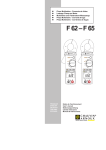
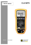
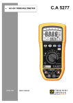
Adapter for pylon ground resistance measurement ENGLISH User’s manual C.A 6474 CAUTION - DANGER! Read the User Manual. In these operating instructions, failure to follow or carry out instructions preceded by this symbol may result in personal injury or damage to the device and the installations. Instrument fully protected by double insulation or reinforced insulation. The rubbish bin with a line through it means that in the European Union, the product must undergo selective disposal for the recycling of electric and electronic material, in compliance with Directive WEEE 2002/96/EC. Earth terminal. Definition of measurement categories Measurement category IV corresponds to measurements taken at the source of low-voltage installations. Measurement category III corresponds to measurements on building installations. Measurement category II corresponds to measurements taken on circuits directly connected to low-voltage installations. Measurement category I corresponds to measurements taken on circuits not directly connected to the network. Thank you for purchasing this C.A. 6474 adapter for pylon ground resistance measurement. To obtain the best service from your unit: read these operating instructions carefully, comply with the precautions for use, that is to say, temperature, humidity, altitude, degree of pollution and site of use. Precautions for Use Only use the accessories supplied with the C.A 6474. Do not use the C.A 6474 or its accessories if they appear damaged. Never exceed the protection limit values indicated in the specification or those indicated for the C.A 6472. The connection of current sensor leads is the last operation to be carried out before starting measurement. Disconnection of these leads from the instrument is the first operation to be carried out once measurement is finished. In general, boots, gloves and insulated mats should be used. CONTENTS 1. Presentation of the instrument.......................................................................................4 2. Initial operation.......................................................................................................................6 2.1. Verification of the contents.................................................................................................6 2.2. Description of the accessories...........................................................................................7 2.3. Characteristics label ..........................................................................................................8 3. Procedure..................................................................................................................................8 4. Technical characteristics ................................................................................................8 4.1. Reference conditions..........................................................................................................8 4.2. Environmental conditions...................................................................................................8 4.3. Electrical characteristics.....................................................................................................9 4.4. Compliance with international norms.................................................................................9 4.5. Electromagnetic compatibility (EMC).................................................................................9 4.6. Mechanical characteristics ................................................................................................9 5. Maintenance.............................................................................................................................10 5.1. Cleaning.............................................................................................................................10 5.2. Calibration testing.............................................................................................................10 5.3. Repair.................................................................................................................................10 6. Warranty...................................................................................................................................10 7. To order.....................................................................................................................................11 7.1. Accessories.......................................................................................................................11 7.2. Spares................................................................................................................................11 C.A 6474 PYLON BOX GROUND TESTER C.A 6472 Connection terminals AmpFLEX 1 4 3 2 50V CAT IV INPUTS 1.2.3.4 1.2.3 1.2 4 3 2 1 INPUT SELECTION Overload Connection to C.A 6472 Connection onto the C.A 6472 S x 1/10 Sx1 S x 10 1 2 3 4 SENSITIVITY C.A 6474 PYLON BOX NUMBER OF TURNS Overload LED Selection of the measurement channels Selection of the sensitivity Selection of the number of turns 1. Presentation of the instrument This adapter has been designed for use with the C.A 6472 earth tester. It enables the earthing of electricity pylons to be measured and verified and, in general, any earthing of a system by a bulky structure, the earthing of which cannot be measured by classic means. 2. Initial operation 2.1. Verification of the contents When unpacking, check that all items have been delivered in line with your order. The instrument and accessories underwent full mechanical and electronic testing before shipment. All necessary precautions have been taken to ensure you receive the instrument in good condition. It is advisable to make a quick check of the equipment to ensure no damage has occurred during transportation. In the event of damage, immediately notify the carrier of the customary reservations. If you need to ship the instrument to another site, the original packaging should preferably be used. x4 Adaptateur pour la mesure de terre des pylônes x5 C.A 6474 x5 FRANÇAIS Notice de fonctionnement x3 x5 x6 2.2. Description of the accessories 1 Shoulder bag that can hold the instrument and all accessories. 2 1 connecting lead. This lead connects the C.A 6472 to the C.A 6474. It enables communication between the 2 instruments and powers the C.A 6474 from the C.A 6472. 4 flexible current sensors (AmpFLEX). You can connect from 1 to 4 sensors on the C.A 6474 according to the earthing structure considered. These sensors enable selective measurement of the current used to calculate the earthing resistance value. Check that each sensor has an identification ring to identify the input channel on the C.A 6474 to which each sensor must be connected. If not, please refer to the C.A 6472 user manual to establish identification. 6 x BNC/BNC cables, 15 metres long. These cables enable the sensors to be connected to the C.A 6474 up to a distance of 30 metres. 1 set of identification rings. These rings should be mounted on BNC/BNC cables to enable the current sensor to be identified up to the connection to the C.A 6474. 2 cables, 5 meters long, black and green. These cables are to be used to connect the "E" and "ES" terminals of the C.A 6472 to the structure being tested via clamps. 5 slotted tongue terminals. 2 slotted tongue terminals are to be screwed onto the above cables. The terminals are then screwed onto the clamps to ensure the connection is stable and efficient. 3 clamps. These clamps are equipped with a retention pin to ensure a stable electrical connection by eliminating corrosion or paint present in the metal contact part. 1 calibration loop. This enables the user to verify and/or calibrate the AmpFLEX sensors and confirm or obtain their identification in relation to the measurement channel used. Please refer to the C.A 6472 user manual for the operating procedure. 5 user manuals and 5 characteristics labels, each in a different language. 3 4 5 6 7 8 9 10 2.3. Characteristics label Stick one of the 5 characteristics labels supplied, in the appropriate language, inside the instrument lid. 3. Procedure Use of the C.A 6474 adapter and accessories, associated with the C.A 6472, is described in detail in the C.A 6472 user manual. 4. Technical characteristics 4.1. Reference conditions Influence quantities Reference values Temperature 20 ± 3 °C Relative humidity 45 to 55% RH Supply voltage (1) 9 to 11.2 V Input signal frequency range 45 to 450 Hz Electrical field < 1 V/m Magnetic field < 40 A/m (1) This supply voltage is provided by the C.A 6472 to which the C.A 6474 is connected. 4.2. Environmental conditions For indoor and outdoor use. Range of use 0 to +50 °C Storage (without battery) -40 to +70 °C Altitude < 3,000 m Degree of pollution 2 0 to 75% RH 0 to 90% RH 4.3. Electrical characteristics Operating range Specified measurement range Operating frequency: Characteristics of AmpFLEX sensors Measurement accuracy values (after calibration) 1 mA to 100 A AC 10 mA to 100 A AC 41 to 5078 Hz 0.94 µV/A.Hz i.e. 47 µV/A at 50 Hz 2% of the reading ± 0.5 mA or 2mA (the higher of the 2) in the range 45 to 450 Hz Transfer ratio according to the sensitivity chosen (± 15%): S x 10 1.6 V/A (1.6 mV/mA) S x 1 0.157 V/A (157 µV/mA) S x 1/10 12.2 mV/A (12.2 µV/mA) The complete characteristics of the C.A 6474 associated with the C.A 6472 are indicated in the C.A 6472 user manual. 4.4. Compliance with international norms The voltages used for this accessory are not dangerous for the user. The C.A 6474 associated with the C.A 6472 satisfies the security criteria of the IEC 61010-1 standard (Ed. 2 - 2001), 61010 (Ed. 3 - 2003), IEC 61557 (Ed. 2 - 2007) parts 1, 4, 5. Assigned characteristics: measurement category IV, 50 V in relation to the earth, maximum voltage of 15 V on inputs. 4.5. Electromagnetic compatibility (EMC) The C.A 6474, associated with the C.A 6472, complies with EMC and LVD (low voltage) directives necessary for EC marking, as well as with the EN 61326-1 standard (Ed. 97)+ A1 (Ed. 98) : Emission of interference in residential environments Immunity to interference in industrial environments 4.6. Mechanical characteristics Dimensions (L x W x H) Weight Protection index 273 x 247 x 128 mm approx. 2.3 kg IP 53 per NF EN 60529 (Ed. 92) IK 04 as per NF EN 50102 (Ed. 95) 5. Maintenance For maintenance, use only the specified spare parts. The manufacturer cannot accept any responsibility for accidents occurring following repairs carried out outside its after-sales department or approved maintenance network. 5.1. Cleaning Use a soft cloth slightly moistened with soapy water. Rinse with a wet cloth and dry quickly with a dry cloth or pulsed air. Do not use alcohol, solvents or hydrocarbons. 5.2. Calibration testing As with all measuring and testing instruments, a periodic check is necessary. We recommend having this instrument checked at least once a year. For checks and calibrations, get in touch with our accredited metrology laboratories (information and coordinates on request), with the Chauvin Arnoux subsidiary, or with the agent for your country. 5.3. Repair For repairs under or outside the warranty, please send your instrument to one of the regional branches of MANUMESURE, approved by CHAUVIN ARNOUX Information and contact details available on request: Tel.: +33 2 31 64 51 43 - Fax: +33 2 31 64 51 09 For repairs outside mainland France, under or outside the warranty, please return the instrument to your distributor. 6. Warranty Unless expressly stipulated, our guarantee runs for twelve months after supply of the equipment. Extract from our General Terms and Conditions of Sale on request. The warranty does not apply in the event of: Inappropriate use of the equipment or use with incompatible equipment; Modifications to the equipment without the explicit authorisation of the manufacturer's Technical Department; Work carried out on the instrument by a person not approved by the manufacturer; Adaptation for a specific application, not included in the definition of the equipment or the user manual; Damage due to impact, falls or flooding. 10 7. To order C.A 6474 adapter for pylon ground resistance measurement .................................. P01.1265.10 The C.A 6474 is delivered in a cardboard box with an accessory shoulder bag containing: 1 C.A 6472 – C.A 6474 connection lead, 6 x BNC / BNC cables, 15 m long, 4 flexible current sensors (AmpFLEX), 5 m long. 1 set of identification rings. 2 cables ( 5m green, 5 m black) with safety plugs on reel, 5 x 4 mm Ø slotted tongue terminal/banana plug adapters 3 clamps. 1 calibration loop. 5 user manuals and 5 characteristics labels, each in a different language. 7.1. Accessories AmpFLEX flexible current sensors: other lengths available to order (contact your Chauvin Arnoux branch or approved distributor). 7.2. Spares C.A 6474 without accessories ........................................................................................ C.A 6472 – C.A 6474 connection lead ............................................................................ 15 m BNC / BNC cable ................................................................................................... 5 m AmpFLEX flexible current sensor for C.A 6474 . ...................................................... Comes with a set of 12 identification rings for AmpFLEX Set of 12 identification rings for AmpFLEX ..................................................................... Set of 3 clamps ............................................................................................................... 5 m green cable for C.A 6474 (E terminal connection) . .................................................. 5 m black cable for C.A 6474 (ES terminal connection) . ................................................ Set of 5 x 4 mm Ø slotted tongue terminal/banana plug adapters ................................ Calibration loop for C.A 6474 . ........................................................................................ Prestige shoulder bag ..................................................................................................... 11 P01.1020.44 P01.2952.71 P01.2952.72 P01.1205.50 P01.1020.45 P01.1020.46 P01.2952.91 P01.2952.92 P01.1020.28 P01.2952.94 P01.2980.67 09 - 2007 Code 691571A02 - Ed. 1 DEUTSCHLAND - Chauvin Arnoux GmbH Straßburger Str. 34 - 77694 Kehl / Rhein Tel: (07851) 99 26-0 - Fax: (07851) 99 26-60 SCHWEIZ - Chauvin Arnoux AG Einsiedlerstraße 535 - 8810 Horgen Tel: 044 727 75 55 - Fax: 044 727 75 56 ESPAÑA - Chauvin Arnoux Ibérica SA C/ Roger de Flor N° 293, Planta 1- 08025 Barcelona Tel: 93 459 08 11 - Fax: 93 459 14 43 UNITED KINGDOM - Chauvin Arnoux Ltd Waldeck House - Waldeck Road - Maidenhead SL6 8BR Tel: 01628 788 888 - Fax: 01628 628 099 ITALIA - Amra SpA Via Sant’Ambrogio, 23/25 - 20050 Bareggia di Macherio (MI) Tel: 039 245 75 45 - Fax: 039 481 561 MIDDLE EAST - Chauvin Arnoux Middle East P.O. BOX 60-154 - 1241 2020 JAL EL DIB (Beirut) - LEBANON Tel: (01) 89 04 25 - Fax: (01) 89 04 24 ÖSTERREICH - Chauvin Arnoux Ges.m.b.H Slamastrasse 29/3 - 1230 Wien Tel: 01 61 61 961-0 - Fax: 01 61 61 961-61 CHINA - Shanghai Pu-Jiang - Enerdis Instruments Co. Ltd 3 F, 3 rd Building - N° 381 Xiang De Road - 200081 SHANGHAI Tel: +86 21 65 21 51 96 - Fax: +86 21 65 21 61 07 SCANDINAVIA - CA Mätsystem AB Box 4501 - SE 18304 TÄBY Tel: +46 8 50 52 68 00 - Fax: +46 8 50 52 68 10 USA - Chauvin Arnoux Inc - d.b.a AEMC Instruments 200 Foxborough Blvd. - Foxborough - MA 02035 Tel: (508) 698-2115 - Fax: (508) 698-2118 http://www.chauvin-arnoux.com 190, rue Championnet - 75876 PARIS Cedex 18 - FRANCE Tél. : +33 1 44 85 44 85 - Fax : +33 1 46 27 73 89 - [email protected] Export : Tél. : +33 1 44 85 44 86 - Fax : +33 1 46 27 95 59 - [email protected]