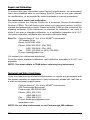
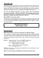
1
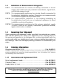
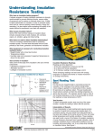
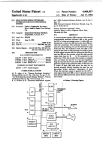
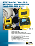
MEGOHMMETER ENGLISH User Manual 1015 Statement of Compliance Chauvin Arnoux®, Inc. d.b.a. AEMC® Instruments certifies that this instrument has been calibrated using standards and instruments traceable to international standards. We guarantee that at the time of shipping your instrument has met its published specifications. An NIST traceable certificate may be requested at the time of purchase, or obtained by returning the instrument to our repair and calibration facility, for a nominal charge. The recommended calibration interval for this instrument is 12 months and begins on the date of receipt by the customer. For recalibration, please use our calibration services. Refer to our repair and calibration section at www.aemc.com. Serial #: _________________________________ Catalog #: 1403.01 Model #: 1015 Please fill in the appropriate date as indicated: Date Received: __________________________________ Date Calibration Due: ________________________ Chauvin Arnoux®, Inc. d.b.a AEMC® Instruments www.aemc.com Table of Contents 1.INTRODUCTION................................................................................ 3 1.1 1.2 1.3 1.4 International Electrical Symbols.................................................3 Definition of Measurement Categories......................................4 Receiving Your Shipment...........................................................4 Ordering Information..................................................................4 1.4.1 Accessories and Replacement Parts.............................4 2. PRODUCT FEATURES....................................................................... 5 2.1 Description.................................................................................5 2.2 Features.....................................................................................5 2.3 Control Features........................................................................6 3.SPECIFICATIONS............................................................................. 7 3.1 Electrical Specifications.............................................................7 3.2 General Specifications...............................................................8 3.3 Safety Specifications.................................................................8 4.OPERATION..................................................................................... 9 4.1 Safety Check (Voltage Test)......................................................9 4.2 Insulation Resistance Testing (MΩ Range)...............................9 4.2.1 Test Voltage...................................................................9 4.2.2 Spot Testing.................................................................10 4.2.3 Ratio Testing................................................................10 4.2.4 Tips For Successful Insulation Resistance Testing.......... 11 4.2.5 Insulation Measurement - Connections....................... 11 4.2.6 Insulation Resistance Measurements on Motors.........14 4.3 Continuity.................................................................................15 Measurements.........................................................................15 4.4 Resistance Measurements......................................................15 5.MAINTENANCE.............................................................................. 16 5.1Maintenance............................................................................16 5.1.1 Battery Test..................................................................16 5.1.2 Battery and Fuse Replacement...................................17 5.1.3 Cleaning.......................................................................17 Repair and Calibration.....................................................................18 Technical and Sales Assistance.......................................................18 Limited Warranty..............................................................................19 Warranty Repairs.............................................................................19 CHAPTER 1 INTRODUCTION WARNING These safety warnings are provided to ensure the safety of personnel and proper operation of the instrument. • Read this instruction manual completely and follow all the safety information before attempting to use or service this instrument. • Safety is the responsibility of the operator! • Tests are to be carried out only on dead circuits! Check for live circuits before making resistance measurements (safety check). • Always make connections from the instrument to the circuit under test. • These megohmmeters are sources of high voltage, as is the sample connected to them. All persons performing or assisting in the tests must follow all safety precautions to prevent electrical shock to themselves and to others. • AEMC considers the use of rubber gloves to be an excellent safety practice even if the equipment is properly operated and correctly grounded. • When testing capacitance samples, make sure that they have been properly discharged and that they are safe to touch. Dielectric insulation samples should be short-circuited for at least five times the amount of time they were energized. • Never open the back of the instrument while connected to any circuit or input. 1.1 International Electrical Symbols This symbol signifies that the instrument is protected by double or reinforced insulation. This symbol on the instrument indicates a WARNING and that the operator must refer to the user manual for instructions before operating the instrument. In this manual, the symbol preceding instructions indicates that if the instructions are not followed, bodily injury, installation/sample and product damage may result. Risk of electric shock. The voltage at the parts marked with this symbol may be dangerous. In conformity with WEEE 2002/96/EC Megohmmeter Model 1015 3 1.2 Definition of Measurement Categories CAT I: For measurements on circuits not directly connected to the AC supply wall outlet such as protected secondaries, signal level, and limited energy circuits. CAT II: For measurements performed on circuits directly connected to the electrical distribution system. Examples are measurements on household appliances or portable tools. CAT III: For measurements performed in the building installation at the distribution level such as on hardwired equipment in fixed installation and circuit breakers. CAT IV: For measurements performed at the primary electrical supply (<1000V) such as on primary overcurrent protection devices, ripple control units, or meters. 1.3 Receiving Your Shipment Upon receiving your shipment, make sure that the contents are consistent with the packing list. Notify your distributor of any missing items. If the equipment appears to be damaged, file a claim immediately with the carrier and notify your distributor at once, giving a detailed description of any damage. Save the damaged packing container to substantiate your claim. 1.4 Ordering Information Megohmmeter Model 1015.................................................. Cat. #1403.01 Includes a carrying case, shockproof rubber housing, set of black and red leads, black test probe, red alligator clip, spare fuse (inside megohmmeter), four 1.5V alkaline “AA” batteries (not installed), and a user manual. 1.4.1 Accessories and Replacement Parts Set of replacement leads...................................................... Cat. #2119.01 Carrying Case...................................................................... Cat. #2118.40 Fuses, set of 5, 1.6A............................................................. Cat. #2970.22 Order Accessories and Replacement Parts Directly Online Check our Storefront at www.aemc.com for availability 4 Megohmmeter Model 1015 CHAPTER 2 PRODUCT FEATURES 2.1Description The Megohmmeter Model 1015 is an analog instrument with four easy-toread scales. The MΩ scale is an easy-to-read log scale graduated from 0.1 to 1000MΩ (yellow background) at 500V and 1000V. The Ω scale is linear with a range from 0 to 10Ω (white background). To use the 0 to 1000Ω scale, take the reading on the 0 to 10Ω range and multiply the reading by 100. The AC voltage scale is linear with a range of 0 to 600VAC (white background). Continuity tests are done with a test current of 200mA. The colored battery scale has a range of green for a good battery and a range of red or lower for a defective battery. A built-in battery tester is provided by simply pressing the yellow push button when the selector switch is in the OFF position. Voltmeter (safety check) with a range of 0 to 600VAC is standard and works when the selector switch is in the 500V position or the 1000V position. 2.2Features • • • • • • • • • • Measures insulation at 1000V 0 to 1000Ω resistance range Push button for battery check Designed for harsh environments: offshore, mining, heavy-duty field, industrial, commercial electrical and military use 0 to 10Ω+ and 0 to 10Ω- continuity ranges Continuity 200mA test current Small and lightweight Large, direct-reading, colored scale 600V test voltage range (safety check) Yellow non-slip shockproof case Megohmmeter Model 1015 5 2.3 Control Features 1 2 3 7 6 – 4 5 Figure 2 1. Line (–) terminal 2. Earth/Ground (+) terminal 3. Mechanical zero adjustment screws 4. 4-position rotary switch 5. Protective rubber housing 6. Push-to-test button 7. Battery check and indication display 6 Megohmmeter Model 1015 CHAPTER 3 SPECIFICATIONS 3.1 Electrical Specifications INSULATION TESTS DC Test Voltage:500 V and 1000 V Megohm Range: 0.1 to 1000 MΩ Short Circuit Current: ≤ 6 mA Accuracy: ±5% of reading Discharging Time (Auto): 1s/µF CONTINUITY TESTS Range: 0 to 10Ω-; 0 to 10Ω+ Short Circuit Current: ≥ 200 mA Open Circuit Voltage: 4.5 to 6.5V Accuracy: ±3% full scale RESISTANCE TESTS Range: 0 to 1000Ω Short Circuit Current: ≥ 2 mA Open Circuit Voltage: 4.5 to 6.5V Accuracy: ±3% full scale VOLTAGE TESTS (Safety Check) Voltage Range: 0 to 600VAC Frequency: 45 to 400Hz Accuracy: 3% of full scale Input Impedance: 300kΩ Megohmmeter Model 1015 7 3.2 General Specifications Power Supply: Four 1.5 V AA batteries Dielectric Test: 6000V, 50/60 Hz, 1 minute Meter Movement: Rugged taut band suspension Dimensions: 6.6 x 4.2 x 2.2" (167 x 106 x 55mm) Weight: 1.45 lbs (650 g) Operating Temperature Range: 14° to 131°F (-10° to 55°C), 20-80% RH Storage Range: -40° to 158°F (-40° to 70°C), 10-90% RH Terminals: “-” Line (black); “+” earth (red); accepts 4mm banana plugs Reference Conditions: 63° to 73°F (17° to 23°C), 45-55% RH; Supply Voltage: 5.3 to 5.7V; Voltage Frequency: 45 to 65Hz; Electric Field: <1V/M; Magnetic Field: <40A/M; Position: Horizontal ± 5°. 3.3 Safety Specifications IEC 1010-1: Safety requirements for electrical equipment for measurement, control and laboratory use VDE 0413-1: Insulation testers VDE 0413-4: Ohmmeters VDE 0100: Specifications for the creation of high current installations of nominal voltage less than 1000V IEC 801: Electromagnetic compatibility for measurement and control equipment in industrial processes Part 2: Sections relating to electrostatic discharges Part 3: Sections relating to radiated electric fields Part 4: Sections relating to electrostatic discharges Part 5: Sections relating to electric shocks IEC 68.2.6: Vibrations IEC 68.2.27: Shocks IEC 68.2.29: Shakes IEC 68.2.31: Bumps IEC 68.2.32: Free fall UL 94: Self-extinguishing capability Specifications are subject to change at any time without notice 8 Megohmmeter Model 1015 CHAPTER 4 OPERATION 4.1 Safety Check (Voltage Test) WARNING: MAKE SURE THE JACKS ARE FIRMLY INSERTED INTO THE TOP OF THE MEGOHMMETER PRIOR TO PERFORMING ANY ELECTRICAL TESTS! Before measuring insulation resistance, confirm that the sample is fully discharged (particularly in dielectric and capacitance samples), and that the sample is not connected to an energized circuit. To perform the voltage test: • Set the range selection to MΩ 500V or MΩ 1000V • Connect and read on the voltage scale (600VAC max) You do not need to press the yellow button to measure voltage. NOTE: If measuring voltage on a DC circuit, the pointer will deflect but the measurement may be inaccurate. 4.2 Insulation Resistance Testing (MΩ Range) After checking for a live circuit (see Safety Check above), connect the megohmmeter. Several connection examples are illustrated in Figures 3 through 10. 4.2.1 Test Voltage No published standard tells which voltage to choose for any given winding. However, published recommendations could be summarized as follows: Rated Voltage of Motor Below 115 115 230 460 Megohmmeter Model 1015 Test Voltage 250V 250V or 500V 500V 500V or 1000V 9 4.2.2 Spot Testing As a general rule in spot testing, test voltage should be applied until no variation in reading is noted for 15 seconds, or applied for a fixed 60 seconds. What minimum value should be measured? The IEEE standard No. 43-1974 states that it is impossible to specify the value of insulation resistance at which a winding will fail electrically, but on motors, minimum readings generally stated are: Rated Voltage 250 or less 460 R Minimum 2MΩ 2MΩ There is no fixed figure for determining what is good and bad in resistance readings, but a good guide would be 1 megohm for every one hundred applied operating volts, as a minimum figure. This applies to motors and transformers. When the insulation resistance gets this low, an electrical breakdown can be expected at any time, and rewinding or replacing should be considered. It is not unusual for a winding to be 10 to 100 times the recommended minimum value (IEEE Std. #43-1974: Recommended Practice for Testing Insulation Resistance of Rotating Machinery), but this varies with temperature and humidity. 4.2.3 Ratio Testing In time resistance reading (Dielectric Absorption Ratio), readings are taken at 30 and 60 seconds to obtain the dielectric absorption ratio. Insulation resistance @ 60s Insulation resistance @ 30s = Dielectric Absorption Ratio (DAR) This test is useful to increase the accuracy of spot testing. In general, a ratio of 1.25:2 or better should be required. A ratio below this indicates that repair is probably needed. Remember, a DC insulation test may be used for acceptance testing, but is more commonly used to check the gradual deterioration of equipment over its life. Consult your equipment manufacturer for specific test or test voltage if not known. Insulation resistance decreases with moisture, temperature and age and should be recorded over time at a given temperature and corrected. 10 Megohmmeter Model 1015 4.2.4 Tips For Successful Insulation Resistance Testing • Check with the equipment manufacturer for factory insulation resistance readings. • Do not rely on insulation resistance testing alone as proof of winding conditions. • Do not expect the same value for all parts of all machines. • Observe consistent test time duration, recognizing that total current through insulation under test will vary with time. • Correct all readings properly to a standard reference temperature (see IEEE Std. #43-1974, Temperature Correction Curve). • Know what you are testing. Isolate the piece of equipment from other circuitry. • Watch trends rather than relying on single “spot” readings. 4.2.5 Insulation Measurement - Connections Figure 3 shows the connections to measure the insulation of one conductor to the other conductors. The cable should be disconnected at both ends to avoid leakage through switchboards and panels. Conductor Under Test Cable Insulation - + 5 10 1 0.5 0.1 MΩ 0 2 1 100 3 200 4 50 10 0 5 300 6 400 7 500 8 9 500 60 0V 0 - ! Battery Check 600V 10 00 10 + 6 OFF MΩ - 500 V MΩ - 1000 V 1000 Ω 10 Ω + 10 Ω − AEMC I N S T R U M E N TS MEGOHMMETER MODEL 1015 Figure 3 Megohmmeter Model 1015 11 Figures 4 and 5 show the connections for testing insulation from a supply conductor to ground (motor frame). Conductor Under Test Cable Insulation - + 5 10 1 0.5 0.1 MΩ 100 50 10 0 5 4 3 2 1 0 6 300 200 7 400 500 8 9 500 60 0V 0 - ! 600V 10 00 10 + 6 Battery Check MΩ - 500 V OFF MΩ - 1000 V 1000 Ω 10 Ω + 10 Ω − MEGOHMMETER AEMC MODEL 1015 IN S T R U M E N TS Figure 4 Conductor Under Test Cable Insulation - + 5 10 1 0.5 0.1 MΩ 0 2 1 100 3 200 4 50 10 0 5 300 6 400 7 500 8 9 500 60 0V 0 - ! Battery Check 600V 10 00 10 + 6 OFF MΩ - 500 V MΩ - 1000 V 1000 Ω 10 Ω + 10 Ω − AEMC IN ST R U MEN TS MEGOHMMETER MODEL 1015 Figure 5 12 Megohmmeter Model 1015 Figure 6 shows the connections to a transformer (lighting or distribution). Tested Winding Make sure that the switches and/ or circuit breakers on both sides are open. Check the high voltage winding to ground, low voltage to ground, and the resistance between them with no winding grounded. Transformer Grounding Lug - + 5 10 1 0.5 0.1 MΩ 0 2 1 100 3 200 4 50 10 0 5 300 6 400 7 500 8 9 500 60 0V 0 - ! Battery Check 600V 10 00 10 + 6 OFF MΩ - 500 V MΩ - 1000 V 1000 Ω 10 Ω + 10 Ω − AEMC IN S TR U M E N TS Jumpers MEGOHMMETER MODEL 1015 Figure 6 ~ ~ ~ ~ ~ ~ - Figure 7 shows the connections for measuring the insulation of a threephase line to ground by connecting the jumpers between phases. + 5 10 1 0.5 0.1 MΩ 0 2 1 100 3 200 4 50 10 0 5 300 6 400 7 500 8 9 500 60 0V 0 - ! Battery Check 600V 10 00 10 + 6 OFF MΩ - 500 V MΩ - 1000 V 1000 Ω 10 Ω + 10 Ω − AEMC IN STRUMENTS MEGOHMMETER MODEL 1015 Figure 7 Megohmmeter Model 1015 This gives a reading of all conductors at once. If a load such as a motor, heater, etc., is attached to the other end of the line, it will read the load resistance to ground at the same time. By removing the jumpers, readings can be made between the individual conductors and ground. 13 4.2.6 Insulation Resistance Measurements on Motors Figure 8 shows reading the resistance to ground of a three-phase motor winding. Since the three-phase motors are internally connected, it is only necessary to connect one lead to the motor lead and the other lead to the motor frame as shown. - + 5 10 1 0.5 0.1 MΩ 0 2 1 100 3 200 4 50 10 0 5 300 6 400 7 500 8 9 500 60 0V 0 - ! Battery Check 600V 10 00 10 + 6 OFF MΩ - 500 V MΩ - 1000 V 1000 Ω 10 Ω + 10 Ω − AEMC I N STR U M EN TS MEGOHMMETER MODEL 1015 Figure 8 Figure 9 shows the windings of a three-phase motor separated. Sometimes this can be done at the lead terminals, while other times the end bells must be removed to get at the lead wires of the coils. By connecting the megohmmeter as shown, the phase insulation resistance value can now be determined. Read between phases “A” and “B”, then “B” and “C”, then “C” and “A”. 14 C A - B + 1 0.5 0.1 MΩ 5 10 0 2 1 100 3 200 4 50 10 0 5 300 6 400 7 500 8 9 500 60 0V 0 - ! Battery Check 600V 10 00 10 + 6 OFF MΩ - 500 V MΩ - 1000 V 1000 Ω 10 Ω + 10 Ω − AEMC INSTRUMENTS MEGOHMMETER MODEL 1015 Figure 9 Megohmmeter Model 1015 Figure 10 shows connections for testing insulation from a supply conductor in a switchbox to ground (motor frame). An identical test may be carried out from the motor starter. Motor Side of Switch: Connection to One Leg Starter In 4.3Continuity Measurements Once it has been verified that no voltage is present, the continuity check may be performed. • Set the switch to the 10Ω+ position. The measurement is done automatically; you do not need to press the yellow button. Grounded Motor Frame - + 5 10 1 0.5 0.1 MΩ 0 2 1 100 3 200 4 50 10 0 5 300 6 400 7 500 8 9 500 60 0V 0 - ! Battery Check 600V 10 00 10 + 6 OFF MΩ - 500 V MΩ - 1000 V 1000 Ω 10 Ω + 10 Ω − AEMC I N S T R U M E N TS • Read the value on the white scale 0 to 10Ω. MEGOHMMETER MODEL 1015 Figure 10 • Set the switch to the 10Ω– position and make sure that the needle of the instrument reads the same value. If the second value is different from the preceding one, add up the two readings and divide by two. The reason for taking two different readings is to comply with the international standard VDE 0413-4. If your work does not require you to conform to this standard, only one measurement is necessary. • Return to “OFF” after use. NOTE: For better measurement accuracy on the 10Ω+ and the 10Ω– ranges, measure the resistance of the leads by short-circuiting them, then subtract this value from the measured values. 4.4 Resistance Measurements • Set the switch to the 1000Ω position. The measurement is done automatically; you do not need to press the yellow button. • Read the value on the white scale 0 to 10Ω, then multiply the reading by 100 to get the actual value measured. • Return to “OFF” after use. Megohmmeter Model 1015 15 CHAPTER 5 MAINTENANCE 5.1Maintenance WARNING: • For maintenance use only specified replacement parts. • To avoid electrical shock, do not attempt to perform any servicing unless you are qualified to do so. • To avoid electrical shock and/or damage to the instrument, do not get water or other foreign agents into the case. Turn the instrument OFF and disconnect the unit from all the circuits before opening the case. 5.1.1 Battery Test Check that the batteries are in good working condition prior to using the instrument. With the switch in the OFF position, press the yellow button: • The batteries are good if the needle is in the green zone. • The batteries need replacement if the needle is in the red zone or lower. The average battery life is: • 1000 insulation measurements of 10 seconds on the MΩ -500V range for R = 500kΩ. • 200 insulation measurements of 10 seconds on the MΩ -1000V range for R = 1MΩ. • 1500 continuity measurements of 10 seconds on the 10Ω range. MΩ 5 10 1 0.5 0.1 0 2 1 100 3 200 4 50 10 0 5 300 6 400 7 500 8 9 500 60 0V 0 - ! 600V 10 00 10 + 6 RED zone or below: Battery needs to be replaced GREEN zone: Battery is good NOTE: The instrument will operate correctly with a battery voltage range of 4.5 to 6.5V. 16 Megohmmeter Model 1015 5.1.2 Battery and Fuse Replacement WARNING: Make sure that no terminals are connected and that the switch is in the OFF position before opening the back of the instrument. • Remove the yellow shockproof housing. • Remove the two screws from the back of the instrument (Fig. 11). • Remove the back cover. • Replace the fuse or batteries. NOTE: There is a spare fuse installed in the back cover. • Reverse the above procedure to install the back cover and the shock proof housing. • To close the back stand flush with the back cover, apply light pressure at Point A in Fig. 11. Cover screws 1.6 A fuse Point A + + + + 1.5 V batteries LR6 Figure 11 5.1.3Cleaning • Clean the body of the instrument with a cloth lightly moistened with soapy water. • Wipe clean with a cloth moistened with clean water and dry. • Do not use solvent. Megohmmeter Model 1015 17 Repair and Calibration To ensure that your instrument meets factory specifications, we recommend that it be scheduled back to our factory Service Center at one-year intervals for recalibration, or as required by other standards or internal procedures. For instrument repair and calibration: You must contact our Service Center for a Customer Service Authorization Number (CSA#). This will ensure that when your instrument arrives, it will be tracked and processed promptly. Please write the CSA# on the outside of the shipping container. If the instrument is returned for calibration, we need to know if you want a standard calibration, or a calibration traceable to N.I.S.T. (Includes calibration certificate plus recorded calibration data). Ship To: Chauvin Arnoux®, Inc. d.b.a. AEMC® Instruments 15 Faraday Drive Dover, NH 03820 USA Phone:(800) 945-2362 (Ext. 360) (603) 749-6434 (Ext. 360) Fax: (603) 742-2346 or (603) 749-6309 E-mail:[email protected] (Or contact your authorized distributor) Costs for repair, standard calibration, and calibration traceable to N.I.S.T. are available. NOTE: You must obtain a CSA# before returning any instrument. Technical and Sales Assistance If you are experiencing any technical problems, or require any assistance with the proper operation or application of your instrument, please call, mail, fax or e-mail our technical support team: Chauvin Arnoux®, Inc. d.b.a. AEMC® Instruments 200 Foxborough Boulevard Foxborough, MA 02035 USA Phone:(800) 343-1391 (508) 698-2115 Fax: (508) 698-2118 E-mail:[email protected] www.aemc.com NOTE: Do not ship Instruments to our Foxborough, MA address. 18 Megohmmeter Model 1015 Limited Warranty The Model 1015 is warranted to the owner for a period of one year from the date of original purchase against defects in manufacture. This limited warranty is given by AEMC® Instruments, not by the distributor from whom it was purchased. This warranty is void if the unit has been tampered with, abused or if the defect is related to service not performed by AEMC® Instruments. For full and detailed warranty coverage, please read the Warranty Coverage Information, which is attached to the Warranty Registration Card (if enclosed) or is available at www.aemc.com. Please keep the Warranty Coverage Information with your records. What AEMC® Instruments will do: If a malfunction occurs within the one-year period, you may return the instrument to us for repair, provided we have your warranty registration information on file or a proof of purchase. AEMC® Instruments will, at its option, repair or replace the faulty material. REGISTER ONLINE AT: www.aemc.com Warranty Repairs What you must do to return an Instrument for Warranty Repair: First, request a Customer Service Authorization Number (CSA#) by phone or by fax from our Service Department (see address below), then return the instrument along with the signed CSA Form. Please write the CSA# on the outside of the shipping container. Return the instrument, postage or shipment pre-paid to: Ship To: Chauvin Arnoux®, Inc. d.b.a. AEMC® Instruments 15 Faraday Drive • Dover, NH 03820 USA Phone:(800) 945-2362 (Ext. 360) (603) 749-6434 (Ext. 360) Fax: (603) 742-2346 or (603) 749-6309 E-mail:[email protected] Caution: To protect yourself against in-transit loss, we recommend you insure your returned material. NOTE: You must obtain a CSA# before returning any instrument. Megohmmeter Model 1015 19 Notes: 02/13 99-MAN 100089 v9 Chauvin Arnoux®, Inc. d.b.a. AEMC® Instruments 15 Faraday Drive • Dover, NH 03820 USA • Phone: (603) 749-6434 • Fax: (603) 742-2346 www.aemc.com