1
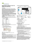
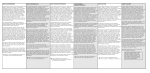
EE1941/EN1941/EN1941-60 One-Way Binary
RF Module
Installation and Operation Manual
1 Overview
EchoStream RF modules are designed to be easily interfaced with your
electronic remote application controller (RAC). RF modules allow the
assimilation of any user-specific application into an EchoStream system.
Once integrated with existing products, RF modules provide you with
complete EchoStream functionality.
One-way binary RF modules are end-devices that use a logic-level
connection to interface with your RAC. E*1941 one-way binary RF modules
can be used in either one-way or two-way EchoStream systems.
2 One-Way Binary RF Module Components
The E*1941 is a universal one-way binary RF module with two alarm input
pins, allowing the use of dual inputs. Input one is the primary alarm, bit 0;
input two is the secondary alarm, bit 1.
There are two models in the E*1941 product family.
• The EN1941 and EN1941-60, for 900 MHz applications in North
America, New Zealand, and Australia.
• The EE1941, for 868 MHz applications in Europe.
A
B
C
D
Figure 1 One-Way System Components
E
F
G
Note: For UL 2560 installations, refer to the EN6080 Area Control Gateway
H
Installation Instructions or EN6040-T Network Coordinator Installation Instructions.
1.1 Maximum Number of Repeaters for a UL 2560
Installation
To achieve the 99.99% alarm message reliability required for UL 2560
compliance, system installations must operate within the following limits for
end device and repeater counts.
End Devices
Maximum
Repeaters
150
397
250
386
350
375
500
360
1000
313
2000
238
3000
184
1.2 Inovonics Wireless Contact Information
For product and installation videos visit us at
www.inovonics.com/videos or use the QR
code below.
K
L
M
I
N
J
O
Figure 2 One-Way Binary RF Module Components
A Board stabilization hole. B Reserved
C Reserved
D Secondary alarm
E Power
F Ground
G Primary alarm
H LED contacts
I Tamper input
J Reset input
K Frequency band
selection pins
L N/O selection pins
M Mounting hole
N On-board antenna O Board stabilization
hole
A
B
C
D
E
F
G
K
L
M
I
N
J
O
H
Figure 3 EE1941 One-Way Binary RF Module Components
If you have any problems with this procedure, contact Inovonics Wireless
technical services:
• E-mail: [email protected].
• Phone: (800) 782-2709; (303) 939-9336.
1.3 Installation Notes
• These products are designed to be installed and maintained by
professional security technicians.
• Products are intended for indoor use.
• Manually test all products weekly.
2.16.15 06287G © Inovonics, 2015 - www.inovonics.com
A Board stabilization hole. B Reserved
C Reserved
D Secondary alarm
E Power
F Ground
G Primary alarm
H LED contacts
I Tamper input
J Reset input
K ES selection pins
L N/O selection pins
M Mounting hole
N On-board antenna O Board stabilization
hole
Frequency band selection pins (EN1941 and EN1941-60 only) Place a
jumper to select the frequency band for your geographic area.
• Place the jumper on the left two pins to select 915-928 MHz for
Australia.
• Place the jumper on the right two pins to select 921-928 MHz for New
Zealand.
• Leave the jumper off the pins to select 902-928 MHz for North
America.
ES selection pins (EE1941 only) To enable compatibility with ES products,
place a selection jumper on the ES selection pins; if no ES products are
used in your system, remove the selection jumper.
N/O selection pins Place a jumper to select normally open inputs; remove
the jumper to select normally closed.
Note: The E*1941 is shipped with the jumper unattached. With the jumper
unattached, the E*1941 defaults to normally closed.
Secondary alarm Connects a secondary end-device to provide RF alarm
data for any user-specific application.
Primary alarm Connects a primary end-device to provide RF alarm data for
any user-specific application.
Tamper input Connects a tamper input to send a message when userspecific end-device is tampered with.
Reset input Connects a reset input to reset the one-way binary RF module
after a frequency band selection change or N/O - N/C selection change,
and to initiate an RF transmission.
Power Connect power cabling to an external power supply of 2.4 to 5.5
volts.
Ground Connects to ground.
Mounting hole Used to mount the one-way binary RF module to the userspecific product. The mounting hole should only be used with a nylon
standoff, never metal.
LED contacts Use to control an LED switch. Not designed to drive LED
power.
Board stabilization holes Used to mount and stabilize the board. The board
stabilization holes should only be used with non-metal standoffs.
3 One-Way Binary RF Module Dimensions
Clear transmit
region in front
and back of
antenna
RF
module
.515” to
Center of
Hole
.156”
Diameter
.090” to
Center
of First
Pin
5 Installation
A Connecting the One-Way Binary RF Module
B One-way binary RF modules are designed to be easily interfaced with
your electronic remote application controller, however integration must
conform to the following:
C The RF module must only be connected at the eight pin header or eight
pin plated through-holes.
D All cables and wires must be routed away from the component side of
the RF module.
E The integrated antenna must not be tampered with; no connection to an
alternate antenna is provided.
F The application module must not include an integrated secondary
collocated radio module.
G The one-way binary RF module antenna should be placed so that it is
facing away, or otherwise isolated from, your device’s ground plane.
H Components that are sensitive to RF transmission, such as high gain
circuits, should be isolated from the antenna to prevent interference.
I One-way binary RF modules should not be mounted on metal surfaces
or inside metal enclosures. They should also not be mounted where
sheet metal ductwork, wire mesh screens, etc. might block
transmissions.
J The RF module should be integrated so the antenna is unobstructed by
the end user’s PCB, batteries, or any other conductive material.
.335” to
Center
of Hole
1.3”
Pitch:
2.54mm.
.385” to
Center of
First Pin
End user
application
printed circuit
board
Figure 5 The RF module should be integrated so the antenna is
unobstructed
6 One-Way Binary RF Module Requirements
.5”
2.525”
Figure 4 E*1941 One-Way Binary RF Module Dimensions
4 One-Way Binary RF Module Connections and
Output Jumpers
Connection
Output
Jumper N/O
Output
Jumper N/C
Primary
Alarm
Open
Alarm Clear
Alarm
Ground
Alarm
Alarm Clear
Secondary
Alarm
Open
Alarm Clear
Alarm
Ground
Alarm
Alarm Clear
Open
Alarm
Alarm
Ground
Alarm Clear
Alarm Clear
Tamper
Reset
Open for normal operation; connect to the ground and
release for a board reset.
2.16.15 06287G © Inovonics, 2015 - www.inovonics.com
6.1 Power Requirements
The E*1941 has an on-board voltage regulator. Connect power cabling to
an external power supply (Vcc) of 2.4 to 5.5 volts. Voltage must be
sustained at 2.4 volts or above and supply 100 milliamps during the
transmit cycle.
6.2 EN1941 and EN1941-60
Assuming check-in messages every 3 minutes and infrequent alarm
messages (one per day, on average), the average current draw is 32 uA.
Peak current draw while transmitting is less than 100 mA. One alarm/
restore cycle per hour results in about 5.3 uA increase in average current.
EN1941 transmitters send a check-in message every three minutes;
EN1941-60 transmitters send a check-in message every 60 minutes;
Note: For UL 2560 installations, transmitters must have a minimum checkin time of 60 minutes.
6.3 EE1941
Assuming check-in messages every 12 minutes and infrequent alarm
messages (one per day, on average), the average current draw is 15 uA.
Peak current draw while transmitting is less than 50 mA. One alarm/restore
cycle per hour results in about 5.3 uA increase in average current.
6.4 Low Battery Condition
The E*1941 measures battery voltage every three and a half hours, and,
when the battery measures 2.4 volts, a serial message is sent indicating a
low battery condition.
6.5 Temperature range
-40°C to +66°C, non-condensing
2
6.6 RF network compatibility
EchoStream Commercial Mesh Network
6.7 Input Requirements
Caution: Input levels must not exceed 3.3 V.
Open When an active source (open collector or dry contact) is used to drive
the alarm or tamper input, the voltage should be between 0.75xVcc and
Vcc. A passive input should have an impedance of greater than 5.1k ohm
between the input and ground.
Closed When an active source is used, the voltage should be less than
0.25xVcc. A passive input should have an impedance of less than 240
ohm.
6.8 LED Requirements
The LED output is an active output from the microprocessor, with a 1k
series resistor to limit current draw. Default state is low, and the LED pin is
pulled high during transmit.
7 Compliance Requirements
7.1 UL and cUL Requirements
The module holds a UL and cUL Recognized Component Mark and is
intended to be factory installed in another device, system or end-product.
The suitability of the module for use in a UL and/or cUL listed (certified)
device, system or end-product, is restricted as follows:
• The EN1941 was evaluated as a UL/cUL Recognized Component
compliant to selected requirements from UL639, ULC-S306-03,
UL1076, ULC/ORD-C1076 and UL1610 as specified in the Conditions
of Acceptability of the UL Report.
• The Supply Line Transient tests shall be added to the RAC UL
evaluation program if it is powered by an AC/DC adapter rather than a
low voltage battery.
• If intended use includes UL1610, UL1076 or UL639 installations, the
RAC shall be evaluated for Short Range RF Device tests.
• Compatible UL receivers (except for UL 2560) include EN4216MR,
EN4232MR and EN7285. Refer to the EN4216MR Installation and
Operation Manual, the EN4232MR Installation and Operation Manual
or the EN7285 Installation Instructions.
• The EN1941-60 is a UL2560 unlisted component.
• The compatible receivers for UL 2560 installations are the EN6080
area control gateway and EN6040-T network coordinator. Refer to the
EN6080 Area Control Gateway Installation Instructions and the
EN6080 Area Control Gateway User Manual, or the EN6040-T
Network Coordinator Installation Instructions.
• The compatible repeater for UL 2560 installations is the EN5040-20T.
• When selecting frequency band, only devices set for use in North
America are configured for UL and cUL installations.
• In a UL 2560 installation, the EN1941-60 one-way binary RF module
may be used with completed emergency call systems for assisted
living and independent living facilities
• For UL 2560 certified system installations, the following Inovonics
EchoStream devices are approved for installation within maximum
system configuration limits defined in section 1.1 of this document:
- EN6080 area control gateway or EN6040-T network coordinator.
- EN5040-20T high power repeater.
- End devices (transmitters) with a minimum 60-minute check-in
interval, as follows:
Fundamental devices which are subject to UL2560 certification
(pendant transmitters and OEM products using the Inovonics RF
module)
Supplemental devices which are not subject to UL2560 system
certification but which may be used within a UL2560 certified
system (e.g. universal transmitters and activity sensors)
• Users that have achieved certification and will install UL 2560 certified
systems are responsible for labeling all fundamental devices with the
UL 2560 system certification mark.
Prior to marketing the product, the integrator must complete and submit to
Inovonics a compliance review form and documentation, and, if requested,
a functional product sample for approval. If this is not possible, the
integrator must perform the testing themselves and submit proof to
Inovonics of compliance to Part 15 of the FCC Rules and Industry Canada
RSS-210.
At the end of this guide is an Inovonics compliance review form to be filled
out by the integrator.
The integrator is also responsible for properly labeling the product
containing the one-way binary RF module. Labels must be placed on the
outside of the product, and must include a statement indicating that the
product contains the module, along with the FCC and IC number.
Example 1 “Contains One-Way Binary RF Module
FCC ID: HCQ3B6OT9OEM; IC ID: 2309A-OT9OEM (EN1941-IC)”
Example 2 “Contains FCC ID: HCQ3B6OT9OEM; IC ID: 2309A-OT9OEM
(EN1941-IC)”
7.3 Television and Radio Interference
This equipment has been tested and found to comply with the limits for a
Class B digital device, pursuant to Part 15 of the FCC Rules. These limits
are designed to provide reasonable protection against harmful interference
in a residential installation. This equipment generates, uses and can
radiate radio frequency energy and, if not installed and used in accordance
with the instructions, may cause harmful interference to radio
communications. However, there is no guarantee that interference will not
occur in a particular installation. If this equipment does cause harmful
interference to radio or television reception, which can be determined by
turning the equipment off and on, the user is encouraged to try to correct
the interference by one or more of the following measures:
• Reorient or relocate the receiving antenna.
• Increase the separation between the equipment and receiver.
• Connect the equipment into an outlet on a circuit different from that to
which the receiver is connected.
• Consult the dealer or an experienced radio/TV technician for help.
8 FCC Part 15 and Industry Canada Compliance
This device complies with part 15 of the FCC Rules and Industry Canada
license-exempt RSS standard(s). Operation is subject to the following two
conditions: (1) this device may not cause interference, and (2) this device
must accept any interference, including interference that may cause
undesired operation of the device.
Le présent appareil est conforme aux CNR d'Industrie Canada applicables
aux appareils radio exempts de licence. L'exploitation est autorisée aux
deux conditions suivantes : (1) l'appareil ne doit pas produire de brouillage,
et (2) l'utilisateur de l'appareil doit accepter tout brouillage radioélectrique
subi, même si le brouillage est susceptible d'en compromettre le
fonctionnement.
8.1 CE Label Requirements for EE1941
Inovonics Wireless has received European Telecommunications Standards
Institute approval to market one-way binary RF modules, and they are
manufactured to be RoHS compliant. The integrator is responsible for
properly labeling the product containing the one-way binary RF module.
Labels must be placed on the outside of the product, and must include the
CE logo.
Caution: Changes or modifications not expressly approved by the party
responsible for compliance could void the user's authority to operate the
equipment.
9 US Patent Numbers
•
•
•
•
7,154,866.
7,554,932.
7,746,804.
Other patents pending.
7.2 FCC Requirements for the RF Module
The one-way binary RF module has received a Limited Modular Grant,
requiring Inovonics to retain control of the final installation to ensure
compliance to FCC/IC regulations. The integrator is responsible to test the
final installation to verify compliance to FCC/IC regulation for unintentional
emissions. Changes or modifications not expressly approved by the party
responsible for compliance could void the user's authority to operate the
equipment.
2.16.15 06287G © Inovonics, 2015 - www.inovonics.com
3
Inovonics One-Way Binary RF Module Compliance
Review Form
Please provide the following information for review of final installation to ensure compliance
with FCC/IC regulations:
Required materials from integrator
The following must also be attached for review with this form:
• A description of the final installation, with attached photographs, as necessary
•The unintentional radiator test report indicating compliance
Integrator information
First name:
Last name:
Phone number:
Email address:
Address:
Declaration of conformity to Inovonics’ installation instructions:
Submitted materials:
Authorized signature:
Submission date:
Inovonics contact information
Inovonics
ATTN: Product Management
397 South Taylor Ave.
Louisville, CO 80027
Phone: 303.939.9336
Toll-Free: 800.782.2709
Fax: 303.939.8977
[email protected]
2.16.15 06287G © Inovonics, 2015 - www.inovonics.com
4
Required materials from Inovonics
• The record of product sample review and test, as necessary
Inovonics approval
First name:
Last name:
Phone number:
Email address:
Approval status (pass, fail, samples required, compliance testing required, compliance test report
required):
Approval comments:
Submitted materials:
Returned materials:
Authorized signature:
2.16.15 06287G © Inovonics, 2015 - www.inovonics.com
Approval date:
5