1
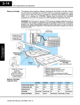
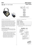
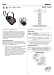
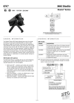
DL330/DL330P/DL340
CPU Specifications
In This Chapter. . . .
— Overview
— CPU Hardware Features
— CPU Specifications
— Selecting CPU Memory Options
— DL330/DL330P CPU Setup
— DL340 CPU Setup
— DL340 Port Setup
— Battery Backup
— Installing the CPU
— CPU Setup and System Functions
13
DL330/DL330P/DL340
Specifications
DL330/DL330P/DL340
CPU Specifications
DL330/DL330P/DL340
CPU Specifications
DL330/DL330P/DL340
Specifications
3--2
DL330/DL330P/DL340 CPU Specifications
Overview
The CPU is the heart of the control system. Almost all system operations are
controlled by the CPU, so it is important that it is set-up and installed correctly. This
chapter provides the information needed to understand:
S the differences between the different models of CPUs
S the different memory options
S the steps required to setup and install the CPU.
The DL330 modular CPU is capable of controlling 176 I/O points and has 3.7K words
of program storage. This CPU supports the RLL programing language and can save
programs internally to RAM or UVPROM. There is a built-in programming port that
directly supports the handheld programmer.
DL330 CPU
Features
DL330P CPU
Features
The DL330P modular CPU is capable of controlling 176 I/O points and has 3.7K
words program storage. This CPU supports the RLL PLUS programing language and
can save programs internally to RAM or UVPROM. RLL PLUS provides a structured
programming environment for Relay Ladder Logic through the addition of stage
logic. There is a built-in port that directly supports the handheld programmer.
DL340 CPU
Features
The DL340 modular CPU is capable of controlling 184 I/O points and has 3.7K words
program storage. This CPU supports the RLL programming language and can save
programs internally to RAM, UVPROM or EEPROM. There is a handheld
programming port and two built-in RS232C ports for PC programming, operator
interfaces, or networking. If you are using the DL340 in a DirectNET network, you
can use either port as a slave port and the bottom port as a master. The bottom port
has the additional capability of being configured as a slave on a Modbus® network.
CPU Hardware Features
CPU Status Indicators
RUN
ON
OFF
CPU is in RUN mode
CPU is in Program mode
BATT
ON
OFF
Memory backup voltage low
Memory backup voltage good
ON
OFF
CPU failure (Error detected when the
watchdog timer is not processed within
100ms. The run output from the power
supply will be turned off.)
CPU good
ON
OFF
CPU power good
CPU power failure
ON
CPU communication port
receiving data
CPU communication port
not receiving data
CPU
PWR
RX
OFF
TX
ON
OFF
CPU communication port
transmitting data
CPU communication port
not transmitting data
DL305 User Manual, Rev. D
CPU Slot
DL330
DL330P
RUN
RUN
BATT
BATT
CPU
CPU
LED
Indicators
Peripheral
Port
(HP, HPP, DCU,
UVPROM
Writer)
Network
Address
Mode
Switch
POWER
POWER
RS232C
Communication
Ports
--DirectSOFT
--DirectNET
--Operator
Interfaces
--Modbus®
DL340
PWR
RUN
PORT1
TX/RX
BATT
PORT2
TX/RX
CPU
DL330/DL330P/DL340 CPU Specifications
Feature
DL330
DL330P
DL340
Program memory (words)
3.7K
3.7K
3.7K
Scan time/K ladder (boolean)
8 ms
20 ms
.87 ms
Supports Overrides
No
No
Yes
RLL (Relay Ladder Logic) Programming
Yes
Yes
Yes
RLL PLUS Programming
No
Yes
No
Handheld programmer with cassette tape interface
Yes
Yes
Yes
DirectSOFT programming for Windowst
Yes
Yes
Yes
Built-in communication ports (RS232C / DirectNET)
No
No
Yes
CMOS RAM
Yes
Yes
Yes
UVPROM
Optional
Optional
Optional
EEPROM
No
No
Optional
ASCII Basic modules
Yes
Yes
Yes
Networking modules
Yes
Yes
Yes
RS232C Data Communications Unit
Yes
Yes
Yes
RS422 Data Communications Unit
Yes
Yes
Yes
110/220 VAC
Yes
Yes
Yes
24 VDC (5 slot base only)
Yes
Yes
Yes
Local I/O
128
128
136
Local expansion I/O
176
176
184
Remote I/O
NA
NA
NA
Number of instructions available
61
65
61
Control relays
140
77
196
Shift register bits
128
uses CRs
128
Special relays (system defined)
12
11
20
None
128
None
Timer/Counters
64
64
64
Data registers
128
128
192
Analog input channels max.
112
112
128
Analog output channels max.
28
28
32
Internal diagnostics
Yes
Yes
Yes
Password security
Yes
Yes
Yes
Battery backup
Yes
Yes
Yes
DL330/DL330P/DL340
Specifications
CPU Specifications
3--3
Compatible with:
DL305 User Manual, Rev. D
DL330/DL330P/DL340
Specifications
Stages
(RLL PLUS only)
DL330/DL330P/DL340
CPU Specifications
Total I/O points using;
DL330/DL330P/DL340
CPU Specifications
Base Power Supply Available
DL330/DL330P/DL340 CPU Specifications
Selecting CPU Memory Options
Internal Retentive
Memory
In addition to different choices for program storage, you can also select some
memory areas to be retentive. Retentive memory retains its state after a power cycle
or a program to run transition occurs, as long as the memory backup battery is
functional. Non--retentive memory resets to a logical “0” after a power cycle or a
program to run transition occurs. You have to use dipswitch to select the retentive
memory options (the switches are discussed in the next section.)
The following table shows the how the types of memory are defined. Some types of
memory are automatically defined as retentive and other memory types can be
defined as retentive as necessary for your application. The types of memory
available depend on the type of CPU selected for your application.
Retentive Memory
Pre--defined
Application program
Yes
User defined
Stages (DL330P only)
Yes
Internal relays
Yes
Current count values
Yes (full range)
Shift register bits
Yes (full range)
Data registers
Yes (full range)
Password
Yes
External Program
Storage
All DL305 CPUs allow for program storage to be captured on external media such as
cassette tape, floppy disk and hard disk. Refer to the DL305 Handheld Programmer
manual for details on storing the CPU program to cassette tape. The DirectSOFT
manual provides details on storing the CPU program to floppy or hard disk.
Volatile and
Non-volatile
Memory
There are two types of memory storage available, volatile and non-volatile. Volatile
memory will retain your data as long as proper voltage is maintained to the storage
media. Non-volatile memory does not require power to retain data. The DL305
CPUs maintain the proper voltage either through the base power supply or the use of
the memory backup battery.
DL330/DL330P/DL340
Specifications
DL330/DL330P/DL340
CPU Specifications
DL330/DL330P/DL340
CPU Specifications
DL330/DL330P/DL340
Specifications
3--4
DL305 User Manual, Rev. D
DL330/DL330P/DL340 CPU Specifications
The type of program storage memory available to you depends on the CPU you are
using. All DL305 CPUs support application program storage to either CMOS RAM or
the optional UVPROM. The DL340 has the added option of supporting program
storage in EEPROM. The application program can be up to 3.7K words.
S CMOS RAM memory (Random Access Memory) is standard on all the
DL305 CPUs. It is a volatile memory which can be modified or changed
easily with a handheld programmer or PC programming software.
S UVPROM (Ultraviolet Programmable Read Only Memory) is optional for
all the DL305 CPUs. This type of memory is non--volatile and can only
be erased with an ultraviolet light source. The PROM Writer Unit
(D3--PWU) is used to copy your application program from the CPU’s
RAM to a UVPROM. If the UVPROM has a program to be changed, it
must be removed from the CPU and erased before another program can
be copied on the UVPROM.
S EEPROM (Electrically Erasable Programmable Read Only Memory) is
an option only on the DL340 CPU. This type of memory is non--volatile,
but can be electrically erased. The EEPROM can be electrically
reprogrammed without being removed from the CPU, and without the
use of a special external programming device.
DL330/DL330P/DL340
Specifications
WARNING: Be sure to use proper grounding techniques when touching
UVPROMS and EEPROMS. A static discharge from you may cause damage to
the PROM. If you do not have a ground strap, then ground yourself by
touching the controller chassis before you make contact with the PROM. Also
ensure that the surface where you place the PROM is properly grounded.
DL330/DL330P/DL340
CPU Specifications
Program Storage
Memory Types
(Internal)
3--5
DL330/DL330P/DL340
CPU Specifications
DL330/DL330P/DL340
Specifications
DL305 User Manual, Rev. D
DL330/DL330P/DL340
Specifications
3--6
DL330/DL330P/DL340 CPU Specifications
Storing Programs
on UVPROMs
The PROM Writer Unit is only compatible with DL305 CPUs and UVPROMs. It can
perform the following three functions:
S
Copy a program from the CPU’s RAM to a UVPROM
S
Copy a program from the UVPROM to the CPU’s RAM
S
Compare the program in the UVPROM with the CPU’s RAM
Operation
Selection Buttons
UVPROM
Socket
UVPROM
BLANK
WRITE
VERIFY
DL330/DL330P/DL340
Specifications
DL330/DL330P/DL340
CPU Specifications
DL330/DL330P/DL340
CPU Specifications
ERR
Socket Lever used to lock
down and release UVPROM
during write procedure
The LED for the selected function will turn off when completed (except for the error
reset function). If any error is encountered, one of the LEDs in the following table will
be on and the execution of the selected function will be stopped.
Function
Key
Operation
LED
Display
Remarks
Errors Flagged
Copies the content of WRITE
the CPU RAM into the
UVPROM
~WRITE
Automatic comparison Constant on indicates
is made after
a write failure.
checking and writing.
Copies the content of
the UVPROM into the
CPU RAM
WRITE
VERIFY
~WRITE
~VERIFY
Depress two keys at
the same time.
Comparison is made
after transferring.
To verify the content
of the UVPROM with
the CPU RAM
VERIFY
~VERIFY
Constant on indicates
an unmatched
address.
To check if the
UVPROM is blank.
BLANK
~BLANK
Constant on indicates
a non-blank address
is found.
Error reset
ERR
~ERR
Return to the initial
condition by pressing
this key if an error
condition is noted.
On indicates an error.
~CPU
Red
On indicates failure.
~PWR
Green
On indicates DC
power is within
tolerance.
Off indicates DC
power not within
tolerance.
DL305 User Manual, Rev. D
DL330/DL330P/DL340 CPU Specifications
The PROM Writer Unit connects directly to either a DL330, DL330P or DL340 CPU.
Use the following steps to connect the PROM Writer Unit:
1. Set the power supply source switch (on the back of the unit) to the
appropriate power source setting, (INT for using base power and EXT for
an external power source). The PROM Writer Unit can either use the local
CPU base power or use an external power source.
NOTE: If you are using the local CPU base power you will need to include
the Prom Writer Unit power consumption in your power budget. The power
budget is covered in Chapter 4.
DL330/DL330P/DL340
CPU Specifications
DL330/DL330P/DL340
Specifications
DL305 User Manual, Rev. D
DL330/DL330P/DL340
CPU Specifications
2. If using an external power source attach the supplied cable to the power
source socket on the back of the unit. The white wire should be connected
to +5VDC and the black wire should be connected to DC ground.
3. Turn off the power source to the base before attaching the PROM Writer
Unit.
4. Attach the PROM Writer Unit to the CPU. The connector on the back of the
unit will mate with the programming port (PRG) of the CPU. Tighten the
fixture screw to secure the two units together.
5. Apply power to the local CPU base and if necessary to the PROM Writer
Unit. Once the PWR LED is on it will take approximately 10 seconds for the
unit to initialize. During this time keystrokes will not be recognized.
Copying a Program The following steps explain how to copy a program from the CPU RAM to a
From the CPU RAM UVPROM:
1. Turn power on.
to a UVPROM
2. Raise the UVPROM socket lever.
3. Insert the UVPROM (notch up) in the socket and lower the lever.
4. Press the “WRITE” button. The following sequence of events will take
place:
S The WRITE LED will turn on then off.
S The BLANK LED will come on. (This notes the checking sequence to
ensure that the UVPROM is blank has started.)
S The BLANK LED will turn off and the WRITE LED will turn on.
S The WRITE LED will turn off and the VERIFY LED will turn on. (This
indicates that the write is complete. While the VERIFY LED is on, a
comparison between the UVPROM and the CPU RAM is being
made.)
S The VERIFY LED will turn off. (This indicates the end of the copying
function.)
S If an error has been detected, the ERR LED will come on. If this
happens press the “ERR” key to clear the error and the “WRITE” key
to repeat the procedure. If this does not correct the problem, repeat
the procedure using a different UVPROM.
5. Turn power off, raise the UVPROM socket lever and remove UVPROM.
DL330/DL330P/DL340
Specifications
Setting up the
PROM Writer Unit
3--7
DL330/DL330P/DL340
Specifications
3--8
DL330/DL330P/DL340 CPU Specifications
Copying a Program The following steps explain how to copy a program from the UVPROM to the CPU
From the UVPROM RAM:
1. Turn power on.
to the CPU RAM
2. Raise the UVPROM socket lever.
3. Insert the UVPROM (notch up) in the socket and lower the lever.
4. Simultaneously press “WRITE” and “VERIFY” buttons. The following
sequence of events will take place:
S The BLANK, WRITE and VERIFY LEDs will all come on
momentarily.
S The WRITE LED turns off.
S The VERIFY LED will stay on till the operation is completed.
S If an error has been detected, the ERR LED will come on. If this
happens, press the “ERR” key to clear the error and repeat step 4.
5. Turn power off, raise the UVPROM socket lever and remove UVPROM.
The following steps show how to compare a UVPROM program to the CPU RAM:
1. Turn power on.
2. Raise the UVPROM socket lever.
3. Insert the UVPROM (notch up) in the socket and lower the lever.
4. Press the “VERIFY” button. The following sequence of events will take
place:
S The VERIFY LED indicator will come on.
S If verification is successful, the VERIFY LED will go off.
S If there is an error in the comparison the VERIFY LED will remain
on.
5. Turn power off, raise the UVPROM socket lever and remove UVPROM.
Erasing a UVPROM UVPROMS can be erased through exposure to an ultraviolet light source. Make sure
that the window to the UVPROM is not covered so that it may receive full exposure to
the light source. A typical exposure would be: 12,000μ w/cm2 lamp @ 2.5 cm for
15--20 minutes.
DL330/DL330P/DL340
Specifications
DL330/DL330P/DL340
CPU Specifications
DL330/DL330P/DL340
CPU Specifications
Comparing a
Program From the
UVPROM to the
CPU RAM
DL305 User Manual, Rev. D
DL330/DL330P/DL340 CPU Specifications
3--9
Installing the
S
UVPROM Option in
the DL330 / DL330P
CPU
S
S
S
S
S
S
Disconnect the power from the base and
allow approximately 60 seconds for the
capacitor to discharge before removing
the CPU.
Disconnect the battery wires from the
CPU.
Remove the RAM chip from IC socket.
Align the UVPROM notch with the IC
socket notch on the CPU card.
Carefully insert the UVPROM in the IC
socket.
Set dip switch 2 and Jumpers 1 -- 3 for
UVPROM (ROM).
Reconnect the battery wires to CPU.
Memory
Type
Switch
RAM
UVPROM
(ROM)
JUMPER 1
DL330/DL330P/DL340
Specifications
DL330/DL330P CPU Setup
JUMPER 2
JUMPER 3
DIPSWITCH 2
(on)
(off)
ON
2
Dipswitch 1
(ON selects
power failure Dipswitch 2
(ON -- RAM
retention)
OFF -- UVPROM)
BATTERY
ROM
Jumper 1
RAM/UVPROM
Jumper 2
RAM
RAM
Jumper 3
Selecting Retentive The DL330 and DL330P have a dipswitch which can be used to turn on or off power
failure retention for specific relays and stages. (Some memory types are
Memory for the
automatically retentive.) The following diagram lists the range of retentive memory
DL330 / DL330P
for the memory types that are covered by the selection switch.
ON
BATTERY
ROM
RAM/UVPROM
ROM
DL330/DL330P
Networking
RAM
1 2
RAM
Internal relays in the DL330P range from
160 -- 277, only 200 -- 277 can be set retentive
or non--retentive.
Stages in the DL330P range from
SG000 to SG177, only SG000 to SG137 can
be set retentive or non--retentive.
Networking for the DL330 and DL330P is accomplished by using a DCU, (Data
Communications Unit, RS232C part number D3-232-DCU, RS422 part number
D3-422-DCU).
DL305 User Manual, Rev. D
DL330/DL330P/DL340
Specifications
Dipswitch 1 Internal relays in the DL330 range from
(on selects
160 -- 373, only 340 -- 373 can be set
power failure retentive or non--retentive.
retention)
DL330/DL330P/DL340
CPU Specifications
ROM
DL330/DL330P/DL340
CPU Specifications
1
DL330/DL330P/DL340
Specifications
3--10
DL330/DL330P/DL340 CPU Specifications
DL340 CPU Setup
Installing the
optional UVPROM
or EEPROM in the
DL340 CPU
Complete the following steps to install the optional memory.
1. Disconnect the power from the base and allow approximately 60 seconds
for the capacitor to discharge before removing the CPU.
2. Disconnect the battery wires from the CPU.
3. Align the UVPROM/EEPROM notch with the IC socket notch on the CPU.
4. Carefully insert the UVPROM/EEPROM into the IC socket.
5. Set dipswitch SW1, bit 1 and the short Jumpers N/C -- 4 for the option you
have installed.
6. Reconnect the battery wires to the CPU.
Memory
Type
Switch
RAM
SHORT PIN
JUMPERS
DL330/DL330P/DL340
CPU Specifications
DL330/DL330P/DL340
CPU Specifications
1
DIPSWITCH
SW1 -- Bit 1
2
EEPROM
3
4
...
1
2
3
4
UVPROM
(ROM)
EEPROM
(WRITE PROTECTED)
...
1
2
3
4
...
1
ON
ON
ON
ON
OFF
OFF
OFF
OFF
N/C 2 3 4
N/C 2 3 4
N/C 2 3 4
DL330/DL330P/DL340
Specifications
3
4
N/C 2 3 4
N/C 2
DL305 User Manual, Rev. D
2
3
4
...
DL330/DL330P/DL340 CPU Specifications
3--11
Retentive
Memory
Switch
ON
DIPSWITCH
SW1 -- Bit 2
OFF
1 2 3 4 5 6 7 8
Non--Retentive
Memory
ON
1 2 3 4 5 6 7 8
DL330/DL330P/DL340
Specifications
Selecting Retentive The DL340 uses the same dipswitch for selecting memory retention as was used for
memory type selection. Dipswitch SW1, bit 2 is used to set memory retention for the
Memory for the
ranges of internal relays shown in the following diagram.
DL340
OFF
Internal relays in the DL340 range from 160 to
373 and 1000 to 1067, only 340 -- 373 can be set
retentive or non--retentive.
DL330/DL330P/DL340
CPU Specifications
DL330/DL330P/DL340
CPU Specifications
DL330/DL330P/DL340
Specifications
DL305 User Manual, Rev. D
DL330/DL330P/DL340
Specifications
3--12
DL340 Port Setup
DL340 Baud Rate
Selection
The following chart shows how to configure the baud rate for Port 1 (RS232C) of the
DL340 using dipswitch SW1, switches 3, 4 and 5. Port 2 baud rate is set by using a
programming device to enter the baud rate in address R773 (in BCD or HEX).
Port 1
Port 2
Sample Setup Ladder Logic
Port 1 300 Baud
Port 1 4800 Baud
ON 1 2 3 4 5 6 7 8
ON 1 2 3 4 5 6 7 8
Baud
R773
C374
DSTR
300
1
OFF
OFF
K006
Port 1 600 Baud
Port 1 9600 Baud
600
2
1st scan only.
ON 1 2 3 4 5 6 7 8
ON 1 2 3 4 5 6 7 8
Set baud rate to 9600
1200
3
DOUT1
SW1
2400
4
OFF
OFF
R773
Port 1 1200 Baud
Port 1 19200 Baud
4800
5
1st scan only.
ON 1 2 3 4 5 6 7 8
ON 1 2 3 4 5 6 7 8
C374
9600
6
DSTR
K500
19200
7
OFF
OFF
Port 1 2400 Baud
Port 1 38400 Baud
Set network address to 5
38400
8
ON 1 2 3 4 5 6 7 8
ON 1 2 3 4 5 6 7 8
9600
0, 9 to FF
DOUT
DL330/DL330P/DL340
CPU Specifications
DL330/DL330P/DL340
CPU Specifications
OFF
DL330/DL330P/DL340
Specifications
DL330/DL330P/DL340 CPU Specifications
R771
OFF
DL340 Network
Address Selection
Network
Addressing
RAM/UVPROM
DL340
PWR
RUN
PORT1
TX/RX
BATT
PORT2
TX/RX
CPU
Fixed Station
Network
Address
Mode
Switch
Selectable
Address
Switch
Station
Address
FIXED
FIXED
USER
USER
(Network Address (Network Address set to
is set to 01)
3 by rotary switches)
SW4
SW3
Port 1
Port 2
Most
Significant
Digit
Least
Significant
Digit
Port 1 (RS232C): Network address selection is accomplished with the Network Address
Mode Switch and the two rotary switches 3 and 4. The address is set in BCD.
Network Address Mode Switch sets fixed or selectable network address.
Rotary Switch 3 sets the least significant decimal digit of the network address.
Rotary Switch 4 sets the most significant decimal digit of the network address.
In the example above, when the Network mode switch is set to FIXED the network
address will default to 01, when the Network mode switch is set to USER the network
address (set with the rotary switches) is 03. Note, if the rotary switches are set to 00, the
network address will default to 01.
Port 2 (RS232C): Network address selection is set by using a programming device to
enter the value for the most significant digit and least significant digit in addresses R771
and R772 respectively. The address is set in BCD.
If you’re using MODBUS RTU protocol on Port 2, the MODBUS address is set in
decimal, not BCD. Load the lower two digits in R771 and the upper two digit(s) in R772.
DL305 User Manual, Rev. D
3--13
DL330/DL330P/DL340 CPU Specifications
PIN
NumberSignal
1
RXD
2
TXD
3
RTS
4
GND
RS232C Communication Port Specifications
Connector
Network Address
Baud Rate
Parity
Transfer Mode
GND
Data bits
Start bits
Stop bits
Turn Around Delay
CTS
RTS
TXD
RXD
DL340
Station Type
Selection and
Address Ranges
RJ11 (handset connector)
01 to 90
38400, 19200, 9600, 4800, 2400,
1200, 600, 300
None / Odd
Hex / ASCII
Half-duplex
Asynchronous
8
1
1
0 to 1980 in 20 ms intervals
(preset with R777)
The station type for Port 1 is fixed as a Slave and cannot be changed. The station
type for Port 2 can be selected by setting the appropriate switch positions (6 and 7)
on the SW1 switch bank.
Bit 6
Bit 7
Protocol
Address
Range
1
N/A
N/A
Slave
1 -- 90
2
Off
Off
On
On
Off
On
Off
On
Slave/DirectNET
Master/DirectNET
Peer/DirectNET
Modbus®/RTU
1
1
1
1
-----
90
90
90
247
RS232C
Request
to Send
Port
On Delay
Off Delay
Port 1
R776
R777
Port 2
R774
R775
400
ms
100
ms
On delay
Off delay
RS232C
Transmit
Data
R776 = 20, 20 x 20ms intervals = 400ms on delay
R777 = 5, 5 x 20ms intervals = 100ms off delay
A special propose control relay is used to select between ASCII and HEX
transmission modes on the DirectNET network. When this relay is off, HEX mode is
used. When this relay is turned on, ASCII mode is used. Off is the default state.
S Port 1
C1077
S Port 2
C1076
DL340 Selecting
Parity for Port 2
DL340 CPUs with firmware V2.7 or later allow you to select the parity for Port 2. The
default setting is none. A special propose control relay (C1072) is used to select
between odd parity (relay is on) and no parity (relay is off).
S Port 2
C1072
DL305 User Manual, Rev. D
DL330/DL330P/DL340
Specifications
DL340 Selecting
Data Format
(ASCII/HEX)
DL330/DL330P/DL340
CPU Specifications
You can use the Handheld Programmer or DirectSOFT to select an on and off
response delay time of up to 1980 ms. The time delay is calculated based on a preset
number that is loaded into two memory locations. These presets indicate the number
of 20 ms intervals that will be used as the delay. For example, an entry of 2 would
result in a 40 ms response delay time.
DL330/DL330P/DL340
CPU Specifications
Port
SW1
DL340 Selecting
the Response
Delay Time
DL330/DL330P/DL340
Specifications
DL340 RS232C
Port (1 and 2)
Pin Outs
DL330/DL330P/DL340
Specifications
3--14
DL330/DL330P/DL340 CPU Specifications
Battery Backup
Memory Battery
Backup
The DL305 CPUs have a lithium battery to retain the application program and
retentive memory when the system is not receiving power from the power supply.
Typical battery life is five years. This time period includes PLC runtime and normal
shutdown periods such as preventative maintenance and power outages.
The CPU has indicators which tell when it is necessary to change the battery.
However, if your battery has been in your system for an extended period of time, you
may wish to take added precautions to ensure that the system memory will be
retained by installing a new battery when shutting the system down for a period of
more than ten days.
DL330/DL330P/DL340
CPU Specifications
DL330/DL330P/DL340
Specifications
WARNING: If the battery connector is not connected to the PC board or the
battery is not installed, the indicator will not notify you of the error. Be sure the
battery is in place and the connector is firmly seated before you install the
CPU into the base.
2) Unplug
connector
1) Push back
retaining clip
2) Unplug
connector
1) Push back
retaining clip
DL330
3) Remove battery
Part #D3--D4-BATT
3) Remove battery
Part #D3--D4-BATT
RAM/UVPROM
DL330/DL330P/DL340
CPU Specifications
NOTE: Before replacing your CPU battery, you should back-up your application
program. This can be done by saving the program to hard/floppy disk on a personal
computer or using the handheld programmer along with a cassette tape recorder.
The CPU has a built-in capacitor to retain the memory for several minutes while the
battery is being replaced.
DL330, DL330P,
To replace the CPU battery:
DL340 CPU Battery
1. Turn power off to the system.
Replacement
2. Wait 60 seconds then remove the CPU. Do not short any connectors or
components on the CPU since it may alter the program memory.
3. Unlatch and tilt the clip covering the battery.
4. Pull the two wire battery connector from the PC board and remove the battery.
WARNING: Do not attempt to recharge the battery or dispose of it by fire. The
battery may explode or release hazardous materials.
To install the CPU battery:
1. Plug the (keyed) two wire battery connector on the battery into the
connector on the PC board.
2. Push gently till the connector snaps closed
3. Slide the battery under the battery retaining clip till the battery is positioned
in the socket.
4. Push the retaining clip down over the battery snapping the clip over the
edge of the PC board.
5. Note the date the battery was changed.
DL305 User Manual, Rev. D
DL330/DL330P/DL340 CPU Specifications
3--15
Before you complete these steps, make sure you have set the dipswitches and/or
jumpers needed to support your application.
WARNING: To minimize the risk of electrical shock, personal injury, or
equipment damage, always disconnect the system power before installing or
removing any system component.
DL330/DL330P/DL340
Specifications
Installing the CPU
When inserting the CPU into the base, align the PC board with the grooves on the top
and bottom of the base. Push the CPU straight into the base until it is firmly seated in
the backplane connector.
DL330/DL330P/DL340
CPU Specifications
Align module to
slots in base and slide in
DL330/DL330P/DL340
CPU Specifications
DL330/DL330P/DL340
Specifications
DL305 User Manual, Rev. D
DL330/DL330P/DL340 CPU Specifications
CPU Setup and System Functions
A Few Things to
Know
Even if you have years of experience using PLCs, there are a few things you need to
do before you can start entering programs. This section includes some basic things,
such as changing the CPU mode and connecting a programming device. Here is a
list of the items that are discussed.
S Auxiliary Functions
S Connecting a Programming Device
S Changing the CPU Modes
S Clearing the CPU memory
The following paragraphs provide the setup information necessary to get the CPU
ready for programming. The actual setup information depends on the type of
programming device you are using. For example, the DL305 Handheld Programmer
manual provides the Handheld keystrokes required to perform all of these
operations. The DirectSOFT manual provides a description of the menus and
keystrokes required to perform the setup procedures via DirectSOFT.
DL330/DL330P/DL340
Specifications
DL330/DL330P/DL340
CPU Specifications
DL330/DL330P/DL340
CPU Specifications
DL330/DL330P/DL340
Specifications
3--16
DL305 User Manual, Rev. D
3--17
DL330/DL330P/DL340 CPU Specifications
Many CPU tasks involve the use of predefined functions. These are often called
Auxiliary (AUX) Functions. The AUX Functions perform many different operations,
ranging from simple operating mode changes to determining the firmware revision
number.
You can access all of the AUX Functions from DirectSOFT menu options, but not
from the DL305 Handheld Programmer. You can still perform some of the operations
with the Handheld Programmer, but they are accomplished by using a certain series
of keystrokes rather than by entering a specific AUX function.
NOTE: Neither DirectSOFT or the Handheld Programmer utilize the numbers
shown for the AUX functions. These numbers have been included because many of
you may already have existing software packages that can be used with these
CPUs. If you do already have an existing software package, remember that any
additional features (such as added I/O, CRs, etc. available with the DL340 CPU)
may not be accessible.
AUX Function and Description
DL330, DL330P, DL340
AUX 1* — Diagnostics and PLC Modes
Software
HP
10
Program Syntax Check (Grammar check)
P
P
Compare PLC to Disk
P
PLC Operational Mode
P
P
13
Revision Number
P
Software
HP
AUX 3* — Clear PLC Memory
31
Ladders
P
P
32
Data Registers
P
33
Timer / Counter Accumulators
AUX 6* — Save Data from PLC
P
Software
HP
Ladders
P
P
62
Data Registers
P
AUX 9* — Load Data to PLC
91
Ladders
P
P
92
Data Registers
P
P
P
Password Operations
None
Password
— Function or keystrokes available
X — Not available
P
DL330/DL330P/DL340
CPU Specifications
61
DL330/DL330P/DL340
CPU Specifications
11
12
DL330/DL330P/DL340
Specifications
What are Auxiliary
Functions?
DL330/DL330P/DL340
Specifications
DL305 User Manual, Rev. D
DL330/DL330P/DL340 CPU Specifications
Connecting the
Programming
Devices
You can mount the Handheld directly to the port of the CPU, or you can use a cable.
The cable, part number D3--HPCBL, is approximately 4.5 feet (1.5m) in length and
provides more flexibility. There are two different handheld programmers for the
DL305 CPUs. The D3--HP can be used with either the DL330 or the DL340. The
D3--HPP can only be used with the DL330P. The D3--HPP supports the RLL PLUS
features.
If you’re using a Personal Computer with the DirectSOFT programming package, a
Data Communications Unit (either RS232C or RS422) must be used to interface to
the DL330/DL330P CPUs. DCUs may also be used to establish a connection
between the DL305 and an operator interface or a network.
The DL340 CPU provides two built-in RS232C ports which can be used to directly
connect to a personal computer, operator interface or network. The DCU may also
be used with the DL340 if the built-in ports are otherwise occupied.
DL330/DL330P/DL340
Specifications
DL330/DL330P/DL340
CPU Specifications
DL330/DL330P/DL340
CPU Specifications
DL330/DL330P/DL340
Specifications
3--18
DL305 User Manual, Rev. D
DL330/DL330P/DL340 CPU Specifications
Handheld
Programmer
DL340 CPU with 2
Built-in RS232C
Communication Ports
DL330/DL330P/DL340
Specifications
Programming the DL340 CPU with
either the Handheld programmer or the PC
3--19
RS232C
Connect to either port
DL330 or
DL330P
DCU
RS232C or RS422
Handheld
Programmer
DL330/DL330P/DL340
CPU Specifications
RS232C or
RS422
DL330/DL330P/DL340
CPU Specifications
Programming the DL330 CPU with
either the Handheld programmer or the PC
(using a Data Communication Unit)
DL330/DL330P/DL340
Specifications
DL305 User Manual, Rev. D
DL330/DL330P/DL340 CPU Specifications
Changing the CPU There are two modes of operation for the DL305 CPUs:
Mode of Operation
S RUN — executes the application program and updates I/O modules
S PGM — allows program entry, does not execute the application program
or update I/O modules
The CPU modes for all DL305 CPUs can be changed by using either a Handheld
Programmer or DirectSOFT. The DL330 and DL330P require a Data
Communications Unit when using DirectSOFT. This is discussed later in this
chapter.
Since the DL340 has the possibility of being accessed through multiple ports at the
same time, the Handheld Programmer and DCU have priority over the built-in
RS232C ports during mode change operations. If no Handheld Programmer or DCU
is online, DirectSOFT can perform mode changes through either of the built-in
ports. When the Handheld Programmer or DCU is online and a mode change is
attempted with DirectSOFT, the Handheld Programmer or DCU will immediately
change the mode back to the original mode. This forces the CPU mode to always
correspond with the keyswitch position on the Handheld Programmer.
WARNING: The CPU will automatically change modes when you connect the
Handheld Programmer if the keyswitch is set for a different mode of operation.
For example, if the CPU is in Run mode and the Handheld Programmer
keyswitch is set to the PRG (Program) position, the CPU will automatically
enter Program mode when the Handheld is connected.
DL330/DL330P/DL340
CPU Specifications
DL330/DL330P/DL340
CPU Specifications
DL330/DL330P/DL340
Specifications
3--20
RUN PRG LOAD TAPE
DL330/DL330P/DL340
Specifications
The LOAD position is used for uploading a
program from CPU memory to a cassette
tape, or downloading a program from
cassette tape to CPU memory.
DL305 User Manual, Rev. D
DL330/DL330P/DL340 CPU Specifications
Before you enter a new program, you should always clear the CPU memory. Only a
few keystrokes are required. The next few steps show how to clear the CPU memory
using the handheld programmer.
Put the handheld programmer’s key switch in the PRG position. Attach the handheld
programmer directly to the front of the CPU making sure that the port on the back of
the programmer aligns properly with the port on the CPU and the programmer’s
latches connect with the slots in the base power supply. Apply power to the base.
LED’s on the programmer will display indicating a good connection.
Handheld
Programmer
You can clear the memory by using the PLC/Clear PLC sub-menu from within
DirectSOFT, or you can use the following Handheld Programmer keystrokes.
CLR
ADDRESS/DATA
ON/OFF
RUN BATT
CLR
SHF
3
4
8
4
OUT
5
TMR
6
CNT
7
SR
DEL
0
MCS
1
MCR
2
SET
3
RST
NXT
4
ADR
5
SHF
6
DATA
7
REG
(Clears the CPU memory)
NOTE: This Handheld Programmer operation only clears the program memory. Any
values stored in data registers are not cleared. You do have an additional menu
option within DirectSOFT that allows you to clear the data registers.
CPU Checklist
DL305 User Manual, Rev. D
DL330/DL330P/DL340
Specifications
Before you proceed with the I/O configuration or programming information, make
sure you have:
S set the CPU dipswitches
S selected and installed the EEPROM/UVPROM (if chosen.)
S a good understanding of the various system functions needed to setup
the CPU.
DL330/DL330P/DL340
CPU Specifications
PWR CPU
0
AND
1
OR
2
STR
3
NOT
DL330/DL330P/DL340
CPU Specifications
Key switch in PRG mode
DL330/DL330P/DL340
Specifications
Clearing the CPU
Memory
3--21