1
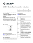
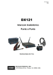
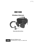
EN5040/EN5040-T/EN5040-20T High Power
Repeater with Transformer
1.4 High Power Repeater Internal Components
A
B
Installation and Operation Manual
C
1 Overview
The Inovonics high power repeater receives, decodes and retransmits
signals at enhanced power from Inovonics devices. It acts as a range
expander for any valid Inovonics transmission, including signals from other
high power repeaters. High power repeaters can be layered as necessary,
allowing Inovonics systems to scale from small commercial sites to
complete campuses consisting of several buildings. The high power
repeater features AC power loss and jam detection, as well as case tamper
and wall tamper detection. Input power is provided by listed class 2
transformer, Good Power Electronics, Ltd. T48141428V010G or
T48141428V020G, MPI-NEO Co., Ltd. W48A-K1429-2T.
J
1.1 Maximum Number of Repeaters for a UL 2560
Installation
To achieve the 99.99% alarm message reliability required for UL 2560
compliance, system installations must operate within the following limits for
end device and repeater counts.
End Devices
Maximum
Repeaters
150
397
250
386
350
375
500
360
1000
313
2000
238
3000
184
C
C Power
D Tamper input
G Battery
connector
H Tamper
mounting hole
J Messaging mode
selection pins
One 14VAC/120VAC-20VA power transformer
Three drywall anchors
Three mounting screws
One frequency band selection jumper
2 Installation and Startup
Figure 1 High power repeater front panel
B Transmit LED
A
A Housing release B Tamper button
tabs
spring
E Reset button
F Backup battery
•
•
•
•
1.3 High Power Repeater Front Panel
D
A
Figure 2 High power repeater internal components
1.5 What’s in the Carton
If you have any problems with this procedure, contact Inovonics technical
services:
• E-mail: [email protected]
• Phone: (800) 782-2709; (303) 939-9336
B
F
I
E
I Frequency
selection pins
1.2 Inovonics Contact Information
A
H
D
Note: For UL 2560 installations, refer to the EN6080 Area Control Gateway
User Manual; for other UL installations, refer to the EN4216MR Installation
and Operation Manual, the EN4232MR Installation and Operation Manual,
or the EN7285 Installation Instructions.
A Decode LED
D Power LED
G
C Low Battery Fault LED
Operation LEDs
Decode LED: Flashes when any recognizable RF transmission is received.
Transmit LED Lit when transmitting an RF transmission.
Low Battery Fault LED: Lit when the high power repeater has a low battery.
Power LED: Lit when receiving power. The LED lights green when the unit
is receiving line power; red when receiving battery power.
Note: If mapped to an output, the high power repeater will send the AC loss
message to the EN6080 area control gateway when receiving power from
the backup battery.
1.23.14 05066N © Inovonics, 2014 - www.inovonics.com
2.1 Installation Notes
• These products are designed to be maintained by professional
security technicians
• Products are tested for indoor use
• All products should be manually tested weekly
2.2 Select the Frequency Band
EchoStream devices are able to use a range of radio frequencies, and must
be configured for your geographic area. This device ships with a default
frequency range of 902-928 MHz for use in North America. If you are using
the device in North America, skip to 2.3, “Choose Messaging Mode”; if you
are using the device in Australia or New Zealand, you will need to configure
it.
1. Use a small screwdriver to press the top housing release tab and
separate the housing (Figure 2).
2. Place a selection jumper on the frequency band selection pins
appropriate to your geographic area (Figure 2).
• Place the jumper on the left two pins, marked AU, to set the frequency
range to 915-928 MHz for Australia.
• Place the jumper on the right two pins, marked NZ, to set the
frequency range to 921-928 MHz for New Zealand.
Note: Only devices set for use in North America are configured for UL
installations.
2.3 Choose Messaging Mode
The EchoStream commercial mesh network includes two kind of
messaging: broadcast messaging and directed messaging. The high power
repeater includes a messaging selection option to protect the integrity of
your system. The high power repeater ships with a default setting of
broadcast messaging. If you are installing the device in a broadcast
messaging network, skip to section 2.6, “Register the High Power
Repeater”; if you are installing the high power repeater in a directed
messaging network, you will need to configure it.
3. To set the high power repeater to directed messaging, remove the
selection jumper installed on the messaging mode selection pins.
Caution: Mount the high power repeater in a location removed from metal.
Metal objects (duct work, wire mesh screens, boxes) will reduce RF range.
2.4 Connect Power Cabling
Power must be connected to the high power repeater. To connect power to
the high power repeater:
4. Use a small screwdriver to press the housing release tab on the top or
bottom of the high power repeater (Figure 2); separate the housing.
5. Connect power cabling (Figure 2).
• Wire should be two-conductor 20AWG (or larger) stranded-tinned
copper with PVC insulation rated to 300 volts at 26°C (80°F). Wire
length should not exceed 100 meters (328 feet).
Note: For all UL installations, cabling must be UL Listed or Recognized,
Class 2 wire suitable for the application. Use two-conductor 20 AWG (or
larger) stranded-tinned copper, rated 300 volts, 60°C minimum. Wire length
should not exceed 100 meters.
• See section 1, “Overview” on page 1 for approved Class 2
transformers.
• Route the cable from the transformer to the unit through the left side of
the repeater, or through the oval knock-out section in the rear.
• Torque screw terminal to 0.25 N-m (2.18 lb-in).
Note: Do not secure transformer for Canadian installations.
2.5 Connect Battery Power
The high power repeater is shipped with a fully-charged backup battery.
You will need to connect the battery:
6. Plug the connector cable from the backup battery into the battery
connector (Figure 2).
2.6 Register the High Power Repeater
Although the high power repeater is functional upon startup, Inovonics
strongly recommends you register it using the EN6080 area control
gateway. Inovonics recommends all high power repeaters be supervised.
When supervised, the EN5040 and EN5040-T will send a check-in
message to the receiver every three minutes; the EN5040-20T will send a
check-in message every 20 minutes.
Note: In UL 2560 installations, the repeater sends a check-in message
every 20 minutes.
Note: Registration and supervision is required for UL installations.
Note: In UL 2560 installations, refer to the EN6080 Area Control Gateway
User Manual for registration information; in other UL installations, refer to
the EN4216MR Installation and Operation Manual, the EN4232MR
Installation and Operation Manual, or the EN7285 Installation Instructions.
Caution: The reset bit will not be sent when the high power repeater has a
low battery. Before registering the high power repeater, ensure the battery
is fully charged.
2.7 Mount the High Power Repeater
For best results, you will want to mount the high power repeater vertically,
so that the antennae are oriented as shown in Figure 3.
Antenna
Antenna
Caution: In UL 2560 installations, the unit must be mounted with the cable
opening facing downward as shown in Figure 3.
7. Use the provided anchors and screws to mount the high power repeater
in a location accessible for future maintenance.
• In large installations, high power repeaters should be mounted so that
every transmitter has multiple transmission paths to the EN6080 area
control gateway. This kind of redundancy preserves system integrity in
the event of temporary interruptions of any transmission path in the
system.
• For maximum efficiency, high power repeaters should be mounted
with as few obstacles as possible between them and the EN6080 area
control gateway.
• Always perform a walk test after mounting, activating each transmitter
assigned to the high power repeater and ensuring an appropriate
response.
2.8 Enable the Wall Tamper
The wall tamper must be enabled. If the high power repeater is removed
from the wall, the cutout on the back of the housing will detach, activating a
tamper alarm. To enable the wall tamper.
8. Attach one of the mounting screws to the wall through the tamper
mounting hole (Figure 2).
2.9 Close the Housing
The housing must be closed and the tamper spring in place to ensure the
security of your system.
9. Check that the tamper spring is in place and makes contact with the
high power repeater housing.
10. Close the housing.
3 US Patent Numbers
•
•
•
•
7,154,866
7,554,932
7,746,804
Other patents pending
4 Specifications
Housing: 6.5" x 3.5" x 1" (165 mm x 89 mm x 25 mm)
Weight: 7.14 oz (204 g)
Operating environment: All UL installations: 32 to 140°F (0 to 60°C), 90%
relative humidity, non-condensing; all other installations: -4 to 140°F (-20 to
60°C), 90% relative humidity, non-condensing
Power requirement: 14 VAC, 60 Hz, 250 mA
Battery capacity: 3.6 VDC nominal, 2900 mAh
Typical back-up battery life: 24 hours
Operating frequency: 915-928 MHz (Australia), 921-928 MHz (New
Zealand), 902-928 MHz (USA)
Battery charger operating environment: 32 to 140°F (0 to 60°C), 90%
relative humidity, noncondensing
Accessories: ACC650: weatherproof plastic enclosure for outdoor
installations; BAT850: replacement lithium-ion battery assembly
UL certifications for EN5040-T: UL 365, UL 636, UL 1023, ULC/ORDC1023-74, UL 1076, UL 1610
UL certifications for EN5040-20T: UL 2560 (see conditions below)
Note: For UL 2560 installations, Inovonics repeaters must have 20 minute
check-in times. Inovonics transmitters must have a minimum of 60 minute
check-in times.
Note: For UL 2560 installations, the EN5040-20T high power repeater may
be used with completed emergency call systems for assisted living and
independent living facilities
For UL 2560 certified system installations, the following Inovonics
EchoStream devices are approved for installation within maximum system
configuration limits defined in section 1.1 of this document:
• EN6080 area control gateway
• EN5040-20T high power repeater
• End devices (transmitters) with a minimum 60-minute check-in
interval, as follows:
Figure 3 High power repeater antenna orientation
1.23.14 05066N © Inovonics, 2014 - www.inovonics.com
2
- Fundamental devices which are subject to UL2560 certification
(pendant transmitters and OEM products using the Inovonics RF
module)
- Supplemental devices which are not subject to UL2560 system
certification but which may be used within a UL2560 certified system
(e.g. universal transmitters and activity sensors)
This warranty will apply only to Inovonics Products. Inovonics will not be
liable for any direct, incidental, or consequential damage or loss
whatsoever, caused by the malfunction of Product due to products,
accessories, or attachments of other manufacturers, including batteries,
used in conjunction with Inovonics Products.
Note: E-mail [email protected] for a copy of the CE Declaration of
Conformity.
Note: Users that have achieved certification and will install UL 2560
certified systems are responsible for labeling all fundamental devices with
the UL 2560 system certification mark.
Compatible receiver for UL 2560 installations: EN6080 area control
gateway
Compatible receiver for all other UL installations: EN4216MR, EN4232MR,
EN7285
US patent number 7,746,804
5 Television and Radio Interference
This equipment has been tested and found to comply with the limits for a
Class B digital device, pursuant to Part 15 of the FCC Rules. These limits
are designed to provide reasonable protection against harmful interference
in a residential installation. This equipment generates, uses and can
radiate radio frequency energy and, if not installed and used in accordance
with the instructions, may cause harmful interference to radio
communications. However, there is no guarantee that interference will not
occur in a particular installation. If this equipment does cause harmful
interference to radio or television reception, which can be determined by
turning the equipment off and on, the user is encouraged to try to correct
the interference by one or more of the following measures:
• Reorient or relocate the receiving antenna.
• Increase the separation between the equipment and receiver.
• Connect the equipment into an outlet on a circuit different from that to
which the receiver is connected.
• Consult the dealer or an experienced radio/TV technician for help.
6 FCC Part 15 and Industry Canada Compliance
This device complies with part 15 of the FCC Rules and Industry Canada
license-exempt RSS standard(s). Operation is subject to the following two
conditions: (1) this device may not cause interference, and (2) this device
must accept any interference, including interference that may cause
undesired operation of the device.
Le présent appareil est conforme aux CNR d'Industrie Canada applicables
aux appareils radio exempts de licence. L'exploitation est autorisée aux
deux conditions suivantes : (1) l'appareil ne doit pas produire de brouillage,
et (2) l'utilisateur de l'appareil doit accepter tout brouillage radioélectrique
subi, même si le brouillage est susceptible d'en compromettre le
fonctionnement.
7 Warranty/Disclaimer
Caution: Changes or modifications not expressly approved by the party
responsible for compliance could void the user's authority to operate the
equipment.
Inovonics Wireless Corporation ("Inovonics") warrants its products
("Product" or "Products") to conform to its own specifications and to be free
of defects in materials and workmanship under normal use for a period of
thirty-six (36) months from the date of manufacture. Within the warranty
period, Inovonics will repair or replace, at its option, all or any part of the
warranted Product. Inovonics will not be responsible for dismantling and/or
reinstallation charges. To exercise the warranty, the User ("User", "Installer"
or "Consumer") must work directly through their authorized distributor who
will be given a Return Material Authorization ("RMA") number by Inovonics.
Details of shipment will be arranged directly through the authorized
distributor.
This warranty is void in cases of improper installation, misuse, failure to
follow installation and operating instructions, alteration, accident or
tampering, and repair by anyone other than Inovonics.
This warranty is exclusive and expressly in lieu of all other warranties,
obligations or liabilities, whether written, oral, express, or implied. There is
no warranty by Inovonics that Inovonics product will be merchantable or fit
for any particular purpose, nor is there any other warranty, expressed or
implied, except as such is expressly set forth herein. In no event shall
Inovonics be liable for an incidental, consequential, indirect, special, or
exemplary damages, including but not limited to loss of profit, revenue, or
contract, loss of use, cost of down time, or interruption of business, nor any
claim made by distributor's customers or any other person or entity.
This warranty will not be modified or extended. Inovonics does not
authorize any person to act on its behalf to modify or extend this warranty.
1.23.14 05066N © Inovonics, 2014 - www.inovonics.com
3