1
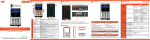
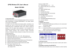
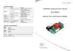
TABLE OF CONTENTS
__________________________________________________
3. PANELS
___________________________________________________
1.
2.
3.
4.
5.
6.
SPECIFICATIONS
FEATURES
PANELS
OPERATION
FUNCTIONS
RS232C INTERFACE
3.1 Front Panel
Black Panel:
To Indicator
RS232
1. SPECIFICATIONS
__________________________________________________
1.1.
1.2.
1.3.
1.4.
Output signal range:
-3.1000~+3.1000mV/V
Minimum step length:
0.0001mV/V
Linearity:
0.01%FS
Display:
LCD (122x32 dot-matrix, with back
light, Black characters on green light background)
1.5. Current Consumption:
80mA DC (with back light)
40mA DC (with back light).
2. FEATURES
__________________________________________________
2.1 Menu Mode
2.2 RS232C Interface
2.3 Display Back-light
2.4 Auto Power Off
2.5 Beeper
2.6 Baud Rate
2.7 Load Cell Bridge Resistance Selection
2.8 Excitation voltage: 5~12VDC
FIGURE 1
LOADCELL
3.2 Dimension:
170x75x300 (mm):
then shows in the following automatically alert seconds:
3.3 Signal Output Cable Wiring:
Pin1: +Excitation (+E)
Pin4: -Excitation (-E)
Pin2: +Signal (+S)
Pin3: -Signal (-S)
4.2
3.4 RS232 serial output (9 pin) wiring:
2
→
RXD
3
→
TXD
4
→
DTR
5
→
GND
Normal operation mode:
4.2.1 The display in normal operation mode is as Fig.5:
Signal area (Top left corner):
Display strength of output signal.
For example: If display is 1.000mV/V and excitation voltage is
10V, then the output voltage is 10mV.
3.5 Back panel DIP switch for input resistor setting:
Timer for auto power off (Top right corner):
Upper is ON Lower is OFF:
Input resistance (Ohm) Switch1
Simulator will power off automatically, when timer counts
Switch2
Switch3
Switch4
350
none
ON
ON
ON
700
none
ON
ON
OFF
1000
none
OFF
ON
ON
2000
none
OFF
OFF
OFF
3.6 Recharge time for battery:
10hours.
down to zero and sounds alarm for a period of no-key press.
Step length area (Bottom left corner):
Adjust a different output signal when press ↑ key
(increase) ↓ 0 key (decrease).
Bar-graph area will increase a step when the output signal increases
0.1000mV/V.
4.2.2
Function keys:
4. OPERATION
↑ Press this key once to increase signal one step:
_____________________________________________________
↓ Press this key once to decrease output signal one step:
4.1 Power on and initial display:
U = 8.5V
PA8201
[V1.0]
Yuyao Pacific Auto-control
Put power supply switch to 1(ON) (see Fig.3) and press
Press this once to increase output by 10 steps:
Press this key once to decrease output by 10 steps:
Press this key and hold, the output signal will zero after beeping
3 times;
+ Press these two keys simultaneously to enter menu setting mode.
5.3.2
5. FUNCTION MENU MODE
F2 (for power):
(2)Power
% Auto –down:
5.1 Selection of function menu:
F1 Display
Setting
!
LCD
Contrast
Fig.8
!
Back-light
Selector
!
Press # key to enter F3.
Back-light
Timer
5.3.3
"
F2 Power
Setting
F3 Beep
Serial
timer (Yes/No)
! Beep select !
"
(Yes/No)
F3 (for keyboard):
(3) keyboard
-> Beep on touch:
Auto-back:
! Auto power off
"
3:00
3 min
Serial Comm.
(Yes/No)
3:00
Yes
Yes
RS232 selectable
Fig. 9
Press #key to enter F4.
F4 Baud rate select 2400,
2800, 9600
5.3.4
F4
RS232
% Baud rate
5.2 Function key in mean mode
# !Press these two keys simultaneously in normal operation
Mode to enter menu mode.
3:00
9600
Fig. 10
6. RS-232C COMMUNICATION
# Press this key to select sub-menu (F1~F2):
! Press this key to select a function in a sub-menu:
$ or "Press this key to change the selection of functions.
5.3 Display in function menu mode:
5.3.1
F1 (for display):
Note: Cursor “→” in figures as follows is indicating the
selection.
(1)Indicator
Contrast:
Back Light:
%B.Light off:
3:00
1
Yes
3 sec
Fig. 7
Press #key to enter F2.
6.1 RS232C wiring:
Signal
Generator
Serial
X2
Line
25pms
9 pins
Line
3
TXD
3
2
RXD
2
RXD
2
3
TXD
4
DTR
20
4
DTR
5
GND
7
5
GND
6.2 RS-232C parameter settings:
Baud rate:
2400/4800/9600:
Check bit:
None
Stop bit:
1:
Data bit:
8.
6.3 Communication Protocol:
Sign
ESC
27 (decimal):
CR
13 (decimal):
LF
10 (decimal)
XXXX-----------signal, in hexadecimal:
xxxx-------------step length, in hexadecimal.
6.4 Communication Rules:
Signal transmit range:
-3.1000~+3.1000mV/V
Step length transmit range : 0.0001~1.0000mV/V
Decimal point is fixed, none transmit.
Characters transmitted are “0, 1, 2, 3, 4, 5, 6, 7, 8, 9, S, s, :”
Transmit from higher byte to low, the front is for signal; the
following 5 bytes are for step length.
For example:
Signal is +2.1234 and step length is 0.1000, then transmit
as below ESC
S:+21234
s: 01000
CR
LF