1
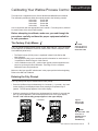
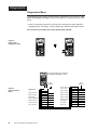
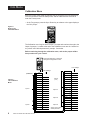
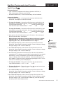
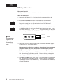
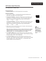
Calibrating Watlow Process Controls (Applies to Series 981, 982, 983, 984, 986, 987, 988, 989) Calibration Manual Watlow Controls, 1241 Bundy Blvd., P.O. Box 5580, Winona, MN 55987-5580, Phone: 507/454-5300, Fax: 507/452-4507 W988-CM10-9345 November, 1993 $5.00 Made in the U.S.A. Printed on Recycled Paper Contents Page Description Calibrating Your Watlow Process Control 3 3 4 6 7 7 7 7 The Factory (Fcty) Menus Entering the Fcty Prompt Diagnostics Menu Calibration Menu Calibration Restore Prompt The dFL Prompt Input Calibration Output Calibration Calibration Procedures 8 9 10 11 12 13 14 14 15 16 17 17 2 Low Gain Thermocouple Input High Gain Thermocouple Input RTD Input mA Process Input VDC Process Input mVDC Process Input Slidewire Feedback Input Current Transformer Input mA Process Output 1 and 2 VDC Process Output 1 and 2 mA Retransmit Output 3 VDC Retransmit Output 3 WATLOW Series 988 Calibration Manual Calibrating Your Watlow Process Control Menus/Prompts This manual is a supplement to the Series 981/982 and 988/989 User’s Manual. The calibration procedures within this manual pertain to the following controls: Series 981 Series 986 Series 982 Series 987 Series 983 Series 988 Series 984 Series 989 Use in conjunction with the appropriate user’s manual. From this point on, 988 will be used in place of the above listed models. Before attempting to calibrate, make sure you read through the procedures carefully and have the proper equipment called for in each procedure. The Factory (Fcty) Menus NOTE: The Fcty prompt consists of three menus: PLOC, diAg, and CAL. The Fcty prompt will not appear if the hardware lockout DIP switch is ON. Refer to Chapter 1 of the User’s Manual (white book). The Fcty menu is not available on a Series 981 - 984. • The Panel Lockout (PLOC) menu is explained in detail in the Series 988 User’s Manual. • The Diagnostics (diAg) menu contains specific information for each control. It is explained in detail on Page 4 of this manual. • In the Calibration menu (CAL), various input signals must be supplied for the control to go through its auto calibration. See Page 5 for the complete Calibration menu and procedures. Make sure the input type DIP switches are in the proper position before beginning. Refer to the 988 User’s Manual. Entering the Fcty Prompt The Fcty prompt can only be entered from the SEt prompt. • Press the Up/Down keys simultaneously for 3 seconds ( ± 1 second). Any inadvertent change in the displayed data, when pressing the Up/Down keys is ignored. The SEt prompt appears in the lower display. • Continue pressing the Up/Down keys simultaneously for another 3 seconds and the Fcty prompt appears in the lower display with PLOC in the upper display. For 981 - 984 units the dIAg prompt appears in the upper display. WATL W 3 Seconds WATL W PROCESS L1 L2 DEV % OUT L3 PROCESS L4 DISPLAY L1 L2 DEV % OUT AUTO MAN L3 L4 DISPLAY AUTO MAN MODE SERIES 988 Figure 1 Entering the Fcty Prompt MODE NOTE: The Series 981 - 984 units have a Hold/Run key in place of the Auto/Man key. SERIES 988 WATLOW Series 988 Calibration Manual 3 Diagnostics Diagnostics Menu The Diagnostics menu (diAg) contains specific information for each control. This menu is for factory use only, but can be accessed for viewing or technical assistance. • At the Fcty prompt, press the Up or Down key to advance the upper display to the diAg prompt. See below. Use the Mode key to advance through this menu. Do not enter any readings here; make photocopies instead. WATL W Figure 2 Entering the Diagnostics Menu WATL W PROCESS L1 L2 DEV % OUT PROCESS L3 L4 L1 L2 DEV DISPLAY % OUT AUTO MAN L3 L4 DISPLAY AUTO MAN MODE MODE SERIES 988 SERIES 988 WATL W PROCESS L1 L2 L3 DEV % OUT Press the Mode key to advance through the Diagnostics menu. L4 DISPLAY AUTO MAN MODE SERIES 988 Figure 3 The Diagnostics Menu 4 (Diagnostics) (diAg) Factory ship date DAtE ( ) Software revision SOFt ( ) Serial number Sn _ _ ( ) Ambient temperature AMb ( ) Ambient A/D count Acnt ( ) Ground A/D count gnd ( ) Input 1 A/D count cnt1 ( ) WATLOW Series 988 Calibration Manual Your Readings Your Readings ( ) Input 2 A/D count cnt2 Input 1 module itY1 ( ) Input 2 module itY2 ( ) Output 1 module OtY1 ( ) Output 2 module OtY2 ( ) Output 3 module OtY3 ( ) Output 4 module OtY4 ( ) Test displays dISP ( ) Test outputs tout ( ) Open Loop OPLP ( ) When contacting the factory for technical assistance, make sure you have the information documented from the following prompts. All prompts in this menu are read only. Diagnostics Date: This prompt represents the date the final control test was performed. The first two numbers are the week (01 through 52), and the last two numbers are the year. DAtE Software Revision: Signifies the control software revision. SOFt Serial Number: Represents the control serial number. The first two LED’s in the upper display are Sn followed by the serial number. The number is six digits in length beginning with the last two digits in the upper display, and wrapping around to the lower display where the remaining four digits are shown. Ambient Temperature: The ambient temperature at the Input 1 terminals, in °F. Sn AMb Acnt, gnd, cnt1 and cnt2 are for factory use only. itY1, itY2, OtY1, OtY2, OtY3, and OtY4 are input and output module types respectively. Below is a listing of the displays, and what they represent. Please document the displays before contacting the factory for technical assistance. Input Types nonE No module tc Thermocouple only Curr Current detect SLid Slidewire UOFF Universal OFF Urtd Universal RTD Output Types nonE No module SSR1 0.5A SSR SS1S 0.5A SSR with suppression SSr2 2.0A SSR SS2S 2.0A SSR with suppression 2SSr Two 0.5A SSR dc Switched DC 2dc Two switched DC rLYc Form C relay rLcS Form C relay with suppression Utch UtcL UMu UPrc Ei2 Curr Universal thermocouple high gain Universal thermocouple low gain Universal millivolts Universal process Event input 2 Heater current rLAB rABS 2rLY Proc Uret Iret SPLY 232 485 Relay A/B Relay A/B with suppression Two relays Process Voltage/retransmit Current/retransmit Power supply RS-232 communications EIA-485/422 communications Display: Press the Up or Down key to change the upper display from no to YES. Each display and LED is tested. If any display or LED is absent contact the factory. Test Output: This prompt tests each output. As the Up or Down key is pressed, it cycles through the available outputs. Once the corresponding LED is lit the respective output is energized. Press the Up or Down key again to advance to the next output. If any LED’s are non-functional, or if the outputs fail to energize, contact the factory. Open Loop: This prompt enables open heater or shorted sensor detect, and enables the error code function. This prompt only functions in the proportional control mode. The error message OPLP flashes in the lower display when on is selected and heat or cool is full ON and no temperature change has occurred over a period of time. The time period is based on the system characteristics. Range: on or OFF Default: OFF itY1 itY2 OtY1 OtY2 OtY3 OtY4 dISP tout OPLP This menu will continue looping through the parameters until you press the Display key to return to the Display loop. WATLOW Series 988 Calibration Manual 5 CAL Menu Calibration Menu Enter the Factory menu again by pressing the Up and Down keys simultaneously for three seconds to enter the Setup menu, and an additional three seconds to enter the Factory menu. • At the Fcty prompt, press the Up or Down key to advance to the upper display to the CAL prompt. Figure 4 Entering the Calibration Menu WATL W PROCESS L1 L2 DEV % OUT L3 L4 DISPLAY AUTO MAN MODE SERIES 988 The Calibration menu begins with the Input 1 prompts and continues through to the Output 3 prompts. Located at the end of the Calibration menu are the “restore factory values” and “default parameters” prompts. See below. Before continuing through the calibration menu, refer to the proper calibration procedure for your control. WATL W PROCESS L1 L2 DEV % OUT L3 Press the Mode key to advance through the Diagnostics menu. L4 DISPLAY AUTO MAN Your Settings MODE SERIES 988 Your Settings (CAL) (Calibration) Figure 5 The Calibration Menu Input #1 A 50 ( ) A 00 ( ) tc ( ) b10U ( ) b 0U ( ) b20A ( ) ( ) ( ) A 20 ( ) b 0u ( ) A 15 ( ) b100 ( ) A380 ( ) 14 ( ) 1 20 ( ) 10 ( ) A20A ( ) 1 10 ( ) A 4A ( ) 24 ( ) ( ) 2 20 ( ) ( ) A 0u Output #1 ( ) Output #2 A100 ( ) 20 b 50 ( ) 2 10 ( ) b 00 ( ) 3 LO ( ) ( ) 3 HI ( ) ( ) Restore factory values rSt ( ) Default parameters dFL ( ) b 0H b 20 WATLOW Series 988 Calibration Manual ( ) A 0H A 0U 6 ( ) b380 b 4A A10U ( ) Input #2 Input #2 (cont.) b 15 Output #3 rSt/dFL Prompts Calibration Restore Prompt If you make a mistake while calibrating your control, the rSt prompt near the end of the calibration menu restores the original factory calibration settings. At the rSt prompt, simply press the Up or Down key to change the upper display to read YES; press the Mode key. The original factory calibration values are restored. The dFL Prompt To set the operating parameter defaults for either domestic or international, use the dFL (default) prompt at the end of the Calibration menu. Once you have entered the Calibration menu, use the Mode key to advance to the dFL prompt. Press the Up or Down key to change the upper display to US or SI. For domestic prompts, select US and receive: • °F • Rate in minutes • Proportional band in degrees or units • Reset in repeats per minute For international prompts, select SI and receive: • °C • Derivative in minutes • Proportional band in % of span • Integral in minutes per repeat Input Calibration Once you enter the Factory menu, press the Up or Down key until the CAL prompt appears in the upper display with Fcty in the lower display. Press the Mode key to advance to the first calibration prompt. See Figure 2 on the previous page. The upper display shows the prompt default no, while the lower display indicates the input signal prompt. Each input calibration prompt is preceded by an A or B, signifying Input 1 or 2 respectively. Refer to the Calibration menu on the previous page again. Before advancing to the next prompt when calibrating, always apply the correct input signal and allow to stabilize for 10 seconds before changing the upper display to YES. If the parameter is left at no, the calibration information will not be entered. Once the appropriate parameters are calibrated, press the Display key to exit the CAL menu. Output Calibration After calibrating the Input 1 and 2 prompts, the next prompts apply to Output 1 through 3 which are for process outputs only. Model numbers affected are Output 1 98_ _ - _ _ F _ - _ _ _ _ Output 2 98_ _ - _ _ _ F - _ _ _ _ Output 3 98_ _ - _ _ _ _ - M_ _ _ 98_ _ - _ _ _ _ - N_ _ _ The prompt in the lower display indicates the output signal while the upper display reads a hexidecimal value which matches the output value. The upper display value is for internal use only and should be ignored. Each output calibration prompt is preceded by a 1, 2, or 3, signifying Output 1, 2, or 3 respectively. If your unit does not have Output 2 or 3, these prompts will not appear. Once the appropriate parameters are calibrated, press the Display key to exit the CAL menu. WATLOW Series 988 Calibration Manual 7 Low Gain T/C Low Gain Thermocouple Input Procedure For all thermocouple inputs excluding Type R, S and B Equipment Required • Type J reference compensator with reference junction at 32°F/0°C, or Type J thermocouple calibrator set at 32°F/0°C • Precision millivolt source, 0 - 50mV minimum range, 0.01mV resolution Setup and Calibration 1. Connect the AC voltage L1, L2 and ground to the proper terminals on the Series 988. See Chapter 2 in the user's manual. 2. For Input #1 calibration: Connect the millivolt source to terminal #9 (+) and terminal #10 (-) on the 988 terminal strip. Use 20 to 24 gauge copper wire. If you have model number 98_ _ - 2 _ _ _ - _ _ _ _, remove the control from the case and set the Input 1 DIP switches to: 1 OFF 2 ON 3 ON For Input #2 calibration: Connect the millivolt source to terminal #19 (+) and terminal #20 (-) on the 988 terminal strip. Use 20 to 24 gauge copper wire. If you have model number 98_ _ - _2 _ _ - _ _ _ _, remove the control from the case and set the Input 2 DIP switches to: 1 OFF 2 ON 3 ON 3. Apply power to the unit and let it warm up for 15 minutes. After warm-up, put the unit in the CAL menu. See Page 6. NOTE: Any prompt beginning with an “A” applies to Input 1. Those beginning with a “B” apply to Input 2. When performing calibration procedures, always do the Input 1 prompts (beginning with an “A”) first, then continue on to the Input 2 prompts (beginning with a “B”). See the Calibration menu on Page 6. 4. At the A 50 prompt, or the B 50 prompt, enter 50.00mV from the millivolt source to the Series 988. Allow at least 10 seconds to stabilize. Press the Up key to change the upper display to YES. Press the Mode key. 5. At the A 00 prompt, or the B 00 prompt, enter 0.00mV from the millivolt source to the Series 988. Allow at least 10 seconds to stabilize. Press the Up key to change the upper display to YES. Press the Mode key. 6. At the tc prompt, disconnect the millivolt source, and connect the reference compensator or T/C calibrator to terminal #9 (+) and terminal #10 (-) on the 988 terminal strip. If using a compensator, turn it on and short the input wires. When using a Type J calibrator, set it to simulate 32°F/0°C. Allow 10 seconds for the control to stabilize. Press the Up key to change the upper display to YES. To conclude the T/C calibration, press the Display key. 8 WATLOW Series 988 Calibration Manual High Gain T/C High Gain Thermocouple Input Procedure Type R, S and B only Equipment Required • Type J reference compensator with reference junction at 32°F/0°C, or Type J thermocouple calibrator set at 32°F/0°C • Precision millivolt source, 0 - 50mV minimum range, 0.01mV resolution Setup and Calibration 1. Connect the AC voltage L1, L2 and ground to the proper terminals on the Series 988. See Chapter 2 in the user's manual. 2. For Input #1 calibration: Connect the millivolt source to terminal #9 (+) and terminal #10 (-) on the 988 terminal strip. Use 20 to 24 gauge copper wire. If you have model number 98_ _ - 2 _ _ _ - _ _ _ _, remove the control from the case and set the Input 1 DIP switches to: 1 OFF 2 ON 3 ON For Input #2 calibration: Connect the millivolt source to terminal #19 (+) and terminal #20 (-) on the 988 terminal strip. Use 20 to 24 gauge copper wire. If you have model number 98_ _ - _2 _ _ - _ _ _ _, remove the control from the case and set the Input 2 DIP switches to: 1 OFF 2 ON 3 ON 3. Apply power to the unit and let it warm up for 15 minutes. After warm up put the unit in the CAL menu. See Page 6. When performing calibration procedures, always do the Input 1 prompts (beginning with an “A”) first, then continue on to the Input 2 prompts (beginning with a “B”). See the Calibration menu on Page 6. 4. At the A 50 or B 50 prompt, enter 50.00mV from the millivolt source to the Series 988. Allow at least 10 seconds to stabilize. Press the Up key to change the upper display to YES. Press the Mode key. 5. At the A 00 or B 00 prompt, enter 0.00mV from the millivolt source to the Series 988. Allow at least 10 seconds to stabilize. Press the Up key to change the upper display to YES. Press the Mode key. NOTE: Any prompt beginning with an “A” applies to Input 1. Those beginning with a “B” apply to Input 2. 6. At the tc prompt, disconnect the millivolt source, and connect the reference compensator or T/C calibrator to terminal #9 (+) and terminal #10 (-) on the 988 terminal strip. If using a compensator, turn on and short the input wires. If using a J calibrator, set it to simulate 32°F/0°C. Allow 10 seconds for the control to stabilize. Press the Up key to change the upper display to YES. To conclude the T/C calibration, press the Display key. 7. For Input #1 calibration: Remove the control from the case and set the Input #1 DIP switches to: 1 OFF 2 ON 3 OFF 8. For Input #2 calibration: Remove the control from the case and set the Input #2 DIP switches to: 1 OFF 2 ON 3 OFF 9. At the A 0H or B 0H prompt, enter 0.00 mV from the millivolt source to the Series 988. Allow at least 10 seconds to stabilize. Press the Up key to change the upper display to YES. Press the Mode key. 10.At the A 20 or B 20 prompt, enter 20.00 mV from the millivolt source to the Series 988. Allow at least 10 seconds to stabilize. Press the Up key to change the upper display to YES. Press and hold the Mode key, while also pressing the Up key until the lower display reads tc. WATLOW Series 988 Calibration Manual 9 RTD RTD Input Procedure Equipment Required • 1K precision decade box with 0.01 resolution Setup and Calibration 1. Connect the AC voltage L1, L2 and ground to the proper terminals on the Series 988. See Chapter 2 in the user's manual. 2. For Input #1 calibration: Connect the decade box to terminals #8, 9 and 10 on the 988 terminal strip, see below. Use 20 to 24 gauge copper wire. Remove the control from the case and set the Input 1 DIP switches to: 1 OFF 2 OFF 3 ON For Input #2 calibration: Connect the decade box to terminal #18, 19 and 20 on the 988 terminal strip, see below. Use 20 to 24 gauge copper wire. If you have model number 98_ _ - _2 _ _ - _ _ _ _, remove the control from the case and set the Input 2 DIP switches to: 1 OFF 2 OFF 3 ON NOTE: Any prompt beginning with an “A” applies to Input 1. Those beginning with a “B” apply to Input 2. H To 8 or 18 L To 9 or 19 G To 10 or 20 Ω Series 98X Terminals General Radio Model #1433-T 3. Apply power to the unit and let it warm up for 15 minutes. After warm up put the unit in the CAL menu. See Page 6. When performing calibration procedures, always do the Input 1 prompts (beginning with an “A”) first, then continue on to the Input 2 prompts (beginning with a “B”). See the Calibration menu on Page 6. 4. At the A 15 or B 15 prompt, enter 15.00 from the decade box to the Series 988. Allow at least 10 seconds to stabilize. Press the Up key to change the upper display to YES. Press the Mode key. 5. At the A380 or B380 prompt, enter 380.00 from the decade box to the Series 988. Allow at least 10 seconds to stabilize. Press the Up key to change the upper display to YES. Press the Mode key. To conclude the RTD calibration, press the Display key. 10 WATLOW Series 988 Calibration Manual mA Process Input mA Process Input Procedure 0 to 20mA and 4 to 20mA units Equipment Required • Precision current source, 0-20mA range with 0.01mA resolution Setup and Calibration 1. Connect the AC voltage L1, L2 and ground to the proper terminals on the Series 988. See Chapter 2 in the user's manual. 2. For Input #1 calibration: Connect the voltage source to terminal #8 (-) and terminal #10 (+) on the 988 terminal strip. Use 20 to 24 gauge copper wire. Remove the control from the case and set the Input 1 DIP switches to: 1 ON 2 ON 3 ON For Input #2 calibration: Connect the voltage source to terminal #18 (-) and terminal #20 (+) on the 988 terminal strip. Use 20 to 24 gauge copper wire. Remove the control from the case and set the Input 2 DIP switches to: 1 ON 2 ON 3 ON 3. Apply power to the unit and let it warm up for 15 minutes. After warm up put the unit in the CAL menu. See Page 6. When performing calibration procedures, always do the Input 1 prompts (beginning with an “A”) first, then continue on to the Input 2 prompts (beginning with a “B”). See the Calibration menu on Page 6. 4. At the A20A or B20A prompt, enter 20.00mA from the current source to the Series 988. Allow at least 10 seconds to stabilize. Press the Up key to change the upper display to YES. Press the Mode key. NOTE: Any prompt beginning with an “A” applies to Input 1. Those beginning with a “B” apply to Input 2. 5. At the A 4A or B 4A prompt, enter 4.00mA from the current source to the Series 988. Allow at least 10 seconds to stabilize. Press the Up key to change the upper display to YES. Press the Mode key. To conclude the current process calibration, press the Display key. WATLOW Series 988 Calibration Manual 11 VDC Process Input VDC Process Input Procedure 0 to 5VDC and 0 to 10VDC units Equipment Required • Precision Voltage source 0-10 volt minimum range with .001 volt resolution. Setup and Calibration 1. Connect the AC voltage L1, L2 and ground to the proper terminals on the Series 988. See chapter 2 in the user’s manual. 2. For Input #1 calibration: Connect the voltage source to terminal #9 (+) terminal #10 (-) on the 988 terminal strip. Use 20 to 24 gauge copper wire. Remove the control from the case and set the Input 1 DIP switches to: 1 ON 2 ON 3 ON For Input #2 calibration: Connect the voltage source to terminal #19 (+) and #20 (-) on the 988 terminal strip. Use 20 to 24 gauge copper wire. Remove the control from the case and set the Input 2 DIP switches to: 1 ON 2 ON 3 ON 3. Apply power to the unit and let it warm up for 15 minutes. After warm up put the unit in the CAL menu. See Page 6. NOTE: Any prompt beginning with an “A” applies to Input 1. Those beginning with a “B” apply to Input 2. When performing calibration procedures, always do the Input 1 prompts (beginning with an “A”) first, then continue on to the Input 2 prompts (beginning with a “B”). See the Calibration menu on Page 6. 4. At the A10U or B10U prompt, enter 10.000 volts from the voltage source to the Series 988. Allow at least 10 seconds to stabilize. Press the Up key to change the upper display to YES. Press the Mode key . 5. At the A 0U or B 0U prompt, enter 0.000 volts from the voltage source to the Series 988. Allow at least 10 seconds to stabilize. Press the Up key to change the upper display to YES. Press the Mode key . To conclude the voltage process calibration press the Display key. 12 WATLOW Series 988 Calibration Manual mVDC Process Input mVDC Process Input Procedure 0 to 50mVDC and 0 to 100mVDC units Equipment Required • Precision millivolt source, 0-100mV minimum range with 0.001mV resolution Setup and Calibration 1. Connect the AC voltage L1, L2 and ground to the proper terminals on the Series 988. See Chapter 2 in the user's manual. 2. For Input #1 calibration: Connect the millivolt source to terminal #8 (-) and terminal #10 (+) on the 988 terminal strip. Use 20 to 24 gauge copper wire. Remove the control from the case and set the Input 1 DIP switches to: 1 ON 2 OFF 3 ON For Input #2 calibration: Connect the millivolt source to terminal #18 (-) and terminal #20 (+) on the 988 terminal strip. Use 20 to 24 gauge copper wire. Remove the control from the case and set the Input 2 DIP switches to: 1 1 ON 2 OFF 3 ON 3. Apply power to the unit and let it warm up for 15 minutes. After warm up put the unit in the CAL menu. See Page 6. When performing calibration procedures, always do the Input 1 prompts (beginning with an “A”) first, then continue on to the Input 2 prompts (beginning with a “B”). See the Calibration menu on Page 6. 4. At the A 0U or B 0U prompt, enter 0.000mV from the millivolt source to the Series 988. Allow at least 10 seconds to stabilize. Press the Up key to change the upper display to YES. Press the Mode key. NOTE: Any prompt beginning with an “A” applies to Input 1. Those beginning with a “B” apply to Input 2. 5. At the A100 or B100 prompt, enter 100.00mV from the voltage source to the Series 988. Allow at least 10 seconds to stabilize. Press the Up key to change the upper display to YES. Press the Mode key. To conclude the millivolt process calibration, press the Display key. WATLOW Series 988 Calibration Manual 13 Slidewire/Current Slidewire Feedback Input Procedure Equipment Required • 1K precision decade box with 0.01 resolution Setup and Calibration 1. Connect the AC voltage L1, L2 and ground to the proper terminals on the Series 988. See Chapter 2 in the user's manual. 2. Connect the decade box to terminal #18 and #20 on the 988 terminal strip. Place a jumper wire between terminal #19 and #20. Use 20 to 24 gauge copper wire. 3. Apply power to the unit and let it warm up for 15 minutes. After warm up put the unit in the CAL menu. See Page 6. 4. At the B 15 prompt, enter 1000.00 from the decade box to the Series 988. Allow at least 10 seconds to stabilize. Press the Up key to change the upper display to YES. Press the Mode key. 5. At the B380 prompt, remove the jumper from terminals #19 and #20 and place it between terminals #18 and #19. Allow at least 10 seconds to stabilize. Press the Up key to change the upper display to YES. Press the Mode key. To conclude the slidewire feedback calibration, press the Display key. Current Transformer Input Procedure Equipment Required • DC source, 50mA minimum sourcing capacity, 0 - 5V minimum range Setup and Calibration 1. Connect the AC voltage L1, L2 and ground to the proper terminals on the Series 988. See Chapter 2 in the user's manual. 2. Connect the voltage source to terminal #18 and terminal #20 on the 988 terminal strip. Use 20 to 24 gauge copper wire. 3. Apply power to the unit and let it warm up for 15 minutes. After warm up put the unit in the CAL menu. See Page 6. 4. At the B 50 prompt, enter 4.72VDC from the voltage source to the Series 988. Allow at least 10 seconds to stabilize. Press the Up key to change the upper display to YES. Press the Mode key. 5. At the B 00 prompt, enter 0.00VDC from the voltage source to the Series 988. Allow at least 10 seconds to stabilize. Press the Up key to change the upper display to YES. Press the Mode key. To conclude the current transformer input calibration, press the Display key. 14 WATLOW Series 988 Calibration Manual mA Process Output mA Process Output 1 & 2 Procedure Equipment Required • 4 1/2 digit digital multimeter Setup and Calibration 1. Connect the AC voltage L1, L2 and ground to the proper terminals on the Series 988. See Chapter 2 in the user's manual. 2. For Output #1 calibration: Connect the digital multimeter to terminal #12 (+) and terminal #14 (-). Set the DMM to read a range of 0 to 20mA. Connect the leads of the DMM to measure current. For Output #2 calibration: Connect the digital multimeter to terminal #15 (+) and terminal #17 (-). Set the DMM to read a range of 0 to 20mA. Connect the leads of the DMM to measure current. 3. Apply power to the unit and let it warm up for 15 minutes. After warm up put the unit in the CAL menu. See Page 6. When performing calibration procedures, always do the Output 1 prompts (beginning with a “1”) first, then continue on to the Output 2 prompts (beginning with a “2”). See the Calibration menu on Page 6. 4. At the 1 4 or 2 4 prompt, the multimeter should read approximately 4 mA. Use the Up or Down keys to adjust the reading on the multimeter for 3.85mA ±.05mA. Allow the control to stabilize for 10 seconds. Press the Mode key to enter and advance to the next prompt. NOTE: Any prompt beginning with a “1” applies to Output 1. Those beginning with a “2” apply to Output 2. 5. At the 1 20 or 2 20 prompt, use the Up or Down keys to adjust the reading on the multimeter for 20.15mA ±.05mA. Allow the control to stabilize for 10 seconds. Press the Mode key to enter and advance to the next prompt. To conclude the process output calibration, press the Display key. WATLOW Series 988 Calibration Manual 15 VDC Process Output VDC Process Output 1 & 2 Calibration Equipment Required • 4 1/2 digit Digital Multimeter Setup and Calibration 1. Connect the AC voltage L1, L2 and ground to the proper terminals on the Series 988. See Chapter 2 in the user's manual. 2. For Output #1 calibration: Connect the digital voltmeter to terminal #13 (+) and terminal #14 (-). Set the DVM to read a range of 0 to 10VDC. Connect the leads of the DVM to measure volts DC. For Output #2 calibration: Connect the digital multimeter to terminal #16 (+) and terminal #17 (-). Set the DVM to read a range of 0 to 10VDC. Connect the leads of the DVM to measure volts DC. 3. Apply power to the unit and let it warm up for 15 minutes. After warm up put the unit in the CAL menu. See Page 6. NOTE: Any prompt beginning with a “1” applies to Output 1. Those beginning with a “2” apply to Output 2. When performing calibration procedures, always do the Output 1 prompts (beginning with a “1”) first, then continue on to the Output 2 prompts (beginning with a “2”). See the Calibration menu on Page 6. 4. At the 1 0 or 2 0 prompt, the multimeter should read approximately 0 Volts. Use the Up or Down keys to adjust the reading on the multimeter for 0.0VDC ± 0.1VDC. Allow the control to stabilize for 10 seconds. Press the Mode key to enter, and advance to the next prompt. 5. At the 1 10 or 2 10 prompt, use the Up or Down keys to adjust the reading on the multimeter for 10.0VDC ± 0.1VDC. Allow the control to stabilize for 10 seconds. Press the Mode key to enter, and advance to the next prompt. To conclude the process output calibration, press the Display key. 16 WATLOW Series 988 Calibration Manual Retransmit mA Retransmit Output 3 Procedure Equipment Required • 4 1/2 digit Digital Multimeter Setup and Calibration 1. Connect the AC voltage L1, L2 and ground to the proper terminals on the Series 988. See Chapter 2 in the user’s manual. 2. Connect the digital multimeter to terminal #1 (+) and terminal #2 (-). Set the DVM to read a range of 0 to 20mA. Connect the leads of the DVM to measure current. 3. Apply power to the unit and let it warm up for 15 minutes. After warm up put the unit in the CAL menu. See Page 6. 4. At the 3 LO prompt, the multimeter should read approximately 0.1mA. Use the Up or Down keys to adjust the reading on the multimeter for 0.00mA ± 0.05mA. Allow the control to stabilize for 10 seconds. Press the Mode key to enter and advance to the next prompt. 5. At the 3 HI prompt, use the Up or Down keys to adjust the reading on the multimeter for 20mA ±.05mA. Allow the control to stabilize for 10 seconds. Press the Mode key to enter and advance to the next prompt. To conclude the process retransmit output calibration, press the Display key. VDC Retransmit Output 3 Calibration Equipment Required • 4 1/2 digit Digital Multimeter Setup and Calibration 1. Connect the AC voltage L1, L2 and ground to the proper terminals on the Series 988. See Chapter 2 in the 988 User’s Manual. 2. For Output #1 calibration: Connect the digital multimeter to terminal #1 (+) and terminal #2 (-). Set the DVM to read a range of 0 to 10VDC. Connect the leads of the DVM to measure volts DC. 3. Apply power to the unit and let it warm up for 15 minutes. After warm up put the unit in the CAL menu. See Page 6. 4. At the 3 LO prompt, the multimeter should read approximately 0 volts. Use the Up or Down keys to adjust the reading on the multimeter for 0.0VDC ±0.1 volt. Allow the control to stabilize for 10 seconds. Press the Mode key to enter, and advance to the next prompt. 5. At the 3 HI prompt, use the Up or Down keys to adjust the reading on the multimeter for 10.0VDC ±0.1VDC. Allow the control to stabilize for 10 seconds. Press the Mode key to enter, and advance to the next prompt. To conclude the voltage process retransmit output calibration, press the Display key. WATLOW Series 988 Calibration Manual 17 18 WATLOW Series 988 Calibration Manual Watlow Process Controls Calibration Manual Watlow Controls, 1241 Bundy Blvd., P.O. Box 5580, Winona, MN 55987-5580, Phone: 507/454-5300, Fax: 507/452-4507


![Compression Test Machine Automation [CTM]](http://vs1.manualzilla.com/store/data/005689373_1-fbebbd60727252c31d96e8e1d4d5f20d-150x150.png)