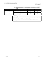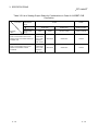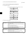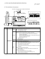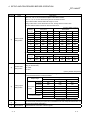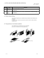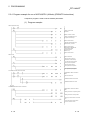
1
Digital-Analog Converter Module Digital-Analog Converter Module User's Manual User's Manual MODEL CL2DA-U-SY-E MODEL CODE 13JP31 SH(NA)-080418E-A(0501)MEE HEAD OFFICE : 1-8-12, OFFICE TOWER Z 14F HARUMI CHUO-KU 104-6212,JAPAN NAGOYA WORKS : 1-14 , YADA-MINAMI 5-CHOME , HIGASHI-KU, NAGOYA , JAPAN When exported from Japan, this manual does not require application to the Ministry of Economy, Trade and Industry for service transaction permission. Specifications subject to change without notice. CL2DA2-B BL SAFETY PRECAUTIONS (Always read these precautions before using this equipment.) Before using this product, please read this manual and the relevant manuals introduced in this manual carefully and pay full attention to safety to handle the product correctly. The precautions given in this manual are concerned with this product. Refer to the user’s manual of the CPU module to use for a description of the PLC system safety precautions. In this manual, the safety precautions are ranked as "DANGER" and "CAUTION". DANGER Indicates that incorrect handling may cause hazardous conditions, resulting in death or severe injury. ! CAUTION Indicates that incorrect handling may cause hazardous conditions, resulting in medium or slight personal injury or physical damage. ! Note that the ! CAUTION level may lead to a serious consequence according to the circumstances. Always follow the precautions of both levels because they are important to personal safety. Please save this manual to make it accessible when required and always forward it to the end user. [Design Precautions] ! DANGER When there are communication problems with the data link, the data for the master module will be held. Configure an interlocking circuit in a sequence program so that the safety of the overall system is always maintained. Otherwise, erroneous output and malfunction may result in accidents. ! CAUTION Do not bunch the control wires or communication cables with the main circuit or power wires, and do not install them close to each other. Keep a distance of 100mm (3.9inch) or more from each other. Not doing so could result in noise that would cause erroneous operation. At power ON/OFF, voltage or current may instantaneously be output from the output terminal of this module. In such case, wait until the analog output becomes stable to start controlling the external device. A-1 A-1 [Installation Precautions] ! CAUTION Use the PLC in the environment that meets the general specifications contained in this Manual. Using the PLC outside the range of the general specifications may result in electric shock, fire or malfunction, or may damage or degrade the module. Do not directly touch the module's conductive parts or electronic components. Doing so may cause malfunctions or failure of the module. Securely fix the module to a DIN rail or with mounting screws, and securely tighten the mounting screws within the specified torque range. Undertightening can cause a drop or malfunction. Overtightening can cause a drop or malfunction due to damage of the screws or module. [Wiring Precautions] ! DANGER Be sure to shut off all phases of the external power supply used by the system before installation or wiring. Not completely turning off all power could result in electric shock or damage to the product. ! CAUTION Terminal screws which are not to be used must be tightened always. Otherwise there will be a danger of short circuit against the bare solderless terminals. Wire the module correctly after confirming the rated voltage and terminal layout of the product. Not doing so can cause a fire or failure. Tighten the terminal screws within the specified torque range. Undertightening can cause a short circuit or malfunction. Overtightening can cause a short circuit or malfunction due to damage of the screws or module. Ensure that no foreign matter such as chips and wire-offcuts enter the module. Foreign matter can cause a fire, failure or malfunction. A-2 A-2 [Starting and Maintenance Precautions] ! DANGER Do not touch the terminals while power is on. Doing so could cause shock or erroneous operation. Be sure to shut off all phases of the external power supply used by the system before cleaning or retightening the terminal screws. Not doing so can cause the module to fail or malfunction. ! CAUTION Never disassemble or modify the module. This may cause breakdowns, malfunctioning, injury and/or fire. Do not drop the module or give it hard impact since its case is made of resin. Doing so can damage the module. Be sure to shut off all phases of the external power supply used by the system before mounting or dismounting the module to or from the panel. Not doing so can cause the module to fail or malfunction. Before handling the module, always touch grounded metal, etc. to discharge static electricity from the human body. Failure to do so can cause the module to fail or malfunction. [Disposal Precautions] ! CAUTION When disposing of this product, treat it as industrial waste. A-3 A-3 REVISIONS The manual number is given on the bottom left of the back cover. Print Date Jan., 2005 Manual Number SH(NA)-080418E-A Revision First edition Japanese Manual Version SH-080416-A This manual confers no industrial property rights or any rights of any other kind, nor does it confer any patent licenses. Mitsubishi Electric Corporation cannot be held responsible for any problems involving industrial property rights which may occur as a result of using the contents noted in this manual. 2004 MITSUBISHI ELECTRIC CORPORATION A-4 A-4 INTRODUCTION Thank you for purchasing the CC-Link/LT system remote module. Before using the equipment, please read this manual carefully to develop full familiarity with the functions and performance of the CC-Link/LT system remote module you have purchased, so as to ensure correct use. CONTENTS SAFETY PRECAUTIONS...............................................................................................................................A- 1 REVISIONS .....................................................................................................................................................A- 4 INTRODUCTION.............................................................................................................................................A- 5 About Manuals ................................................................................................................................................A- 7 Compliance with the EMC Directive and the Low Voltage Directive .............................................................A- 7 About the Generic Terms and Abbreviations .................................................................................................A- 8 Packing List .....................................................................................................................................................A- 8 1. OVERVIEW 1- 1 to 1- 2 1.1 Features ................................................................................................................................................... 1- 1 2. SYSTEM CONFIGURATION 2- 1 to 2- 4 2.1 Overall Configuration ............................................................................................................................... 2- 1 2.2 Applicable Module.................................................................................................................................... 2- 3 2.3 Notes on the System Configuration......................................................................................................... 2- 3 3. SPECIFICATIONS 3- 1 to 3-15 3.1 General Specifications ............................................................................................................................. 3- 1 3.2 Performance Specifications ..................................................................................................................... 3- 2 3.3 I/O Conversion Characteristics................................................................................................................ 3- 4 3.3.1 Voltage output characteristics........................................................................................................... 3- 5 3.3.2 Current output characteristics ........................................................................................................... 3- 6 3.3.3 Accuracy............................................................................................................................................ 3- 7 3.3.4 Conversion speed ............................................................................................................................. 3- 9 3.3.5 Output response time of remote station ........................................................................................... 3- 9 3.4 Function.................................................................................................................................................... 3-10 3.4.1 Combinations of various functions.................................................................................................... 3-11 3.5 Remote I/O Signal.................................................................................................................................... 3-13 3.5.1 Remote I/O signal list ........................................................................................................................ 3-13 3.5.2 Functions of the remote I/O signals.................................................................................................. 3-15 4. SETUP AND PROCEDURES BEFORE OPERATION 4- 1 to 4- 9 4.1 Pre-operation Procedure ......................................................................................................................... 44.2 Precautions when Handling..................................................................................................................... 44.3 Part Identification Nomenclature ............................................................................................................. 44.4 Station Number Setting............................................................................................................................ 44.5 Facing Direction of the Module Installation ............................................................................................. 4A-5 A-5 1 1 3 5 5 4.6 Wiring of Connection Cable ..................................................................................................................... 44.7 Wiring........................................................................................................................................................ 44.7.1 Wiring precautions............................................................................................................................. 44.7.2 Wiring of module with external equipment ....................................................................................... 44.8 Check of Wiring........................................................................................................................................ 44.9 Maintenance and Inspection.................................................................................................................... 45. PROGRAMMING 6 7 7 8 9 9 5- 1 to 5-19 5.1 Precautions on Programming .................................................................................................................. 5- 1 5.2 Conditions of Program Examples (when connected to QJ61CL12) ...................................................... 5- 2 5.3 Conditions of Program Examples (when connected to AJ65SBT-CLB) ................................................ 5- 6 5.3.1 Program example for use of QCPU (Q Mode) ................................................................................. 5-11 5.3.2 Program example for use of QnACPU ............................................................................................. 5-13 5.3.3 Program example for use of ACPU/QCPU (A Mode) (dedicated instructions)............................... 5-15 5.3.4 Program example for use of ACPU/QCPU (A Mode) (FROM/TO instructions).............................. 5-18 6. TROUBLESHOOTING 6- 1 to 6- 4 6.1 Using the LED Indications to Check Errors............................................................................................. 6- 1 6.2 When an Analog Output Value Is Not Output ......................................................................................... 6- 4 APPENDIX App- 1 to App- 2 Appendix 1 External Dimensions..............................................................................................................APP- 1 INDEX A-6 Index- 1 to Index- 2 A-6 About Manuals The following manuals are related to this product. Referring to this list, please request the necessary manuals. Relevant Manuals Manual Name CC-Link/LT Master Module User's Manual QJ61CL12 Explains the system configuration, performance specifications, functions, handling, wiring and troubleshooting of the QJ61CL12. (Sold separately) CC-Link - CC-Link/LT Bridge Module Type AJ65SBT-CLB User's Manual Explains the system configuration, performance specifications, functions, handling, wiring and troubleshooting of the AJ65SBT-CLB. (Sold separately) Manual Number (Model Code) SH-080351E (13JR62) SH-080362E (13JR63) Compliance with the EMC Directive and the Low Voltage Directive For details on making Mitsubishi PLC conform to the EMC directive and low voltage instruction when installing it in your product, please see Chapter 3, "EMC Directive and Low Voltage Instruction" of the User's Manual (Hardware) of the CPU module to use. The CE logo is printed on the rating plate on the main body of the PLC that conforms to the EMC directive and low voltage instruction. By making this product conform to the EMC directive and low voltage instruction, it is not necessary to make those steps individually. A-7 A-7 About the Generic Terms and Abbreviations Unless otherwise specified, the following generic terms and abbreviations are used in this manual to describe Type CL2DA2-B digital-analog converter module. Generic Term/Abbreviation CL2DA2-B QJ61CL12 AJ65SBT-CLB CC-Link/LT master module CC-Link master module Remote I/O station Remote device station Remote station Remote I/O module Remote device module Remote module QCPU (Q mode) QCPU (A mode) GX Developer Dedicated power supply Power supply adapter Description Abbreviation for type CL2DA2-B digital-analog converter module. Abbreviation for type QJ61CL12 CC-Link/LT master module. Abbreviation for type AJ65SBT-CLB CC-Link - CC-Link/LT bridge module. Generic term for QJ61CL12 when they are used as master stations. Generic term for QJ61BT11N, QJ61BT11, AJ61BT11, A1SJ61BT11, AJ61QBT11, A1SJ61QBT11 and A80BDE-J61BT11 when they are used as master stations. Remote station that handles bit information only. (inputs/outputs data to/from external devices.) Remote station that handles bit unit and word unit data only. (Performs input and output with external devices, and analog data exchange.) Generic term for remote I/O station and remote device station. Remote module that handles bit unit data only. (Performs input and output with external devices.) Remote module that handles bit unit and word unit data only. (Performs input and output with external devices, and analog data exchange.) Generic term for remote I/O module and remote device module. Generic term for Q00JCPU, Q00CPU, Q01CPU, Q02CPU, Q02HCPU, Q06HCPU, Q12HCPU, Q25HCPU, Q12PHCPU, Q25PHCPU, Q12PRHCPU and Q25PRHCPU Generic term for Q02CPU-A, Q02HCPU-A, Q06HCPU-A Generic product name of the product types SWnD5C-GPPW, SWnD5C-GPPW-A, SWnD5C-GPPW-V and SWnD5C-GPPW-VA. (n in the type indicates 4 or more.) Module connected for power supply to CC-Link/LT system. At least one power supply adapter is required for a system. Packing List The following gives the packing list of the CL2DA2-B. Product name CL2DA2-B A-8 Quantity 1 A-8 1 OVERVIEW CC-Link/LT 1 OVERVIEW This user's manual explains the specifications, handling, programming methods and others of Type CL2DA2-B digital-analog converter module (hereafter abbreviated to the "CL2DA2-B") which is used as a remote device station of a CC-Link/LT system. The CL2DA2-B is a module designed to convert digital values (15-bit signed BIN data) into analog values (voltages or currents). 1.1 Features This section gives the features of the CL2DA2-B. (1) Smaller than CC-Link D/A converter module Being the same size as the terminal block type CC-Link/LT remote I/O module (CL2X8-D1B2, CL2Y8-TP1B2), the CL2DA2-B is 55.7% less in volume than the CC-Link D/A converter module (AJ65SBT-62DA). (2) Output range selectable per channel You can choose the analog output range per channel to change the I/O conversion characteristics. (3) Analog output hold/clear setting for communication cutoff It can be specified whether the analog value output from each channel immediately before D/A conversion stops due to the cutoff of communication with the CC-Link/LT master module or AJ65SBT-CLB will be held or cleared. (4) Number of occupied I/O points (number of occupied stations) changeable The number of occupied I/O points (number of occupied stations) can be saved since it changes depending on the last conversion-enabled channel. When only Channel 1 is enabled for conversion, the number of occupied I/O points is 16 points (one station occupied). (5) Improved operability and maintainability The station number setting switches, HOLD/CLEAR setting switch and analog output setting switches are placed on the module front to improve operability and maintainability. (6) Simple dustproof shape for improved reliability Without radiating fins, etc., the casing has a simple dustproof shape to prevent the ingress of wire cuttings, dust and others into the module, improving reliability. (7) Six facing directions available for module installation The CL2DA2-B can be installed in any of six different orientations using a DIN rail or module installation screws. (There are no restrictions on the facing directions. see section 4.5.) 1-1 1-1 1 1 OVERVIEW CC-Link/LT MEMO 1 1-2 1-2 2 SYSTEM CONFIGURATION CC-Link/LT 2 SYSTEM CONFIGURATION This chapter describes the system configuration for use of the CL2DA2-B. 2.1 Overall Configuration 2 The overall configuration for use of the CL2DA2-B is shown below. (1) When connected to the CC-Link/LT master module CC-Link/LT master module Terminating resistor Power supply adapter CL1PAD 1 General power supply 24V DC Terminating resistor Partner company's product CC-Link/LT remote I/O module CL1Y4-T 1B2 CL2DA2-B CL2DA2 -B Y0 . 2-1 2-1 2 SYSTEM CONFIGURATION CC-Link/LT (2) When connected to the AJ65SBT-CLB CC-Link master module 2 CC-Link remote I/O module AJ65SBT-CLB CC-Link remote I/O module Terminating resistor CC-Link side CC-Link/LT side General power supply Power supply adapter 24V DC Terminating resistor CC-Link/LT remote I/O module Partner company's product CL1Y4-T 1B2 CL2DA2-B CL2DA2-B Y0 2-2 2-2 2 SYSTEM CONFIGURATION CC-Link/LT 2.2 Applicable Module The following modules can be used with the CL2DA2-B. • QJ61CL12 • AJ65SBT-CLB 2.3 Notes on the System Configuration This section explains the notes on the system configuration for use of the CL2DA2-B. (1) Point mode setting Set the point mode of the CC-Link/LT master module or AJ65SBT-CLB to the 16point mode. Any other mode setting will result in an error, causing the CC-Link/LT master module or AJ65SBT-CLB to turn on (flash if all stations are faulty) the "L ERR." LED, and the CL2DA2-B to turn off the "L RUN" LED and turn on the "L ERR." LED. Using a remote module of less than 16 occupied I/O points in the 16-point mode will produce unassigned points. For the concept of the point mode setting and occupied I/O point setting, refer to the user's manual of the used CC-Link/LT master module or AJ65SBT-CLB. (2) Maximum number of connected stations The CL2DA2-B can be connected within the occupied I/O point range of the CCLink/LT master module or AJ65SBT-CLB. The maximum number of connected modules varies depending on the number of occupied I/O points (number of occupied stations) of the CL2DA2-B. Refer to Section 3.4 for the number of occupied I/O points (number of occupied stations). (a) Maximum number of modules when connected to CC-Link/LT master module Number of occupied I/O points of 16 32 48 64 128 256 512 1024 CC-Link/LT master module points points points points points points points points 1 2 3 4 8 16 32 64 1 1 2 4 8 16 32 Number of occupied I/O 16 points points of CL2DA2-B (Occupies 1 station) (Number of occupied 32 points stations) (Occupies 2 stations) 2-3 2-3 2 SYSTEM CONFIGURATION CC-Link/LT (b) Maximum number of modules when connected to AJ65SBTCLB Number of occupied I/O points of AJ65SBT-CLB Number of occupied I/O 16 points points of CL2DA2-B (Occupies 1 station) (Number of occupied 32 points stations) (Occupies 2 stations) 48 points 112 points 224 points 3 7 14 1 3 7 POINT The maximum number of connected modules changes depending on the capacity of the dedicated power supply or power supply adaptor. For details, refer to the user's manual of the dedicated power supply or power supply adaptor. 2-4 2-4 3 SPECIFICATIONS CC-Link/LT 3 SPECIFICATIONS This chapter provides the specifications of the CL2DA2-B. 3.1 General Specifications Table 3.1 indicates general specifications of the CL2DA2-B. Table 3.1 General Specifications Item Specifications Operating ambient 0 to 55°C temperature Storage ambient -25 to 75°C temperature Operating ambient 5 to 95%RH, non-condensing humidity Storage ambient 5 to 95%RH, non-condensing humidity Conforming Vibration resistance to JIS B 3502, IEC 61131-2 Under intermittent vibration Under continuous vibration Shock resistance Operating ambience Operating altitude Installation location Overvoltage category Frequency Acceleration 10 to 57Hz ——— 57 to 150Hz 9.8m/s 10 to 57Hz ——— 57 to 150Hz 4.9m/s Amplitude Sweep count 0.075mm (0.003in.) 2 ——— 0.035mm (0.001in.) 2 10 times each in X, Y, Z directions (for 80 min.) ——— 2 Conforming to JIS B 3502, IEC 61131-2 (147 m/s , 3 times in each of 3 directions X, Y, Z) No corrosive gases Less than 2000m (6562ft.) Inside control panel 1 2 Less than II 3 Pollution level 3 4 Less than 2 1 : The equipment cannot be used under pressure higher than the atmospheric pressure of altitude 0m. Doing so can cause a failure. 2 : It can also be used in an environment other than on the control panel if the conditions such as operating ambient temperature and humidity are satisfied. 3 : This indicates the section of the power supply to which the equipment is assumed to be connected between the public electrical power distribution network and the machinery within premises. Category II applies to equipment for which electrical power is supplied from fixed facilities. The surge withstand voltage level for up to the rated voltage of 300 V is 2500 V. 4 : This index indicates the degree to which conductive material is generated in terms of the environment in which the equipment is used. Pollution level 2 means that only non-conductive pollution occurs. A temporary conductivity caused by condensing must be expected occasionally. 3-1 3-1 3 SPECIFICATIONS CC-Link/LT 3.2 Performance Specifications Table 3.2 indicates performance specifications of the CL2DA2-B. Table 3.2 Performance Specifications Item Specification Voltage Digital input Analog output 15-bit signed binary (-4096 to 4095) Current 15-bit signed binary (-96 to 4095) Voltage -10 to 10V DC (input resistance: 1k to 1M ) Current 0 to 20mA DC (external load resistance: 0 to 600 ) 3 Accuracy Analog output range I/O characteristics, maximum resolution, accuracy (accuracy relative to maximum value of analog output value) Digital input value 25±5°C -10 to 10V Voltage ±0.2% (±20mV) ±0.4% (±40mV) 0 to 4000 ±0.2% (±10mV) ±0.4% (±20mV) ±0.2% (±40µA) ±0.4% (±80µA) 0 to 10V 0 to 5V Current 0 to 20mA 4 to 20mA 1 Ambient temperature 0 to 55°C -4000 to 4000 1 to 5V 0 to 4000 Conversion speed Temperature coefficient 2 Max. resolution 2.5mV ±80ppm/°C (±0.0080%/°C) 1.25mV 1.0mV 5µA 4µA 200µs/2 channels Output short-circuit protection Yes Absolute maximum output Voltage : ±12 V, current : +21mA Number of analog output point 2 channels/1module CC-Link/LT station type Remote device station Number of occupied stations 2 stations in 16-point mode Specific isolated area Between communication system and analog outputs Isolation specifications Ambient temperature Between power supply system and analog outputs Isolation method Photocoupler isolation Transformer isolation 3 Dielectric withstand voltage 500V AC for 1 minute Insulation resistance 500V DC 10M or more Between communication system and power supply line Between channels Connected terminal block Applicable wire size Applicable crimping terminal Module installation method Applicable DIN rail Voltage Module power supply 4 Protection class Weight 3-2 No insulation — — Direct type 14-point terminal block (M3 screw) 0.3 to 1.25mm2 RAV1.25-3 (in conformance with JIS C 2805), V1.25-3 (Japan Solderless Terminal Mfg. Co., Ltd.), 1.25-3, TG1.25-3(NICHIFU TERMINAL INDUSTRIES Co., Ltd.) DIN rail installation, mounted by screws of type M4 0.7 mm Can be installed in six directions 16 mm or larger TH35-7.5Fe, TH35-7.5Al, (in conformance with IEC 60715) 24V DC (20.4V DC to 28.8V DC, ripple ratio: within 5%) Current consumption 170mA Current on startup 470mA IP2X 0.15kg 3-2 3 SPECIFICATIONS CC-Link/LT 1: Reference accuracy. (see section 3.3.3) 2: Accuracy per temperature change of 1°C. (see section 3.3.3) 3: The number of occupied I/O points (number of occupied stations) changes depending on the last channel enabled for conversion. (see section 3.4) 4: Supplied by the dedicated power supply or power supply adaptor. 3-3 3-3 3 SPECIFICATIONS CC-Link/LT 3.3 I/O Conversion Characteristics An I/O conversion characteristic indicates an inclination of a straight line which connects an offset value and a gain value at the time when a digital value set from the PLC CPU is converted into an analog value (voltage or current output). The offset value is an analog value (voltage or current) output when the digital value set from the PLC CPU is 0. The gain value is an analog value (voltage or current) output when the digital value set from the PLC CPU is 4000. 3-4 3-4 3 SPECIFICATIONS CC-Link/LT 3.3.1 Voltage output characteristics The voltage output characteristic graph is shown below. 1) Analog output value (V) 5 3) 1 2) 0 -5 Practical analog output scope 10 -10 -4096 -4000 -96 0 -2000 2000 4000 4095 Digital input value Number 1) 2) 3) Analog Output Range Setting -10 to 10V 0 to 10V 0 to 5V 1 to 5V Offset Value Gain Value 0V 10V 0V 1V 5V 5V Digital Input Value -4000 to 4000 Maximum Resolution 0 to 4000 1.25mV 1.0mV 2.5mV Fig. 3.1 Voltage Output Characteristic POINT Within the digital input and analog output scopes of each output range, the maximum resolution and accuracy are within the performance specification range. Outside those scopes, however, they may not fall within the performance specification range. (Avoid using the dotted line part in Fig. 3.1.) 3-5 3-5 3 SPECIFICATIONS CC-Link/LT 3.3.2 Current output characteristics The current output characteristic graph is shown below. Practical analog output scope 20 Analog output value (mA) 15 10 2) 1) 5 4 0 -96 0 2000 4000 4095 Digital input value Number 1) 2) Analog Output Range Setting 0 to 20mA 4 to 20mA Offset Value 0mA 4mA Gain Value 20mA 20mA Digital Input Value 0 to 4000 Maximum Resolution 5µA 4µA Fig. 3.2 Current Output Characteristic POINT Within the digital input and analog output scopes of each output range, the maximum resolution and accuracy are within the performance specification range. Outside those scopes, however, they may not fall within the performance specification range. (Avoid using the dotted line part in Fig. 3.2.) 3-6 3-6 3 SPECIFICATIONS CC-Link/LT 3.3.3 Accuracy Accuracy is relative to the maximum value of the analog output value. If you change the output range to change the output characteristic, accuracy does not change and is held within the range indicated in the performance specifications. Calculate the accuracy in the following method. (Accuracy) = (Reference accuracy) + (Temperature coefficient) (Operating ambient temperature change) Reference accuracy: Accuracy when the operating ambient temperature is 25±5°C(±0.2%) Temperature coefficient: Accuracy for every 1°C change in temperature (±80ppm/°C (±0.0080%/°C)) Operating ambient temperature change: Difference between the operating ambient temperature outside the range 25±5°C and the minimum/maximum range value Example) Accuracy when the operating ambient temperature is 35°C (±0.2%) + (±0.0080%/°C) (35°C-30°C) = ±0.24% (1) Accuracy of voltage output For voltage output, the maximum value of the analog output value changes with the range. For example, accuracy is relative to 5V when the 0 to 5V range is selected. Analog output is provided at the accuracy of within ±0.2% (±10mV) when the operating ambient temperature is 25±5°C, or within ±0.4% (±20mA) when the operating ambient temperature is 0 to 55°C. 5V Analog output value Varies within the range of 0.2% ( 10 mV) at operating ambient temperature of 25 5 Varies within the range of 0.4% ( 20 mV) at operating ambient temperature of 0 to 55 . . 0V 0 4000 Digital input value Fig. 3.3 Voltage Output Accuracy (When 0 to 5V Range Is Selected) 3-7 3-7 3 SPECIFICATIONS CC-Link/LT (2) Accuracy of current output For current output, accuracy is relative to 20mA. Analog output is provided at the accuracy of within ±0.2% (±40µA) when the operating ambient temperature is 25±5°C, or within ±0.4% (±80µA) when the operating ambient temperature is 0 to 55°C. 20mA Analog output value Varies within the range of 0.2% ( 40 A) at operating ambient temperature of 25 5 Varies within the range of 0.4% ( 80 A) at operating ambient temperature of 0 to 55 . . 0mA 0 4000 Digital input value Fig. 3.4 Current Output Accuracy 3-8 3-8 3 SPECIFICATIONS CC-Link/LT 3.3.4 Conversion speed The conversion speed of the CL2DA2-B is fixed to 200µs independently of the number of conversion-enabled channels. 3.3.5 Output response time of remote station This section explains the remote station output response time of the CL2DA2-B. The remote station output response time is used in the calculation of the transmission delay time. The remote station output response time of the CL2DA2-B is 0.4ms including the internal processing time. 0.2ms (conversion speed) 2 = 0.4ms [Transmission delay time] The transmission delay time is the time from when the set digital value written to the device (Y) of the PLC CPU is read until an analog value is output after digital-to-analog conversion. For how to calculate the link scan time, refer to the user's manual of the CC-Link/LT master module or AJ65SBT-CLB. SM +LS 2 + Output response time of remote station [ms] SM : Sequence program scan time of master station LS : Link scan time Example) When the module is connected to the QJ61CL12, the transmission speed is 625kbps, the last station No. is 10, the sequence scan time of the master station is 5ms, the link scan time is 1.2ms, and the output response time of the remote station is 0.4ms =5 + 1.2 =7.8ms 3-9 2 + 0.4 3-9 3 SPECIFICATIONS CC-Link/LT 3.4 Function The CL2DA2-B function list is shown in table 3.3. Table 3.3 CL2DA2-B Function List Item Description Reference Section D/A conversion enable/disable function (1) Specifies whether to enable or disable the D/A conversion for each channel. (2) The number of occupied I/O points (number of occupied stations) changes depending on the last channel enabled for conversion. For example, when only Channel 2 is enabled for conversion, the number of occupied I/O points is 32 points (occupies 2 stations). (3) Set this function using the analog output setting switches. (see section 4.3) — D/A output enable/disable function (1) Whether the output of the D/A conversion value is enabled or disabled can be specified for each channel. (2) Set this function using the CH output enable/disable flag (YnF). (see section 3.5.2) — Output range changing function (1) Can set the analog output range per channel to change the I/O conversion characteristics. (2) Set this function using the analog output setting switches. (see section 4.3) — Communication cutoff-time analog output hold/clear function (HOLD/CLEAR setting) (1) It can be specified whether the analog value output from each channel immediately before D/A conversion stops due to the cutoff of communication with the CC-Link/LT master module or AJ65SBT-CLB will be held or cleared. (2) Set this function for all channels at once using the HOLD/CLEAR setting switch. (see section 4.3) 3 - 10 Section 3.4.1 3 - 10 3 SPECIFICATIONS CC-Link/LT 3.4.1 Combinations of various functions The analog output can be set as indicated in Table 3.4 and Table 3.5 by the combination of the D/A conversion enable/disable setting (analog output setting switches), CH output enable/disable flag (YnF) and HOLD/CLEAR setting (HOLD/CLEAR setting switch). Make setting according to your application. Table 3.4 List of Analog Output Status by Combinations in Case of CC-Link/LT Master Module Connection Setting combination D/A conversion enable/disable setting CH output enable/disable flag Execution status HOLD/CLEAR setting Enable Enable (ON) HOLD CLEAR Disable Disable (OFF) Enable or disable HOLD or CLEAR HOLD or CLEAR Analog output status when the PLC CPU is in the RUN status Output of the analog value after D/A conversion from the digital value specified by the PLC CPU Offset value 0V/0mA Analog output status when the PLC CPU is in the STOP status Offset value (Not held) Offset value 0V/0mA Offset value 0V/0mA Analog output status at PLC CPU stop error The analog value before the "L RUN" LED turns OFF is held. Analog output status when a digital value setting error occurred Output of the maximum or minimum analog value Offset value 0V/0mA Analog output status when a timeout error occurred The analog value before the "L RUN" LED turns OFF is held. Offset value Offset value 0V/0mA Analog output status when a communication data error occurred The analog value converted from the digital value set from the PLC CPU during normal communication is output. Offset value 0V/0mA 0V/0mA 0V/0mA Offset value 0V/0mA 0V/0mA 0V/0mA Analog output status when a setting switch error (station number setting, analog output setting switches) or point mode setting error occurred Analog output status when "L ERR." LED flickers at fixed intervals (0.4s intervals) Analog output status when a watchdog timer error occurred 3 - 11 0V/0mA Offset value 0V/0mA Output of the analog value after D/A conversion from the digital value specified by the PLC CPU 0V/0mA 0V/0mA 3 - 11 3 SPECIFICATIONS CC-Link/LT Table 3.5 List of Analog Output Status by Combinations in Case of AJ65SBT-CLB Connection Setting combination D/A conversion enable/disable setting CH output enable/disable flag Execution status HOLD/CLEAR setting Enable Enable (ON) HOLD Disable Disable (OFF) Enable or disable CLEAR HOLD or CLEAR HOLD or CLEAR When a communication error occurs between the CC-Link master station and AJ65SBT-CLB The analog value before the "L RUN" LED turns OFF is held. Offset value Offset value 0V/0mA When a communication error occurs between the AJ65SBT-CLB and CL2DA2-B The analog value before the "L RUN" LED turns OFF is held. Offset value Offset value 0V/0mA 3 - 12 3 - 12 3 SPECIFICATIONS CC-Link/LT 3.5 Remote I/O Signal This section describes the assignment and functions of the remote I/O signals. 3.5.1 Remote I/O signal list The remote input (X) means the input signal from the CL2DA2-B to the CC-link/LT master module or AJ65SBT-CLB, and the remote output (Y) means the output signal from the CC-link/LT master module or AJ65SBT-CLB to the CL2DA2-B. The numbers of remote input (X) and remote output (Y) points change depending on the number of occupied CL2DA2-B stations. When occupies 1 station : X00 to X0F, Y00 to Y0F When occupies 2 stations : X00 to X1F, Y00 to Y1F The remote I/O numbers (X/Y) change depending on the following conditions. When connected to CC-Link/LT master module • Start I/O numbers of CC-Link/LT master module • Station number of CL2DA2-B When connected to AJ65SBT-CLB • Station number of AJ65SBT-CLB • Station number of CL2DA2-B The remote I/O numbers (X/Y) in this chapter and later are indicated under the following conditions. • Start I/O number of CC-Link/LT master module: 0 • Station number of CL2DA2-B: 1 Table 3.6 indicates the assignment and names of the remote I/O signals. 3 - 13 3 - 13 3 SPECIFICATIONS CC-Link/LT Table 3.6 Remote I/O Signals List Signal direction: CL2DA2-B Signal direction: CC-Link/LT master module/ CC-Link/LT master module/AJ65SBT-CLB Remote Remote Signal name input(X) CL2DA2-B AJ65SBT-CLB Remote I/O point Signal name output(Y) Y00 CH1 digital value setting to 16 points Y0E (Occupies 1 station) Y0F CH1 output enable/disable flag X00 to Use prohibited Y10 X1F to CH2 digital value setting Y1E 32 points (Occupies 2 stations) Y1F CH2 output enable/disable flag POINT The reserved devices given in Table 3.6 are used by the system and cannot be used by the user. REMARK When the CL2DA2-B is connected to the QJ61CL12, the following information is stored in the detailed remote station information area (buffer memory address 32 to 95: Un\G32 to Un\G95). b15 b14 b13 b12 b11 b10 b9 0 0 0 0 Vacant 0 0 0 b8 b7 b6 b5 b4 b3 b2 b1 b0 0/1 0 0/1 1 1 1 1 0 0 I/O points : 16pts. Output flag*1 : Output identified Input flag*1 : Input identified Remote device station flag : Remote device station First station flag*2 0: Not first station 1: First staion Input filter setting : No setting Clear of output / hold setting*3 0: Clear 1: Hold *1 In the case of the CL2DA2-B, 11 are stored to be, b4. *2 For a module that has 2 occupied stations, only the bit of the first station will turn on. *3 This depends on the setting of the HOLD/CLEAR setting switch on the CL2DA2-B. 3 - 14 3 - 14 3 SPECIFICATIONS CC-Link/LT 3.5.2 Functions of the remote I/O signals Table 3.7 explains the functions of the remote I/O signals of the CL2DA2-B. "n" in the table is determined by the channel, starting I/O number and station number. Table 3.7 Remote I/O Signal Details Device No. Signal Name Description (1) This area is used to write digital values for performing D/A conversion from the PLC CPU as 15-bit signed binary code. YnF YnE YnDYnC YnB YnA Yn9 Yn8 Yn7 Yn6 Yn5 Yn4 Yn3 Yn2 Yn1 Yn0 CH CH Yn0 to YnE CH digital value setting digital value setting output enable/disable flag (2) When the digital value setting is outside the valid range, D/A conversion will be performed as described below. Output range setting Valid range (practical range) Digital value that is set when a value outside the valid range is written -10 to 10V -4096 to 4095 (practical range: -4000 to 4000) 4096 or larger: 4095 -4097 or smaller: -4096 -96 to 4095 (practical range: 0 to 4000) 4096 or larger: 4095 -97 or smaller: -96 4 to 20mA 0 to 20mA 1 to 5V 0 to 5V 0 to 10V XnF 3 - 15 CH flag output enable/disable (1) Set whether the output of the D/A conversion value is enabled or disabled for each channel. ON: output enable OFF: output disable 3 - 15 4 SETUP AND PROCEDURES BEFORE OPERATION CC-Link/LT 4 SETUP AND PROCEDURES BEFORE OPERATION 4.1 Pre-operation Procedure This section explains the preparatory procedure for operating the CL2DA2-B. START Switch setting (See section 4.3) Set the station number setting switches. Set the HOLD/CLEAR setting switch. Set the analog output setting switches. Wiring Wiring of connection cable (See section 4.6) Wiring of module with external equipment (See section 4.7) 4 Create a program (See Chapter 5) Start data link END 4.2 Precautions when Handling The precautions when handling the CL2DA2-B are described below: ! DANGER Be sure to shut off all phases of the external power supply used by the system before installation or wiring. Not completely turning off all power could result in electric shock or damage to the product. Do not touch the terminals while power is on. Doing so could cause shock or erroneous operation. Be sure to shut off all phases of the external power supply used by the system before cleaning or retightening the terminal screws. Not doing so can cause the module to fail or malfunction. ! CAUTION Ensure that no foreign matter such as chips and wire-offcuts enter the module. Foreign matter can cause a fire, failure or malfunction. Never disassemble or modify the module. This may cause breakdowns, malfunctioning, injury and/or fire. Do not directly touch the module's conductive parts or electronic components. Doing so may cause malfunctions or failure of the module. 4-1 4-1 4 SETUP AND PROCEDURES BEFORE OPERATION ! CAUTION CC-Link/LT When disposing of this product, treat it as industrial waste. Use the PLC in the environment that meets the general specifications contained in this Manual. Using the PLC outside the range of the general specifications may result in electric shock, fire or malfunction, or may damage or degrade the module. Securely fix the module to a DIN rail or with mounting screws, and securely tighten the mounting screws within the specified torque range. Undertightening can cause a drop or malfunction. Overtightening can cause a drop or malfunction due to damage of the screws or module. Be sure to shut off all phases of the external power supply used by the system before mounting or dismounting the module to or from the panel. Not doing so can cause the module to fail or malfunction. Before handling the module, always touch grounded metal, etc. to discharge static electricity from the human body. Failure to do so can cause the module to fail or malfunction. 4 (1) Tighten the terminal screws for the module to the specified torque shown below. Screw location Clamping torque range Module mounting screw (M4 screw) Terminal block terminal screw (M3 screw) 78 to 108 N cm 42 to 58 N cm (2) When using a DIN rail, attach the DIN rail after taking the following items into consideration: (a) Applicable DIN rail types (conform to IEC 60715) TH35-7.5Fe TH35-7.5Al (b) Interval between the DIN rail's installation screws Tighten the screws using a pitch of 200mm (7.87in.) or less when attaching a DIN rail. (3) To attach the CL2DA2-B to the DIN rail, press the centerline area of the DIN rail hook beneath the module until a click is heard. (4) Maintain some distance between the module and other components and parts, 10 mm (0.39in.) from the top and 60 mm (2.36in.) from the bottom of the module, in order to improve ventilation and to make replacement of the module easy if a CL2DA2-B is installed on a board. (5) Install the CL2DA2-B on a level surface. If the surface is uneven, unnecessary force is applied to the printed circuit board, causing malfunctions. 4-2 4-2 4 SETUP AND PROCEDURES BEFORE OPERATION CC-Link/LT 4.3 Part Identification Nomenclature The name of each part in the CL2DA2-B is listed below. 9)* * The connector is not supplied. Prepare a connector for dedicated flat cable. 8) 2) 3) 5) 4) STATION NO. CH1 CH2 NC HLD 402010 8 4 2 1 0 1 2 0 1 2 1 2 3 4 5 6 7 8 9 10 1 2 3 4 5 6 7 8 9 10 1) CL2DA2-B SWITCH MODE 0 1 2 OFF OFF OFF OFF OFF ON OFF ON OFF OFF ON ON ON OFF OFF ON OFF ON ON ON OFF ON ON ON FUNCTION 4 0 1 0 -10 0 20mA 20mA 5V 5V 10V 10V PW 1 2 3 RUN L RUN L ERR. 4 5 6 7 3 5 4 2 FG CH2 6) 1) 3 4 5 6 7 8 9 10 6 7 9 11 13 CH1 CH1 CH2 CH2 V+ I+ V+ I+ 8 10 12 14 COM COM 7) Description PW LED ON : Power supply on OFF : The power supply is turned off The voltage drop is too large RUN LED ON : Normal operation Flickering : When the set digital value is outside the valid range When the analog output setting switches are set to disable the conversion of all channels When the analog output setting switch or HOLD/CLEAR setting switch setting was changed during operation When the NC switch is ON OFF : Watchdog timer error Fault in hardware L RUN Operation status LED display LED L ERR. LED 4-3 1 2 Terminal numbers and signal names 1 Name 9 10 ON CH1 Number 8 STATION NO. HLD CH1 CH2 NC 402010 8 4 2 1 0 1 2 0 1 2 1 2 3 4 5 6 7 8 9 10 1 2 3 4 5 6 7 8 9 10 ON : Normal communication OFF : Communication cut off (timeout error) ON : When a communication data error occurred When the station number setting switch setting is outside the valid range When other than the 16-point mode is set Communication cut off (timeout error) When the analog output setting switches are set to disable the conversion of all channels Flickering at fixed intervals (0.4s intervals): When the station number setting switch setting was changed from the power-on setting. Flickering at unfixed intervals: When the terminating resistor was not installed When the module or connection cable is affected by noise OFF : Indicates normal communications 4-3 4 SETUP AND PROCEDURES BEFORE OPERATION Number Name CC-Link/LT Description Select "10", "20" or "40" to set the ten's place of the station number. Select "1", "2", "4" or "8" to set the one's place of the station number. Always set the station number within the range of 1 to 64. Setting of other than 1 to 64 will result in an error, turning ON the "L ERR." LED. The same station number cannot be used more than once. (Factory default: All OFF) Station 2) Ten's place One's place number 40 20 10 8 4 2 1 1 OFF OFF OFF OFF OFF OFF ON 2 OFF OFF OFF OFF OFF ON OFF Station number 3 OFF OFF OFF OFF OFF ON ON setting switch 4 OFF OFF OFF OFF ON OFF OFF : : : : : : : : 10 OFF OFF ON OFF OFF OFF OFF 11 OFF OFF ON OFF OFF OFF ON : : : : : : : : 64 ON ON OFF OFF ON OFF OFF (Example) Set the switches as below when setting the station number to 32: Station Ten's place One's place number 40 20 10 8 4 2 1 32 OFF ON ON OFF OFF ON OFF Set whether the analog value is to be held or cleared in the event of communication cutoff (one 3) HOLD/CLEAR setting switch setting for all channels). OFF: Clear ON: Hold (Factory default: OFF(Clear)) Set the D/A conversion enable/disable and output range to each channel. Set the unused channel to conversion disable. Output range 4) Analog output setting switch Setting switches 0 1 2 4 to 20mA OFF OFF OFF 0 to 20mA OFF OFF ON Conversion 1 to 5V OFF ON OFF enable 0 to 5V OFF ON ON -10 to 10V ON OFF OFF 0 to 10V ON OFF ON ON ON OFF ON ON ON Conversion disable (Factory default: All OFF (4 to 20mA)) 5) NC 6) Terminal block 4-4 Must not be used. (Used by the system and unavailable for the user. Keep this switch OFF. If it is turned ON, the RUN LED flickers.) Terminal block for connection of the I/O signals. 4-4 4 SETUP AND PROCEDURES BEFORE OPERATION Number Name 7) DIN rail hook 8) Cable guide CC-Link/LT 9) interface connector CC-Link/LT Description Used to mount the module to the DIN rail. Guide used when wiring the CC-Link/LT dedicated flat cable of the CL2DA2-B downward. (See section 4.6) Connector for connection of the CC-Link/LT communication line or module power supply (Sold separately). 4.4 Station Number Setting The remote I/O signals (X/Y) are determined by the station number setting of the CL2DA2-B. For details, refer to the user's manual of the used CC-Link/LT master module or AJ65SBT-CLB. 4.5 Facing Direction of the Module Installation The CL2DA2-B may be installed in any of six directions. (There are no restrictions on the facing directions.) Front mounting Flat mounting 4-5 Front mounting Roof mounting 4-5 4 SETUP AND PROCEDURES BEFORE OPERATION CC-Link/LT 4.6 Wiring of Connection Cable For the wiring of the connection cable for connection of the CL2DA2-B and CC-Link/LT master module/AJ65SBT-CLB, refer to the user's manual of the used CC-Link/LT master module or AJ65SBT-CLB. (1) When the CL2DA2-B is connected to the drop line of the VCTF or high flexible cable, the CC-Link/LT dedicated flat cable of the CL2DA2-B must be fabricated to 20cm (7.87in.) or less. (2) The CC-Link/LT dedicated flat cable of the CL2DA2-B can be wired downward by use of the cable guide. The permissible bending radius (r) of the CC-Link/LT dedicated flat cable of the CL2DA2-B is 15mm (0.59in.). Permissible bending radius (r) of cable: 15mm (0.59in.) Slide the cable sideways to install. 4-6 4-6 4 SETUP AND PROCEDURES BEFORE OPERATION CC-Link/LT 4.7 Wiring This section provides the precautions for wiring the CL2DA2-B and its wiring with external equipment. 4.7.1 Wiring precautions To obtain maximum performance from the functions of CL2DA2-B and improve the system reliability, an external wiring with high durability against noise is required. The precautions when performing external wiring are as follows: (1) Use separate cables for the AC and CL2DA2-B external output signals, in order not to be affected by the AC side surge or conductivity. (2) Do not bundle or place with load carrying wires other than the main circuit line, high voltage line or PLC. Noises, surges, or conductivity may affect the system. (3) Ground the shield wires or shield cables at one end on the external device side. 4-7 4-7 4 SETUP AND PROCEDURES BEFORE OPERATION CC-Link/LT 4.7.2 Wiring of module with external equipment (1) For voltage output 1 Motor drive module,etc. 1k D/A conversion CH1 to V COM 1M GND Motor drive module,etc. 1k CH2 to V COM 1M GND 1 Use a two-core twisted shield line for the power cable. (2) For current output 1 Motor drive module,etc. 0 D/A conversion CH1 I+ COM to 600 GND Motor drive module,etc. 0 CH2 I+ COM to 600 GND 1 Use a two-core twisted shield line for the power cable. 4-8 4-8 4 SETUP AND PROCEDURES BEFORE OPERATION CC-Link/LT 4.8 Check of Wiring Using the program in Chapter 5, check the wiring. 4.9 Maintenance and Inspection There are no special inspection items for the CL2DA2-B module, but follow the inspections items describes in the PLC CPU User's Manual so that the system can always be used in the best condition. 4-9 4-9 5 PROGRAMMING CC-Link/LT 5 PROGRAMMING This chapter describes the programming of the CL2DA2-B. When utilizing the program example introduced in this chapter for an actual system, fully verify that there are no problems in controllability in the target system. Refer to the user's manual of the used CC-Link/LT master module or AJ65SBT-CLB for the CC-Link/LT master module/AJ65SBT-CLB, and refer to the AnSHCPU/AnACPU/AnUCPU/QCPU-A (A Mode) Programming Manual (Dedicated Instructions) for details of the dedicated instructions. 5.1 Precautions on Programming The following explains precautions on the creation of a program: (1) CH digital value setting and CH setting output enable/disable flag For the CH digital value setting (Yn0 to YnE) and CH output enable/disable flag (YnF), create a sequence program so that the setting is stored into the word devices once and then finally written to the Y signal areas. If a program in which these data are directly written to the Y signal areas (sequence program as shown in Fig. 5.1), the Y signal (YnF) may turn OFF instantaneously. Fig. 5.1 In the following program example, the CH digital value setting (Yn0 to YnE) and CH output enable/disable flag (YnF) setting are stored into the "digital value setting, output enable/disable flag storing data registers (D11, D12)" and then are written to the Y signal areas. Fig. 5.2 5-1 5-1 5 5 PROGRAMMING CC-Link/LT 5.2 Conditions of Program Examples (when connected to QJ61CL12) The program example of Section 5.2.1 is created under the following conditions. (1) System configuration PLC CPU Master station (X/Y00 to X/Y1F) I/O (32 input points) (X20 to X3F) I/O (32 output points) (Y40 to Y5F) CL2DA2-B Terminating resistor Power supply adapter 5 CL1PAD1 General power supply 24V DC Terminating resistor (a) Master station settings Item Number of occupied I/O points setting Transmission rate setting Point mode setting Settings 32 points (X/Y00 to X/Y1F) 2.5Mbps 16-point mode Last station number setting 2 (b) CL2DA2-B settings Item Station number setting Number of occupied stations setting Station number 1 Occupies 2 stations CH1 output range setting 0 to 5V CH2 output range setting 4 to 20mA HOLD/CLEAR setting 5-2 Settings HOLD 5-2 5 PROGRAMMING CC-Link/LT (2) Device assignment to program examples The devices used in the program example of Section 5.2.1 are shown below. (a) Remote I/O (X/Y) Station No. Model Name Input X 00 1 2 CL2DA2-B (Occupies 2 stations) CL2DA2-B (Occupies 2 stations) 5-3 Output Station No. Y 00 Model Name Input X 20 Output Y 20 X 01 Y 01 X 21 Y 21 X 02 Y 02 X 22 Y 22 X 03 Y 03 X 23 Y 23 X 04 Y 04 X 24 Y 24 X 05 Y 05 X 25 Y 25 X 06 Y 06 X 26 Y 26 X 27 Y 27 X 28 Y 28 Y 09 X 29 Y 29 X 0A Y 0A X 2A Y 2A X 0B Y 0B X 2B Y 2B X 0C Y 0C X 2C Y 2C X 0D Y 0D X 2D Y 2D X 0E Y 0E X 2E Y 2E X 0F CH1 output Y 0F enable/ disable flag X 2F Y 2F X 10 Y 10 X 30 Y 30 X 11 Y 11 X 31 Y 31 X 12 Y 12 X 32 Y 32 X 13 Y 13 X 33 Y 33 X 14 Y 14 X 34 Y 34 X 15 Y 15 X 35 Y 35 X 16 Y 16 X 36 Y 36 X 37 Y 37 X 38 Y 38 Y 19 X 39 Y 39 X 1A Y 1A X 3A Y 3A X 1B Y 1B X 3B Y 3B X 1C Y 1C X 3C Y 3C X 1D Y 1D X 3D Y 3D X 1E Y 1E X 3E Y 3E X 1F CH2 output Y 1F enable/ disable flag X 3F Y 3F X 07 X 08 Use X 09 prohibited X 17 X 18 Use X 19 prohibited CH1 digital Y 07 value setting Y 08 CH2 digital Y 17 value setting Y 18 3 4 5-3 5 PROGRAMMING CC-Link/LT (b) Device used by user Device X20 Application Device Application CC-Link/LT control start signal X24 CH1 output enable signal X21 Data link stop instruction signal X25 CH2 output enable signal X22 Data link restart instruction signal Y40 Data link error confirmation signal Y42 Remote I/O error confirmation signal Y41 All station fault confirmation signal Y43 Remote station error confirmation signal M2 Control start flag D0 D1 D2 D3 5-4 Data register for reading information of operating status Data register for reading information of remote station connection Data register for reading detailed error information Data register for reading information of faulty station — — D11 D12 D13 D14 CH1 digital value setting, output enable/disable flag storing data register CH2 digital value setting, output enable/disable flag storing data register CH1 digital value setting monitoring data register CH2 digital value setting monitoring data register 5-4 5 PROGRAMMING CC-Link/LT (3) Program example CC-Link/LT data link status confirmation Reading information of operating status Reading detailed remote station information Reading detailed error information Checking for remote station connection error Control starts when remote station connection status is normal. CC-Link/LT error confirmation Checking for data link error Checking if all stations are faulty or not Checking for remote I/O error Reading information of faulty station Setting digital values, specification of output enable/disable CH1 digital value setting Storing CH1 digital value setting in the data register for monitoring. CH1 output enable CH2 digital value setting Storing CH2 digital value setting in the data register for monitoring. CH2 output enable Writing the setting to CL2DA2-B. instructing data link stop instructing data link restart 5-5 5-5 5 PROGRAMMING CC-Link/LT 5.3 Conditions of Program Examples (when connected to AJ65SBT-CLB) The program examples of Sections 5.3.1 to 5.3.4 are created under the following conditions. (1) System configuration PLC CPU Master station (X0 to X1F/Y0 to Y1F) I/O (64 input points) (X20 to X5F) I/O (64 output points) (Y60 to Y9F) AJ65SBT-CLB CL2DA2-B Terminating resistor Power supply adaptor CL1PA D1 General power supply 24V DC Terminating resistor (a) Master station settings Item Number of occupied I/O points setting Transmission rate setting 5-6 Settings 32 points (X/Y00 to X/Y1F) 156 kbps 5-6 5 PROGRAMMING CC-Link/LT (b) AJ65SBT-CLB settings Item Station number setting (CC-Link side) Number of occupied stations setting (CC-Link side) Transmission rate setting (CC-Link side) Point mode setting (CC-Link/LT side) Transmission rate setting (CC-Link/LT side) Last station number setting (CC-Link/LT side) Settings Station number 1 Occupies 4 stations 156 kbps 16-point mode 156 kbps 2 (c) CL2DA2-B settings Item Station number setting Number of occupied stations setting Station number 1 Occupies 2 stations CH1 output range setting 0 to 5V CH2 output range setting 4 to 20mA HOLD/CLEAR setting 5-7 Settings HOLD 5-7 5 PROGRAMMING CC-Link/LT (2) Device assignment to program examples The devices used in the program example of Section 5.3.1 to 5.3.4 are shown below. (a) Remote I/O (X/Y) Station No. 1 2 Model Name CL2DA2-B (Occupies 2 stations) CL2DA2-B (Occupies 2 stations) 5-8 Input Output Station No. Model Name Input Output X 400 Y 400 X 420 Y 420 X 401 Y 401 X 421 Y 421 X 402 Y 402 X 422 Y 422 X 403 Y 403 X 423 Y 423 X 404 Y 404 X 424 Y 424 X 405 Y 405 X 425 Y 425 X 406 Y 406 X 426 Y 426 X 427 Y 427 X 428 Y 428 X 407 X 408 Use X 409 prohibited CH1 digital Y 407 value setting Y 408 3 Y 409 X 429 Y 429 X 40A Y 40A X 42A Y 42A X 40B Y 40B X 42B Y 42B X 40C Y 40C X 42C Y 42C X 40D Y 40D X 42D Y 42D X 40E Y 40E X 42E Y 42E X 40F CH1 output Y 40F enable/ disable flag X 42F Y 42F X 410 Y 410 X 430 Y 430 X 411 Y 411 X 431 Y 431 X 412 Y 412 X 432 Y 432 X 413 Y 413 X 433 Y 433 X 414 Y 414 X 434 Y 434 X 415 Y 415 X 435 Y 435 X 416 Y 416 X 436 Y 436 X 437 Y 437 X 438 Y 438 X 417 X 418 Use X 419 prohibited CH2 digital Y 417 value setting Y 418 4 Y 419 X 439 Y 439 X 41A Y 41A X 43A Y 43A X 41B Y 41B X 43B Y 43B X 41C Y 41C X 43C Y 43C X 41D Y 41D X 43D Y 43D X 41E Y 41E X 43E Y 43E X 41F CH2 output Y 41F enable/ disable flag X 43F Y 43F 5-8 5 PROGRAMMING CC-Link/LT (b) Remote register (RWw) Device Remote register (RWw) D200 RWw0 Last station number setting D201 RWw1 Device D202 Remote register (RWw) RWw2 Error status flag clear Data link stop/restart — instructions (c) Remote register (RWr) Device* Remote register (RWr) D300(D456) RWr0 D301(D457) RWr1 D302(D458) Information of operating Device* Remote register (RWr) D305(D461) RWr5 Information of faulty station: D306(D462) RWr6 RWr2 station number 1 to 28 D307(D463) RWr7 D303(D459) RWr3 Remote input error D304(D460) RWr4 status Data of remote station connection Setting data — information: station number 1 to 28 In the program example (refer to Section 5.3.3) that uses the RRPA instruction (automatic refresh parameter setting) with the ACPU/QCPU (A mode), RWr0 to RWr7 are assigned to D456 to D463. (d) Devices used by user Device Application Device Application X21 Data link stop instruction signal X24 CH1 output enable signal X22 Data link restart instruction signal X25 CH2 output enable signal Y90 CC-Link side data link error confirmation signal Y93 Y91 Y92 CC-Link/LT side remote station connection error confirmation signal Y94 CC-Link/LT side all station fault confirmation signal CC-Link/LT side remote I/O error confirmation signal CC-Link/LT side data link error confirmation — signal M0 CC-Link side data link status read flag M100 CC-Link side data link normal flag M10 RLPA instruction execution flag M101 Control start flag M11 RLPA instruction normally completed flag M12 RLPA instruction abnormally completed flag M13 RRPA instruction execution flag M300 Instructing data link stop flag M20 Network parameter setting flag M315 Instructing data link restart flag D11 D12 5-9 CH1 digital value setting, output enable/disable flag storing data register CH2 digital value setting, output enable/disable flag storing data register M200 to M215 M250 to M253 D13 D14 Reading information of operating status flag Reading information of faulty station flag CH1 digital value setting monitoring data register CH2 digital value setting monitoring data register 5-9 5 PROGRAMMING CC-Link/LT (3) Relation between PLC CPU, CC-Link master station, AJ65SBTCLB and CL2DA2-B PLC CPU CC-Link master station Device X X400 to X40F X410 to X41F Address Remote input (RX) AJ65SBT-CLB Remote input (RX) E0H E1H RX00 to RX0F RX10 to RX1F RX20 to RX2F X430 to X43F E2H E3H RX00 to RX0F RX10 to RX1F RX20 to RX2F X440 to X44F X450 to X45F X460 to X46F X470 to X47F E4H E5H E6H E7H RX30 to RX3F RX40 to RX4F RX50 to RX5F RX60 to RX6F RX70 to RX7F RX30 to RX3F RX40 to RX4F RX50 to RX5F RX60 to RX6F RX70 to RX7F X420 to X42F Device Y Y400 to Y40F Y410 to Y41F Y420 to Y42F Y430 to Y43F Y440 to Y44F Y450 to Y45F Y460 to Y46F Y470 to Y47F Device D D200 D201 D202 D203 D204 D205 to D215 Device D * D300 Address Remote output (RY) 160H RY00 to RY0F 161H RY10 to RY1F 162H RY20 to RY2F System area Remote output (RY) RY00 to RY0F RY10 to RY1F Remote Address register (RWw) RY40 to RY4F RY50 to RY5F RY60 to RY6F System area RY70 to RY7F Remote register (RWw) Last station number RWw0 setting Data link stop/ RWw1 restart instructions Error RWw2 clear status flag RWw3 Use prohibited RW w0 1E1H 1E2H 1E3H 1E4H RW w1 RW w2 RW w3 RW w4 1E5H RW w5 RWw5 Use prohibited to 1EFH to RW wF RWwF Use prohibited D301 D302 2E1H RWr1 2E2H RWr2 D303 2E3H 2E4H RWr3 D304 D305 2E5H RWr5 D306 2E6H D307 2E7H RWr6 RWr7 D308 to 2E8H RWr8 to to D315 2EFH RWrF RWr4 Output Y400 to Y40F Y410 to Y41F RY30 to RY3F 1E0H Remote Address register (RWr) RWr0 2E0H Input X400 to X40F X410 to X41F RY20 to RY2F 163H RY30 to RY3F 164H RY40 to RY4F 165H RY50 to RY5F 166H RY60 to RY6F 167H RY70 to RY7F CL2DA2-B (Station No. 1) RWw4 Use prohibited to Remote register (RWr) of RWr0 Information operating status of faulty RWr1 Information station of faulty RWr2 Information station I/O error RWr3 Remote information I/O error RWr4 Remote information Data of remote RWr5 station connection of remote RWr6 Data station connection RWr7 Setting data RWr8 Use prohibited to RWrF Use prohibited In the program example (refer to Section 5.3.3) that uses the RRPA instruction (automatic refresh parameter setting) with the ACPU/QCPU (A mode), RWr0 to RWr7 are assigned to D456 to D463. POINT Depending on the CPU module, the devices used in the program examples of this chapter may be unusable. For the valid ranges of the devices, refer to the users' manual of the CPU module. For example, when the A1SCPU is used, devices of X100, Y100 and later cannot be used. Use the devices such as B and M. 5 - 10 5 - 10 5 PROGRAMMING CC-Link/LT 5.3.1 Program example for use of QCPU (Q Mode) The network parameters and automatic refresh parameters are set using GX Developer. (1) Parameter setting (a) Network parameter setting (b) Automatic refresh parameter setting 5 - 11 5 - 11 5 PROGRAMMING CC-Link/LT (2) Program example CC-Link side data link status confirmation Data link status read AJ65SBT-CLB data link abnormal AJ65SBT-CLB data link normal CC-Link/LT side data link status confirmation Checking for remote station connection error Control starts when remote station connection status is normal CC-Link/LT side error confirmation Checking for data link error Checking if all stations are faulty or not Checking for remote I/O error Setting of digital values, specification of output enable/disable CH1digital value setting Storing CH1 digital value setting in the data register for monitoring. CH1 output enable CH2 digital value setting Storing CH2 digital value setting in the data register for monitoring. CH2 output enable Writing the setting to CL2DA2-B. Instructing data link stop Instructing data link restart 5 - 12 5 - 12 5 PROGRAMMING CC-Link/LT 5.3.2 Program example for use of QnACPU The network parameters and automatic refresh parameters are set using GX Developer. (1) Parameter setting (a) Network parameter setting (b) Automatic refresh parameter setting 5 - 13 5 - 13 5 PROGRAMMING CC-Link/LT (2) Program example CC-Link side data link status confirmation Data link status read AJ65SBT-CLB data link abnormal AJ65SBT-CLB data link normal CC-Link/LT side data link status confirmation Checking for remote station connection error Control starts when remote station connection status is normal CC-Link/LT side error confirmation Checking for data link error Checking if all stations are faulty or not Checking for remote I/O error Setting of digital values, specification of output enable/disable CH1 digital value setting Storing CH1 digital value setting in the data register for monitoring. CH1 output enable CH2 digital value setting Storing CH2 digital value setting in the data register for monitoring. CH2 output enable Writing the setting to CL2DA2-B. Instructing data link stop Instructing data link restart 5 - 14 5 - 14 5 PROGRAMMING CC-Link/LT 5.3.3 Program example for use of ACPU/QCPU (A Mode) (dedicated instructions) A sequence program is used to set the network and automatic refresh parameters. (1) Program example Network parameter setting with dedicated instruction RLPA Synchronous mode disable Number of connected modules: 1 Station data of AJ65SBT-CLB (remote device station, occupies 4 stations , Station No. 1) Dedicated instruction (RLPA) Start I/O number of master module Parameter storage head device Device that turns on one scan at completion Parameter status read at abnormal completion Automatic refresh parameter setting with dedicated instruction RRPA Setting of RX head number Setting of "X" Setting of X400 Setting of 64 points Setting of RY head number Setting of "Y" Setting of Y400 Setting of 64 points Setting of RW head number Setting of "D" Setting of D200 Setting of 272 points 5 - 15 5 - 15 5 PROGRAMMING CC-Link/LT Setting of SB head number Setting of "B" Setting of B0 Setting of 512 points Setting of SW head number Setting of "W" Setting of W0 Setting of 512 points Dedicated instruction (RRPA) Start I/O number of master module Parameter storage head device CC-Link side data link status confirmation Data link status read AJ65SBT-CLB data link abnormal AJ65SBT-CLB data link normal CC-Link/LT side data link status confirmation Reading information of operating status Reading information of faulty station Checking for remote station connection error Control starts when remote station connection status is normal CC-Link/LT side error confirmation Checking for data link error Checking if all stations are faulty or not Checking for remote I/O error 5 - 16 5 - 16 5 PROGRAMMING CC-Link/LT Setting of digital values, specification of output enable/disable CH1 digital value setting Storing CH1 digital value setting in the data register for monitoring. CH1 output enable CH1 output is not allowed when the CH1 output enalbe signal is OFF. CH2 digital value setting Storing CH2 digital value setting in the data register for monitoring. CH2 output enable CH2 output is not allowed when the CH2 output enalbe signal is OFF. Writing the setting to CL2DA2-B. Instructing data link stop Instructing data link restart Data link stop/restart instruction write 5 - 17 5 - 17 5 PROGRAMMING CC-Link/LT 5.3.4 Program example for use of ACPU/QCPU (A Mode) (FROM/TO instructions) A sequence program is used to set the network parameters. (1) Program example Network parameter setting Number of connected modules: 1 Number of retries: 3 times Number of modules that return to system automatically: 1 Write to master station Operation specified when CPU becomes faulty: Continue Write to master station Station data of AJ65SBT-CLB (remote device station, occupies 4 stations, Station No. 1) Write to master station Data link start Refresh instruction Data link start according to parameters in buffer memory Turns off start request signal at start-up normal completion. Parameter status read at start-up abnormal completion Turns off start request signal at start-up abnormal completion. CC-Link side data link status confirmation Reads RX00 to RX3F into X400 to X43F. Data link status read AJ65SBT-CLB data link abnormal AJ65SBT-CLB data link normal CC-Link/LT side data link status confirmation Reads RWr0 to RWr7 into D300 to D307. Reading information of operating status Reading information of faulty station Checking for remote station connection error Control starts when remote station connection status is normal 5 - 18 5 - 18 5 PROGRAMMING CC-Link/LT CC-Link/LT side error confirmation Checking for data link error Checking if all stations are faulty or not Checking for remote I/O error Setting of digital values, specification of output enable/disable CH1 digital value setting Storing CH1 digital value setting in the data register for monitoring. CH1 output enable CH1 output is not allowed when the CH1 output enalbe signal is OFF. CH2 digital value setting Storing CH2 digital value setting in the data register for monitoring. CH2 output enable CH2 output is not allowed when the CH2 output enalbe signal is OFF. Writing the setting to CL2DA2-B. Instructing data link stop Instructing data link restart Data link stop/restart instruction write Writes D200 to D202 into RWw0 to RWw2. Writes Y400 to Y43F into RY00 to RY3F. 5 - 19 5 - 19 6 TROUBLESHOOTING CC-Link/LT 6 TROUBLESHOOTING The details of the errors which may occur when using the CL2DA2-B and trouble shooting measures are described in this chapter. When a problem has occurred, first check the CC-Link/LT master module and AJ65SBT-CLB for any error. When no error is identified in either of them, refer to Sections 6.1 and 6.2. The module may be faulty if no analog value is output after corrective actions have been taken according to the check items of this chapter. Please consult your local Mitsubishi representative, explaining a detailed description of the problem. 6.1 Using the LED Indications to Check Errors This section explains how to check errors using the LED indications of the CL2DA2-B. Check in due order, starting with (1). (1) When the CL2DA2-B "PW" LED is off Check item Corrective action Is the wiring correct? Check the wiring. Is the supply voltage within the specified Make the supply voltage within the specified range? range. (2) When the CL2DA2-B "RUN" LED is flickering 6 Check item Is the digital value setting outside the setting range? Was the analog output setting switch or HOLD/CLEAR setting switch setting changed during operation? Are the analog output setting switches set to disable the conversion of all channels? Corrective action Correct the sequence program. Return the switch setting to the power-on setting. Check the analog output setting switch setting. After powering OFF the whole system (master Is the NC switch ON? and remote stations), turn OFF the NC switch and power ON the whole system again. (3) When the CL2DA2-B "RUN" LED is off Check item Corrective action Power ON the CL2DA2-B again. Is the bit corresponding to the remote I/O error information of the CC-Link/LT master module or AJ65SBT-CLB ON? If the "RUN" LED does not turn ON after the CL2AD4-B has been powered ON again, the hardware may be faulty. Please consult your local Mitsubishi representative, explaining a detailed description of the problem. 6-1 6-1 6 TROUBLESHOOTING CC-Link/LT (4) When the CL2DA2-B "L RUN" LED is off Check item Corrective action Was the transmission rate setting of the CCLink/LT master module or AJ65SBT-CLB changed after data link communication? Any line problem? 1 Power OFF and then ON the whole system (master and remote stations). Correct communication cable wiring. Is the station number within the controllable Set the station number to within the range of the CC-Link/LT master module or AJ65SBT-CLB? 2 controllable range of the CC-Link/LT master module or AJ65SBT-CLB. 3 Is the point mode setting correct? Check the point mode setting. 1: Check for a short, reversed connection, insulation displacement status , mixed cables, terminating resistors, overall distance, drop line distance (overall drop line length, maximum drop line length) and peripheral environment (noise, etc) . 2: Note the following points. • The station number setting switches are not mistaken for analog output setting switches. • Last station number setting of CC-Link/LT master module/AJ65SBT-CLB • All station numbers occupied by the local module are within the controllable range of the CC-Link/LT master module or AJ65SBT-CLB. [Example of station number outside controllable range] Master module: QJ61CL12 Start I/O number: X/Y00 Number of occupied I/O points setting: 32 points 16-points mode Station number 1: Remote I/O module Remote I/O point: 16 points (Occupies 1 station) Station number 2: CL2DA2-B Remote I/O point: 32 points (Occupies 2 stations) Remote I/O QJ61CL12 Number of occupied I/O points setting : 32 points 6 16 points CL2DA2-B 32 points 16 points are outside controllable range 3: After changing the station number setting, power OFF and then ON the whole system (master and remote stations). 6-2 6-2 6 TROUBLESHOOTING CC-Link/LT (5) When the CL2DA2-B "L ERR." LED flickers at fixed intervals (0.4s intervals) Check item Was the station number setting switch setting changed during normal operation? Corrective action Correct the switch setting. If the "L ERR." LED starts flickering at fixed intervals (0.4s intervals) although the switch Are the station number setting switches faulty? setting has not been changed during operation, the hardware may be faulty. Please consult your local Mitsubishi representative, explaining a detailed description of the problem. (6) When the CL2DA2-B "L ERR." flickers at unfixed intervals Check item Corrective action Check whether the terminating resistor is fitted. Have you forgotten fitting terminating resistor? If it is not connected, connect it and switch power on again. Move the connection cable away from the Is the module or connection cable affected by noise source. noise? When carrying out wiring in piping, earth the pipe without fail. (7) When the CL2DA2-B "L ERR." is on Check item Corrective action Are the station number and point mode set correctly? Take action as described in (4) Any line problem? Are the analog output setting switches set to disable the conversion of all channels? 6-3 Take action as described in (2) 6-3 6 TROUBLESHOOTING CC-Link/LT 6.2 When an Analog Output Value Is Not Output Check item Corrective action Is the "PW" LED off? Take action as described in Section 6.1 (1) Is the "RUN" flickering or off? Take action as described in Section 6.1 (2),(3) Is the "L RUN" LED off? Take action as described in Section 6.1 (4) Is the "L ERR." LED on? Take action as described in Section 6.1 (7) Verify ON/OFF for the output enable/disable Is the output enable/disable flag for the channel to be output set to disable? flags (YnF) in GX Developer monitor. (see section 3.5.2) Review the sequence program if the output enable/disable flag (YnF) is OFF. Is there any fault with the analog signal lines such as broken or disconnected line? Check for any abnormality on the signal lines by doing a visual check and performing a continuity check. Check the analog output setting switches. (see section 4.3) Is the output setting range correct? If the output range setting is incorrect, change the analog output setting switch setting and then power OFF and then ON the whole system (master and remote stations). Are the station numbers overlapping? 6-4 Check that the station number is not the same as those of the other remote stations. 6-4 APPENDIX CC-Link/LT APPENDIX Appendix1 External Dimensions The external dimension of the CL2DA2-B is shown below. Cable length : 500mm (19.69inch) 40 (1.57) 2- 4.5mounting hole (M4 mounting screw) 9.4 (0.37) 29 (1.14) 4 (0.16) 4 (0.16) 4.6 (0.18) 0.4 (0.02) 10 (0.39) 4 (0.16) 49 (1.93) 0.2 (0.01) 41 (1.61) 60.25 (2.37) 21 (0.83) 22 (0.87) 9 (0.35) 8 (0.31) 4 (0.16) Center of DIN rail [51] (2.01) [55] (2.17) 69 (2.72) Unit : mm (inch) APP App - 1 App - 1 APPENDIX CC-Link/LT MEMO APP App - 2 App - 2 INDEX Ind [A] Absolute maximum output .............................. 3-2 Accuracy.................................................... 3-2,3-7 Applicable module........................................... 2-3 [C] Cable guide ............................................... 4-5,4-6 CC-Link/LT station type .................................. 3-2 Clamping torque range ................................... 4-2 Combinations of various functions................ 3-11 Connection cable............................................. 4-6 Conversion speed ..................................... 3-2,3-9 Current consumption....................................... 3-2 [D] D/A conversion enable/disable function ....... 3-10 D/A output enable/disable function............... 3-10 Digital value setting ....................................... 3-15 DIN rail....................................................... 3-2,4-2 DIN rail hook.................................................... 4-5 [E] EMC directive .................................................. A-7 External dimensions....................................App-1 External load resistance.................................. 3-2 [F] Facing direction of the module installation ..... 4-5 Features........................................................... 1-1 Function list ................................................... 3-10 [G] General specification....................................... 3-1 [H] HOLD/CLEAR setting ........................... 3-10,3-11 [I] I/O characteristics............................................ 3-2 I/O conversion characteristics......................... 3-4 Isolation specification ...................................... 3-2 [O] Output characteristics ................................3-5,3-6 Output enable/disable....................................3-15 Output point......................................................3-2 Output range ........................................... 3-2,3-10 Output response time of remote station..........3-9 Output short-circuit protection .........................3-2 Overall configuration........................................2-1 [P] Part identification nomenclature ......................4-3 Performance specification ...............................3-2 Point mode setting ...........................................2-3 Precautions on programming ..........................5-1 Precautions when handling .............................4-1 Pre-operation procedure..................................4-1 Programming(when connected to AJ65SBT-CLB) ..........................................................................5-6 Programming(when connected to QJ61CL12)5-2 Protection class................................................3-2 [R] Remote I/O signal ..........................................3-13 [S] Setting switch ...................................................4-4 Station number setting.....................................4-5 [T] Terminal block..................................................4-4 Terminal number..............................................4-3 Troubleshooting ...............................................6-1 [W] Weight ..............................................................3-2 Wiring ...............................................................4-7 Wiring of module with external equipment......4-8 Wiring precautions ...........................................4-7 [L] LED .................................................................. 4-3 Low voltage directive....................................... A-7 [M] Maximum number of connected stations ....... 2-3 Maximum resolution ........................................ 3-2 Module installation method ............................. 3-2 Module power supply ...................................... 3-2 [N] Notes on the system configuration ................. 2-3 Number of occupied stations .......................... 3-2 Index - 1 Index - 1 MEMO Ind Index - 2 Index - 2 WARRANTY Please confirm the following product warranty details before using this product. 1. Gratis Warranty Term and Gratis Warranty Range If any faults or defects (hereinafter "Failure") found to be the responsibility of Mitsubishi occurs during use of the product within the gratis warranty term, the product shall be repaired at no cost via the sales representative or Mitsubishi Service Company. However, if repairs are required onsite at domestic or overseas location, expenses to send an engineer will be solely at the customer’s discretion. Mitsubishi shall not be held responsible for any re-commissioning, maintenance, or testing onsite that involves replacement of the failed module. [Gratis Warranty Term] The gratis warranty term of the product shall be for one year after the date of purchase or delivery to a designated place. Note that after manufacture and shipment from Mitsubishi, the maximum distribution period shall be six (6) months, and the longest gratis warranty term after manufacturing shall be eighteen (18) months. The gratis warranty term of repair parts shall not exceed the gratis warranty term before repairs. [Gratis Warranty Range] (1) The range shall be limited to normal use within the usage state, usage methods and usage environment, etc., which follow the conditions and precautions, etc., given in the instruction manual, user's manual and caution labels on the product. (2) Even within the gratis warranty term, repairs shall be charged for in the following cases. 1. Failure occurring from inappropriate storage or handling, carelessness or negligence by the user. Failure caused by the user's hardware or software design. 2. Failure caused by unapproved modifications, etc., to the product by the user. 3. When the Mitsubishi product is assembled into a user's device, Failure that could have been avoided if functions or structures, judged as necessary in the legal safety measures the user's device is subject to or as necessary by industry standards, had been provided. 4. Failure that could have been avoided if consumable parts (battery, backlight, fuse, etc.) designated in the instruction manual had been correctly serviced or replaced. 5. Failure caused by external irresistible forces such as fires or abnormal voltages, and Failure caused by force majeure such as earthquakes, lightning, wind and water damage. 6. Failure caused by reasons unpredictable by scientific technology standards at time of shipment from Mitsubishi. 7. Any other failure found not to be the responsibility of Mitsubishi or that admitted not to be so by the user. 2. Onerous repair term after discontinuation of production (1) Mitsubishi shall accept onerous product repairs for seven (7) years after production of the product is discontinued. Discontinuation of production shall be notified with Mitsubishi Technical Bulletins, etc. (2) Product supply (including repair parts) is not available after production is discontinued. 3. Overseas service Overseas, repairs shall be accepted by Mitsubishi's local overseas FA Center. Note that the repair conditions at each FA Center may differ. 4. Exclusion of loss in opportunity and secondary loss from warranty liability Regardless of the gratis warranty term, Mitsubishi shall not be liable for compensation of damages caused by any cause found not to be the responsibility of Mitsubishi, loss in opportunity, lost profits incurred to the user by Failures of Mitsubishi products, special damages and secondary damages whether foreseeable or not , compensation for accidents, and compensation for damages to products other than Mitsubishi products, replacement by the user, maintenance of on-site equipment, start-up test run and other tasks. 5. Changes in product specifications The specifications given in the catalogs, manuals or technical documents are subject to change without prior notice. 6. Product application (1) In using the Mitsubishi MELSEC programmable logic controller, the usage conditions shall be that the application will not lead to a major accident even if any problem or fault should occur in the programmable logic controller device, and that backup and fail-safe functions are systematically provided outside of the device for any problem or fault. (2) The Mitsubishi programmable logic controller has been designed and manufactured for applications in general industries, etc. Thus, applications in which the public could be affected such as in nuclear power plants and other power plants operated by respective power companies, and applications in which a special quality assurance system is required, such as for Railway companies or Public service purposes shall be excluded from the programmable logic controller applications. In addition, applications in which human life or property that could be greatly affected, such as in aircraft, medical applications, incineration and fuel devices, manned transportation, equipment for recreation and amusement, and safety devices, shall also be excluded from the programmable logic controller range of applications. However, in certain cases, some applications may be possible, providing the user consults their local Mitsubishi representative outlining the special requirements of the project, and providing that all parties concerned agree to the special circumstances, solely at the users discretion. Digital-Analog Converter Module Digital-Analog Converter Module User's Manual User's Manual MODEL CL2DA-U-SY-E MODEL CODE 13JP31 SH(NA)-080418E-A(0501)MEE HEAD OFFICE : 1-8-12, OFFICE TOWER Z 14F HARUMI CHUO-KU 104-6212,JAPAN NAGOYA WORKS : 1-14 , YADA-MINAMI 5-CHOME , HIGASHI-KU, NAGOYA , JAPAN When exported from Japan, this manual does not require application to the Ministry of Economy, Trade and Industry for service transaction permission. Specifications subject to change without notice. CL2DA2-B BL