1
• SAFETY PRECAUTIONS •
(Read these precautions before using this product.)
Before using this product, please read this manual and the relevant manuals carefully and pay full
attention to safety to handle the product correctly.
The precautions given in this manual are concerned with this product. For the safety precautions of the
programmable controller system, please read the user's manual of the CPU module to use.
WARNING" and "
CAUTION".
In this manual, the safety precautions are classified into two levels: "
Under some circumstances, failure to observe the precautions given under "
CAUTION" may lead to
serious consequences.
Observe the precautions of both levels because they are important for personal and system safety.
Make sure that the end users read this manual and then keep the manual in a safe place for future
reference.
[Design Precautions]
WARNING
• When a communication error has occurred in data link, data in the master module are
maintained.
Establish an interlock circuit in the sequence program using communication status information
so that the safety will be ensured.
CAUTION
• Do not bunch the control wires or communication cables with the main circuit or power wires, or
install them close to each other.
They should be installed 100mm (3.9inch) or more from each other.
Not doing so could result in noise that would cause erroneous operation.
• Do not write data to "Reserved area" of remote I/O areas or remote devices.
Doing so may cause malfunctions of the product.
A-1
A-1
[Installation Precautions]
CAUTION
• Use each product in an environment as specified in the "general specification" in this manual.
Using the programmable controller outside the range of the general specifications may result in
electric shock, fire or malfunction, or may damage or degrade the product.
• Securely fix the product with DIN rails or module mounting screws.
Failure to do so may cause a fall or malfunctions of the product.
• Do not touch the conducted area or electric parts of the product.
Doing so may cause product malfunctioning or breakdowns.
[Wiring Precautions]
CAUTION
• For application to the CC-Link/LT, use cables specified by the CC-Link Partner Association.
Otherwise, performance of the CC-Link/LT cannot be guaranteed. Also, wire a network properly
in accordance with the specifications given in Chapter 3.
If not, normal data transmission cannot be guaranteed.
• Be sure to shut off all phases of the external power supply used by the system before installation
or wiring.
Not doing so can cause the product to be damaged or malfunction.
• Individually ground the FG terminal of the programmable controller with a ground resistance of
100Ω or less.
Not doing so can cause a malfunction.
• Tighten the terminal screws within the specified torque range. Undertightening can cause short
circuit, or malfunction. Overtightening can cause damage to the screw and/or the module,
resulting in drop, short circuit, or malfunction.
• Make sure of the rated voltage and pin-outs of the product for proper wiring.
Connecting power source of improper rated voltage or faulty wiring may cause a fire or failure.
• Ensure that no foreign matter such as chips and wire-offcuts enter the product.
Foreign matter can cause a fire, failure or malfunction.
A-2
A-2
[Wiring Precautions]
CAUTION
• Always secure the communication cable connected to the product by running it in a conduit or
clamping it.
Not doing so can cause damage to the product and/or cable due to the dangling, motion,
careless pulling, etc. of the cable or cause a malfunction due to a faulty connection of the cable.
• When disconnecting the communication cable connected to the product, do not pull it by holding
its cable part.
When disconnecting the cable with connector, hold the connector of the product's connection
part.
Disconnect the terminal block connection cable after loosening the terminal block screws.
Pulling the cable connected to the product can cause a malfunction or damage to the product
and/or cable.
[Starting and Maintenance Precautions]
CAUTION
• Do not touch pins while the product is energized. Doing so may cause malfunctions.
• Be sure to shut off all phases of the external power supply used by the system before cleaning.
• Do not disassemble or modify the product.
Doing so may cause failure, malfunctions, injury or fire.
• Do not drop the product or give it hard impact since its case is made of resin. Doing so can
damage the product.
• Be sure to shut off all phases of the external power supply used by the system before mounting
or dismounting the product to or from the panel.
Not doing so can cause the product to fail or malfunction.
• Mounting/removing the terminal block is limited to 50 times after using a product.
(IEC61131-2 compliant)
• Before handling the module, touch a conducting object such as a grounded metal to discharge
the static electricity from the human body. Failure to do so may cause the module to fail or
malfunction.
[Disposal Precautions]
CAUTION
• When disposing of this product, treat it as industrial waste.
A-3
A-3
• CONDITIONS OF USE FOR THE PRODUCT •
(1) Mitsubishi programmable controller ("the PRODUCT") shall be used in conditions;
i) where any problem, fault or failure occurring in the PRODUCT, if any, shall not lead to any major or
serious accident; and
ii) where the backup and fail-safe function are systematically or automatically provided outside of the
PRODUCT for the case of any problem, fault or failure occurring in the PRODUCT.
(2) The PRODUCT has been designed and manufactured for the purpose of being used in general
industries.
MITSUBISHI SHALL HAVE NO RESPONSIBILITY OR LIABILITY (INCLUDING, BUT NOT LIMITED
TO ANY AND ALL RESPONSIBILITY OR LIABILITY BASED ON CONTRACT, WARRANTY, TORT,
PRODUCT LIABILITY) FOR ANY INJURY OR DEATH TO PERSONS OR LOSS OR DAMAGE TO
PROPERTY CAUSED BY the PRODUCT THAT ARE OPERATED OR USED IN APPLICATION NOT
INTENDED OR EXCLUDED BY INSTRUCTIONS, PRECAUTIONS, OR WARNING CONTAINED IN
MITSUBISHI'S USER, INSTRUCTION AND/OR SAFETY MANUALS, TECHNICAL BULLETINS AND
GUIDELINES FOR the PRODUCT.
("Prohibited Application")
Prohibited Applications include, but not limited to, the use of the PRODUCT in;
y Nuclear Power Plants and any other power plants operated by Power companies, and/or any other
cases in which the public could be affected if any problem or fault occurs in the PRODUCT.
y Railway companies or Public service purposes, and/or any other cases in which establishment of a
special quality assurance system is required by the Purchaser or End User.
y Aircraft or Aerospace, Medical applications, Train equipment, transport equipment such as Elevator
and Escalator, Incineration and Fuel devices, Vehicles, Manned transportation, Equipment for
Recreation and Amusement, and Safety devices, handling of Nuclear or Hazardous Materials or
Chemicals, Mining and Drilling, and/or other applications where there is a significant risk of injury to
the public or property.
Notwithstanding the above, restrictions Mitsubishi may in its sole discretion, authorize use of the
PRODUCT in one or more of the Prohibited Applications, provided that the usage of the PRODUCT is
limited only for the specific applications agreed to by Mitsubishi and provided further that no special
quality assurance or fail-safe, redundant or other safety features which exceed the general
specifications of the PRODUCTs are required. For details, please contact the Mitsubishi
representative in your region.
A-4
A-4
REVISIONS
*The manual number is given on the bottom left of the back cover.
Print Date
*Manual Number
Revision
Nov., 2002 SH(NA)-080362E-A First printing
Feb., 2003 SH(NA)-080362E-B Addition
Section 2.2.1, 6.7
Correction
Section 2.1, 2.3, 3.3.2, 3.6.2, 4.1, 4.5.2
Jun., 2004 SH(NA)-080362E-C Addition
Section 4.5.2, 4.5.3
Correction
Section 2.4, 3.2, 4.1, 4.5, 4.5.4, 4.7, 6.8
Jan., 2005 SH(NA)-080362E-D Correction
SAFETY PRECAUTIONS, Generic Terms and Abbreviations,
Section 1.1, 1.2, 2.1, 2.2, 2.3, 3.2, 4.1, 4.2.1, 6.2, 6.6.4 to 6.6.8, 6.7, 6.8
Mar., 2006 SH(NA)-080362E-E Correction
Compliance with the EMC Directive and Low Voltage Directive,
Section 2.3, 3.3.2, 3.4.5
SH(NA)-080362E-F Correction
Manuals, Compliance with the EMC Directive and Low Voltage Directive,
Generic Terms and Abbreviations,
Section 2.2, 3.7.1, 3.8.1, 3.9, 4.5.2, 4.6, 4.7.1, 6.2, 6.6.6
Sep., 2011 SH(NA)-080362E-G Addition
May, 2008
CONDITIONS OF USE FOR THE PRODUCT, Section 3.10
Correction
"PLC" was changed to "programmable controller", SAFETY
PRECAUTIONS, MANUALS, COMPLIANCE WITH EMC AND LOW
VOLTAGE DIRECTIVES, GENERIC TERMS AND ABBREVIATIONS,
Section 2.4, 3.1, 3.2, 4.2.1, 4.3, 4.5.1, 4.6.1, 4.7, 5.2, Appendix 1,
WARRANTY
Jun., 2012 SH(NA)-080362E-H Correction
MANUALS, COMPLIANCE WITH EMC AND LOW VOLTAGE
DIRECTIVES, Section 2.4, 3.1, 4.6.1, 6.4, 6.5.2, 6.6.1 to 6.6.8
Japanese Manual Version SH-080361-H
This manual confers no industrial property rights or any rights of any other kind, nor does it confer any patent
licenses. Mitsubishi Electric Corporation cannot be held responsible for any problems involving industrial property
rights which may occur as a result of using the contents noted in this manual.
© 2002 MITSUBISHI ELECTRIC CORPORATION
A-5
A-5
INTRODUCTION
Thank you for purchasing the MELSEC-A series programmable controllers.
Before using this product, please read this manual carefully and develop familiarity with the functions and
performance of the MELSEC-A series programmable controller to handle the product correctly.
CONTENTS
SAFETY PRECAUTIONS...............................................................................................................................A- 1
CONDITIONS OF USE FOR THE PRODUCT ..............................................................................................A- 4
REVISIONS .....................................................................................................................................................A- 5
INTRODUCTION.............................................................................................................................................A- 6
MANUALS .......................................................................................................................................................A- 9
COMPLIANCE WITH EMC AND LOW VOLTAGE DIRECTIVES ................................................................A- 9
GENERIC TERMS AND ABBREVIATIONS .................................................................................................A-10
PRODUCT LIST .............................................................................................................................................A-10
1. OVERVIEW
1- 1 to 1- 2
1.1 Overview................................................................................................................................................... 1- 1
1.2 Features ................................................................................................................................................... 1- 2
2. SYSTEM CONFIGURATION
2- 1 to 2- 7
2.1 Overall Configuration ............................................................................................................................... 22.2 Applicable System.................................................................................................................................... 22.2.1 Applicable software package ............................................................................................................ 22.3 Precautions for System Configuration..................................................................................................... 22.4 Parts Sold Separately .............................................................................................................................. 23. SPECIFICATIONS
1
2
2
3
7
3- 1 to 3-28
3.1 General Specifications ............................................................................................................................. 3- 1
3.2 Performance Specifications ..................................................................................................................... 3- 2
3.3 Network Wiring Specifications ................................................................................................................. 3- 3
3.3.1 CC-Link network wiring specifications .............................................................................................. 3- 3
3.3.2 CC-Link/LT network wiring specifications......................................................................................... 3- 3
3.4 Concept of Remote Input/Output............................................................................................................. 3- 5
3.5 Remote I/O Signals for CC-Link Master Module..................................................................................... 3- 6
3.5.1 Remote I/O signal list when 2 stations are occupied ....................................................................... 3- 6
3.5.2 Remote I/O signal list when 4 stations are occupied ....................................................................... 3- 7
3.5.3 Remote I/O signal list when 8 stations are occupied (4 occupied stations 2 modules)................ 3- 8
3.5.4 Details of remote I/O signals............................................................................................................. 3- 9
3.6 Concept of the Number of Control Points (Point Mode Setting for CC-Link/LT and Number of Occupied
Stations Setting for CC-Link) .................................................................................................................. 3-15
3.6.1 Setting number of occupied stations ................................................................................................ 3-15
3.6.2 Setting point mode ............................................................................................................................ 3-15
3.7 Remote Registers .................................................................................................................................... 3-18
3.7.1 Assignment of remote registers ........................................................................................................ 3-18
A-6
A-6
3.7.2 Last station number setting (common to 2, 4 and 8 occupied stations (4 occupied stations
2 modules): Address RWwn) ............................................................................................................ 3-20
3.7.3 Data link stop/restart instructions (common to 2, 4 and 8 occupied stations (4 occupied stations
2 modules): Address RWwn+1)........................................................................................................ 3-20
3.7.4 Error status flag clear (common to 2, 4 and 8 occupied stations (4 occupied stations
2 modules): Address RWwn+2)........................................................................................................ 3-20
3.7.5 Data of operating statuses (common to 2, 4 and 8 occupied stations (4 occupied stations
2 modules): Address RWrn) ............................................................................................................. 3-21
3.7.6 Data of faulty station (2 occupied stations: Address RWrn+1, common to 4 and 8 occupied stations
(4 occupied stations 2 modules): Address RWrn+1, RWrn+2) ..................................................... 3-22
3.7.7 Remote I/O error data (2 occupied stations: Address RWrn+2, common to 4 and 8 occupied stations
(4 occupied stations 2 modules): Address RWrn+3, RWrn+4) ..................................................... 3-23
3.7.8 Data of remote station connection (2 occupied stations: Address RWrn+3, common to 4 and
8 occupied stations (4 occupied stations 2 modules): Address RWrn+5, RWrn+6) .................... 3-24
3.7.9 Setting data (2 occupied stations: Address RWrn+4, common to 4 and 8 occupied stations
(4 occupied stations 2 modules): Address RWrn+7) ..................................................................... 3-25
3.8 Data Link Processing Time...................................................................................................................... 3-26
3.8.1 CC-Link link scan time ...................................................................................................................... 3-26
3.8.2 CC-Link/LT link scan time ................................................................................................................. 3-26
3.9 Transmission Delay Time ........................................................................................................................ 3-27
3.10 Automatic return time............................................................................................................................. 3-28
4. PROCEDURE UP TO DATA LINK
4- 1 to 4-25
4.1 Procedure Up to Data Link ...................................................................................................................... 4- 1
4.2 Mounting and Installation......................................................................................................................... 4- 3
4.2.1 Handling precautions ........................................................................................................................ 4- 3
4.3 Part Names and Settings......................................................................................................................... 4- 4
4.4 Facing Direction of the Module Installation ............................................................................................. 4- 7
4.5 Connecting Modules by CC-Link/LT Side Cables .................................................................................. 4- 8
4.5.1 How to connect dedicated flat cable connector ............................................................................... 4- 9
4.5.2 How to connect VCTF or high flexible cable connector................................................................... 4-12
4.5.3 Mixture of different kinds of cables ................................................................................................... 4-15
4.5.4 Mounting terminating resistors.......................................................................................................... 4-18
4.6 CC-Link Side Connection ........................................................................................................................ 4-19
4.6.1 Connection of the CC-Link dedicated cables ................................................................................... 4-20
4.7 Wiring the One-Touch Connector Plug ................................................................................................... 4-21
4.8 Wiring Check ............................................................................................................................................ 4-23
4.9 Maintenance and Inspection.................................................................................................................... 4-24
5. PROGRAMMING
5- 1 to 5-12
5.1 Conditions of Program Examples............................................................................................................ 5- 1
5.2 Program Example for Use of QCPU (Q Mode)....................................................................................... 5- 4
5.3 Program Example for Use of QnACPU................................................................................................... 5- 6
5.4 Program Example for Use of ACPU/QCPU (A Mode) (Dedicated Instructions).................................... 5- 8
5.5 Program Example for Use of ACPU/QCPU (A Mode) (FROM/TO Instructions) ................................... 5-11
A-7
A-7
6. TROUBLESHOOTING
6- 1 to 6-19
6.1 Station Status at Error Occurrence ......................................................................................................... 6- 1
6.2 Troubleshooting Flow............................................................................................................................... 6- 2
6.3 Troubleshooting when the "ERR" LED on the Master Station is Flashing............................................. 6- 3
6.4 Troubleshooting when the "PW" LED of the AJ65SBT-CLB has Turned Off ........................................ 6- 5
6.5 CC-Link Side Troubleshooting................................................................................................................. 6- 6
6.5.1 Troubleshooting when the CC-Link side "L RUN" LED of the AJ65SBT-CLB has turned off ........ 6- 6
6.5.2 Troubleshooting when the CC-Link side "L ERR." LED of the AJ65SBT-CLB is flickering............ 6- 7
6.6 CC-Link/LT Side Troubleshooting ........................................................................................................... 6- 8
6.6.1 Troubleshooting when the CC-Link/LT side "L RUN" LED of the AJ65SBT-CLB has turned off... 6- 8
6.6.2 Troubleshooting when the CC-Link/LT side "L ERR." LED of the AJ65SBT-CLB has turned on/is
flickering............................................................................................................................................. 6- 9
6.6.3 Troubleshooting when the CC-Link/LT side "ERR." LED of the AJ65SBT-CLB has turned on/is
flickering............................................................................................................................................. 6-10
6.6.4 Troubleshooting when the "PW" LED of the CC-Link/LT remote I/O station has turned off .......... 6-11
6.6.5 Troubleshooting when the "L RUN" LED of the CC-Link/LT remote I/O station has turned off ..... 6-12
6.6.6 Troubleshooting when the "L ERR." LED of the CC-Link/LT remote I/O station has turned on/is
flickering............................................................................................................................................. 6-13
6.6.7 Troubleshooting when input cannot be imported from the CC-Link/LT remote I/O station ............ 6-14
6.6.8 Troubleshooting when output cannot be provided from the CC-Link/LT remote I/O station .......... 6-15
6.7 CC-Link / CC-Link/LT Diagnostics Using GX Developer........................................................................ 6-16
6.8 Checking the Module Status (Self-loopback Test).................................................................................. 6-19
APPENDICES
APPX- 1 to APPX- 4
APPENDIX 1 External Dimensions ....................................................................................................... APPXAPPENDIX 2 I/O Assignment Sheet ..................................................................................................... APPXAppendix 2.1 I/O Assignment Sheet for 4-Point Mode Setting........................................................ APPXAppendix 2.2 I/O Assignment Sheet for 8-Point Mode Setting........................................................ APPXAppendix 2.3 I/O Assignment Sheet for 16-Point Mode Setting...................................................... APPXINDEX
A-8
1
2
2
3
4
INDEX- 1 to INDEX- 2
A-8
MANUALS
The following manuals are also relevant to this product.
Order each manual as needed, referring to the following list.
Relevant manuals
Manual number
(model code)
Manual name
CC-Link System Master/Local Module Type AJ61BT11/A1SJ61BT11 User's Manual
System configuration, performance specifications, functions, handling, wiring, and troubleshooting of the
AJ61BT11 and A1SJ61BT11
(Sold separately)
CC-Link System Master/Local Module Type AJ61QBT11/A1SJ61QBT11 User's Manual
System configuration, performance specifications, functions, handling, wiring, and troubleshooting of the
AJ61QBT11 and A1SJ61QBT11
(Sold separately)
MELSEC-Q CC-Link System Master/Local Module User's Manual
System configuration, performance specifications, functions, handling, wiring, and troubleshooting of the
QJ61BT11N
(Sold separately)
MELSEC-L CC-Link System Master/Local Module User's Manual
Settings, specifications, handling, data communication methods, and troubleshooting of the built-in CCLink function of the CPU module or the CC-Link system master/local module
(Sold separately)
IB-66721
(13J872)
IB-66722
(13J873)
SH-080394E
(13JR64)
SH-080895ENG
(13JZ41)
Type Q80BD-J61BT11N/Q81BD-J61BT11 CC-Link System Master/Local Interface Board
SH-080527ENG
User's Manual(For SW1DNC-CCBD2-B)
Describes the system configuration, performance specifications, handling, wiring and troubleshooting of
the A80BDE-J61BT11.
(13JR77)
(Sold separately)
COMPLIANCE WITH EMC AND LOW VOLTAGE DIRECTIVES
A-9
(1)
Method of ensuring compliance
To ensure that Mitsubishi programmable controllers maintain EMC and Low
Voltage Directives when incorporated into other machinery or equipment, certain
measures may be necessary. Please refer to one of the following manuals.
y User's manual for the CPU module or head module used
y Safety Guidelines
(This manual is included with the CPU module, base unit, or head module.)
The CE mark on the side of the programmable controller indicates compliance
with EMC and Low Voltage Directives.
(2)
Additional measures
y To ensure that this product maintains EMC and Low Voltage Directives, please
refer to one of the manuals listed under (1).
*1
y The product is tested for compliance in Zone B (except for the CC-Link/LT
*1
interface part, which is tested in Zone A ).
1: Zone defines categories according to industrial environment, specified in the
EMC and Low Voltage Directives, EN61131-2.
Zone C: Factory mains (isolated from public mains by dedicated transformer)
Zone B: Dedicated power distribution, secondary surge protection (rated
voltage: 300V or less)
Zone A: Local power distribution, protected from dedicated power
distribution by AC/DC converter and insulation transformer (rated
voltage: 120V or less)
A-9
GENERIC TERMS AND ABBREVIATIONS
Unless otherwise specified, this manual uses the following generic terms and abbreviations.
Generic Term/Abbreviation
AJ65SBT-CLB
GX Developer
GX Works2
Master module
Remote I/O module
Remote device module
Remote module
Remote I/O station
Remote device station
Intelligent device station
Dedicated power supply
Power supply adapter
RX
RY
RWw
RWr
Description
Abbreviation for AJ65SBT-CLB CC-Link - CC-Link/LT bridge module.
The product name of the software package for the MELSEC programmable controllers.
Station that controls data link system.
One master station is required for each system.
Remote module that handles bit unit data only. (Performs input and output with external
devices.)
Remote module that handles bit unit and word unit data only. (Performs input and
output with external devices, and analog data conversion.)
Generic term for remote I/O module and remote device module.
Remote station that handles bit unit data only. (Performs input and output with external
devices.)
Remote station that handles bit unit and word unit data only. (Performs input and output
with external devices, and analog data conversion.)
Station that can perform transient transmission, such as the AJ65BT-R2N (including
local stations).
Module connected for power supply to CC-Link/LT system. At least one dedicated
power supply or power supply adapter is required for a system.
Remote input (for CC-Link)
Information input in bit unit from the remote station to the master station. (Represented
as RX)
Remote output (for CC-Link)
Information output in bit unit from the master station to the remote station.
(Represented as RY)
Remote register (Write area for CC-Link)
Information output in 16-bit unit from the master station to the remote device station.
(Represented as RWw)
Remote register (Read area for CC-Link)
Information input in 16-bit unit from the remote device station to the master station.
(Represented as RWr)
PRODUCT LIST
This product consists of the following.
Model name
AJ65SBT-CLB
A - 10
Product Name
AJ65SBT-CLB CC-Link - CC-Link/LT Bridge Module
Quantity
1
A - 10
1 OVERVIEW
MELSEC-A
1 OVERVIEW
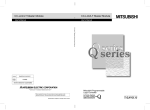
This manual provides the specifications, part names, setting, etc. of the AJ65SBT-CLB
CC-Link - CC-Link/LT bridge module (hereafter referred to as the AJ65SBT-CLB) that
is designated to be used as a remote device station in a CC-Link system.
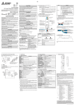
1.1 Overview
The AJ65SBT-CLB includes the bridge function to establish a connection between CCLink and CC-Link/LT.
Using the AJ65SBT-CLB connects the remote I/O of CC-Link/LT to a CC-Link system.
Any of the A series, QnA series and Q series can be used to configure a system,
realizing a compact wire-saving system.
AJ65SBT-CLB
Remote I/O station
Terminating resistor
Remote I/O station
CC-Link side
Power supply adapter
CC-Link/LT side
General power supply
24 V DC
Terminating resistor
Partner company's
product
Remote station
CL1Y4- T1B2
Remote station
CL2AD4-B
Y0
1-1
1-1
1
1 OVERVIEW
MELSEC-A
1.2 Features
1
The AJ65SBT-CLB has the following features.
(1) Seamless connection of two networks
The AJ65SBT-CLB is a bridge module that can connect CC-Link and CC-Link/LT
seamlessly.
Using RX and RY (bit devices), one bridge module can control up to 224 points
(448 points when both inputs and outputs are used).
(2) Confirmation of communication status of CC-Link/LT remote
stations
The data link statuses and I/O errors of CC-Link/LT remote stations can be
confirmed from the programmable controller CPU of the CC-Link master station.
(3) Configuration of CC-Link/LT using A, QnA series
A CC-Link/LT system can be configured using the MELSEC-A, QnA series via
CC-Link.
(4) Wire saving and easy installation
The one-touch connectors ensure easy installation by using as the CC-Link side
communication connectors.
(5) Compact size
The AJ65SBT-CLB has the same size as the AJ65SBTB1-8 compact remote
I/O module.
(Width 87.0 (3.43) height 49.0 (1.93) depth 40.0 (1.57) mm (inch))
Either of screws or DIN rail can be used to mount the module to a control panel.
1-2
1-2
2 SYSTEM CONFIGURATION
MELSEC-A
2 SYSTEM CONFIGURATION
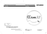
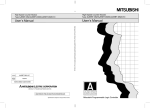
2.1 Overall Configuration
This section explains a system including the AJ65SBT-CLB.
For the transmission specifications, station-to-station distance, overall cable distance
(maximum transmission distance), etc. of CC-Link, refer to the user's manual of the
master module.
Refer to Section 3.3 for the wiring specifications.
Master
station
Remote I/O station
Intelligent
device station
AJ65SBT-CLB
CC-Link side
CC-Link/LT side
Remote station
Remote station
Remote station
CL2Y8-TP1B2
CL1PA
D1
CL2Y8-TP1B2
Y0
Y0
Power
supply
adapter
General
power
supply
Table 2.1 Network Wiring Specifications
Item
Transmission speed
Station-to-station distance
Max. no. of modules per drop line
Length of trunk line
T-branch interval
Max. length of drop line
Overall length of drop lines
T-branch
connection
Specifications
2.5 Mbps
625 kbps
156kbps
Not limited
8 modules
Remarks
35 m
100 m
500 m
Cable length between terminating resistors.
Length of drop lines not included
4m
15 m
Not limited
16 m
50 m
60 m
200 m
Max. cable length for one branch line
Total length of all drop lines
Length of trunk line (Drop line not included)
Master station
Interval length of T-branch
Length
of
*3
drop
Terminating line
resistor
Power
supply
adapter
*1
Length of drop line
Remote
station
Remote
station
Remote
station
*2
Remote
station
*3
Remote Terminating
station resistor
Remote
station
Remote
station
Distance
between stations
Remote
station
Remote
station
Trunk line
Drop line
Remote
station
1: The length of the drop line includes the length of 2. (The max. length of drop line and overall
length of drop lines include the length of 2.)
3: Refer to Section 4.5.4 for the terminating resistor mounting method.
2-1
2-1
2
2 SYSTEM CONFIGURATION
MELSEC-A
POINT
(1) The connection order of remote stations is not relevant to the station numbers.
(2) The remote station numbers are not necessarily consecutive. (Empty station
number does not cause data link failure.)
2
2.2 Applicable System
This section explains the applicable master modules and the precautions for system
configuration.
(1) The following table indicates the applicable master modules.
Model Name
Q series
QJ61BT11N, QJ61BT11
QnA series
AJ61QBT11, A1SJ61QBT11
A series
AJ61BT11, A1SJ61BT11
FX series
FX2N-16CCL-M
PCI board
Q80BD-J61BT11N, A80BD-J61BT11
Others
CC-Link partner maker's master module
The FX series can be used within the range of:
FX1N, FX1NC 128 points
FX2N, FX2NC 256 points
in the whole system.
2.2.1 Applicable software package
To carry out CC-Link / CC-link/LT diagnostics, GX Developer of Version 8.00A or later
is required.
2-2
2-2
2 SYSTEM CONFIGURATION
MELSEC-A
2.3 Precautions for System Configuration
(1) Arrangement of AJ65SBT-CLB
(a) CC-Link side
The AJ65SBT-CLB can be placed in any position as the remote device
station of the CC-Link system.
(b) CC-Link/LT side
Since T-branch connection can be made, the AJ65SBT-CLB can
apparently be placed midway through the trunk line. Note that the length of
the trunk line is defined as the length between two terminating resistors.
Remote
I/O station
Master
station
Remote
device station
Remote
I/O station
CC-Link side
AJ65SBT-CLB
CC-Link/LT side
Terminating resistor
*1
Length of drop line
Length of trunk line
Length
*3
of
Terminating drop
Power
line
resistor
supply
adapter
*1
Length of drop line
*3
*2
Remote
station
Remote
station
*2
*2
Remote
station
*2
Remote
station
Remote
station
Remote
station
Remote
station
Distance
between stations
Remote
station
Remote
station
Trunk line
Drop line
Remote
station
1 The length of drop line includes the length of 2. (The max. length of drop line and overall
length of drop lines include the length of 2.)
3 Refer to Section 4.5.4 for the terminating resistor mounting method.
(2) Number of CC-Link/LT side drop line branch stages
In the CC-Link/LT system, branch the drop line up to two stages.
The drop line cannot be branched to three or more stages.
Remote
station
Remote
station
Third drop line branch stage: cannot be wired.
Remote
station
2-3
Trunk line
Drop line
2-3
2 SYSTEM CONFIGURATION
MELSEC-A
(3) Mounting condition for CC-Link/LT dedicated power supply or
power supply adaptor
The mounting conditions for a dedicated power supply or power supply adapter
for the CC-Link/LT vary depending on the devices to be connected and the wiring
length.
Refer to the User’s Manual of the dedicated power supply or power supply
adapter for the conditions.
POINT
Always connect the dedicated power supply or power supply adapter to the trunk
line. (Connection to branch lines is not allowed.)
(4) Prevention of incorrect input/output from remote I/O module of CCLink/LT
To prevent incorrect input/output from remote I/O modules, design the system
while paying full attention to the following.
(a) When power is ON or OFF
Power ON the remote I/O module (Power on the dedicated power supply or
power supply adapter) before starting the data link.
Also, stop the data link before powering OFF the remote I/O module
(Powering off the dedicated power supply or power supply adapter).
Data link start
Master module
(Data link status)
Remote I/O module
(Power status)
2-4
Data link stop
Executed
Stopped
ON
OFF
2-4
2 SYSTEM CONFIGURATION
MELSEC-A
(b) Instantaneous power failure of remote I/O module
When instantaneous power failure occurs in the power source (24V DC) for
the remote I/O module, incorrect data may be input.
1) Causes of incorrect input due to instantaneous power failure
The hardware of the remote I/O module converts the supplied power of
24V DC into 5V DC inside the module and uses it for its own operation.
When instantaneous power failure occurs in the remote I/O module,
the following,
(Time until 5V DC is turned OFF inside the remote I/O module)
>(Response time from ON to OFF of the input ), is established.
Therefore, when the devices are refreshed within the time shown as
(1), data will be incorrectly input. (Especially, when the input response
time is set to the high-speed response type)
1)
Remote I/O module
(Power for module and
external power supply for input)
Remote I/O module
(Inside 5V DC)
Input (Xn)
Externally powering off for
input, turns input (Xn) OFF
after response time from ON to
OFF of Input unit.
2-5
Externally powering off for
input, turns input (Xn) ON
after response time from OFF
to ON of input module.
2-5
2 SYSTEM CONFIGURATION
MELSEC-A
2) Preventive measure against incorrect input
Install wiring so that the power is supplied from the same power
source to the power supply module, stabilized power supply and
external power supply for AC input.
Remote I/O module
AJ65SBT-CLB
DC input
Stabilized
power supply 24VDC
Power supply
adapter
Stabilized
power supply 24VDC
Remote I/O module
AJ65SBT-CLB
AC input
2-6
Stabilized
power supply 24VDC
External
supply
power
for input
Power supply
adapter
External
supply
power
for input
2-6
2 SYSTEM CONFIGURATION
MELSEC-A
2.4 Parts Sold Separately
The plugs for AJ65SBT-CLB are sold separately.
Please purchase them as necessary.
Mitsubishi model
name
Part model name
(manufacturer)
One-touch
connector plug for
communication
1, 2
A6CON-L5P
35505-6000BOM GF (3M)
communication line
0.5 (20 AWG)
shielded cable (drain wire)
0.5 (20 AWG)
Online connector for
communication 3
A6CON-LJ5P
35720-L200-B00
AK (3M)
⎯
One-touch connector
plug with terminating
resistor (one piece)
Color of
the cover
Specifications
A6CON-TR11
2.2 to 3.0
Red
⎯
⎯
⎯
⎯
⎯
With terminating resistor (110Ω)
⎯
A6CON-TR11N
With terminating resistor (110Ω) (built-in type)
1 Mitsubishi's A6CON-L5P includes 10 plugs.
2 Once insulation-displaced, the one-touch connector plugs cannot be reused.
3 Mitsubishi's A6CON-LJ5P includes 5 plugs.
REMARK
• As following table indicates, the optional plugs/connectors are compatible with the
connectors for this module.
Connector for this Module
One-touch connector for
communication
Optional Parts
• One-touch connector plug for communication
• Online connector for communication
• One-touch connector plug with terminating resistor
• Cables, connectors and terminating resistors on the CC-Link/LT side
For inquiries about the cables, connectors and/or terminating resistors on the CCLink/LT side, access the home page of the CC-Link Partner Association on the
Internet at http://www.cc-link.org/.
2-7
2-7
3 SPECIFICATIONS
MELSEC-A
3 SPECIFICATIONS
This chapter provides the specifications of the AJ65SBT-CLB.
3.1 General Specifications
Table 3.1 General specifications
Item
Specifications
Operating ambient
3
0 to 55°C
temperature
Storage ambient
-25 to 75°C
temperature
Operating ambient
humidity
5 to 95%RH, non-condensing
Storage ambient
humidity
Frequency
Vibration resistance
Compliant
Under
with JIS B
intermittent
3502 and
vibration
IEC 61131-2
Under
continuous
Operating
amplitude
———
3.5mm
2
8.4 to 150Hz
9.8m/s
———
5 to 8.4Hz
———
1.75mm
8.4 to 150Hz
4.9m/s
2
———
Sweep count
10 times each in
X, Y, Z directions
———
No corrosive gases
atmosphere
Operating altitude
0 to 2000m
3
Installation location
Overvoltage
Inside a control panel
II or less
1
Pollution degree
Half
vibration
2
Compliant with JIS B 3502 and IEC 61131-2 (147 m/s , 3 times each in 3 directions X, Y, Z)
Shock resistance
category
5 to 8.4Hz
Constant
acceleration
2
2 max.
1 : This indicates the section of the power supply to which the equipment is assumed to be connected
between the public electrical power distribution network and the machinery within premises.
Category II applies to equipment for which electrical power is supplied from fixed facilities.
The surge voltage withstand level for up to the rated voltage of 300V is 2500V.
2 : This index indicates the degree to which conductive material is generated in terms of the environment in
which the equipment is used.
Pollution level 2 is when only non-conductive pollution occurs. A temporary conductivity caused by
condensing must be expected occasionally.
3 : Do not use or store the programmable controller under pressure higher than the atmospheric pressure of
altitude 0m. Doing so may cause malfunction. When using the programmable controller under pressure,
please consult your local Mitsubishi representative.
3-1
3-1
3 SPECIFICATIONS
MELSEC-A
3.2 Performance Specifications
The following table provides the performance specifications of the AJ65SBT-CLB.
Table 3.2 Performance specifications
Item
Station type
CC-Link Version
CC-Link side
2 stations
Number of
occupied
stations
4 stations
8 stations
(4 occupied stations 2
modules)
AJ65SBT-CLB connection position
Communication specifications
CC-Link/LT side
Control
specifications
External connection system
Maximum number of link points
Number in parentheses assumes
use of the same I/O addresses
Number of link points per station
Number in parentheses assumes
use of the same I/O addresses
256 points each for RX and RY (32 points are used in the system)
32 points each for RWr and RWw
No restrictions
One-touch connector for communication [transmission circuit] (5-pin,
insulation displacement type connector plug is sold separately)
<Sold separately> Online connector for communication: A6CON-LJ5P
4-point mode
8-point mode
16-point mode
224 points (448 points)
4 points
(8 points)
8 points
(16 points)
16 points
(32 points)
Transmission speed
Communication system
2.5Mbps/625kbps/156kbps
BITR system (Broadcastpolling
Transmission path format
Error control system
T-branch system
CRC
Number of connected modules
Remote station number
56 modules
1 to 56
AJ65SBT-CLB connection position
Connected at the end of the trunk line
Network diagnostics, internal loopback diagnostics, slave station
separation, automatic return to system
RAS functions
Interval Timed Response)
2
Connection cable 1
Module mounting screw
Common
Specifications
Remote device station
Ver.1.10
64 points each for RX and RY (16 points are used in the system)
8 points each for RWr and RWw
128 points each for RX and RY (16 points are used in the system)
16 points each for RWr and RWw
Module mounting direction
24V DC power
supply 2
Level of protection
Weight
Voltage
Current consumption
Start-time current
Dedicated flat cable (0.75mm 4) 4, VCTF cable 3, high flexible
cable 4
M4 0.7mm 16mm or more screw
Tightening torque range 0.78 to 1.08Nxm
DIN rail can also be used for mounting.
Can be mounted in any of six orientations.
(No restrictions on mounting directions)
24V DC externally supplied (20.4V DC to 26.4V DC, ripples within 5%)
0.075A (When 24V DC)
0.165A (When 24V DC)
IP2X
0.09kg
1 Performance of the CC-Link/LT cannot be guaranteed for use of cables other than the dedicated flat cables, VCTF
cables and high flexible cables.
2 Supplied by the dedicated power supply or power supply adaptor of CC-Link/LT.
3 For VCTF cable specifications, see Table 3.3.
4 Use the dedicated flat cables and high flexible cables accredited by the CC-Link Partner Association. (Refer to Section
2.4.)
3-2
3-2
3
3 SPECIFICATIONS
MELSEC-A
Table 3.3 VCTF cable specifications (Extract from JIS C 3306)
Conductor
No. of cores Nominal crossComposition
Outside
sectional area No. of wires/wire diameter diameter
Type
Vinyl cabtyre,
4
Round cord
2
0.75mm
30/0.18mm
Insulator
Sheath
thickness
thickness
0.6mm
1.0mm
1.1mm
Conductor
resistance
(20
)
25.1
Ω/km
3.3 Network Wiring Specifications
3.3.1 CC-Link network wiring specifications
For the network wiring specifications of CC-Link, refer to the user's manual of the
master module.
3.3.2 CC-Link/LT network wiring specifications
The following indicates the network wiring specifications of CC-Link/LT.
Item
Specifications
Transmission speed
2.5 Mbps
Distance between stations
625 kbps
Not limited
Max. no. of connectable
8 modules
modules per drop line
Length of trunk line
35 m
T-branch interval
Master
station
Remarks
156 kbps
100 m
500 m
Not limited
Max. cable length per branch
Max. length of drop line
4m
16 m
60 m
Overall length of drop lines
15 m
50 m
200 m
Remote
I/O station
Cable length between
terminating resistors. Length
of drop lines not included
Remote
device station
line
Total length of all drop lines
Remote
I/O station
Length of trunk line (Drop line not included)
CC-Link side
AJ65SBT-CLB
CC-Link/LT side
T-branch
Length
of
connection
drop
*3 line Power
Terminating
supply
resistor
adapter
Length
of
drop
line
Interval length of T-branch
Remote
station
*1 *2
Remote
station
Remote
station
Remote
station
Remote
station
Terminating
resistor
*3
Remote
station
Remote
station
Distance
between stations
Remote
station
Remote
station
Trunk line
Drop line
Remote
station
1 The length of drop line includes the length of 2. (The max. length of drop line and overall
length of drop lines include the length of 2.)
3 Refer to Section 4.5.4 for the terminating resistor mounting method.
3-3
3-3
3 SPECIFICATIONS
MELSEC-A
POINT
When connecting multiple lines with dedicated connectors to form one trunk line,
the number of connections must be 10 or less.
Line
connection
Master station
Terminating
resistor
Remote
station
Power
supply
adapter
Remote
station
Remote
station
3-4
Remote
station
Terminating
resistor
Remote
station
Remote
station
3-4
3 SPECIFICATIONS
MELSEC-A
3.4 Concept of Remote Input/Output
This section explains the I/O signals for the AJ65SBT-CLB module.
Example: The following provides an example of setting the AJ65SBT-CLB to 2
occupied stations and 4-point mode.
Master
station
Station 1
1 station
occupied
CC-Link side
Station 2
2 stations
occupied
Station 3
1 station
occupied
AJ65SBT-CLB
CC-Link/LT side
Station 1
Station 2
4 input
8 input
points
points
CL1X4-D1B2 CL2X8-D1B2
Station 3
4 output
points
CL1Y4-T1B2
Station 4
2 output
points
Station 5
16 input
points
CL2X16-D1M1V
CL1Y2-T1D2S
CC-Link master station
Remote input
Station 1
Station 2
Station 3
RX0F to RX00
RX1F to RX10
RX2F to RX20
RX3F to RX30
RX4F to RX40
RX5F to RX50
RX6F to RX60
RX7F to RX70
to
1 station
2 station
CC-Link/LT side
AJ65SBT-CLB
RX2F to RX20
RX3F to RX30
RX4F to RX40
RX5F to RX50
1 station
48 points
1) 4 points
1 station
2) 8 points
2 stations
System area, 3) 4 points
16 points
4) 2 points
Empty,2 points
1 station
1 station
RX7FF to RX7F0
5) 16 points
4 stations
Section 3.5.1 to Section 3.5.3
Section 3.5.4
3-5
3-5
3 SPECIFICATIONS
MELSEC-A
3.5 Remote I/O Signals for CC-Link Master Module
This section explains the I/O signals of the AJ65SBT-CLB for the CC-Link master
module.
3.5.1 Remote I/O signal list when 2 stations are occupied
Out of 64 points, 16 points are used as a system area.
Signal Direction: AJ65SBT-CLB
Remote input (RX)
master module
Name
Remote output (RY)
AJ65SBT-CLB
Name
RYn0
RXn0
to
Signal Direction: Master module
Used by CC-Link/LT remote
RX(n 2)F
to
Used by CC-Link/LT remote
RY(n 2)F
RX(n+3)0
to
Use prohibited
RX(n 3)9
RX(n 3)A
Error status flag
RY(n 3)0
RX(n 3)B
Remote READY
to
RY(n 3)F
RX(n 3)C
RX(n 3)D
RX(n 3)E
Use prohibited
Use prohibited
RX(n 3)F
POINT
The prohibited devices are used by the system and therefore cannot be used by
the user.
If data is written to the buffer memory area corresponding to the prohibited device
or to the device specified for auto refresh, the functions of the AJ65SBT-CLB
cannot be guaranteed.
3-6
3-6
3 SPECIFICATIONS
MELSEC-A
3.5.2 Remote I/O signal list when 4 stations are occupied
Out of 128 points, 16 points are used as a system area.
Signal Direction: AJ65SBT-CLB
Remote input (RX)
Master module
Name
Remote output (RY)
AJ65SBT-CLB
Name
RYn0
RXn0
to
Signal Direction: Master module
Used by CC-Link/LT remote
RX(n 6)F
to
Used by CC-Link/LT remote
RY(n 6)F
RX(n 7)0
to
Use prohibited
RX(n 7)9
RX(n 7)A
Error status flag
RX(n 7)B
Remote READY
RX(n 7)E
to
Use prohibited
RY(n 7)F
RX(n 7)C
RX(n 7)D
RY(n 7)0
Use prohibited
RX(n 7)F
POINT
The prohibited devices are used by the system and therefore cannot be used by
the user.
If data is written to the buffer memory area corresponding to the prohibited device
or to the device specified for auto refresh, the functions of the AJ65SBT-CLB
cannot be guaranteed.
3-7
3-7
3 SPECIFICATIONS
MELSEC-A
3.5.3 Remote I/O signal list when 8 stations are occupied (4 occupied stations
2 modules)
Out of 256 points, 32 points are used as a system area.
When 8 stations (4 occupied stations 2 modules) are occupied, two 4-station
occupying modules are placed in series.
Signal Direction: AJ65SBT-CLB
Remote input (RX)
Master module
Name
Remote output (RY)
AJ65SBT-CLB
Name
RYn0
RXn0
to
Signal Direction: Master module
Used by CC-Link/LT remote
RX(n 6)F
to
Used by CC-Link/LT remote
RY(n 6)F
RX(n 7)0
to
Use prohibited
RX(n 7)9
RX(n 7)A
Error status flag
RX(n 7)B
Remote READY
RX(n 7)E
to
Use prohibited
RY(n 7)F
RX(n 7)C
RX(n 7)D
RY(n 7)0
Use prohibited
RX(n 7)F
RX(n 8)0
to
RY(n 8)0
Used by CC-Link/LT remote
RX(n E)F
to
Used by CC-Link/LT remote
RY(n E)F
RX(n F)0
to
Use prohibited
RX(n F)9
RX(n F)A
Error status flag
RY(n F)0
RX(n F)B
Remote READY
to
RY(n F)F
RX(n F)C
RX(n F)D
RX(n F)E
Use prohibited
Use prohibited
RX(n F)F
POINT
• The prohibited devices are used by the system and therefore cannot be used by
the user.
If data is written to the buffer memory area corresponding to the prohibited device
or to the device specified for auto refresh, the functions of the AJ65SBT-CLB
cannot be guaranteed.
• Set the station data as two modules that occupy four remote device stations.
• The same data is stored into "RXn 7A, RXn 7B" and "RXn FA, RXn FB".
3-8
3-8
3 SPECIFICATIONS
MELSEC-A
3.5.4 Details of remote I/O signals
This section explains the assignment and functions of the CC/Link remote
inputs/outputs.
(1) Remote I/O signal list for 4-point mode setting
(a) The following table lists the I/O signals for 2 occupied station setting
Remote input (RX) of
CC-Link
Remote input (X) of CC-Link/LT
F
RXnF to RXn0
E
D
C
Station number 4
B
A
9
8
7
Station number 3
6
5
4
3
2
1
0
Station number 2
Station number 1
Station number 12 Station number 11 Station number 10
Station number 9
to
to
RX(n 2)F to RX(n 2)0
RX(n 3)F to RX(n 3)0
Use prohibited
Remote output (RY) of
CC-Link
Remote output (Y) of CC-Link/LT
F
RYnF to RYn0
E
D
C
Station number 4
B
A
9
8
7
Station number 3
6
5
4
3
2
1
0
Station number 2
Station number 1
Station number 12 Station number 11 Station number 10
Station number 9
to
to
RY(n 2)F to RY(n 2)0
RY(n 3)F to RY(n 3)0
Use prohibited
(b) The following table lists the I/O signals for 4 occupied station setting
Remote input (RX) of
CC-Link
RXnF to RXn0
F
E
D
C
Station number 4
B
A
9
8
7
Station number 3
6
5
4
Station number 2
3
2
1
0
Station number 1
to
to
RX(n 6)F to RX(n 6)0
Station number 28 Station number 27 Station number 26 Station number 25
RX(n 7)F to RX(n 7)0
Use prohibited
Remote output (RY) of
Remote output (Y) of CC-Link/LT
CC-Link
RYnF to RYn0
3-9
Remote input (X) of CC-Link/LT
F
E
D
C
Station number 4
B
A
9
8
7
Station number 3
6
5
4
Station number 2
3
2
1
0
Station number 1
to
to
RY(n 6)F to RY(n 6)0
Station number 28 Station number 27 Station number 26 Station number 25
RY(n 7)F to RY(n 7)0
Use prohibited
3-9
3 SPECIFICATIONS
MELSEC-A
(c) The following table lists the I/O signals for 8 occupied station (4 occupied
stations 2 modules) setting
Remote input (RX) of
CC-Link
RXnF to RXn0
F
E
D
C
Station number 4
B
A
9
8
7
Station number 3
6
5
4
Station number 2
3
2
1
0
Station number 1
to
to
RX(n 6)F to RX(n 6)0
Station number 28 Station number 27 Station number 26 Station number 25
RX(n 7)F to RX(n 7)0
Use prohibited
RX(n 8)F to RX(n 8)0
Station number 32 Station number 31 Station number 30 Station number 29
to
to
RX(n E)F to RX(n E)0
Station number 56 Station number 55 Station number 54 Station number 53
RX(n F)F to RX(n F)0
Use prohibited
Remote output (RY) of
Remote output (Y) of CC-Link/LT
CC-Link
RYnF to RYn0
3 - 10
Remote input (X) of CC-Link/LT
F
E
D
C
Station number 4
B
A
9
8
7
Station number 3
6
5
4
Station number 2
3
2
1
0
Station number 1
to
to
RY(n 6)F to RY(n 6)0
Station number 28 Station number 27 Station number 26 Station number 25
RY(n 7)F to RY(n 7)0
Use prohibited
RY(n 8)F to RY(n 8)0
Station number 32 Station number 31 Station number 30 Station number 29
to
to
RY(n E)F to RY(n E)0
Station number 56 Station number 55 Station number 54 Station number 53
RY(n F)F to RY(n F)0
Use prohibited
3 - 10
3 SPECIFICATIONS
MELSEC-A
(2) Remote I/O signal list for 8-point mode setting
(a) The following table lists the I/O signals for 2 occupied station setting
Remote input (RX) of
CC-Link
Remote input (X) of CC-Link/LT
F
E
RXnF to RXn0
D
C
B
A
9
8
7
6
Station number 2
5
4
3
2
1
0
1
0
1
0
1
0
Station number 1
to
to
RX(n 2)F to RX(n 2)0
Station number 6
Station number 5
RX(n 3)F to RX(n 3)0
Use prohibited
Remote output (RY) of
Remote output (Y) of CC-Link/LT
CC-Link
F
E
RYnF to RYn0
D
C
B
A
9
8
7
6
Station number 2
5
4
3
2
Station number 1
to
to
RY(n 2)F to RY(n 2)0
Station number 6
RY(n 3)F to RY(n 3)0
Station number 5
Use prohibited
(b) The following table lists the I/O signals for 4 occupied station setting
Remote input (RX) of
CC-Link
Remote input (X) of CC-Link/LT
F
E
RXnF to RXn0
D
C
B
A
9
8
6
Station number 2
5
Remote output (RY) of
Remote output (Y) of CC-Link/LT
F
E
D
C
B
A
RY(n 7)F to RY(n 7)0
9
8
7
6
Station number 2
to
RY(n 6)F to RY(n 6)0
2
Station number 13
Use prohibited
RYnF to RYn0
3
to
Station number 14
RX(n 7)F to RX(n 7)0
CC-Link
4
Station number 1
to
RX(n 6)F to RX(n 6)0
3 - 11
7
5
4
3
2
Station number 1
to
Station number 14
Station number 13
Use prohibited
3 - 11
3 SPECIFICATIONS
MELSEC-A
(c) The following table lists the I/O signals for 8 occupied station (4 occupied
stations 2 modules) setting
Remote input (RX) of
CC-Link
Remote input (X) of CC-Link/LT
F
E
RXnF to RXn0
D
C
B
A
9
8
6
Station number 2
5
Station number 16
Station number 28
0
Station number 27
Use prohibited
Remote output (RY) of
Remote output (Y) of CC-Link/LT
F
E
D
C
B
A
9
8
7
6
Station number 2
to
5
4
3
2
Station number 1
to
Station number 14
RY(n 7)F to RY(n 7)0
Station number 13
Use prohibited
Station number 16
to
RY(n F)F to RY(n F)0
1
Station number 15
RX(n F)F to RX(n F)0
RY(n E)F to RY(n E)0
0
to
RX(n E)F to RX(n E)0
RY(n 8)F to RY(n 8)0
1
Station number 13
to
RY(n 6)F to RY(n 6)0
2
Use prohibited
RX(n 8)F to RX(n 8)0
RYnF to RYn0
3
to
Station number 14
RX(n 7)F to RX(n 7)0
CC-Link
4
Station number 1
to
RX(n 6)F to RX(n 6)0
3 - 12
7
Station number 15
to
Station number 28
Station number 27
Use prohibited
3 - 12
3 SPECIFICATIONS
MELSEC-A
(3) Remote I/O signal list for 16-point mode setting
(a) The following table lists the I/O signals for 2 occupied station setting
Remote input (RX) of
CC-Link
Remote input (X) of CC-Link/LT
F
E
D
C
B
A
9
8
7
6
5
RXnF to RXn0
Station number 1
to
to
RX(n 2)F to RX(n 2)0
Station number 3
RX(n 3)F to RX(n 3)0
Use prohibited
Remote output (RY) of
Remote output (Y) of CC-Link/LT
CC-Link
F
E
D
C
B
A
9
8
7
6
RYnF to RYn0
Station number 1
to
to
RY(n 2)F to RY(n 2)0
Station number 3
RY(n 3)F to RY(n 3)0
Use prohibited
5
4
3
2
1
0
4
3
2
1
0
(b) The following table lists the I/O signals for 4 occupied station setting
Remote input (RX) of
CC-Link
Remote input (X) of CC-Link/LT
F
E
D
C
B
A
RXnF to RXn0
8
7
6
5
4
3
2
1
0
4
3
2
1
0
Station number 1
to
to
RX(n 6)F to RX(n 6)0
Station number 7
RX(n 7)F to RX(n 7)0
Use prohibited
Remote output (RY) of
Remote output (Y) of CC-Link/LT
CC-Link
3 - 13
9
F
E
D
C
B
A
9
8
7
6
RYnF to RYn0
Station number 1
to
to
RY(n 6)F to RY(n 6)0
Station number 7
RY(n 7)F to RY(n 7)0
Use prohibited
5
3 - 13
3 SPECIFICATIONS
MELSEC-A
(c) The following table lists the I/O signals for 8 occupied station (4 occupied
stations 2 modules) setting
Remote input (RX) of
CC-Link
Remote input (X) of CC-Link/LT
F
E
D
C
B
A
9
RXnF to RXn0
8
7
6
5
3
2
1
0
4
3
2
1
0
Station number 1
to
to
RX(n+6)F to RX(n+6)0
Station number 7
RX(n+7)F to RX(n+7)0
Use prohibited
RX(n+8)F to RX(n+8)0
Station number 8
to
to
RX(n+E)F to RX(n+E)0
Station number 14
RX(n+F)F to RX(n+F)0
Use prohibited
Remote input (RY) of
Remote input (Y) of CC-Link/LT
CC-Link
4
F
E
D
C
B
A
9
8
7
6
RYnF to RYn0
Station number 1
to
to
RY(n+6)F to RY(n+6)0
Station number 7
RY(n+7)F to RY(n+7)0
Use prohibited
RY(n+8)F to RY(n+8)0
Station number 8
to
to
RY(n+E)F to RY(n+E)0
Station number 14
RY(n+F)F to RY(n+F)0
Use prohibited
5
(4) Functions of remote I/O signals
Device No.
Signal Name
Description
Turns on when a remote I/O error occurs on CC-Link/LT side or when all
RX(n 3)A
1
Error status flag
stations or remote stations become faulty. Automatically turns off upon
recovery from the error.
Turns on during normal operation.
RX(n 3)B
2
Remote READY
Turns off in the CC-Link/LT side self-loopback test mode or when a switch
error occurs on a CC-Link/LT side.
1: When 4 stations are occupied
When 8 stations are occupied
2: When 4 stations are occupied
When 8 stations are occupied
3 - 14
RX(n 7)A
RX(n 7)A, RX(n F)A
RX(n 7)B
RX(n 7)B, RX(n F)B
3 - 14
3 SPECIFICATIONS
MELSEC-A
3.6 Concept of the Number of Control Points (Point Mode Setting for CC-Link/LT and
Number of Occupied Stations Setting for CC-Link)
This section explains the concept of the settings required for system configuration, i.e.,
point mode setting and number of occupied stations setting.
The point mode setting sets the number of points that can be controlled for each
occupied remote station in the CC-Link/LT.
The point mode has three different modes: 4-point mode, 8-point mode, and 16-point
mode. If the number of occupied stations is the same, the number of remote stations that
can be controlled in the CC-Link/LT changes depending on the setting of the point mode.
Note that, when connecting a remote device station to the CC-Link/LT system, set the
16-point mode in the point mode setting for the CC-Link/LT.
3.6.1 Setting number of occupied stations
This section explains a simple setting method of the point mode setting and number of
occupied stations setting.
As the point mode, use the 4-point mode. According to the number of I/O points of the
remote station, refer to the following table and set the number of occupied stations.
Number of Remote
Station I/O Points
48 points or less
49 to 112 points
Number of Occupied Stations Setting
of AJ65SBT-CLB
2 stations
4 stations
8 stations
(4 occupied stations 2 modules)
113 to 224 points
Point Mode Setting of
AJ65SBT-CLB
4-point mode
POINT
Since the default setting is the 8-point mode, change it to the 4-point mode.
3.6.2 Setting point mode
This section explains the point mode setting and the application method for number of
occupied stations setting.
(1)
If the number of occupied stations is set the same, the number of controllable remote
stations changes depending on the point mode setting, as the following table shows.
Number of Occupied
Stations Setting
Point mode
setting
4-point mode
8-point mode
16-point mode
(2)
3 - 15
2 Occupied
Stations
4 Occupied
Stations
12 stations
6 stations
3 stations
28 stations
14 stations
7 stations
8 Occupied Stations
(4 occupied stations
2 modules)
56 stations
28 stations
14 stations
If the remote module is the same, the number of occupied stations changes due
to the point mode.
For example, if a 16-point module is used, the occupied station number changes
from 4 occupied stations to 2 occupied stations to 1 occupied station when the point
mode changes from the 4-point mode to the 8-point mode to the 16-point mode.
3 - 15
3 SPECIFICATIONS
(3)
Master
station
CC-Link side
MELSEC-A
As the point mode, it is recommended to use the 4-point mode that has the least
number of empty points.
Example: In the case of one 2-point remote station, five 4-point remote stations,
one 8-point remote station and one 16-point remote station
Station 1
2 stations
occupied
Station 2
1 station
occupied
Station 3
1 station
occupied
AJ65SBT-CLB
CC-Link/LT side
Station 1
4 input
points
Station 2
8 input
points
CL1X4-D1B2 CL2X8-D1B2
4-point mode
(4 points/station)
Number of occupied
stations: 2 stations
(maximum 48 points)
Total number of
stations: 12 stations
1) 4 points
X/Y0
X/Y10
1 station
2) 8 points
2 station
3) 4 points
4) 2 points
1 station
Empty, 2 points
1) 4 points
Empty, 4 points
2) 8 points
X/Y10
1 station
3) 4 points
Empty, 4 points
5) 16 points
4) 2 points
4 station
Empty, 6 points
6) 4 points
7) 4 points
8) 4 points
Use
prohibited
16 points
1 station
1 station
X/Y30
6) 4 points
Empty, 4 points
7) 4 points
Empty, 4 points
8) 4 points
Empty, 4 points
CL1Y2-T1D2S
CL1XY8-DT1B2
CL1Y4-T1B2
1 station
16-point mode
(16 points/station)
Number of occupied
stations: 4 stations
(maximum 112 points)
Total number of
stations: 8 stations
X/Y0
16-point mode (4 points/station)
Number of occupied stations: 8 stations
(4 occupied stations 2 stations)
(maximum 224 points)
Total number of stations: 8 stations
X/Y0
1) 4 points
Empty,12points
1 station
1 station
1) 4 points
Empty,12points
1 station
2) 8 points
1 station
Empty, 8 points
X/Y30
1 station
1 station
X/Y20
1 station
3) 4 points
Empty,12points
X/Y30
4) 2 points
Empty,14points
1 station
1 station
Empty,12points
Empty, 8 points
3) 4 points
Empty,12points
1 station
1) 4 points
2) 8 points
1 station
2 station
X/Y80
X/Y90
X/Y10
X/Y10
1 station
1 station
4) 2 points
Empty,14points
1 station
Empty,96points
X/Y40
X/Y40
1 station
5) 16 points
X/Y50
X/Y50
6) 4 points
Empty,12points
X/Y60
1 station
X/Y70
1 station
1 station
7) 4 points
Empty,12points
1 station
X/Y70
8) 4 points
Empty,12points
6) 4 points
Empty,12points
X/Y60
7) 4 points
Empty,12points
5) 16 points 1 station
1 station
Empty,48points
Use
prohibited
16 points
CL1Y4-T1B2
Station 8
4 output
points
X/Y20
5) 16 points
1 station
CL2X16-D1M1V
Station 6
4 input/output
points
X/Y20
X/Y20
X/Y23
CL1Y4-T1B2
Station 7
4 output
points
Station 4
2 output
points
8-point mode
(8 points/station)
Number of occupied
stations: 4 stations
(maximum 112 points)
Total number of
stations: 9 stations
X/Y0
Station 5
16 input
points
Station 3
4 output
points
1station
Use
prohibited
16 points
Use
prohibited
16 points
First module
Second module
When 4 occupied stations and 16-point mode are selected in
the above system, Station 8 cannot be set. (When the 16-point
mode has been set for 4 occupied stations, only up to 7 stations can be set.)
Set 8 occupied stations (4 occupied stations 2 modules) as shown above,
or change the point mode setting to the 4-point mode or 8-point mode.
3 - 16
3 - 16
3 SPECIFICATIONS
(4)
Station
No.
Model Name
MELSEC-A
The assignment of the I/O numbers is explained below using the assignment
sheet in the Appendices. It is an example where the number of occupied stations
is 2 and the point mode setting is the 4-point mode as shown in the configuration
of the Section (3).
Input
Output
Station
No.
Model Name
Input
Output
(2 stations occupied)
(4 stations occupied)
3 - 17
3 - 17
3 SPECIFICATIONS
MELSEC-A
3.7 Remote Registers
The AJ65SBT-CLB has the remote registers to make data communication with the
master module.
This section explains the assignment and data structure of the remote registers of the
AJ65SBT-CLB.
3.7.1 Assignment of remote registers
The following tables indicate the assignment of the remote registers.
(1) RWw
Address
Remote Register Definition
Initial value
Reference
RWwn
Last station number setting
0
Sec. 3.7.2
RWwn 1
Data link stop/restart instructions
0
Sec. 3.7.3
RWwn 2
RWwn 3
to
RWwn F
Error status flag clear
0
Sec. 3.7.4
Use prohibited
n: Address assigned to the master station in station number setting.
(2) RWr
(a) When 2 stations are occupied
Address
Remote Register Definition
Reference
RWrn
Data of operating statuses
Sec. 3.7.5
RWrn 1
Data of faulty station : Station number 1 to 12
Sec. 3.7.6
RWrn 2
Remote I/O error data :Station number 1 to 12
Sec. 3.7.7
RWrn 3
Data of remote station connection
Sec. 3.7.8
RWrn 4
RWrn 5
to
RWrn 7
Setting data
Sec. 3.7.9
Use prohibited
n: Address assigned to the master station in station number setting.
(b) When 4 stations are occupied
Address
Remote Register Definition
Reference
RWrn
Data of operating states
Sec. 3.7.5
Data of faulty station : Station number 1 to 28
Sec. 3.7.6
Remote I/O error data :Station number 1 to 28
Sec. 3.7.7
Data of remote station connection
Sec. 3.7.8
Setting data
Sec. 3.7.9
RWrn 1
RWrn 2
RWrn 3
RWrn 4
RWrn 5
RWrn 6
RWrn 7
RWrn 8
to
RWrn F
Use prohibited
n: Address assigned to the master station in station number setting.
3 - 18
3 - 18
3 SPECIFICATIONS
MELSEC-A
(c) When 8 stations (4 occupied stations
occupied
2 modules) are
First module
Address
Remote Register Definition
Reference
RWrn
Data of operating statuses
Sec. 3.7.5
Data of faulty station : Station number 1 to 32
Sec. 3.7.6
Remote I/O error data : Station number 1 to 32
Sec. 3.7.7
Data of remote station connection
Sec. 3.7.8
Setting data
Sec. 3.7.9
RWrn 1
RWrn 2
RWrn 3
RWrn 4
RWrn 5
RWrn 6
RWrn 7
RWrn 8
Use prohibited
to
RWrn F
Second module
Address
Remote Register Definition
Reference
RWr(n 1)
Data of operating states
Sec. 3.7.5
Data of faulty station : Station number 33 to 56
Sec. 3.7.6
Remote I/O error data : Station number 33 to 56
Sec. 3.7.7
Data of remote station connection
Sec. 3.7.8
Setting data
Sec. 3.7.9
RWr(n 1) 1
RWr(n 1) 2
RWr(n 1) 3
RWr(n 1) 4
RWr(n 1) 5
RWr(n 1) 6
RWr(n 1) 7
RWr(n 1) 8
to
Use prohibited
RWr(n 1) F
n: Address assigned to the master station in station number setting.
POINT
The prohibited remote register areas are used by the system and therefore cannot
be used by the user.
If data is written to the buffer memory area corresponding to the prohibited remote
register area or to the device specified for auto refresh, the functions of the
AJ65SBT-CLB cannot be guaranteed.
3 - 19
3 - 19
3 SPECIFICATIONS
MELSEC-A
3.7.2 Last station number setting (common to 2, 4 and 8 occupied stations (4 occupied
stations 2 modules): Address RWwn)
The setting status of the last station number is stored.
Bit
Name
b0 to b7
Empty
Description
Initial value
Fixed at 0
Set the last station number for a data link.
This eliminates the processing of data link
to the non-connected stations, reducing the
link refresh time.
If the value is set beyond the number of
connectable stations (refer to Section
b8 to b13
Last station number
setting
3.6.2), the setting will be ignored.
<Setting range>
0
2 occupied stations: Station 1 to 12
4 occupied stations: Station 1 to 28
8 occupied stations (4 occupied stations
2 modules): Station 1 to 56
If the value of 0 or more than 56 is set, a
data link is performed with the number of
stations within the setting range.
b14, b15
Empty
Fixed at 0
3.7.3 Data link stop/restart instructions (common to 2, 4 and 8 occupied stations (4 occupied
stations 2 modules): Address RWwn+1)
Data link stop and restart are controlled. When a data link stop and a data link restart
are requested simultaneously, the data link stop has higher priority.
Bit
Name
b0
Data link stop
b1 to b14
Empty
b15
Data link restart
Description
0 : Data link stop not requested
1 : Data link stop requested
Initial value
0
Fixed at 0
0 : Data link restart not requested
1 : Data link restart requested
0
3.7.4 Error status flag clear (common to 2, 4 and 8 occupied stations (4 occupied stations
2 modules): Address RWwn+2)
Error of station outside control range is cleared.
Bit
b0 to b2
Name
Empty
Error of station
b3
outside control range
clear
b4 to b15
3 - 20
Empty
Description
Initial value
Fixed at 0
0 : Clear not requested
1 : Clear requested
0
Fixed at 0
3 - 20
3 SPECIFICATIONS
MELSEC-A
3.7.5 Data of operating statuses (common to 2, 4 and 8 occupied stations (4 occupied
stations 2 modules): Address RWrn)
The CC-Link/LT side operating status is stored.
Bit
Name
b0
Data link status
b1
Initial communication status
b2 to b7
Empty
b8
Data link failure
b9
All stations failed
b10
Remote I/O error
b11
Error of station outside control range
Description
0: Data link stopped
1: Data link being executed
0: Initial communication not completed
1: Initial communication completed
Fixed at 0
0: Data link normal
1: One or more faulty station in data link identified
0: One or more normal data link station identified
1: All stations are faulty
0: No remote I/O error
1: One or more faulty remote I/O station
0: No error
1: Remote station(s) set to the station number higher than the last
of refresh range
b12
Point mode setting error
b13
Transmission speed setting error
b14
Switching during operation
b15
Hardware failure
3 - 21
0: Normal
1: Point mode switch set outside valid range
0: Normal
1: Transmission rate setting switch set outside valid range
0: No switching
1: Switching identified
0: Normal
1: Failure identified by self-loopback test
3 - 21
3 SPECIFICATIONS
MELSEC-A
3.7.6 Data of faulty station (2 occupied stations: Address RWrn 1, common to 4 and 8
occupied stations (4 occupied stations 2 modules): Address RWrn 1, RWrn 2)
The data link statuses of the CC-Link/LT remote stations are stored.
• When 2 stations are occupied, the data of faulty stations in the CC-Link/LT is stored
into RWrn+1.
• When 4 or 8 stations (4 occupied stations 2 modules) are occupied, the data of
faulty stations in the CC-Link/LT is stored into RWrn 1, RWrn 2.
Number of Occupied Stations
Number of Stations
When 2 stations are occupied
1 to 12 stations
When 4 stations are occupied
1 to 28 stations
When 8 stations (4
First module
1 to 32 stations
Second module
33 to 56 stations
occupied stations
2
modules) are occupied
(1) When 2 stations are occupied
Address
b15
b14
b13
b12
b11
b10
b9
b8
b7
b6
b5
b4
b3
b2
b1
b0
Station Station Station Station Station Station Station Station Station Station Station Station
12
11
10
9
8
7
6
5
4
3
2
1
RWrn 1
0: Normal
1: Data link error
(2) When 4 stations are occupied
Address
b15
b14
b13
b12
b11
b10
b9
b8
b7
b6
b5
b4
b3
b2
b1
b0
RWrn 1
Station Station Station Station Station Station Station Station Station Station Station Station Station Station Station Station
16
15
14
13
12
11
10
9
8
7
6
5
4
3
2
1
RWrn 2
Station Station Station Station Station Station Station Station Station Station Station Station
28
27
26
25
24
23
22
21
20
19
18
17
0: Normal
1: Data link error
(3) When 8 stations (4 occupied stations 2 modules) are occupied
(first module: 1 to 32 stations, second module: 33 to 56 stations)
Address
b15
b14
b13
b12
b11
b10
b9
b8
b7
b6
b5
b4
b3
b2
b1
b0
Station Station Station Station Station Station Station Station Station Station Station Station Station Station Station Station
RWrn 1
16
15
14
13
12
11
10
9
8
7
6
5
4
3
2
1
RWrn 2
Station Station Station Station Station Station Station Station Station Station Station Station Station Station Station Station
32
31
30
29
28
27
26
25
24
23
22
21
20
19
18
17
RWr(n 1) 1
Station Station Station Station Station Station Station Station Station Station Station Station Station Station Station Station
48
47
46
45
44
43
42
41
40
39
38
37
36
35
34
33
RWr(n 2) 2
Station Station Station Station Station Station Station Station
56
55
54
53
52
51
50
49
0: Normal
1: Data link error
3 - 22
3 - 22
3 SPECIFICATIONS
MELSEC-A
3.7.7 Remote I/O error data (2 occupied stations: Address RWrn 2, common to 4 and 8
occupied stations (4 occupied stations 2 modules): Address RWrn 3, RWrn 4)
The remote I/O error occurrence statuses of the CC-Link/LT remote stations during
data link are stored.
For the error definition, refer to the manual of the corresponding CC-Link/LT remote
station.
• When 2 stations are occupied, the remote I/O errors of CC-Link/LT are stored into
RWrn 2.
• When 4 or 8 stations (4 occupied stations 2 modules) are occupied, the remote
I/O errors of CC-Link/LT are stored into RWrn 3, RWrn 4.
(1) When 2 stations are occupied
Address
b15
b14
b13
b12
b11
b10
b9
b8
b7
b6
b5
b4
b3
b2
b1
b0
Station Station Station Station Station Station Station Station Station Station Station Station
12
11
10
9
8
7
6
5
4
3
2
1
RWrn 2
0: No remote I/O error occurred
1: Remote I/O error occurred
(2) When 4 stations are occupied
Address
b15
b14
b13
b12
b11
b10
b9
b8
b7
b6
b5
b4
b3
b2
b1
b0
Station Station Station Station Station Station Station Station Station Station Station Station Station Station Station Station
RWrn 3
16
15
14
13
12
11
10
9
8
7
6
5
4
3
2
1
Station Station Station Station Station Station Station Station Station Station Station Station
28
27
26
25
24
23
22
21
20
19
18
17
RWrn 4
0: No remote I/O error occurred
1: Remote I/O error occurred
(3) When 8 stations (4 occupied stations 2 modules) are occupied
(first module: 1 to 32 stations, second module: 33 to 56 stations)
Address
b15
b14
b13
b12
b11
b10
b9
b8
b7
b6
b5
b4
b3
b2
b1
b0
Station Station Station Station Station Station Station Station Station Station Station Station Station Station Station Station
RWrn 3
16
15
14
13
12
11
10
9
8
7
6
5
4
3
2
1
RWrn 4
Station Station Station Station Station Station Station Station Station Station Station Station Station Station Station Station
32
31
30
29
28
27
26
25
24
23
22
21
20
19
18
17
RWr(n 1) 3
Station Station Station Station Station Station Station Station Station Station Station Station Station Station Station Station
48
47
46
45
44
43
42
41
40
39
38
37
36
35
34
33
RWr(n 1) 4
Station Station Station Station Station Station Station Station
56
55
54
53
52
51
50
49
0: No remote I/O error occurred
1: Remote I/O error occurred
3 - 23
3 - 23
3 SPECIFICATIONS
MELSEC-A
3.7.8 Data of remote station connection (2 occupied stations: Address RWrn 3, common to
4 and 8 occupied stations (4 occupied stations 2 modules): Address RWrn 5,
RWrn 6)
The CC-Link/LT remote stations connected on the line are detected, and the
connection statuses of the remote stations are stored.
Note that if any remote station is disconnected from the system, the corresponding bit
does not turn off (turn to 0) after the connections of the CC-Link/LT remote stations
have been detected.
• When 2 stations are occupied, the data of remote station connection of CC-Link/LT
is stored into RWrn 3.
• When 4 or 8 stations (4 occupied stations 2 modules) are occupied, the data of
remote station connection of CC-Link/LT is stored into RWrn 5, RWrn 6.
(1) When 2 stations are occupied
Address
b15
b14
b13
b12
b11
b10
b9
b8
b7
b6
b5
b4
b3
b2
b1
b0
Station Station Station Station Station Station Station Station Station Station Station Station
12
11
10
9
8
7
6
5
4
3
2
1
RWrn 3
0: Remote station not connected
1: Remote station connected
(2) When 4 stations are occupied
Address
b15
b14
b13
b12
b11
b10
b9
b8
b7
b6
b5
b4
b3
b2
b1
b0
Station Station Station Station Station Station Station Station Station Station Station Station Station Station Station Station
RWrn 5
16
15
14
13
12
11
10
9
8
7
6
5
4
3
2
1
Station Station Station Station Station Station Station Station Station Station Station Station
28
27
26
25
24
23
22
21
20
19
18
17
RWrn 6
0: Remote station not connected
1: Remote station connected
(3) When 8 stations (4 occupied stations 2 modules) are occupied
(first module: 1 to 32 stations, second module: 33 to 56 stations)
Address
b15
b14
b13
b12
b11
b10
b9
b8
b7
b6
b5
b4
b3
b2
b1
b0
Station Station Station Station Station Station Station Station Station Station Station Station Station Station Station Station
RWrn 5
16
15
14
13
12
11
10
9
8
7
6
5
4
3
2
1
RWrn 6
Station Station Station Station Station Station Station Station Station Station Station Station Station Station Station Station
32
31
30
29
28
27
26
25
24
23
22
21
20
19
18
17
RWr(n 1) 5
Station Station Station Station Station Station Station Station Station Station Station Station Station Station Station Station
48
47
46
45
44
43
42
41
40
39
38
37
36
35
34
33
RWr(n 1) 6
Station Station Station Station Station Station Station Station
56
55
54
53
52
51
50
49
0: Remote station not connected
1: Remote station connected
3 - 24
3 - 24
3 SPECIFICATIONS
MELSEC-A
3.7.9 Setting data (2 occupied stations: Address RWrn+4, common to 4 and 8 occupied
stations (4 occupied stations 2 modules): Address RWrn 7)
The setting statuses of the switches for occupied station number setting, transmission
speed setting, point mode setting, test mode and data link last station number are
stored.
• When 2 stations are occupied, the setting data of CC-Link/LT are stored into
RWrn+4.
• When 4 or 8 stations (4 occupied stations 2 modules) are occupied, the setting
data of CC-Link/LT are stored into RWrn 7.
Bit
Name
Description
Setting statuses of the CC-Link side switches SW1, SW2
b0 to b1
Number of occupied
stations
for operation setting
00: 2 occupied stations
01: 4 occupied stations,
10: 8 occupied stations (4 occupied stations
2 modules)
11: Setting prohibited
Setting statuses of the CC-Link side switches SW8, SW9,
b2 to b3
Transmission speed
SW10 for operation setting
setting
00: 156kbps
01: 625kbps
10: 2.5Mbps
11: Setting prohibited
Setting statuses of the CC-Link side switches SW4, SW5
b4 to b5
Point mode setting
for operation setting
00: 8-point mode
01: 4-point mode,
10: 16-point mode
11: Setting prohibited
Setting status of the CC-Link side switch SW3 for operation
b6
Test mode
setting
0: Under usual conditions
1: At self-loopback test execution time
b7
b8 to b13
Not used
Data link last station
The last station number of the remote station that can
number
perform a data link is stored.
b14 to b15 Not used
0: Switch OFF
1: Switch ON
POINT
• The values of this remote register change depending on the occupied station
number setting, point mode setting and last station number setting.
• If any CC-Link/LT remote station connected has a station number setting greater
than the value of the data link last station number, an error of station outside
control range occurs.
3 - 25
3 - 25
3 SPECIFICATIONS
MELSEC-A
3.8 Data Link Processing Time
The CC-Link side data link and CC-Link/LT side data link operate asynchronously.
3.8.1 CC-Link link scan time
Refer to the user's manual of the master module.
3.8.2 CC-Link/LT link scan time
This section explains the CC-Link/LT link scan time.
[Link scan time (LS)]
LS = a + (b N) c [ s]
a: Constant
b: Constant
c: Constant
N: Last station number
Transmission speed
2.5 Mbps
625 kbps
156 kbps
a
22
88
353
46
41
37
4-point mode
b
8-point mode
56
51
47
16-point mode
76
71
67
0.4
1.6
6.4
c
Link scan time
(2.5Mbps when 8 stations (4 occupied stations
2 modules) are occupied)
2.5
Link scan time (ms)
2.0
16-point mode
8-point mode
4-point mode
1.5
1.0
0.5
0
0
3 - 26
14
28
56
Number of
stations
3 - 26
3 SPECIFICATIONS
MELSEC-A
3.9 Transmission Delay Time
Transmission delay time is indicated below.
• For input
Indicates the time from when a signal is input to the remote station until the device
(X) of the CPU turns on (off).
• For output
Indicates the time from when the device (Y) of the CPU turns on (on) until the output
of the remote station turns on (off).
The transmission delay time can be calculated by the following expression.
Transmission delay time "CC-Link side transmission delay time" "CC-Link/LT side
transmission delay time"
(1) CC-Link side transmission delay time
This is the time taken until a signal is transmitted between the master station and
remote I/O station, which is indicated in the user's manual of the master module.
Note that the response time of the remote I/O station should be ignored.
(2) CC-Link/LT side transmission delay time
(a) AJ65SBT-CLB remote station (input)
[Calculation expression]
LS remote station input response time [ms]
LS : Link scan time (refer to Section 3.8)
(b) AJ65SBT-CLB
remote station (output)
[Calculation expression]
LS 2 remote station input response time [ms]
LS : Link scan time (refer to Section 3.8)
(Example) When the CC-Link master station sequence program scan time is
10ms, the CC-Link link scan time is 2.5ms, the CC-Link/LT remote I/O
station input response time is 1.5ms, the CC-Link/LT transmission
speed is 2.5Mbps, the number of stations is 28, and the point mode
setting is the 4-point mode
1) For input
CC-Link side : 10 2.5 2 15 [ms]
CC-Link/LT side : 22 (46 28) 0.4 0.54 [ms]
15 0.54 15.54 [ms]
2) For output
CC-Link side : 10 2.5 3 17.5 [ms]
CC-Link/LT side : (22 (46 28) 0.4) 2 1.08 [ms]
17.5 1.08 18.58 [ms]
3 - 27
3 - 27
3 SPECIFICATIONS
MELSEC-A
3.10 Automatic return time
The automatic return time is the time taken for a module recovered from an error to
automatically restart data link.
[Calculation formula]
37401 + A + B + C + LS[μs]
A: Constant
B: Constant
C: Constant
LS: Link scan time (Refer to Section 3.8)
Transmission speed
2.5 Mbps
625 kbps
156 kbps
A
274526.4
458605.6
1157823.07
B
22.4 × N
81.6 × N
300.8 × N
C
4-point mode
19.2 + (1.6 × N)
76.8 + (6.4 × N)
307.69 + (25.64 × N)
8-point mode
19.2 + (3.2 × N)
76.8 + (12.8 × N)
307.69 + (51.28 × N)
16-point mode
19.2 + (6.4 × N)
76.8 + (25.6 × N)
307.69 + (102.56 × N)
N: Last station number
3 - 28
3 - 28
4 PROCEDURE UP TO DATA LINK
MELSEC-A
4 PROCEDURE UP TO DATA LINK
This chapter provides the procedure from AJ65SBT-CLB mounting to data link start.
4.1 Procedure Up to Data Link
The following flowchart indicates the procedure to start the data link of the system
using the AJ65SBT-CLB.
4
4-1
4-1
4 PROCEDURE UP TO DATA LINK
MELSEC-A
Continued from the previous page
Power on the CC-Link side.
Start a data link on the CC-Link side.
Make operation checks with the LEDs.
(1) Check the CC-Link side operation.
When data link is normal: L RUN turns on.
When data link is abnormal: L ERR. turns on.
(2) CC-Link/LT side operation check
When data link is normal: L RUN turns on.
When data link is abnormal: L ERR. turns on.
When switch setting is outside range: ERR
turns on.
Confirm the connection status of each module.
Check the remote station connection data.
Perform CC-Link / CC-Link/LT diagnostics to
make operation check.
4
Programming
End
POINT
(1) If the station number of a CC-Link/LT remote station is duplicated, the station
may malfunction (false input/output).
(2) Depending on the combination of the point mode setting and the number of I/O
points for the CC-Link/LT remote station used, multiple station numbers may be
assigned.
Carefully check if the station number of the remote station of 8 or more I/O
points is not duplicated with the number of the next station.
(3) When any of the operation setting switches of the AJ65SBT-CLB or the
CC-Link/LT remote station has been changed with the system power ON, be
sure to turn OFF and then ON the power of the entire CC-Link/LT system.
4-2
4-2
4 PROCEDURE UP TO DATA LINK
MELSEC-A
4.2 Mounting and Installation
4.2.1 Handling precautions
This section explains the precautions for handling the AJ65SBT-CLB.
!
CAUTION
Do not touch the terminals while the module is energized. Doing so may cause
malfunctions.
Be careful not to let foreign matter such as dust or wire chips get inside the module.
This may cause a fire, failure or malfunctions.
Do not disassemble or modify the module.
Doing so may cause a failure, malfunction, injury or fire.
Do not touch the conductive and electronic parts of the module directly.
Doing so may cause a malfunction or failure of the module.
Since the case of the module is made of resin, do not drop it or give it a shock.
Doing so may damage the module.
Tighten the terminal screws within the specified torque range.
Loose tightening may cause a short circuit or malfunction.
Overtightening may cause a short circuit or malfunction due to damage to the screws
or module.
When disposing of this product, handle it as industrial waste.
Use the module in the environment specified in this manual.
Failure to do so may cause an electric shock, fire, malfunction, or damage to or
deterioration of the product.
Securely fix the module with DIN rails or mounting screws, and securely tighten it
within the specified torque range of the mounting screws.
Loose tightening may cause a drop or malfunction.
Overtightening may cause a drop or malfunction due to damage to the screws or
module.
Be sure to shut off all phases of the external power supply used by the system
before mounting or dismounting the product to or from the panel. Failure to do so
may cause a failure or malfunctions of the module.
Before handling the module, always touch grounded metal, etc. to discharge static
electricity from the human body.
Failure to do so can cause the module to fail or malfunction.
(1) Tighten the module mounting screws within the following ranges.
Screw Location
Tightening Torque Range
Module mounting screw (M4 screw)
0.78 to 1.08Nxm
FG terminal block terminal screw (M3 screw)
0.42 to 0.58Nxm
(2)
A protective film is attached on the module’s surface for the purpose of scratch
prevention during transportation.
Prior to use, be sure to remove it.
(3) Mount a DIN rail while paying full attention to the following points.
(a) Applicable DIN rail model name (compliant to IEC 60715)
TH35-7.5Fe
TH35-7.5A1
(b) DIN rail mounting screw interval
The pitch of 200mm or less should be ensured for screwing.
(4)
4-3
When mounting the AJ65SBT-CLB to a DIN rail, push the centerline of the DIN
rail hook at the module bottom with your finger until it clicks.
4-3
4 PROCEDURE UP TO DATA LINK
MELSEC-A
4.3 Part Names and Settings
This section explains the part names, LED displays, and setting methods of switch, etc
for the AJ65SBT-CLB.
Number
Name
Description
Shows the module status by turning the LED on/off.
LED name
Description
CC-Link side
PW
1)
LED display
L RUN
CC-Link/LT side
On: Module normal
Off: Module fault or not supplied with power
On: Data link communication normal
<During normal operation>
Off: Data link communication off (time-
On: Data link being executed
out)
Off: Data link stopped
<In self-loopback test mode>
On: Self-loopback test completed.
Off: Self-loopback test failed
4-4
4-4
4 PROCEDURE UP TO DATA LINK
Number
MELSEC-A
Name
Description
Shows the module status as the LED on/off.
LED name
Description
On: CC-Link side switch setting error
<During normal operation>
Data link communication fault error On: Data link error station (detected)
Flicker: CC-Link side switch setting is
changed during operation.
L ERR.
Off: No error
Station outside control range
detected
Flicker: Data link error stations (all
stations)
Off: No error
1)
LED display
<In self-loopback test mode>
On: Self-loopback test failed
Off: Self-loopback test completed
Setting error detection
On: CC-Link/LT side switch setting
error
ERR.
Flicker: CC-Link/LT side switch
setting is changed during
operation.
Off: No error
4-5
4-5
4 PROCEDURE UP TO DATA LINK
MELSEC-A
Diagram 1
CC-Link
CC-Link/LT
BRATE NOS TST MODE BRATE NC
STATION NO.
4020 10 8 4 2 1 4 2 1 2 1
2 1 2 1
1 2 3 4 5 6 7 8 9 10 1 2 3 4 5 6 7 8
Case silkscreen No.
: The case silkscreen No. corresponds
to switch silkscreen No.
ON
1 2 3 4 5 6 7 8 910 1 2 3 4 5 6 7 8
Number
Name
Station number
setting switches
(CC-Link side)
STATION NO.
Switch silkscreen No.
Description
Use the switches in STATION NO. "10", "20" and "40" to set the tens of the station number.
Use the switches in STATION NO. "1", "2", "4" and "8" to set the units of the station number.
Station
Tens
Units
Number
40
20
10
8
4
2
1
1
OFF
OFF
OFF
OFF
OFF
OFF
ON
2
OFF
OFF
OFF
OFF
OFF
ON
OFF
3
OFF
OFF
OFF
OFF
OFF
ON
ON
10
11
OFF
OFF
OFF
OFF
ON
ON
OFF
OFF
OFF
OFF
OFF
OFF
OFF
ON
63
ON
ON
OFF
OFF
OFF
ON
ON
The factory settings are all OFF.
The station number can be set within the range 1 to 63 when two stations are occupied, 1 to
61 when four stations are occupied, or 1 to 57 when eight stations (four occupied stations
two modules) are occupied.
Setting a value other than the above will result in a setting error. (The "L ERR." LED on the
CC-Link side is lit.)
Setting
Value
2)
Transmission
speed setting
switches
(CC-Link side)
B RATE
Number of
occupied stations
setting switches
(CC-Link side)
NOS: Numbers of
Occupied stations
4-6
Setting Switches
2
4
1
Transmission Speed
0
OFF
OFF
OFF
156 kbps
(factory-set)
1
OFF
OFF
ON
625 kbps
2
OFF
ON
OFF
2.5 Mbps
3
OFF
ON
ON
5.0 Mbps
4
ON
OFF
OFF
10 Mbps
Setting a value other than the above will result in a setting error. (The "L ERR." LED on the
CC-Link side is lit.)
Setting
Value
0
(factory-set)
1
Setting Switches
2
1
OFF
OFF
OFF
ON
Number of occupied stations
2 stations
4 stations
8 stations
2
ON
OFF
(four occupied stations two
modules)
Setting a value other than the above will result in a setting error. (The "L ERR." LED on the
CC-Link side is lit.)
4-6
4 PROCEDURE UP TO DATA LINK
Number
MELSEC-A
Name
Description
Self-loopback test
OFF: Normal operation mode (factory-set)
setting switch
ON: Self-loopback test mode
(CC-Link/LT side)
TST
Setting
Point mode setting
switches (CC-Link/LT
side)
MODE
2)
Setting Switches
Value
Points
2
1
OFF
OFF
8 points
1
OFF
ON
4 points
2
ON
OFF
16 points
0
(factory-set)
Setting a value other than the above will result in a setting error. (The "L ERR." LED on the
CC-Link/LT side is lit.)
Setting
Transmission speed
setting switches
(CC-Link/LT side)
B RATE
Setting Switches
Value
0
(factory-set)
2
1
OFF
OFF
Transmission Speed
156 kbps
1
OFF
ON
625 kbps
2
ON
OFF
2.5 Mbps
Setting a value other than the above will result in a setting error. (The "L ERR." LED on the
CC-Link/LT side is lit.)
3)
4)
One-touch connector A one-touch connector for communication line connection.
for communication
Connect two optional one-touch connector plugs for communication to the two connector.
CC-Link/LT Interface Connector for CC-Link/LT communication line connection.
connector
5)
DIN rail hook
Used to mount the module to the DIN rail.
6)
FG terminal
Ground terminal
4.4 Facing Direction of the Module Installation
The AJ65SBT-CLB can be mounted in any of six orientations with a DIN rail or module
mounting screws. (There are no restrictions on the mounting orientations.)
When installing to the side of the board
4-7
When installing
on top of the board
When installing
at the bottom of the board
4-7
4 PROCEDURE UP TO DATA LINK
MELSEC-A
4.5 Connecting Modules by CC-Link/LT Side Cables
This section explains the connection method using the cables designed for CCLink/LT:
(1) The cables can be connected regardless of the order of the station number.
(2) Be sure to set the QJ61CL12 at the end of the trunk line. The terminating
resistor close to the QJ61CL12 should be connected within 20 cm from the
QJ61CL12.
(3) Connect terminating resistors to the both ends of the trunk line of CC-Link/LT.
POINT
Calculate the number of required connectors referring to the following example.
Example) When using a dedicated flat cable as a trunk line and VCTF cables as
drop lines
AJ65SBT
-CLB
1)
2)
6)
3)
4)
10)
7)
1
8)
9)
5)
Power supply
adapter
2
Remote
module
Remote
module
11)
12)
3
4
(1)
5
(2)
General
power supply
(24V DC)
17)
6
Remote
module
13) 14)
7
15)
8
18)
Remote
module
Module
with cable
Remote
module
Remote
module
19)
16)
Remote
module
Trunk line (Dedicated flat cable)
VCTF cable connector
Drop line (Dedicated flat cable)
Dedicated flat cable connector
Drop line (VCTF cable)
Terminating resistor (CL9-TERM)
20cm or less
Remote
module
Commercially
available terminal
The number of required connectors can be obtained as follows:
1) Dedicated flat cable connectors (No. of ): 19
2) VCTF cable connectors (No. of ): 8
3) Terminal blocks (No. of
): 2
4) Terminating resistors (No. of ): 2
4-8
4-8
4 PROCEDURE UP TO DATA LINK
MELSEC-A
4.5.1 How to connect dedicated flat cable connector
This section explains the connection method of the connector for the dedicated flat
cable.
(1) Components
The components are as follows:
Component 1: Cover
Component 2: Body
Component 3: Dedicated flat cable
Orange
4-9
4-9
4 PROCEDURE UP TO DATA LINK
MELSEC-A
(2) Operating procedure
The operating procedure is illustrated below.
(a) Terminal Processing
1) Correctly place the dedicated flat cable
in the cover. (Check that the position
of the orange part is correct.)
2) Close the cover so that the flat cable
will be held between both sides of the
cover.
3) Assemble the cover with the body and
pressure-weld them using pliers or
similar device.
Orange
Orange
Orange
Note 1) This setting position is wrong.
Orange
Note 2) If the orange part is seen through
the guide hole in the front cover,
the wiring is not correct. Open
the cover and perform the
previous step again.
4) Check that all of four latches are
engaged. Pressure-welding is
completed.
Orange
Orange
4 - 10
4 - 10
4 PROCEDURE UP TO DATA LINK
MELSEC-A
(b) T-Branch Processing
5) Cut 2 portions of the edge of the cover
with nippers and remove the edge.
6) Set the cover at the point where
T-branch is to be set.
7) Execute pressure-welding as
instructed in step 3 to 4.
Orange
Cut
Orange
(c) T-Branching procedure
4 - 11
4 - 11
4 PROCEDURE UP TO DATA LINK
MELSEC-A
4.5.2 How to connect VCTF or high flexible cable connector
This section describes how to connect the VCTF cable connector or high flexible cable
connector.
(1) Components
The components are shown below.
Component 1: Cover
Component 2: Body (Aqua)
For VCTF cable connection: Green
For high flexible cable connection:
Yellow green
n
Gree
k
c
Bla
e
Whit
Red
r
Cove
e
id
s
in
4 - 12
Component 3:
VCTF cable/High flexible cable
Red
White
Black
Green
Cable colors and
relevant signals
Signal name Cable color
+24V
Red
DA
White
DB
Black
24G
Green
4 - 12
4 PROCEDURE UP TO DATA LINK
MELSEC-A
(2) Operating steps
The operating steps are shown below.
(a) Processing Cable End
1) Place each wire of the VCTF cable
or high flexible cable so that its wire
color matches the color inside the
cover.
2) Close the cover so that the wires
are properly fitted. When the
wiring is correct, the green cable
can be viewed through the hole.
If a red, white or black cable is
viewed through the hole, open
the cover and correct the wiring.
Incorrect wiring may cause failure
of the module.
3) Assemble the cover with the body
and press-fit them with pliers.
Red hite
W lack
B Green
4) Verify that 4 latches are engaged.
Press-fitting is complete.
4cm
Green: Correct wiring
Red, white or black: Incorrect wiring
(b) T-Branch Processing (VCTF cable/High flexible cable)
5)-1 When using a terminal block for T-branching
When connecting VCTF cables or high flexible cables to the terminal block, cable colors must be
matched for each terminal.
VCTF cable/
High flexible cable
VCTF cable/
High flexible cable
24G DB DA +24V
Red
White
Black
Green
VCTF cable/
High flexible cable
Note) When connecting a dedicated flat cable to the terminal block
(e.g. in a case where a VCTF cable is used for the trunk line
and dedicated flat cables for drop lines), each of "+24V",
"DA", "DB" and "24G" printed on the dedicated flat cable
must match the color of the VCTF or high flexible cable as
shown in the right table.
Split the dedicated flat cable into discrete "+24V", "DA", "DB"
and "24G" cables.
4 - 13
Dedicated flat
cable
VCTF cable/High
flexible cable
+24V
Red
DA
White
DB
Black
24G
Green
4 - 13
4 PROCEDURE UP TO DATA LINK
MELSEC-A
5)-2 When using a connector for T-branching
After removing the sheath 7cm or more, make a T-branch wiring with a connector in the same way as
the T-branch method for the dedicated flat cable.
VCTF cable/High flexible cable (Trunk line)
VCTF cable/
High flexible cable(Drop line)
Connector for VCTF cable/
High flexible cable
Connector for VCTF cable/
High flexible cable
(c) T-Branching procedure (Trunk line: Dedicated flat cable, Drop
line: VCTF cable/High flexible cable)
6) Make a T-branch wiring with the connector in the same way as the T-branch method for the dedicated flat
cable.
Dedicated flat cable (Trunk line)
VCTF cable/
High flexible cable(Drop line)
Connector for dedicated flat cable
Connector for VCTF cable/
High flexible cable
(d) Processing procedure for VCTF cable/High flexible cable
connector (Connecting terminating resistor)
7) Cut off the 2 portions of the covers
edge with nippers and remove the
edge.
8) Place the cover at the point
where the terminating resistor
is to be connected.
9) Follow the step (a) 3) and 4)
and execute press-fitting.
Cut
4 - 14
4 - 14
4 PROCEDURE UP TO DATA LINK
MELSEC-A
(3) Precautions for use of high flexible cables
Wire the high flexible cable in a way to prevent from applying load to the high
flexible cable connection even when the cable moves.
4.5.3 Mixture of different kinds of cables
This section describes mixture of different kinds of cables.
(1) Trunk line
Mixture of different kinds of cables is not allowed.
(2) Drop line
(a) Mixture of different kinds of cables is allowed.
(b) Using more than one kind of cables for the same drop line is not allowed.
(See Fig. 4.1.)
When using a module with cable (e.g. CL1Y2-T1D2S), however, dissimilar
cables can be connected if the dedicated flat cable of the module is 20cm
long or less. (See Fig. 4.2.)
[Example]
Remote
module
Remote
module
20cm or less
Module with cable
Remote
module
Remote
module
Trunk line (VCTF cable)
Trunk line (VCTF cable)
Drop line (Dedicated flat cable)
Drop line (Dedicated flat cable)
Drop line (VCTF cable)
Drop line (VCTF cable)
Fig. 4.1
4 - 15
Remote
module
Fig. 4.2
4 - 15
4 PROCEDURE UP TO DATA LINK
MELSEC-A
(3) System configuration example for using dedicated flat cable as
trunk line
AJ65SBT
-CLB
Remote
module
Remote
module
Power supply
adapter
Remote
module
Module
with cable
Remote
module
Remote
module
General
power supply
(24V DC)
Remote
module
20cm or less
Remote
module
Remote
module
Trunk line (Dedicated flat cable)
VCTF/high frexible cable connector
Drop line (Dedicated flat cable)
Dedicated flat cable connector
Drop line (VCTF cable/High flexible cable)
Terminating resistor (CL9-TERM)
Commercially
available terminal
(4) System configuration example for using VCTF cable as trunk line
Connecting terminating resistor on AJ65SBT-CLB side
Terminating resistor (CL9-TERM)
Install
AJ65SBT
-CLB
VCTF cable
connector*
VCTF cable
connector
(For AJ65SBT-CLB)
VCTF cable
(For terminating resistor)
* For the processing procedure for the VCTF cable connector
(for the terminating resistor), refer to Section 4.5.2.
Remote
module
Remote
module
Power supply
adapter
Remote
module
General
power supply
(24V DC)
4 - 16
Remote
module
Module
with cable
Remote
module
Remote
module
Remote
module
Trunk line (VCTF cable)
VCTF/high frexible cable connector
Drop line (Dedicated flat cable)
Dedicated flat cable connector
Drop line (VCTF cable/High flexible cable)
Terminating resistor (CL9-TERM)
20cm or less
Remote
module
Commercially
available terminal
4 - 16
4 PROCEDURE UP TO DATA LINK
MELSEC-A
(5) System configuration example for using high flexible cable as trunk
line
Connecting terminating resistor on AJ65SBT-CLB side
Terminating resistor (CL9-TERM)
Install
AJ65SBT
-CLB
High flexible
cable connector
(For AJ65SBT-CLB)
High flexible
cable connector*
(For terminating resistor)
High flexible
cable
* For processing procedure for the high flexible cable connector*
(for terminating resistor), refer to Section 4.5.2.
Remote
module
Remote
module
Power supply
adapter
Remote
module
General
power supply
(24V DC)
4 - 17
Remote
module
Module
with cable
Remote
module
Remote
module
Remote
module
Trunk line (High flexible cable)
VCTF/high frexible cable connector
Drop line (Dedicated flat cable)
Dedicated flat cable connector
Drop line (VCTF cable/High flexible cable)
Terminating resistor (CL9-TERM)
20cm or less
Remote
module
Commercially
available terminal
4 - 17
4 PROCEDURE UP TO DATA LINK
MELSEC-A
4.5.4 Mounting terminating resistors
Use the CL9-TERM (Gray) for the terminating resistor.
For the system configuration using the dedicated flat cables only, the CL9-RYVK
(Black) can be also used. Note that the same type must be used for both ends of the
trunk line.
(1) Mounting terminating resistor to AJ65SBT-CLB side
Mount the terminating resistor to the AJ65SBT-CLB side as shown below.
Note that it should be placed within 20 cm from the AJ65SBT-CLB.
Within 20cm
AJ65SBT-CLB
Terminating resistor
(2) Mounting terminating resistor to another end of trunk line
Mount the terminating resistor to the opposite end to the AJ65SBT-CLB side as
shown below.
Terminating resistor
4 - 18
4 - 18
4 PROCEDURE UP TO DATA LINK
MELSEC-A
4.6 CC-Link Side Connection
This section explains the wiring the CC-Link dedicated cables that connect the
AJ65SBT-CLB and master module.
4 - 19
4 - 19
4 PROCEDURE UP TO DATA LINK
MELSEC-A
4.6.1 Connection of the CC-Link dedicated cables
Connect the CC-Link dedicated cable between the AJ65SBT-CLB and master module
as shown below.
POINT
For this module, use the Ver. 1.10-compatible CC-Link dedicated cable (FANC110SBH,CS-110,FA-CBL200PSBH).You cannot use the Ver. 1.10-compatible
CC-Link dedicated cables, CC-Link dedicated cables or CC-Link dedicated, highperformance cables of other than the above models.
The shield wire of the CC-Link dedicated cable should be connected to "SLD" in
each module, and both ends should be grounded through "FG".
"SLD" and "FG" are connected inside the module.
4 - 20
4 - 20
4 PROCEDURE UP TO DATA LINK
MELSEC-A
4.7 Wiring the One-Touch Connector Plug
This section describes wiring the one-touch connector plug.
Refer to section 2.4 for more information on the models and specifications of the onetouch connector plugs which comply to the AJ65SBT-CLB.
1) Check the connector.
Check that the plug cover is attached to the plug body.
Note: Do not push the plug cover into the plug body.
Once pressed, the plug cannot be used any more.
2) Processing for communication cable
Strip the cable 3cm or more and perform the processing
indicated at left.
If the electric wire lengths are not even, trim their ends
with a nipper to the same length so as to insert them
neatly into a connector.
3) Insert the cable.
Lift the end of the plug cover and insert the cable until it
reaches the other end of the cover.
Insufficient cable insertion may cause improper press
fitting.
4) Set the plug cover.
After inserting the cable, put down the plug cover so that
its face is horizontal to the plug surface, allowing the
metal contacts to be fitted into the plug cover.
Metal contacts
Pliers
5) Press the center part of the plug cover.
Using pliers, press the center part of the plug cover
vertically and strongly.
For the one-touch connectors, use adjustable pliers so
that their jaws can be widely opened.
(To the next page)
4 - 21
4 - 21
4 PROCEDURE UP TO DATA LINK
MELSEC-A
(From the previous page)
Pliers
Latches
6) Press both ends of the plug cover
After pressing the center part of the plug cover, press both
ends of the plug cover where latches are located.
Verify that the latches engage with the plug body.
[Correct example]
0.2mm or less
[Wrong example]
7) Check the press-fit condition (viewing from the wiring side).
Viewing from the wiring side, check that the plug surface is
flash with the plug cover.
The difference between the plug cover and the plug surface
must be 0.2mm or less.
Note: The condition where the plug cover is tilted as shown
in [Wrong example] or protrudes from the plug
surface 0.2mm or more is an improper press-fit
condition.
Press the plug cover securely with pliers until it looks
like [Correct example] condition illustrated on the left.
[Correct example]
8) Check the press-fit condition (viewing from the top).
Viewing from the top, check that there is no clearance
between the plug body and plug cover.
[Wrong example]
Note: Clearance may occur between the plug body and
plug cover when the latches do not engage securely
as shown in [Wrong example].
Press the plug cover firmly with pliers until it looks
like [Correct example] condition illustrated on the left.
(Wiring completed)
4 - 22
4 - 22
4 PROCEDURE UP TO DATA LINK
MELSEC-A
4.8 Wiring Check
Check the wiring of the CC-Link/LT remote I/O stations and external devices.
[Wiring check example]
Master station
X/Y0 to X/Y1F
AJ65SBT-CLB
Station No. 1, 2
occupied stations,
4-point mode
CL2X8-D1B2
Input module
(Station No. 1, 2
occupied stations)
CL2Y8-TP1B2
Output module
(Station No. 3, 2
occupied stations)
Power
supply
adaptor
X400
ON
ON
Y408
(1) When making auto refresh
After network parameter setting, set "Remote input (RX) refresh device" to
"X400" and "Remote output (RY) refresh device" to "Y400".
(a) Checking the wiring of the input module and external device
1)
2)
3)
Turn on the switch, which corresponds to "X400", of the external
device connected to the input module of Station No. 1.
Using GX Developer, choose "Online" - "Monitor" - "Device batch", set
"X400" in the "Device" field, and click Monitor Start.
When X400 is on, the connection of the input module and external
device is normal.
(b) Checking the wiring of the output module and external device
1)
2)
4 - 23
Using GX Developer, choose "Online" - "Debug" - "Device test, set
"Y408" in the "Device" field of "Bit device", and click "Forced ON".
If the connection of the output module and external device is normal,
the lamp of the external device corresponding to "Y408" turns on.
4 - 23
4 PROCEDURE UP TO DATA LINK
MELSEC-A
(2) When making refresh with FROM/TO instruction
After network parameter setting, refresh RX/RY to X400/Y400 using the
FROM/TO instruction.
(a) Data link start
The operation in this section is not required when the network parameters
have been set using GX Developer or dedicated instruction.
1) Using GX Developer, choose "Online" - "Debug" - "Device test, set
"Y0" in the "Device" field of "Bit device", and click Forced ON.
2) Using GX Developer, choose "Online" - "Debug" - "Device test, set
"Y6" in the "Device" field of "Bit device", and click "Forced ON".
3) Using GX Developer, choose "Online" - "Monitor" - "Device batch", set
"X6" in the "Device" field, and click Monitor Start.
4) When X6 is on, a data link start has been completed normally.
5) Using GX Developer, choose "Online" - "Debug" - "Device test, set
"Y6" in the "Device" field of "Bit device", and click "Forced ON".
(b) Checking the wiring of the input module and external device
1)
2)
3)
Turn on the switch, which corresponds to "X400", of the external
device connected to the input module of Station No. 1.
Using GX Developer, choose "Online" - "Monitor" - "Device batch", set
"X400" in the "Device" field, and click Monitor Start.
When X400 is on, the connection of the input module and external
device is normal.
(c) Checking the wiring of the output module and external device
1)
2)
Using GX Developer, choose "Online" - "Debug" - "Device test, set
"Y408" in the "Device" field of "Bit device", and click "Forced ON".
When the connection of the output module and external device is
normal, the lamp of the external device corresponding to "Y408" turns
on.
4.9 Maintenance and Inspection
There are no special inspection items for the AJ65SBT-CLB module, but follow the
inspection items described in the programmable controller CPU User's Manual so that
the system always works in the best condition.
4 - 24
4 - 24
4 PROCEDURE UP TO DATA LINK
MELSEC-A
MEMO
4 - 25
4 - 25
5 PROGRAMMING
MELSEC-A
5 PROGRAMMING
This chapter explains the programming of the AJ65SBT-CLB.
When applying any of the program examples introduced in this chapter to the actual
system, verify the applicability and confirm that no problems will occur in the system
control.
Refer to the user's manual of the master module for details of that module, to Section
3.7 for the remote registers, and to the AnSHCPU/AnACPU/AnUCPU/QCPU-A (A
Mode) Programming Manual (Dedicated Instructions) for details of the dedicated
instructions.
5.1 Conditions of Program Examples
The program examples in this chapter are based on the following conditions.
(1) System configuration
Programmable controller CPU
Master station (X0 to X1F/Y0 to Y1F)
I/O (64 input points) (X20 to X5F)
5
I/O (64 output points) (Y60 to Y9F)
AJ65SBT-CLB (Station No. 1)
Number of occupied stations setting (CC-Link side) : 2 stations
Transmission speed setting (CC-Link side)
: 156kbps
Point mode setting (CC-Link/LT side)
: 4-point mode
Transmission speed setting (CC-Link/LT side)
: 156kbps
Remote I/O station
(Station No. 1)
Remote I/O station
(Station No. 3)
Terminating resistor
Power supply adaptor
CL2X8-D1C3V
Input module
(X400 to X407)
CL2Y8-TP1C2V
Output module
(Y408 to Y40F)
General power supply
24VDC
Terminating resistor
5-1
5-1
5 PROGRAMMING
MELSEC-A
(2) Relation between programmable controller CPU, CC-Link master
station, AJ65SBT-CLB and CC-Link/LT remote I/O stations
Programmable
controller CPU
CC-Link master station
Device X
Address Remote input (RX)
AJ65SBT-CLB
Remote input (RX)
E0H RX00 to RX0F
RX00 to RX0F
RX10 to RX1F
X420 to X42F
E1H RX10 to RX1F
E2H RX20 to RX2F
X430 to X43F
E3H RX30 to RX3F
X400 to X40F
X410 to X41F
System
area
CL2X8-D1C3V
(Station No. 1)
Input
X400 to X407
RX20 to RX2F
RX30 to RX3F
Remote output (RY)
CL2Y8-TP1C2V
(Station No. 3)
Output
Y400 to Y40F
160H
RY00 to RY0F
RY00 to RY0F
Y408 to Y40F
Y410 to Y41F
Y420 to Y42F
161H RY10 to RY1F
162H RY20 to RY2F
RY20 to RY2F
Y430 to Y43F
163H RY30 to RY3F
Device D
Remote register (RWw)
Device Y
5
Address Remote output (RY)
RY10 to RY1F
System
area
RY30 to RY3F
Remote register (RWw)
D200
1E0H
RWw0
RWw0 Last station number
D201
RWw1
RWw1 restart instructions
D202
1E1H
1E2H
RWw2
RWw2 clear
D203
1E3H
RWw3
RWw3 Use prohibited
D204
1E4H
RWw4
RWw4 Use prohibited
D205
1E5H
RWw5
RWw5 Use prohibited
D206
1E6H
RWw6
RWw6 Use prohibited
D207
1E7H
RWw7
RWw7 Use prohibited
Device D
Remote register (RWr)
Data link stop/
Error status flag
Remote register (RWr)
Data of
D300
2E0H
RWr0
RWr0 operating statuses
D301
2E1H
RWr1
RWr1 faulty station
D302
2E2H
RWr2
RWr2 data
D303
2E3H
RWr3
RWr3 station connection
D304
2E4H
RWr4
RWr4 Setting data
D305
RWr5
RWr5 Use prohibited
D306
2E5H
2E6H
RWr6
RWr6 Use prohibited
D307
2E7H
RWr7
RWr7 Use prohibited
Data of
Remote I/O error
Data of remote
In the program example created with the RRPA instruction (auto refresh parameter
setting) on the ACPU/QCPU (A mode), RWr0 - RWr7 are assigned to D456 to D463.
POINT
Depending on the CPU module, the devices used in the program examples of this
chapter may be unusable. For the valid ranges of the devices, refer to the users'
manual of the CPU module.
For example, when the A1SCPU is used, devices of X100, Y100 and later cannot
be used. Use the devices such as B and M.
5-2
5-2
5 PROGRAMMING
MELSEC-A
(3) Devices used by the user
The devices used by the user are indicated below.
Data link stop instruction signal ................................................................ X21
Data link restart instruction signal ............................................................ X22
CC-Link side data link error confirmation signal ...................................... Y90
CC-Link/LT side remote station connection error confirmation signal .... Y91
CC-Link/LT side data link error confirmation signal................................. Y92
CC-Link/LT side all station fault confirmation signal................................ Y93
CC-Link/LT side remote I/O error confirmation signal ............................. Y94
CC-Link side data link status read flag.......................................................M0
RLPA instruction execution flag ...............................................................M10
RLPA instruction normally completed flag ...............................................M11
RLPA instruction abnormally completed flag ...........................................M12
RRPA instruction execution flag...............................................................M13
Network parameter setting flag ................................................................M20
CC-Link side data link normal flag..........................................................M100
Control start flag......................................................................................M101
Operation status data read flag ............................................... M200 to M215
Data link stop instruction flag..................................................................M300
Data link restart instruction flag ..............................................................M315
5-3
5-3
5 PROGRAMMING
MELSEC-A
5.2 Program Example for Use of QCPU (Q Mode)
The network parameters and auto refresh parameters are set using GX Developer.
(1) Parameter setting
(a) Network parameter setting
(b) Automatic refresh parameter setting
5-4
5-4
5 PROGRAMMING
MELSEC-A
(2) Program example
Data link status read
CC-Link side
data link status
confirmation
AJ65SBT-CLB data link
normal
AJ65SBT-CLB data link
abnormal
Remote station connection
error occurrence
confirmation
CC-Link/LT side
data link status
confirmation
Control starts when remote
station connection status
is normal
Data link error occurrence
confirmation
CC-Link/LT
side error
confirmation
All station fault occurrence
confirmation
Remote I/O error
occurrence confirmation
Control program
Data link stop instruction
Data link restart instruction
5-5
5-5
5 PROGRAMMING
MELSEC-A
5.3 Program Example for Use of QnACPU
The network parameters and auto refresh parameters are set using GX Developer.
(1) Parameter setting
(a) Network parameter setting
(b) Automatic refresh parameter setting
5-6
5-6
5 PROGRAMMING
MELSEC-A
(2) Program example
Data link status read
CC-Link side
data link status
confirmation
AJ65SBT-CLB data link
normal
AJ65SBT-CLB data link
abnormal
Remote station
connection error
occurrence confirmation
CC-Link/LT side
data link status
confirmation
Control starts when
remote station
connection status is
normal
Data link error
occurrence confirmation
CC-Link/LT
side error
confirmation
All station fault
occurrence confirmation
Remote I/O error
occurrence confirmation
Control program
Data link stop
instruction
Data link restart
instruction
5-7
5-7
5 PROGRAMMING
MELSEC-A
5.4 Program Example for Use of ACPU/QCPU (A Mode) (Dedicated Instructions)
The network parameters and auto refresh parameters are set using a sequence
program.
(1) Program example
Synchronous mode disable
Number of connected modules: 1
Network
parameter
setting with
dedicated
instruction
RLPA
Station data of AJ65SBT-CLB
(remote device station, 2
occupied stations, Station No. 1)
Dedicated instruction (RLPA)
Head I/O number of master
module
Parameter storage head
device
Device that turns on one
scan at completion
Parameter status read at
abnormal completion
5-8
5-8
5 PROGRAMMING
MELSEC-A
Setting of RX head
number
Setting of "X"
Setting of X400
Setting of 64 points
Setting of RY head
number
Setting of "Y"
Setting of Y400
Setting of 64 points
Setting of RW head
number
Setting of "D"
Setting of D200
Auto refresh parameter
setting with dedicated
instruction RRPA
Setting of 264 points
Setting of SB head
number
Setting of "B"
Setting of B0
Setting of 512 points
Setting of SW head
number
Setting of "W"
Setting of W0
Setting of 512 points
Dedicated instruction
(RRPA)
Head I/O number of
master module
Parameter storage
head device
5-9
5-9
5 PROGRAMMING
MELSEC-A
Data link status read
CC-Link
side data
link status
confirmation
AJ65SBT-CLB data link normal
AJ65SBT-CLB data link abnormal
Operation status data read
CC-Link/LT
side data
link status
confirmation
Remote station connection error
occurrence confirmation
Control starts when remote station
connection status is normal
Data link error occurrence
confirmation
CC-Link/LT
side error
confirmation
All station fault occurrence
confirmation
Remote I/O error occurrence
confirmation
Control program
Data link stop instruction
Data link restart instruction
Data link stop/restart
instruction write
5 - 10
5 - 10
5 PROGRAMMING
MELSEC-A
5.5 Program Example for Use of ACPU/QCPU (A Mode) (FROM/TO Instructions)
The network parameters are set using a sequence program.
(1) Program example
Number of connected
modules: 1
Number of retries: 3 times
Network
parameter
setting
Number of modules that return
to system automatically: 1
Write to master station
Operation specified when CPU
becomes faulty: Continue
Write to master station
Station data of AJ65SBT-CLB
(remote device station, 2
occupied stations, Station No. 1)
Write to master station
Refresh instruction
Data link start according to
parameters in buffer memory
Data link start
Turns off start request signal at
start-up normal completion.
Parameter status read at
start-up abnormal completion
Turns off start request signal at
start-up abnormal completion.
5 - 11
5 - 11
5 PROGRAMMING
MELSEC-A
Reads RX00 to RX3F into X400 to
X43F.
CC-Link side
data link
status
confirmation
Data link status read
AJ65SBT-CLB data link normal
AJ65SBT-CLB data link abnormal
Reads RWr0 to RWr4 into D300 to
D304.
CC-Link/LT
side data
link status
confirmation
Operation status data read
Remote station connection error
occurrence confirmation
Control starts when remote station
connection status is normal
Data link error occurrence
confirmation
CC-Link/LT
side error
confirmation
All station fault occurrence
confirmation
Remote I/O error occurrence
confirmation
Control program
Data link stop instruction
Data link restart instruction
Data link stop/restart
instruction write
Writes D200 to D202 into RWw0 to
RWw2.
Writes Y400 to Y43F into RY00 to
RY3F.
5 - 12
5 - 12
6 TROUBLESHOOTING
MELSEC-A
6 TROUBLESHOOTING
This chapter explains troubleshooting.
6.1 Station Status at Error Occurrence
The following table indicates the station status at error occurrence.
CC-Link Master Station
Error Condition
Input
Output
RX
RY
CC-Link/LT Remote I/O Station
Input
Output
When a communication error occurs
between the CC-Link master station
Clear/hold
1
Continue
Continue
Clear/hold
2
Continue
Continue
Clear/hold
2
and AJ65SBT-CLB
When a communication error occurs
between the AJ65SBT-CLB and
Clear
CC-Link/LT remote I/O station
1: Depending on the switch setting of the CC-Link master station.
2: Depending on the switch setting of the CC-Link/LT remote I/O station.
6
6-1
6-1
6 TROUBLESHOOTING
MELSEC-A
6.2 Troubleshooting Flow
This section explains error definitions by phenomenon.
Error occurrence
6
The "ERR." LED of the CC-Link master
station is flickering.
Refer to the flowchart in Section 6.3 Troubleshooting when the "ERR."
LED of the CC-Link master station is flickering.
The "PW" LED of the AJ65SBT-CLB has
turned off.
Refer to the flowchart in Section 6.4 Troubleshooting when the "PW"
LED of the AJ65SBT-CLB has turned off.
The CC-Link side "L RUN" LED of the
AJ65SBT-CLB has turned off.
Refer to the flowchart in Section 6.5.1 Troubleshooting when the
CC-Link side "L RUN" LED of the AJ65SBT-CLB has turned off.
The CC-Link side "L ERR." LED of the
AJ65SBT-CLB is flickering.
Refer to the flowchart in Section 6.5.2 Troubleshooting when the
CC-Link side "L ERR." LED of the AJ65SBT-CLB is flickering.
The CC-Link/LT side "L RUN" LED of the
AJ65SBT-CLB has turned off.
Refer to the flowchart in Section 6.6.1 Troubleshooting when the
CC-Link/LT side "L RUN" LED of the AJ65SBT-CLB has turned off.
The CC-Link/LT side "L ERR." LED of the
AJ65SBT-CLB has turned on/ is flickering.
Refer to the flowchart in Section 6.6.2 Troubleshooting when the CC-Link/
LT side "L ERR." LED of the AJ65SBT-CLB has turned on/is flickering.
The CC-Link/LT side "ERR." LED of the
AJ65SBT-CLB has turned on/is flickering.
Refer to the flowchart in Section 6.6.3 Troubleshooting when the CC-Link/
LT side "ERR." LED of the AJ65SBT-CLB has turned on/is flickering.
The "PW" LED of the CC-Link/LT remote
I/O station has turned off.
Refer to the flowchart in Section 6.6.4 Troubleshooting when the "PW"
LED of the CC-Link/LT remote I/O station has turned off.
The "L RUN" LED of the CC-Link/LT
remote I/O station has turned off.
The "L ERR." LED of the CC-Link/LT remote
I/O station has turned on/is flickering.
Refer to the flowchart in Section 6.6.5 Troubleshooting when the "L
RUN" LED of the CC-Link/LT remote I/O station has turned off.
Refer to the flowchart in Section 6.6.6 Troubleshooting when the "L ERR."
LED of the CC-Link/LT remote I/O station has turned on/ is flickering.
Input cannot be imported from the
CC-Link/LT remote I/O station.
Refer to the flowchart in Section 6.6.7 Troubleshooting when input
cannot be imported from the CC-Link/LT remote I/O station.
Output cannot be provided from the
CC-Link/LT remote I/O station.
Refer to the flowchart in Section 6.6.8 Troubleshooting when output
cannot be provided from the CC-Link/LT remote I/O station.
6-2
6-2
6 TROUBLESHOOTING
MELSEC-A
6.3 Troubleshooting when the "ERR" LED on the Master Station is Flashing
The "ERR" LED on the
master station is flickering
Is the
parameter setting consistent
with the mounting system
configuration?
NO
Modification of parameter setting
or mounting system configuration
YES
Are the
master station
link special registers
SW0080 to SW0083
(other station data
link status)
on?
YES
Are the
master station
link special registers
SW0098 to SW009B
(station overlap
status) on?
NO
Master station failure
NO
YES
Check the modules in which
SW0098 to SW009B are on.
Are the station
number switches
set correctly?
YES
Check the master side.
Check the modules in which
SW0080 to SW0083 are on.
NO
Set the station number
switches correctly.
Does
the corresponding bit
indicate the AJ65SBTCLB?
Check the slave station side
YES
Refer to Section 6.4
or later.
NO
NO
Power on.
Is the power supply on?
Power on again/press the
reset switch.
YES
Corresponding module failure
Is the "POWER" LED on?
NO
Is the
supplied voltage within the
specified range?
YES
YES
Is the "RD" LED on?
NO
YES
NO
Set the supplied voltage
within the specified range.
Corresponding module failure
Is the
communication cable
correctly installed?
1
YES
NO
Wire the communication
cable correctly.
Malfunction of the
corresponding module
To the next page
To the next page
To the next page
6-3
6-3
6 TROUBLESHOOTING
From the previous page
MELSEC-A
From the previous page
From the previous page
NO
Is the "L RUN"
LED on?
YES
NO
Is the "SD" LED
on (flickering)?
Is the
transmission speed
setting correct?
YES
NO
Is the "SD" LED
on (flickering)?
YES
YES
The corresponding
module failure
NO
Set the transmission speed
correctly.
Power on again/press the
reset switch.
Is the
communication cable
wired correctly?
1
YES
NO
Wire the communication
cable correctly.
The corresponding module
failure (Transmission
speed setting switch)
Is the
station number switch correctly
set (not overlapping with
other stations)?
YES
The corresponding module
failure (Station number
switch)
Are the
station number switches set
correctly (not overlapping with
other stations)?
YES
NO
Set the station
number
correctly.
Power on/press the reset
switch.
NO
Set the station
number
correctly.
Power on/press the reset
switch.
The corresponding module
failure (Station number
switch)
Complete
1 : Check for a short, reversed connection, wire breakage, terminating resistor, FG
connection, overall distance and station-to-station distance.
6-4
6-4
6 TROUBLESHOOTING
MELSEC-A
6.4 Troubleshooting when the "PW" LED of the AJ65SBT-CLB has Turned Off
6-5
6-5
6 TROUBLESHOOTING
MELSEC-A
6.5 CC-Link Side Troubleshooting
6.5.1 Troubleshooting when the CC-Link side "L RUN" LED of the AJ65SBT-CLB has turned
off
The CC-Link side "L RUN"
LED of the AJ65SBT-CLB has
turned off.
Is the
"SD" LED of the
master station on
(flickering)?
NO
YES
Is the transmission
speed setting correct?
NO
YES
Set the transmission speed
Power on/press the reset
switch.
Is the
communication cable
wired correctly?
1
YES
NO
Wire the communication
cable correctly.
The corresponding module
failure (Transmission speed
setting switch)
Are the
station number switches set
correctly (not overlapping with
other stations)?
YES
The corresponding module
failure (Station number
switches)
NO
Set the station number
correctly.
Power on/press the reset
switch.
Complete
1 : Check for a short, reversed connection, wire breakage, terminating resistors, FG connection, overall distance and
station-to-station distance.
6-6
6-6
6 TROUBLESHOOTING
MELSEC-A
6.5.2 Troubleshooting when the CC-Link side "L ERR." LED of the AJ65SBT-CLB is
flickering
6-7
6-7
6 TROUBLESHOOTING
MELSEC-A
6.6 CC-Link/LT Side Troubleshooting
6.6.1 Troubleshooting when the CC-Link/LT side "L RUN" LED of the AJ65SBT-CLB has
turned off
6-8
6-8
6 TROUBLESHOOTING
MELSEC-A
6.6.2 Troubleshooting when the CC-Link/LT side "L ERR." LED of the AJ65SBT-CLB has
turned on/is flickering
6-9
6-9
6 TROUBLESHOOTING
MELSEC-A
6.6.3 Troubleshooting when the CC-Link/LT side "ERR." LED of the AJ65SBT-CLB has
turned on/is flickering
6 - 10
6 - 10
6 TROUBLESHOOTING
MELSEC-A
6.6.4 Troubleshooting when the "PW" LED of the CC-Link/LT remote I/O station has turned off
For troubleshooting of the remote device station, refer to the user’s manual for your
remote device station.
6 - 11
6 - 11
6 TROUBLESHOOTING
MELSEC-A
6.6.5 Troubleshooting when the "L RUN" LED of the CC-Link/LT remote I/O station has
turned off
For troubleshooting of the remote device station, refer to the user’s manual for your
remote device station.
6 - 12
6 - 12
6 TROUBLESHOOTING
MELSEC-A
6.6.6 Troubleshooting when the "L ERR." LED of the CC-Link/LT remote I/O station has
turned on/is flickering
For troubleshooting of the remote device station, refer to the user’s manual for your
remote device station.
6 - 13
6 - 13
6 TROUBLESHOOTING
MELSEC-A
6.6.7 Troubleshooting when input cannot be imported from the CC-Link/LT remote I/O station
For troubleshooting of the remote device station, refer to the user’s manual for your
remote device station.
6 - 14
6 - 14
6 TROUBLESHOOTING
MELSEC-A
6.6.8 Troubleshooting when output cannot be provided from the CC-Link/LT remote I/O
station
For troubleshooting of the remote device station, refer to the user’s manual for your
remote device station.
6 - 15
6 - 15
6 TROUBLESHOOTING
MELSEC-A
6.7 CC-Link / CC-Link/LT Diagnostics Using GX Developer
After connecting all the modules with connection cables, check the status of each
module to see if data link can be performed.
Data link can also be performed when the master module is mounted on the remote
I/O station of MELSECNET/H.
(1) Line Monitor [Host station]
The data link status, etc. of the AJ65SBT-CLB are monitored.
(a) Operation procedure
Choose [Diagnostics] [CC-Link / CC-link/LT diagnostics].
1) In "Module Setting" box, select "CC-Link"
2) In the "Module No." or "I/O Address" box, specify the master module
connected with the AJ65SBT-CLB for which Line Monitor will be
executed.
3) Check the "CC-Link Bridge" check box. At this time, the station number
of the AJ65SBT-CLB is searched for.
4) In the "Station" box, select the station number of the AJ65SBT-CLB for
which Line Monitor will be executed.
5) Click the Start Monitoring button.
(b) Monitor items
1) Host Station
Shows that the station being monitored is the AJ65SBT-CLB. (The
AJ65SBT-CLB is displayed as the master station.)
2) Data Link Status
Shows the data link status of the AJ65SBT-CLB.
Start Data linking:
Data link start status
Stop Data linking:
Data link stop status
Initial comm. incomplete:
Initial communication incomplete status
6 - 16
6 - 16
6 TROUBLESHOOTING
MELSEC-A
3) Action Status
Shows the operating status of the AJ65SBT-CLB.
Normal:
Data links of all stations are normal.
Data linking error:
There are one or more data link error
stations.
All the station abnormality:
All remote stations are abnormal.
Remote I/O error:
There are one or more remote I/O error
stations.
Station out of control range:
A remote station is connected after the
last refresh station.
SW changed during operation: Any switch position was changed during
operation.
Hardware error:
An error occurred during a self-loopback
test (refer to Section 6.8).
(2) Monitoring Other Station
The data link statuses, etc. of the CC-Link/LT remote stations connected to the
AJ65SBT-CLB are monitored.
(a) Operation procedure
Choose [Diagnostics] [CC-Link / CC-link/LT diagnostics].
1) In "Module Setting" box, select "CC-Link"
2) In the "Module No." or "I/O Address" box, specify the master module
connected with the AJ65SBT-CLB for which Monitoring Other Station will
be executed.
3) Check the "CC-Link Bridge" check box. At this time, the station number
of the AJ65SBT-CLB is searched for.
4) In the "Station" box, select the station number of the AJ65SBT-CLB for
which Monitoring Other Station will be executed.
5) Click the Start Monitoring button.
6) Click the Monitoring other station button.
6 - 17
6 - 17
6 TROUBLESHOOTING
MELSEC-A
(b) Monitor items
1) Station
Shows the head station number of each station.
2) Station Type
Shows the station type.
"Input": Remote I/O station input type
"Output": Remote I/O station output type
"I/O":
Remote I/O station input/output type
"Device": Remote device station
3) Occupied Number
Shows the number of occupied stations.
4) Status
Shows the link statuses of the modules.
(3) Loop Test
The operation statuses of the connected CC-Link/LT remote stations are
checked.
A normal station is shown "blue" and an abnormal station "red".
(a) Operation procedure
Choose [Diagnostics] [CC-Link / CC-link/LT diagnostics].
1) In "Module Setting" box, select "CC-Link"
2) In the "Module No." or "I/O Address" box, specify the master module
connected with the AJ65SBT-CLB on which Loop Test will be executed.
3) Check the "CC-Link Bridge" check box. At this time, the station number
of the AJ65SBT-CLB is searched for.
4) In the "Station" box, select the station number of the AJ65SBT-CLB on
which Loop Test will be executed.
5) Click the Start Monitoring button.
6) Click the Loop Test button.
7) Click the Execute Test button.
6 - 18
6 - 18
6 TROUBLESHOOTING
MELSEC-A
POINT
(1) In the CC-Link/LT, "Reserved" and "Invalid" stations are not displayed.
(2) If the station number is duplicated, the operating status may be displayed in
"white".
Check the station number and the number of occupied stations for the CCLink/LT remote station displayed in "white", and make the correct setting to
eliminate the duplication.
6.8 Checking the Module Status (Self-loopback Test)
Check whether the individual module will operate normally or not.
Execute the test in the following procedure.
Start
Connect the CC-Link/LT side cable and supply
24V DC from the dedicated power supply or
power supply adapter.
Check prior to power-on
Confirm the input power supply voltage.
Set the operation setting switch (CC-Link/LT
side) SW3 of the AJ65SBT-CLB to "ON" to
select the test mode.
Power on.
End
LED Displays
When normal
When faulty
6 - 19
PW
L RUN
L ERR.
ERR.
On
On
Off
Off
On
Off
On
Off
On
Off
Off
Off
On
Off
Off
On
Corrective Action
Change the module because of hardware fault.
Reset the operation setting switch setting.
6 - 19
APPENDICES
MELSEC-A
APPENDICES
Appendix 1 External Dimensions
A
APPX - 1
APPX - 1
APPENDICES
MELSEC-A
Appendix 2 I/O Assignment Sheet
The following is the I/O Assignment Sheet for the case that the start I/O number of the
AJ65SBT-CLB is X/Y00.
Make photocopies and use them as necessary.
Appendix 2.1 I/O Assignment Sheet for 4-Point Mode Setting
I/O Assignment Sheet for 4-Point Mode Setting
Station No.
Model Name
Input
X
X
X
X
X
X
X
X
APPX - 2
Output
Station No.
Model Name
Input
X
Output
0Y
0
0Y
0
1
1
1
1
2
2
2
2
3
3
3
3
4Y
4
4Y
4
5
5
X
5
5
6
6
6
6
7
7
7
7
8Y
8
9
9
A
A
A
A
B
B
B
B
X
X
8Y
8
9
9
CY
C
CY
C
D
D
D
D
E
E
E
E
F
F
F
F
0Y
0
1
X
0Y
0
1
1
1
2
2
2
2
3
3
3
3
4Y
4
4Y
4
5
5
X
5
5
6
6
6
6
7
7
7
7
8Y
8
9
9
A
A
A
A
B
B
B
B
X
X
8Y
8
9
9
CY
C
CY
C
D
D
D
D
E
E
E
E
F
F
F
F
APPX - 2
A
APPENDICES
MELSEC-A
Appendix 2.2 I/O Assignment Sheet for 8-Point Mode Setting
I/O Assignment Sheet for 8-Point Mode Setting
Station No.
Model Name
Input
X
X
X
X
APPX - 3
Output
Station No.
Model Name
Input
X
Output
0Y
0
0Y
0
1
1
1
1
2
2
2
2
3
3
3
3
4
4
4
4
5
5
5
5
6
6
6
6
7
7
7
7
8Y
8
9
X
8Y
8
9
9
9
A
A
A
A
B
B
B
B
C
C
C
C
D
D
D
D
E
E
E
E
F
F
F
F
0Y
0
1
X
0Y
0
1
1
1
2
2
2
2
3
3
3
3
4
4
4
4
5
5
5
5
6
6
6
6
7
7
7
7
8Y
8
9
X
8Y
8
9
9
9
A
A
A
A
B
B
B
B
C
C
C
C
D
D
D
D
E
E
E
E
F
F
F
F
APPX - 3
APPENDICES
MELSEC-A
Appendix 2.3 I/O Assignment Sheet for 16-Point Mode Setting
I/O Assignment Sheet for 16-Point Mode Setting
Station No.
Model Name
Input
X
X
APPX - 4
Output
Station No.
Model Name
Input
X
Output
0Y
0
0Y
0
1
1
1
1
2
2
2
2
3
3
3
3
4
4
4
4
5
5
5
5
6
6
6
6
7
7
7
7
8
8
8
8
9
9
9
9
A
A
A
A
B
B
B
B
C
C
C
C
D
D
D
D
E
E
E
E
F
F
F
F
0Y
0
1
X
0Y
0
1
1
1
2
2
2
2
3
3
3
3
4
4
4
4
5
5
5
5
6
6
6
6
7
7
7
7
8
8
8
8
9
9
9
9
A
A
A
A
B
B
B
B
C
C
C
C
D
D
D
D
E
E
E
E
F
F
F
F
APPX - 4
INDEX
I
[A]
Applicable System.......................................... 2- 2
Assignment of remote registers .................... 3-18
[C]
Checking the Module Status......................... 6-19
Connecting Modules by CC-Link/LT Side Cables
........................................................................ 4- 8
[P]
Part Names and Settings................................4- 4
Performance Specifications............................3- 2
Point mode setting ................................ 3-15, 4- 7
Procedure Up to Data Link .............................4- 1
Programming ..................................................5- 1
[R]
Remote I/O error data....................................3-23
[D]
Data Link Processing Time........................... 3-26
Data Link stop/restart instructions ................ 3-20
Data of faulty station...................................... 3-22
Data of operating statuses ............................ 3-21
Data of remote station connection................ 3-24
[E]
EMC Directive ................................................ A- 9
Error status flag clear .................................... 3-20
External Dimension ..................................APPX-1
[S]
Station Status at Error Occurrence ................6- 1
System Configuration ....................................2- 1
[T]
Terminating resistor .......................................4-18
Transmission Delay Time..............................3-27
Transmission speed setting............................4- 6
Troubleshooting ..............................................6- 1
[W]
[H]
Wiring check...................................................4-23
Handling precautions ..................................... 4- 3
How to connect dedicated flat cable connector
........................................................................ 4- 9
How to connect high flexible cable connector
....................................................................... 4-12
How to connect VCTF cable connector........ 4-12
[I]
I/O signal......................................................... 3- 5
[L]
Last station number setting........................... 3-20
Link scan time................................................ 3-26
[M]
Mixture of different kinds of cables ............... 4-15
Mounting and Installation ............................... 4- 3
Mounting terminating resistors...................... 4-18
[N]
Network Wiring Specifications ....................... 3- 3
Number of occupied stations setting .... 3-15, 4- 6
INDEX - 1
INDEX - 1
MEMO
INDEX - 2
I
INDEX - 2
WARRANTY
Please confirm the following product warranty details before using this product.
1. Gratis Warranty Term and Gratis Warranty Range
If any faults or defects (hereinafter "Failure") found to be the responsibility of Mitsubishi occurs during use of the product
within the gratis warranty term, the product shall be repaired at no cost via the sales representative or Mitsubishi Service
Company.
However, if repairs are required onsite at domestic or overseas location, expenses to send an engineer will be solely at
the customer’s discretion. Mitsubishi shall not be held responsible for any re-commissioning, maintenance, or testing
on-site that involves replacement of the failed module.
[Gratis Warranty Term]
The gratis warranty term of the product shall be for one year after the date of purchase or delivery to a designated place.
Note that after manufacture and shipment from Mitsubishi, the maximum distribution period shall be six (6) months, and
the longest gratis warranty term after manufacturing shall be eighteen (18) months. The gratis warranty term of repair
parts shall not exceed the gratis warranty term before repairs.
[Gratis Warranty Range]
(1) The range shall be limited to normal use within the usage state, usage methods and usage environment, etc., which
follow the conditions and precautions, etc., given in the instruction manual, user's manual and caution labels on the
product.
(2) Even within the gratis warranty term, repairs shall be charged for in the following cases.
1. Failure occurring from inappropriate storage or handling, carelessness or negligence by the user. Failure caused
by the user's hardware or software design.
2. Failure caused by unapproved modifications, etc., to the product by the user.
3. When the Mitsubishi product is assembled into a user's device, Failure that could have been avoided if functions
or structures, judged as necessary in the legal safety measures the user's device is subject to or as necessary by
industry standards, had been provided.
4. Failure that could have been avoided if consumable parts (battery, backlight, fuse, etc.) designated in the
instruction manual had been correctly serviced or replaced.
5. Failure caused by external irresistible forces such as fires or abnormal voltages, and Failure caused by force
majeure such as earthquakes, lightning, wind and water damage.
6. Failure caused by reasons unpredictable by scientific technology standards at time of shipment from Mitsubishi.
7. Any other failure found not to be the responsibility of Mitsubishi or that admitted not to be so by the user.
2. Onerous repair term after discontinuation of production
(1) Mitsubishi shall accept onerous product repairs for seven (7) years after production of the product is discontinued.
Discontinuation of production shall be notified with Mitsubishi Technical Bulletins, etc.
(2) Product supply (including repair parts) is not available after production is discontinued.
3. Overseas service
Overseas, repairs shall be accepted by Mitsubishi's local overseas FA Center. Note that the repair conditions at each FA
Center may differ.
4. Exclusion of loss in opportunity and secondary loss from warranty liability
Regardless of the gratis warranty term, Mitsubishi shall not be liable for compensation of damages caused by any cause
found not to be the responsibility of Mitsubishi, loss in opportunity, lost profits incurred to the user by Failures of
Mitsubishi products, special damages and secondary damages whether foreseeable or not, compensation for accidents,
and compensation for damages to products other than Mitsubishi products, replacement by the user, maintenance of onsite equipment, start-up test run and other tasks.
5. Changes in product specifications
The specifications given in the catalogs, manuals or technical documents are subject to change without prior notice.
SH(NA)-080362E-H