1
MELSEC iQ-R Temperature Control Module
User's Manual (Application)
-R60TCTRT2TT2
-R60TCTRT2TT2BW
-R60TCRT4
-R60TCRT4BW
SAFETY PRECAUTIONS
(Read these precautions before using this product.)
Before using this product, please read this manual and the relevant manuals carefully and pay full attention to safety to handle
the product correctly.
The precautions given in this manual are concerned with this product only. For the safety precautions of the programmable
controller system, refer to the MELSEC iQ-R Module Configuration Manual.
In this manual, the safety precautions are classified into two levels: "
WARNING" and "
CAUTION".
WARNING
Indicates that incorrect handling may cause hazardous conditions, resulting in
death or severe injury.
CAUTION
Indicates that incorrect handling may cause hazardous conditions, resulting in
minor or moderate injury or property damage.
Under some circumstances, failure to observe the precautions given under "
CAUTION" may lead to serious
consequences.
Observe the precautions of both levels because they are important for personal and system safety.
Make sure that the end users read this manual and then keep the manual in a safe place for future reference.
1
[Design Precautions]
WARNING
● Configure safety circuits external to the programmable controller to ensure that the entire system
operates safely even when a fault occurs in the external power supply or the programmable controller.
Failure to do so may result in an accident due to an incorrect output or malfunction.
(1) Emergency stop circuits, protection circuits, and protective interlock circuits for conflicting
operations (such as forward/reverse rotations or upper/lower limit positioning) must be configured
external to the programmable controller.
(2) When the programmable controller detects an abnormal condition, it stops the operation and all
outputs are:
• Turned off if the overcurrent or overvoltage protection of the power supply module is activated.
• Held or turned off according to the parameter setting if the self-diagnostic function of the CPU
module detects an error such as a watchdog timer error.
(3) All outputs may be turned on if an error occurs in a part, such as an I/O control part, where the
CPU module cannot detect any error. To ensure safety operation in such a case, provide a safety
mechanism or a fail-safe circuit external to the programmable controller. For a fail-safe circuit
example, refer to "General Safety Requirements" in the MELSEC iQ-R Module Configuration
Manual.
(4) Outputs may remain on or off due to a failure of a component such as a relay and transistor in an
output circuit. Configure an external circuit for monitoring output signals that could cause a
serious accident.
● In an output circuit, when a load current exceeding the rated current or an overcurrent caused by a
load short-circuit flows for a long time, it may cause smoke and fire. To prevent this, configure an
external safety circuit, such as a fuse.
● Configure a circuit so that the programmable controller is turned on first and then the external power
supply. If the external power supply is turned on first, an accident may occur due to an incorrect output
or malfunction.
● For the operating status of each station after a communication failure, refer to manuals relevant to the
network. Incorrect output or malfunction due to a communication failure may result in an accident.
● When connecting an external device with a CPU module or intelligent function module to modify data
of a running programmable controller, configure an interlock circuit in the program to ensure that the
entire system will always operate safely. For other forms of control (such as program modification,
parameter change, forced output, or operating status change) of a running programmable controller,
read the relevant manuals carefully and ensure that the operation is safe before proceeding. Improper
operation may damage machines or cause accidents.
● Especially, when a remote programmable controller is controlled by an external device, immediate
action cannot be taken if a problem occurs in the programmable controller due to a communication
failure. To prevent this, configure an interlock circuit in the program, and determine corrective actions
to be taken between the external device and CPU module in case of a communication failure.
● Do not write any data to the "system area" and "write-protect area" of the buffer memory in the
module. Also, do not use any "use prohibited" signals as an output signal from the CPU module to
each module. Doing so may cause malfunction of the programmable controller system. For the
"system area", "write-protect area", and the "use prohibited" signals, refer to the user's manual for the
module used.
2
[Design Precautions]
WARNING
● If a communication cable is disconnected, the network may be unstable, resulting in a communication
failure of multiple stations. Configure an interlock circuit in the program to ensure that the entire
system will always operate safely even if communications fail. Failure to do so may result in an
accident due to an incorrect output or malfunction.
● To maintain the safety of the programmable controller system against unauthorized access from
external devices via the network, take appropriate measures. To maintain the safety against
unauthorized access via the Internet, take measures such as installing a firewall.
[Design Precautions]
CAUTION
● Do not install the control lines or communication cables together with the main circuit lines or power
cables. Keep a distance of 100mm or more between them. Failure to do so may result in malfunction
due to noise.
● During control of an inductive load such as a lamp, heater, or solenoid valve, a large current
(approximately ten times greater than normal) may flow when the output is turned from off to on.
Therefore, use a module that has a sufficient current rating.
● After the CPU module is powered on or is reset, the time taken to enter the RUN status varies
depending on the system configuration, parameter settings, and/or program size. Design circuits so
that the entire system will always operate safely, regardless of the time.
● Do not power off the programmable controller or reset the CPU module while the settings are being
written. Doing so will make the data in the flash ROM undefined. The values need to be set in the
buffer memory and written to the flash ROM again. Doing so also may cause malfunction or failure of
the module.
● When changing the operating status of the CPU module from external devices (such as the remote
RUN/STOP functions), select "Do Not OPEN in Program" for "Open Method Setting" in the module
parameters. If "OPEN in Program" is selected, an execution of the remote STOP function causes the
communication line to close. Consequently, the CPU module cannot reopen the line, and external
devices cannot execute the remote RUN function.
3
[Installation Precautions]
WARNING
● Shut off the external power supply (all phases) used in the system before mounting or removing the
module. Failure to do so may result in electric shock or cause the module to fail or malfunction.
[Installation Precautions]
CAUTION
● Use the programmable controller in an environment that meets the general specifications in the Safety
Guidelines included with the base unit. Failure to do so may result in electric shock, fire, malfunction,
or damage to or deterioration of the product.
● To mount a module, place the concave part(s) located at the bottom onto the guide(s) of the base unit,
and push in the module until the hook(s) located at the top snaps into place. Incorrect interconnection
may cause malfunction, failure, or drop of the module.
● When using the programmable controller in an environment of frequent vibrations, fix the module with
a screw.
● Tighten the screws within the specified torque range. Undertightening can cause drop of the screw,
short circuit, or malfunction. Overtightening can damage the screw and/or module, resulting in drop,
short circuit, or malfunction.
● When using an extension cable, connect it to the extension cable connector of the base unit securely.
Check the connection for looseness. Poor contact may cause malfunction.
● When using an SD memory card, fully insert it into the SD memory card slot. Check that it is inserted
completely. Poor contact may cause malfunction.
● Securely insert an extended SRAM cassette into the cassette connector of the CPU module. After
insertion, close the cassette cover and check that the cassette is inserted completely. Poor contact
may cause malfunction.
● Do not directly touch any conductive parts and electronic components of the module, SD memory
card, extended SRAM cassette, or connector. Doing so can cause malfunction or failure of the
module.
[Wiring Precautions]
WARNING
● Shut off the external power supply (all phases) used in the system before installation and wiring.
Failure to do so may result in electric shock or cause the module to fail or malfunction.
● After installation and wiring, attach the included terminal cover to the module before turning it on for
operation. Failure to do so may result in electric shock.
4
[Wiring Precautions]
CAUTION
● Individually ground the FG and LG terminals of the programmable controller with a ground resistance
of 100 ohms or less. Failure to do so may result in electric shock or malfunction.
● Use applicable solderless terminals and tighten them within the specified torque range. If any spade
solderless terminal is used, it may be disconnected when the terminal screw comes loose, resulting in
failure.
● Check the rated voltage and signal layout before wiring to the module, and connect the cables
correctly. Connecting a power supply with a different voltage rating or incorrect wiring may cause fire
or failure.
● Connectors for external devices must be crimped or pressed with the tool specified by the
manufacturer, or must be correctly soldered. Incomplete connections may cause short circuit, fire, or
malfunction.
● Securely connect the connector to the module. Poor contact may cause malfunction.
● Do not install the control lines or communication cables together with the main circuit lines or power
cables. Keep a distance of 100mm or more between them. Failure to do so may result in malfunction
due to noise.
● Place the cables in a duct or clamp them. If not, dangling cable may swing or inadvertently be pulled,
resulting in damage to the module or cables or malfunction due to poor contact. Do not clamp the
extension cables with the jacket stripped.
● Check the interface type and correctly connect the cable. Incorrect wiring (connecting the cable to an
incorrect interface) may cause failure of the module and external device.
● Tighten the terminal screws or connector screws within the specified torque range. Undertightening
can cause drop of the screw, short circuit, fire, or malfunction. Overtightening can damage the screw
and/or module, resulting in drop, short circuit, fire, or malfunction.
● When disconnecting the cable from the module, do not pull the cable by the cable part. For the cable
with connector, hold the connector part of the cable. For the cable connected to the terminal block,
loosen the terminal screw. Pulling the cable connected to the module may result in malfunction or
damage to the module or cable.
● Prevent foreign matter such as dust or wire chips from entering the module. Such foreign matter can
cause a fire, failure, or malfunction.
● A protective film is attached to the top of the module to prevent foreign matter, such as wire chips,
from entering the module during wiring. Do not remove the film during wiring. Remove it for heat
dissipation before system operation.
● Programmable controllers must be installed in control panels. Connect the main power supply to the
power supply module in the control panel through a relay terminal block. Wiring and replacement of a
power supply module must be performed by qualified maintenance personnel with knowledge of
protection against electric shock. For wiring, refer to the MELSEC iQ-R Module Configuration Manual.
● For Ethernet cables to be used in the system, select the ones that meet the specifications in the user's
manual for the module used. If not, normal data transmission is not guaranteed.
5
[Wiring Precautions]
CAUTION
● Individually ground the shielded cables of the programmable controller with a ground resistance of
100 ohms or less. Failure to do so may result in electric shock or malfunction.
[Startup and Maintenance Precautions]
WARNING
● Do not touch any terminal while power is on. Doing so will cause electric shock or malfunction.
● Correctly connect the battery connector. Do not charge, disassemble, heat, short-circuit, solder, or
throw the battery into the fire. Also, do not expose it to liquid or strong shock. Doing so will cause the
battery to produce heat, explode, ignite, or leak, resulting in injury and fire.
● Shut off the external power supply (all phases) used in the system before cleaning the module or
retightening the terminal screws, connector screws, or module fixing screws. Failure to do so may
result in electric shock.
6
[Startup and Maintenance Precautions]
CAUTION
● When connecting an external device with a CPU module or intelligent function module to modify data
of a running programmable controller, configure an interlock circuit in the program to ensure that the
entire system will always operate safely. For other forms of control (such as program modification,
parameter change, forced output, or operating status change) of a running programmable controller,
read the relevant manuals carefully and ensure that the operation is safe before proceeding. Improper
operation may damage machines or cause accidents.
● Especially, when a remote programmable controller is controlled by an external device, immediate
action cannot be taken if a problem occurs in the programmable controller due to a communication
failure. To prevent this, configure an interlock circuit in the program, and determine corrective actions
to be taken between the external device and CPU module in case of a communication failure.
● Do not disassemble or modify the modules. Doing so may cause failure, malfunction, injury, or a fire.
● Use any radio communication device such as a cellular phone or PHS (Personal Handy-phone
System) more than 25cm away in all directions from the programmable controller. Failure to do so
may cause malfunction.
● Shut off the external power supply (all phases) used in the system before mounting or removing the
module. Failure to do so may cause the module to fail or malfunction.
● Tighten the screws within the specified torque range. Undertightening can cause drop of the
component or wire, short circuit, or malfunction. Overtightening can damage the screw and/or module,
resulting in drop, short circuit, or malfunction.
● After the first use of the product, do not mount/remove the module to/from the base unit, and the
terminal block to/from the module, and do not insert/remove the extended SRAM cassette to/from the
CPU module more than 50 times (IEC 61131-2 compliant) respectively. Exceeding the limit may cause
malfunction.
● After the first use of the product, do not insert/remove the SD memory card to/from the CPU module
more than 500 times. Exceeding the limit may cause malfunction.
● Do not touch the metal terminals on the back side of the SD memory card. Doing so may cause
malfunction or failure of the module.
● Do not touch the integrated circuits on the circuit board of an extended SRAM cassette. Doing so may
cause malfunction or failure of the module.
● Do not drop or apply shock to the battery to be installed in the module. Doing so may damage the
battery, causing the battery fluid to leak inside the battery. If the battery is dropped or any shock is
applied to it, dispose of it without using.
● Startup and maintenance of a control panel must be performed by qualified maintenance personnel
with knowledge of protection against electric shock. Lock the control panel so that only qualified
maintenance personnel can operate it.
● Before handling the module, touch a conducting object such as a grounded metal to discharge the
static electricity from the human body. Failure to do so may cause the module to fail or malfunction.
7
[Operating Precautions]
CAUTION
● When changing data and operating status, and modifying program of the running programmable
controller from an external device such as a personal computer connected to an intelligent function
module, read relevant manuals carefully and ensure the safety before operation. Incorrect change or
modification may cause system malfunction, damage to the machines, or accidents.
● Do not power off the programmable controller or reset the CPU module while the setting values in the
buffer memory are being written to the flash ROM in the module. Doing so will make the data in the
flash ROM undefined. The values need to be set in the buffer memory and written to the flash ROM
again. Doing so can cause malfunction or failure of the module.
[Disposal Precautions]
CAUTION
● When disposing of this product, treat it as industrial waste.
● When disposing of batteries, separate them from other wastes according to the local regulations. For
details on battery regulations in EU member states, refer to the MELSEC iQ-R Module Configuration
Manual.
[Transportation Precautions]
CAUTION
● When transporting lithium batteries, follow the transportation regulations. For details on the regulated
models, refer to the MELSEC iQ-R Module Configuration Manual.
● The halogens (such as fluorine, chlorine, bromine, and iodine), which are contained in a fumigant
used for disinfection and pest control of wood packaging materials, may cause failure of the product.
Prevent the entry of fumigant residues into the product or consider other methods (such as heat
treatment) instead of fumigation. The disinfection and pest control measures must be applied to
unprocessed raw wood.
8
CONDITIONS OF USE FOR THE PRODUCT
(1) Mitsubishi programmable controller ("the PRODUCT") shall be used in conditions;
i) where any problem, fault or failure occurring in the PRODUCT, if any, shall not lead to any major or serious accident;
and
ii) where the backup and fail-safe function are systematically or automatically provided outside of the PRODUCT for the
case of any problem, fault or failure occurring in the PRODUCT.
(2) The PRODUCT has been designed and manufactured for the purpose of being used in general industries.
MITSUBISHI SHALL HAVE NO RESPONSIBILITY OR LIABILITY (INCLUDING, BUT NOT LIMITED TO ANY AND ALL
RESPONSIBILITY OR LIABILITY BASED ON CONTRACT, WARRANTY, TORT, PRODUCT LIABILITY) FOR ANY
INJURY OR DEATH TO PERSONS OR LOSS OR DAMAGE TO PROPERTY CAUSED BY the PRODUCT THAT ARE
OPERATED OR USED IN APPLICATION NOT INTENDED OR EXCLUDED BY INSTRUCTIONS, PRECAUTIONS, OR
WARNING CONTAINED IN MITSUBISHI'S USER, INSTRUCTION AND/OR SAFETY MANUALS, TECHNICAL
BULLETINS AND GUIDELINES FOR the PRODUCT.
("Prohibited Application")
Prohibited Applications include, but not limited to, the use of the PRODUCT in;
• Nuclear Power Plants and any other power plants operated by Power companies, and/or any other cases in which the
public could be affected if any problem or fault occurs in the PRODUCT.
• Railway companies or Public service purposes, and/or any other cases in which establishment of a special quality
assurance system is required by the Purchaser or End User.
• Aircraft or Aerospace, Medical applications, Train equipment, transport equipment such as Elevator and Escalator,
Incineration and Fuel devices, Vehicles, Manned transportation, Equipment for Recreation and Amusement, and
Safety devices, handling of Nuclear or Hazardous Materials or Chemicals, Mining and Drilling, and/or other
applications where there is a significant risk of injury to the public or property.
Notwithstanding the above, restrictions Mitsubishi may in its sole discretion, authorize use of the PRODUCT in one or
more of the Prohibited Applications, provided that the usage of the PRODUCT is limited only for the specific
applications agreed to by Mitsubishi and provided further that no special quality assurance or fail-safe, redundant or
other safety features which exceed the general specifications of the PRODUCTs are required. For details, please
contact the Mitsubishi representative in your region.
INTRODUCTION
Thank you for purchasing the Mitsubishi MELSEC iQ-R series programmable controllers.
This manual describes the performance specifications, procedures before operation, wiring, and operation examples of the
relevant products listed below.
Before using this product, please read this manual and the relevant manuals carefully and develop familiarity with the
functions and performance of the MELSEC iQ-R series programmable controller to handle the product correctly.
When applying the program and circuit examples provided in this manual to an actual system, ensure the applicability and
confirm that it will not cause system control problems.
Please make sure that the end users read this manual.
Relevant products
R60TCTRT2TT2, R60TCTRT2TT2BW, R60TCRT4, R60TCRT4BW
9
CONTENTS
SAFETY PRECAUTIONS . . . . . . . . . . . . . . . . . . . . . . . . . . . . . . . . . . . . . . . . . . . . . . . . . . . . . . . . . . . . . . . . . . . .1
CONDITIONS OF USE FOR THE PRODUCT . . . . . . . . . . . . . . . . . . . . . . . . . . . . . . . . . . . . . . . . . . . . . . . . . . . .9
INTRODUCTION . . . . . . . . . . . . . . . . . . . . . . . . . . . . . . . . . . . . . . . . . . . . . . . . . . . . . . . . . . . . . . . . . . . . . . . . . . .9
RELEVANT MANUALS . . . . . . . . . . . . . . . . . . . . . . . . . . . . . . . . . . . . . . . . . . . . . . . . . . . . . . . . . . . . . . . . . . . . .12
TERMS . . . . . . . . . . . . . . . . . . . . . . . . . . . . . . . . . . . . . . . . . . . . . . . . . . . . . . . . . . . . . . . . . . . . . . . . . . . . . . . . .12
CHAPTER 1
FUNCTIONS
13
1.1
Control Mode Selection Function . . . . . . . . . . . . . . . . . . . . . . . . . . . . . . . . . . . . . . . . . . . . . . . . . . . . . . . . . . 13
1.2
Control Method . . . . . . . . . . . . . . . . . . . . . . . . . . . . . . . . . . . . . . . . . . . . . . . . . . . . . . . . . . . . . . . . . . . . . . . . . 15
1.3
Sampling Cycle Switching Function . . . . . . . . . . . . . . . . . . . . . . . . . . . . . . . . . . . . . . . . . . . . . . . . . . . . . . . . 22
1.4
Control Output Cycle Unit Selection Function . . . . . . . . . . . . . . . . . . . . . . . . . . . . . . . . . . . . . . . . . . . . . . . . 22
1.5
HOLD/CLEAR Function. . . . . . . . . . . . . . . . . . . . . . . . . . . . . . . . . . . . . . . . . . . . . . . . . . . . . . . . . . . . . . . . . . . 23
1.6
Overlap/dead Band Function . . . . . . . . . . . . . . . . . . . . . . . . . . . . . . . . . . . . . . . . . . . . . . . . . . . . . . . . . . . . . . 25
1.7
Manual Reset Function . . . . . . . . . . . . . . . . . . . . . . . . . . . . . . . . . . . . . . . . . . . . . . . . . . . . . . . . . . . . . . . . . . . 28
1.8
Cooling Method Setting Function . . . . . . . . . . . . . . . . . . . . . . . . . . . . . . . . . . . . . . . . . . . . . . . . . . . . . . . . . . 30
1.9
Temperature Conversion Function (Using Unused Channels) . . . . . . . . . . . . . . . . . . . . . . . . . . . . . . . . . . . 31
1.10
Manual Control . . . . . . . . . . . . . . . . . . . . . . . . . . . . . . . . . . . . . . . . . . . . . . . . . . . . . . . . . . . . . . . . . . . . . . . . . 33
1.11
Auto Tuning Function . . . . . . . . . . . . . . . . . . . . . . . . . . . . . . . . . . . . . . . . . . . . . . . . . . . . . . . . . . . . . . . . . . . . 34
1.12
Self-tuning Function . . . . . . . . . . . . . . . . . . . . . . . . . . . . . . . . . . . . . . . . . . . . . . . . . . . . . . . . . . . . . . . . . . . . . 42
1.13
Direct/reverse Action Selection Function . . . . . . . . . . . . . . . . . . . . . . . . . . . . . . . . . . . . . . . . . . . . . . . . . . . . 49
1.14
RFB Limiter Function . . . . . . . . . . . . . . . . . . . . . . . . . . . . . . . . . . . . . . . . . . . . . . . . . . . . . . . . . . . . . . . . . . . . 49
1.15
Derivative Action Selection Function . . . . . . . . . . . . . . . . . . . . . . . . . . . . . . . . . . . . . . . . . . . . . . . . . . . . . . . 50
1.16
Simple Two-degree-of-freedom . . . . . . . . . . . . . . . . . . . . . . . . . . . . . . . . . . . . . . . . . . . . . . . . . . . . . . . . . . . . 51
1.17
Auto-setting at Input Range Change . . . . . . . . . . . . . . . . . . . . . . . . . . . . . . . . . . . . . . . . . . . . . . . . . . . . . . . . 52
1.18
Setting Variation Rate Limiter Setting Function . . . . . . . . . . . . . . . . . . . . . . . . . . . . . . . . . . . . . . . . . . . . . . . 53
1.19
Sensor Correction Function . . . . . . . . . . . . . . . . . . . . . . . . . . . . . . . . . . . . . . . . . . . . . . . . . . . . . . . . . . . . . . . 54
1.20
Primary Delay Digital Filter. . . . . . . . . . . . . . . . . . . . . . . . . . . . . . . . . . . . . . . . . . . . . . . . . . . . . . . . . . . . . . . . 62
1.21
Moving Average Processing . . . . . . . . . . . . . . . . . . . . . . . . . . . . . . . . . . . . . . . . . . . . . . . . . . . . . . . . . . . . . . 63
1.22
Scaling Function . . . . . . . . . . . . . . . . . . . . . . . . . . . . . . . . . . . . . . . . . . . . . . . . . . . . . . . . . . . . . . . . . . . . . . . . 63
1.23
ON Delay Output Function . . . . . . . . . . . . . . . . . . . . . . . . . . . . . . . . . . . . . . . . . . . . . . . . . . . . . . . . . . . . . . . . 65
1.24
Input/output (with Another Analog Module) Function . . . . . . . . . . . . . . . . . . . . . . . . . . . . . . . . . . . . . . . . . . 66
1.25
Alert Function . . . . . . . . . . . . . . . . . . . . . . . . . . . . . . . . . . . . . . . . . . . . . . . . . . . . . . . . . . . . . . . . . . . . . . . . . . 67
1.26
Rate Alarm Function . . . . . . . . . . . . . . . . . . . . . . . . . . . . . . . . . . . . . . . . . . . . . . . . . . . . . . . . . . . . . . . . . . . . . 77
1.27
Heater Disconnection Detection Function . . . . . . . . . . . . . . . . . . . . . . . . . . . . . . . . . . . . . . . . . . . . . . . . . . . 81
1.28
Output Off-time Current Error Detection Function. . . . . . . . . . . . . . . . . . . . . . . . . . . . . . . . . . . . . . . . . . . . . 85
1.29
Loop Disconnection Detection Function . . . . . . . . . . . . . . . . . . . . . . . . . . . . . . . . . . . . . . . . . . . . . . . . . . . . 86
1.30
During AT Loop Disconnection Detection Function . . . . . . . . . . . . . . . . . . . . . . . . . . . . . . . . . . . . . . . . . . . 88
1.31
Peak Current Suppression Function . . . . . . . . . . . . . . . . . . . . . . . . . . . . . . . . . . . . . . . . . . . . . . . . . . . . . . . . 90
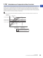
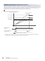
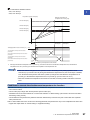
1.32
Simultaneous Temperature Rise Function . . . . . . . . . . . . . . . . . . . . . . . . . . . . . . . . . . . . . . . . . . . . . . . . . . . 95
1.33
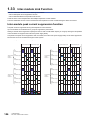
Inter-module Link Function . . . . . . . . . . . . . . . . . . . . . . . . . . . . . . . . . . . . . . . . . . . . . . . . . . . . . . . . . . . . . . 106
Inter-module peak current suppression function . . . . . . . . . . . . . . . . . . . . . . . . . . . . . . . . . . . . . . . . . . . . . . . . 106
Inter-module simultaneous temperature rise function . . . . . . . . . . . . . . . . . . . . . . . . . . . . . . . . . . . . . . . . . . . . 108
1.34
10
Proportional Band Setting Function . . . . . . . . . . . . . . . . . . . . . . . . . . . . . . . . . . . . . . . . . . . . . . . . . . . . . . . 110
1.35
Disturbance Suppression Function. . . . . . . . . . . . . . . . . . . . . . . . . . . . . . . . . . . . . . . . . . . . . . . . . . . . . . . . 111
1.36
Buffer Memory Data Backup Function . . . . . . . . . . . . . . . . . . . . . . . . . . . . . . . . . . . . . . . . . . . . . . . . . . . . . 117
1.37
Overshoot Suppression Function . . . . . . . . . . . . . . . . . . . . . . . . . . . . . . . . . . . . . . . . . . . . . . . . . . . . . . . . . 119
1.38
Error History Function . . . . . . . . . . . . . . . . . . . . . . . . . . . . . . . . . . . . . . . . . . . . . . . . . . . . . . . . . . . . . . . . . . 120
1.39
Event History Function . . . . . . . . . . . . . . . . . . . . . . . . . . . . . . . . . . . . . . . . . . . . . . . . . . . . . . . . . . . . . . . . . . 123
1.40
Interrupt Function . . . . . . . . . . . . . . . . . . . . . . . . . . . . . . . . . . . . . . . . . . . . . . . . . . . . . . . . . . . . . . . . . . . . . . 124
1.41
Q Compatible Mode Function. . . . . . . . . . . . . . . . . . . . . . . . . . . . . . . . . . . . . . . . . . . . . . . . . . . . . . . . . . . . . 127
CHAPTER 2
PARAMETER SETTING
128
2.1
Basic Setting . . . . . . . . . . . . . . . . . . . . . . . . . . . . . . . . . . . . . . . . . . . . . . . . . . . . . . . . . . . . . . . . . . . . . . . . . . 128
2.2
Application Setting . . . . . . . . . . . . . . . . . . . . . . . . . . . . . . . . . . . . . . . . . . . . . . . . . . . . . . . . . . . . . . . . . . . . . 129
2.3
CT Setting. . . . . . . . . . . . . . . . . . . . . . . . . . . . . . . . . . . . . . . . . . . . . . . . . . . . . . . . . . . . . . . . . . . . . . . . . . . . . 130
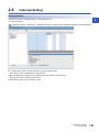
2.4
Interrupt Setting. . . . . . . . . . . . . . . . . . . . . . . . . . . . . . . . . . . . . . . . . . . . . . . . . . . . . . . . . . . . . . . . . . . . . . . . 131
Refresh Settings . . . . . . . . . . . . . . . . . . . . . . . . . . . . . . . . . . . . . . . . . . . . . . . . . . . . . . . . . . . . . . . . . . . . . . . 132
Refresh processing time . . . . . . . . . . . . . . . . . . . . . . . . . . . . . . . . . . . . . . . . . . . . . . . . . . . . . . . . . . . . . . . . . . 133
CHAPTER 3
3.1
TROUBLESHOOTING
134
Checks Using LEDs. . . . . . . . . . . . . . . . . . . . . . . . . . . . . . . . . . . . . . . . . . . . . . . . . . . . . . . . . . . . . . . . . . . . . 134
When the RUN LED flashes or turns off . . . . . . . . . . . . . . . . . . . . . . . . . . . . . . . . . . . . . . . . . . . . . . . . . . . . . . 134
When the ERR LED turns on. . . . . . . . . . . . . . . . . . . . . . . . . . . . . . . . . . . . . . . . . . . . . . . . . . . . . . . . . . . . . . . 134
CONTENTS
2.5
When the ALM LED turns on or flashes . . . . . . . . . . . . . . . . . . . . . . . . . . . . . . . . . . . . . . . . . . . . . . . . . . . . . . 135
When the HBA LED turns on. . . . . . . . . . . . . . . . . . . . . . . . . . . . . . . . . . . . . . . . . . . . . . . . . . . . . . . . . . . . . . . 135
3.2
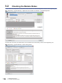
Checking the Module Status. . . . . . . . . . . . . . . . . . . . . . . . . . . . . . . . . . . . . . . . . . . . . . . . . . . . . . . . . . . . . . 136
3.3
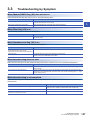
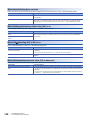
Troubleshooting by Symptom . . . . . . . . . . . . . . . . . . . . . . . . . . . . . . . . . . . . . . . . . . . . . . . . . . . . . . . . . . . . 137
3.4
List of Error Codes . . . . . . . . . . . . . . . . . . . . . . . . . . . . . . . . . . . . . . . . . . . . . . . . . . . . . . . . . . . . . . . . . . . . . 139
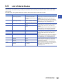
3.5
List of Alarm Codes. . . . . . . . . . . . . . . . . . . . . . . . . . . . . . . . . . . . . . . . . . . . . . . . . . . . . . . . . . . . . . . . . . . . . 143
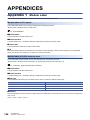
APPENDICES
144
Appendix 1 Module Label . . . . . . . . . . . . . . . . . . . . . . . . . . . . . . . . . . . . . . . . . . . . . . . . . . . . . . . . . . . . . . . . . . . . . 144
Appendix 2 I/O Signal . . . . . . . . . . . . . . . . . . . . . . . . . . . . . . . . . . . . . . . . . . . . . . . . . . . . . . . . . . . . . . . . . . . . . . . . 146
List of I/O signals . . . . . . . . . . . . . . . . . . . . . . . . . . . . . . . . . . . . . . . . . . . . . . . . . . . . . . . . . . . . . . . . . . . . . . . . 146
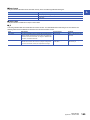
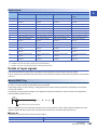
Details of input signals. . . . . . . . . . . . . . . . . . . . . . . . . . . . . . . . . . . . . . . . . . . . . . . . . . . . . . . . . . . . . . . . . . . . 147
Details of output signals . . . . . . . . . . . . . . . . . . . . . . . . . . . . . . . . . . . . . . . . . . . . . . . . . . . . . . . . . . . . . . . . . . 155
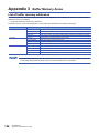
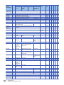
Appendix 3 Buffer Memory Areas. . . . . . . . . . . . . . . . . . . . . . . . . . . . . . . . . . . . . . . . . . . . . . . . . . . . . . . . . . . . . . . 158
List of buffer memory addresses . . . . . . . . . . . . . . . . . . . . . . . . . . . . . . . . . . . . . . . . . . . . . . . . . . . . . . . . . . . . 158
Details of buffer memory addresses . . . . . . . . . . . . . . . . . . . . . . . . . . . . . . . . . . . . . . . . . . . . . . . . . . . . . . . . . 202
Appendix 4 PID . . . . . . . . . . . . . . . . . . . . . . . . . . . . . . . . . . . . . . . . . . . . . . . . . . . . . . . . . . . . . . . . . . . . . . . . . . . . . . 310
PID control. . . . . . . . . . . . . . . . . . . . . . . . . . . . . . . . . . . . . . . . . . . . . . . . . . . . . . . . . . . . . . . . . . . . . . . . . . . . . 310
PID operation. . . . . . . . . . . . . . . . . . . . . . . . . . . . . . . . . . . . . . . . . . . . . . . . . . . . . . . . . . . . . . . . . . . . . . . . . . . 312
Actions of the temperature control module . . . . . . . . . . . . . . . . . . . . . . . . . . . . . . . . . . . . . . . . . . . . . . . . . . . . 313
Proportional action (P action) . . . . . . . . . . . . . . . . . . . . . . . . . . . . . . . . . . . . . . . . . . . . . . . . . . . . . . . . . . . . . . 314
Integral action (I action) . . . . . . . . . . . . . . . . . . . . . . . . . . . . . . . . . . . . . . . . . . . . . . . . . . . . . . . . . . . . . . . . . . . 315
Derivative action (D action) . . . . . . . . . . . . . . . . . . . . . . . . . . . . . . . . . . . . . . . . . . . . . . . . . . . . . . . . . . . . . . . . 316
PID action . . . . . . . . . . . . . . . . . . . . . . . . . . . . . . . . . . . . . . . . . . . . . . . . . . . . . . . . . . . . . . . . . . . . . . . . . . . . . 316
INDEX
317
REVISIONS . . . . . . . . . . . . . . . . . . . . . . . . . . . . . . . . . . . . . . . . . . . . . . . . . . . . . . . . . . . . . . . . . . . . . . . . . . . . .320
WARRANTY . . . . . . . . . . . . . . . . . . . . . . . . . . . . . . . . . . . . . . . . . . . . . . . . . . . . . . . . . . . . . . . . . . . . . . . . . . . .321
TRADEMARKS . . . . . . . . . . . . . . . . . . . . . . . . . . . . . . . . . . . . . . . . . . . . . . . . . . . . . . . . . . . . . . . . . . . . . . . . . .322
11
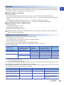
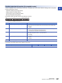
RELEVANT MANUALS
Manual name [manual number]
Description
Available form
MELSEC iQ-R Temperature Control Module User's
Manual (Application)
[SH-081536ENG] (this manual)
Functions, parameter settings, troubleshooting, I/O signals, and buffer memory
of the temperature control module
Print book
MELSEC iQ-R Temperature Control Module User's
Manual (Startup)
[SH-081535ENG]
Specifications, procedures before operation, wiring, and operation examples of
the temperature control module
Print book
e-Manual
EPUB
PDF
e-Manual
EPUB
PDF
e-Manual refers to the Mitsubishi FA electronic book manuals that can be browsed using a dedicated tool.
e-Manual has the following features:
• Required information can be cross-searched in multiple manuals.
• Other manuals can be accessed from the links in the manual.
• The hardware specifications of each part can be found from the product figures.
• Pages that users often browse can be bookmarked.
TERMS
Unless otherwise specified, this manual uses the following terms.
12
Term
Description
Buffer memory
The intelligent function module's memory where the data (including setting values and monitored values) received/sent
from/to the CPU module is stored
Control method
The generic term of two-position control, P control, PI control, PD control, and PID control
Control mode
The generic term of standard control, heating-cooling control (normal mode), heating-cooling control (expanded mode),
mix control (normal mode), mix control (expanded mode), position proportional control (normal mode), and position
proportional control (expanded mode)
CPU module
The generic term of MELSEC iQ-R series CPU modules
Engineering tool
The product name of the MELSEC programmable controller software package
PID constants
The generic term of the proportional band (P), integral time (I), and derivative time (D)
Q compatible mode
In this mode, the buffer memory map is converted into the one for the MELSEC-Q series and the module operates with
the buffer memory map.
R mode
In this mode, the module operates with the buffer memory map that has been newly assigned for the MELSEC iQ-R
series.
Simultaneous temperature rise
parameter
The generic term of simultaneous temperature rise dead time and simultaneous temperature rise gradient data
1
FUNCTIONS
1
This chapter describes the function details of the temperature control module.
For details on the I/O signals and buffer memory areas, refer to the following.
Page 147 Details of input signals
Page 155 Details of output signals
Page 202 Details of buffer memory addresses
This chapter describes the I/O signals and buffer memory addresses for CH1.
For details on the I/O signals for CH2 or later, refer to the following.
Page 146 List of I/O signals
For details on the buffer memory addresses for CH2 or later, refer to the following.
Page 158 List of buffer memory addresses
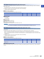
1.1
Control Mode Selection Function
A control mode can be selected using this function. This section describes control modes that can be selected for the
temperature control module.
Standard control, heating-cooling control, position proportional control
There are three types of control modes in the temperature control module: Standard control, heating-cooling control, and
position proportional control.
■Standard control
The control method is either one of heating (reverse action) or cooling (direct action). When the control method is heating, of
a heater for example, cooling is controlled by simply turning off the heating. When the control method is cooling, of cold water
for example, heating is controlled by simply turning off the cooling.
■Heating-cooling control
The control method is both heating and cooling. To heat up the target subject, its heating mean is turned on, and its cooling
mean is turned off. To cool down the target subject, its heating mean is turned off, and its cooling mean is turned on.
■Position proportional control
The control method is either one of heating (reverse action) or cooling (direct action). Fluid flow is controlled with an electricoperated valve, and the process amount of such as temperature is controlled.
1 FUNCTIONS
1.1 Control Mode Selection Function
13
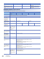
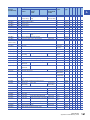
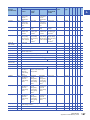
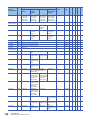
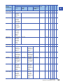
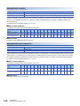
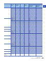
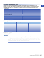
Selectable control mode
A control mode can be selected from the following seven modes. Select a control mode in "Control mode selection" of "Base
Setting".
Control mode
Description
No. of control loops
Standard control
Executes the standard control of four channels.
Standard control 4 loops
Heating-cooling control (normal mode)
Executes the heating-cooling control. CH3 and CH4 cannot be used.
Heating-cooling control 2 loops
Heating-cooling control (expanded mode)
Executes the heating-cooling control. The number of loops is expanded
using an output module and others in the system.
Heating-cooling control 4 loops
Mix control (normal mode)
Executes the standard control and the heating-cooling control. CH2
cannot be used.
• Standard control 2 loops
• Heating-cooling control 1 loops
Mix control (expanded mode)
Executes the standard control and the heating-cooling control. The
number of loops is expanded using an output module and others in the
system.
• Standard control 2 loops
• Heating-cooling control 2 loops
Position proportional control (normal
mode)
Executes the position proportional control. CH3 and CH4 cannot be used.
Position proportional control 2 loops
Position proportional control (expanded
mode)
Executes the position proportional control. The number of loops is
expanded using an output module and others in the system.
Position proportional control 4 loops
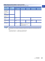
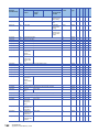
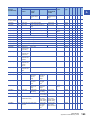
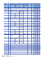
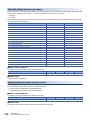
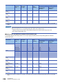
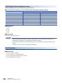
Control for each channel is as follows.
Channel
Standard
control
Heating-cooling control
Mix control
Normal mode
Expanded mode
Normal mode
Expanded mode
Normal mode
Expanded mode
CH1
Standard
control
Heating-cooling
control
Heating-cooling
control
Heating-cooling
control
Heating-cooling
control
Position
proportional control
Position
proportional control
CH2
Standard
control
Heating-cooling
control
Heating-cooling
control
*1
Heating-cooling
control
Position
proportional control
Position
proportional control
CH3
Standard
control
*1
Heating-cooling
control
Standard control
Standard control
*1
Position
proportional control
CH4
Standard
control
*1
Heating-cooling
control
Standard control
Standard control
*1
Position
proportional control
*1
Position proportional control
Only the temperature measurement using a temperature input terminal can be executed.
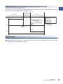
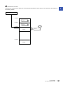
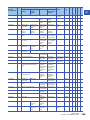
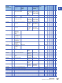
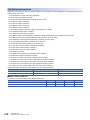
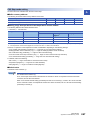
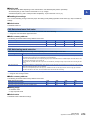
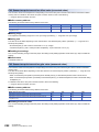
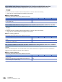
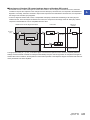
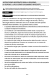
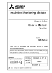
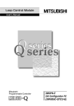
Expanded mode
In the heating-cooling control (expanded mode), mix control (expanded mode), or position proportional control (expanded
mode), the number of loops for the heating-cooling control or position proportional control can be expanded using an output
module and others in the system. To use an expanded mode, construct a system such as the one shown below.
CPU
module
4 channels
Temperature control module
Buffer memory
PID
operation
Temperature
process
CH Temperature
value (PV)
process value (PV)
(Un\G9, Un\G10,
Un\G11, Un\G12)
Manipulated
value for
heating
CH Manipulated
(MVh)
value for heating (MVh)
(Un\G13, Un\G14,
Un\G15, Un\G16)
Manipulated
value for
cooling
CH Manipulated
(MVc)
value for cooling (MVc)
(Un\G704, Un\G705,
Set value Un\G706, Un\G707)
(SV)
Initial setting
CH Set value
(SV) setting
(Un\G34, Un\G66,
Set value Un\G98, Un\G130)
(SV)
b0 of CH Heating
transistor output flag
(Un\G21, Un\G22,
Un\G23, Un\G24)
b0 of CH Cooling
transistor output flag
(Un\G712, Un\G713,
Un\G714, Un\G715)
CH1
CH1
CH2
CH2
CH3
CH3
CH4
CH1
Manipulated value CH4
for heating (MVh) L1H
CH2
L2H
Manipulated value
for cooling (MVc)
CH1
L1C
CH2
Heating
control
L2C
Cooling
control
Temperature
Object to be controlled
CH3
Heating
transistor output
Cooling transistor output
CH1
CH2
Output module in the same system
with the temperature control module
or on the same network with
the temperature control module
CH3
CH4
CH1
CH2
CH3
Heating
transistor output
Output signals
Y20
CH4
Y21
CH1
Y22
CH2
CH3
1 FUNCTIONS
1.1 Control Mode Selection Function
Cooling
transistor output
Y23
Y2F
Heating
control
Temperature
Object to be controlled
Cooling transistor output
CH4
CH4
14
Input from the temperature sensor
Heating
transistor
output
CH3
CH4
Input from the temperature sensor
Manipulated value
for heating (MVh)
TB1(L3H)
Manipulated value
for cooling (MVc)
TB3(L3C)
TB2(L4H)
TB4(L4C)
TB18
Cooling
control
1.2
Control Method
1
The following control methods can be achieved by setting a proportional band (P), integral time (I), and derivative time (D).
• Two-position control
• P control
• PI control
• PD control
• PID control
In the P control or PD control, the manual reset is enabled. ( Page 28 Manual Reset Function)
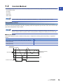
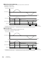
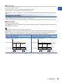
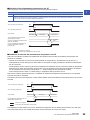
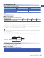
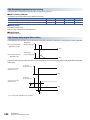
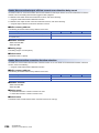
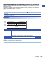
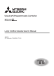
Two-position control
Two-position control is a control method that uses the 0% manipulated value (MV) and 100% manipulated value (MV).
Turning on and off the manipulated value (MV) repeatedly makes the temperature process value come close to the set value
(SV), and the temperature is kept constant.
By the setting in "Adjustment sensitivity (dead band) setting" of "Application Setting", the chattering of
transistor outputs under two-position control can be prevented. Configure the setting for the set value (SV).
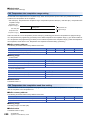
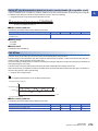
■Standard control
The module operates as follows outside the setting range of "Adjustment sensitivity (dead band) setting" in "Application
Setting".
Condition
Transistor output status
The temperature process value (PV) is below the lower limit of the adjustment
sensitivity (dead band).
ON
The temperature process value (PV) is above the upper limit of the adjustment
sensitivity (dead band).
OFF
Temperature
process value (PV)
Adjustment sensitivity
(dead band)
Set value (SV)
Time
ON
Transistor output
OFF
1 FUNCTIONS
1.2 Control Method
15
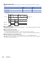
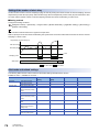
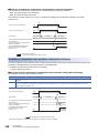
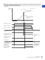
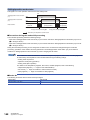
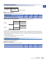
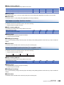
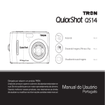
■Heating-cooling control
The module operates as follows outside the setting range of "Adjustment sensitivity (dead band) setting" in "Application
Setting".
Condition
Heating transistor output
status
Cooling transistor output
status
The temperature process value (PV) is below the lower limit of the adjustment
sensitivity (dead band).
ON
OFF
The temperature process value (PV) is above the upper limit of the adjustment
sensitivity (dead band).
OFF
ON
Temperature
process value (PV)
Adjustment sensitivity
(dead band)
Set value (SV)
Time
ON
Heating output
(L1H)
OFF
Cooling output
(L1C)
ON
OFF
■Three-position control
Three-position control can also be executed by setting a dead band. ( Page 27 Dead band setting in the two-position
control (three-position control))
■Setting method (in the R mode)
Set 0 (0 ()) in the following buffer memory areas.
• 'CH1 Proportional band (P) setting' (Un\G431) ( Page 233 CH1 Proportional band (P) setting)
• 'CH1 Heating proportional band (Ph) setting' (Un\G431) ( Page 235 CH1 Heating proportional band (Ph) setting)
■Setting method (in the Q compatible mode)
Set 0.0% for "Proportion Belt (P) Setting" of "Control basic parameters". ( Page 129 Application Setting)
[Navigation window] [Parameter] [Module Information] Target module [Module Parameter] [Application
Setting] [Control basic parameters]
16
1 FUNCTIONS
1.2 Control Method
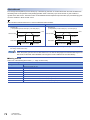
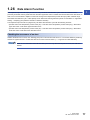
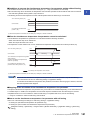
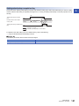
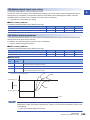
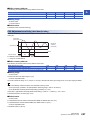
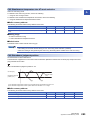
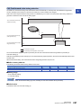
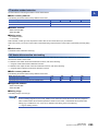
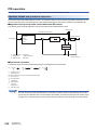
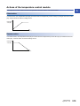
P control
1
P control is a control method in which the manipulated value (MV) is determined proportional to the deviation (E) between the
temperature process value (PV) and set value (SV).
■Standard control
The manipulated value (MV) is 50% in the following conditions.
• Temperature process value (PV) = Set value (SV)
• 'CH1 Manual reset amount setting' (Un\G517) has been set to 0 (0.0%) ( Page 258 CH1 Manual reset amount setting).
Manipulated value (MV)*1
100%
50%
Temperature process
value (PV)
0%
Set value (SV)*2
Proportional band (P)
*1
*2
A value to be actually output is within the output limiter range set in "Upper limit output limiter" and "Lower limit output limiter" of "Limiter
setting" in "Application Setting".
The set value (SV) is the center of the proportional band (P).
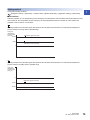
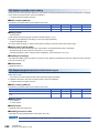
■Heating-cooling control
The manipulated value for heating (MVh) and the manipulated value for cooling (MVc) are both 0% in the following conditions.
• Temperature process value (PV) = Set value (SV)
• 'CH1 Manual reset amount setting' (Un\G517) has been set to 0 (0.0%) ( Page 258 CH1 Manual reset amount setting).
100%
Manipulated value
for heating (MVh)*1
Manipulated value
for cooling (MVc)*1
Temperature process
value (PV)
0%
Set value (SV)
Heating proportional
band (Ph)
*1
Cooling proportional
band (Pc)
A value to be actually output is within the output limiter range set in "Upper limit output limiter" and "Lower limit output limiter" of "Limiter
setting" in "Application Setting". ( Page 129 Application Setting)
■Setting method (in the R mode)
Set each item as follows.
• 'CH1 Proportional band (P) setting' (Un\G431): Any value ( Page 233 CH1 Proportional band (P) setting)
• 'CH1 Heating proportional band (Ph) setting' (Un\G431): Any value ( Page 235 CH1 Heating proportional band (Ph)
setting)
• 'CH1 Integral time (I) setting' (Un\G432): 0 (0s) ( Page 235 CH1 Integral time (I) setting)
• 'CH1 Derivative time (D) setting' (Un\G433): 0 (0s) ( Page 236 CH1 Derivative time (D) setting)
1 FUNCTIONS
1.2 Control Method
17
■Setting method (in the Q compatible mode)
Set each item as follows.
• "Proportion Belt (P) Setting": Any value
• "Integration Time (I) Setting": 0s
• "Differentiation Time (D) Setting": 0s
[Navigation window] [Parameter] [Module Information] Target module [Module Parameter] [Application
Setting] [Control basic parameters]
PI control
PI control is a control method in which derivative elements are added to P control, and thereby corrects an offset (remaining
deviation) that remains when the temperature is stable. By setting the integral time (I) properly, the temperature process value
(PV) matches with the set value (SV).
■Setting method (in the R mode)
Set each item as follows.
• 'CH1 Proportional band (P) setting' (Un\G431): Any value ( Page 233 CH1 Proportional band (P) setting)
• 'CH1 Heating proportional band (Ph) setting' (Un\G431): Any value ( Page 235 CH1 Heating proportional band (Ph)
setting)
• 'CH1 Integral time (I) setting' (Un\G432): Any value ( Page 235 CH1 Integral time (I) setting)
• 'CH1 Derivative time (D) setting' (Un\G433): 0 (0s) ( Page 236 CH1 Derivative time (D) setting)
■Setting method (in the Q compatible mode)
Set each item as follows.
• "Proportion Belt (P) Setting": Any value
• "Integration Time (I) Setting": Any value
• "Differentiation Time (D) Setting": 0s
[Navigation window] [Parameter] [Module Information] Target module [Module Parameter] [Application
Setting] [Control basic parameters]
PD control
PD control is a control method in which the derivative time (D) is set in addition to P control. The control mechanism is the
same as P control.
■Setting method (in the R mode)
Set each item as follows.
• 'CH1 Proportional band (P) setting' (Un\G431): Any value ( Page 233 CH1 Proportional band (P) setting)
• 'CH1 Heating proportional band (Ph) setting' (Un\G431): Any value ( Page 235 CH1 Heating proportional band (Ph)
setting)
• 'CH1 Integral time (I) setting' (Un\G432): 0 (0s) ( Page 235 CH1 Integral time (I) setting)
• 'CH1 Derivative time (D) setting' (Un\G433): Any value ( Page 236 CH1 Derivative time (D) setting)
■Setting method (in the Q compatible mode)
Set each item as follows.
• "Proportion Belt (P) Setting": Any value
• "Integration Time (I) Setting": 0s
• "Differentiation Time (D) Setting": Any value
[Navigation window] [Parameter] [Module Information] Target module [Module Parameter] [Application
Setting] [Control basic parameters]
18
1 FUNCTIONS
1.2 Control Method
PID control
1
PID control is a control method in which derivative elements are added to PI control, and thereby the temperature shifts to a
stable status in a short period of time even when a drastic change has occurred. By setting the derivative time (D) properly,
the controlled object shifts to a stable status in a short period of time.
■Setting method (in the R mode)
Set each item as follows.
• 'CH1 Proportional band (P) setting' (Un\G431): Any value ( Page 233 CH1 Proportional band (P) setting)
• 'CH1 Heating proportional band (Ph) setting' (Un\G431): Any value ( Page 235 CH1 Heating proportional band (Ph)
setting)
• 'CH1 Integral time (I) setting' (Un\G432): Any value ( Page 235 CH1 Integral time (I) setting)
• 'CH1 Derivative time (D) setting' (Un\G433): Any value ( Page 236 CH1 Derivative time (D) setting)
■Setting method (in the Q compatible mode)
Set each item as follows.
• "Proportion Belt (P) Setting": Any value
• "Integration Time (I) Setting": Any value
• "Differentiation Time (D) Setting": Any value
[Navigation window] [Parameter] [Module Information] Target module [Module Parameter] [Application
Setting] [Control basic parameters]
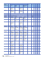
Condition to execute the PID control
Whether PID control is executed or not depends on the following settings:
• 'Setting/operation mode command' (Y1)
• "PID continuation Flag" of "Control basic parameters" in "Application Setting"
• 'CH1 PID control forced stop command' (YC)
• "Stop mode setting" of "Control basic parameters" in "Application Setting"
The following table shows the relation between each setting and the execution of PID control.
Executed: , Not executed:
'Setting/operation mode
command' (Y1)*2
"PID continuation Flag" of
"Control basic parameters"
in "Application Setting"
Setting mode at power-on
Operation mode (during operation)
Setting mode (after operation)
*1
*2
'CH1 PID control
forced stop
command' (YC)
"Stop mode setting" of
"Control basic parameters"
in "Application Setting"
Control status
of PID control*1
Stop (0), Continue (1)
OFF, ON
Stop (0), Monitor (1), Alert (2)
Stop (0), Continue (1)
OFF
Stop (0), Monitor (1), Alert (2)
ON
Stop (0), Monitor (1), Alert (2)
Stop (0)
OFF, ON
Stop (0), Monitor (1), Alert (2)
Continue (1)
OFF
Stop (0), Monitor (1), Alert (2)
ON
Stop (0), Monitor (1), Alert (2)
Here, this term is the generic term of two-position control, P control, PI control, PD control, and PID control.
For each timing, refer to the following.
Page 148 Setting/operation mode status
Even though the above conditions have been satisfied, PID control is not executed when "Unused channel setting" of "Control
basic parameters" in "Application Setting" has been set to "Unused (1)".
The manipulated value (MV) and the manipulated value (MV) for output with another analog module of when 'CH1 PID control
forced stop command' (YC) is turned off and on are as follows.
Buffer memory area name
Buffer memory address
Stored value
Reference
CH1 Manipulated value (MV)
403
-50 (-5.0%)
Page 221 CH1 Manipulated value (MV)
CH1 Manipulated value (MV) for
output with another analog module
407
0
Page 224 CH1 Manipulated value (MV)
for output with another analog module
CH1 Manipulated value for heating
(MVh)
403
-50 (-5.0%)
Page 221 CH1 Manipulated value for
heating (MVh)
CH1 Manipulated value for heating
(MVh) for output with another analog
module
407
0
Page 225 CH1 Manipulated value for
heating (MVh) for output with another
analog module
1 FUNCTIONS
1.2 Control Method
19
Buffer memory area name
Buffer memory address
Stored value
Reference
CH1 Manipulated value for cooling
(MVc)
408
-50 (-5.0%)
Page 222 CH1 Manipulated value for
cooling (MVc)
CH1 Manipulated value for cooling
(MVc) for output with another analog
module
409
0
Page 225 CH1 Manipulated value for
cooling (MVc) for output with another
analog module
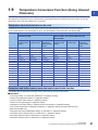
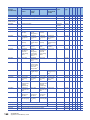
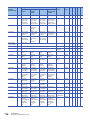
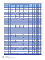
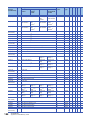
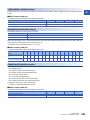
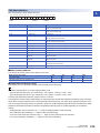
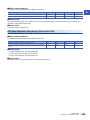
Parameters related to control methods
The following table shows the parameters related to each control method.
Parameter
Setting range
Two-position
control
Input range setting
20
P control
PD control
PI control
PID control
• Thermocouple: 1 to 4, 11 to 28, 36 to 52, 100 to 117, 130 to 132, 201 to 205
• Platinum resistance thermometer: 5 to 8, 53, 54, 140 to 143, 201 to 205
Set value (SV) setting
Set a value within the temperature measuring range of the set input range.
Proportional band (P)
setting, Cooling
proportional band (Pc)
setting (in the Q
compatible mode)
Fix the setting to 0.
0 to 10000 (0.0% to 1000.0%)
Integral time (I) setting
(in the Q compatible
mode)
A set value is ignored.
Fix the setting to 0.
Derivative time (D)
setting (in the Q
compatible mode)
A set value is ignored.
Fix the setting to 0.
Adjustment sensitivity
(dead band) setting
■In the R mode
0 to Full scale ( ())
■In the Q compatible
mode
0 to 10000 (0.0% to
1000.0%)
A set value is ignored.
Upper limit output
limiter, lower limit output
limiter (standard control
only)
A set value is ignored.
-50 to 1050 (-5.0% to 105.0%)
Upper limit output
limiter, cooling upper
limit output limiter
(heating-cooling control
only)
A set value is ignored.
0 to 1050 (0.0% to 105.0%)
Output variation amount
limiter
A set value is ignored.
1 to 1000 (1%/s to 100.0%/s)
Control output cycle
setting (standard control
only)
A set value is ignored.
The setting range depends on the control output cycle unit selection setting.
■When the control output cycle unit selection setting is 1s cycle (0)
• Setting range: 1 to 100 (s)
• Default value: 30 (s)
■When the control output cycle unit selection setting is 0.1s cycle (1)
• Setting range: 5 to 1000 (0.5 to 100.0s)
• Default value: 300 (30.0s)
Control output cycle
setting, cooling control
output cycle setting
(heating-cooling control
only)
A set value is ignored.
The setting range depends on the control output cycle unit selection setting.
■When the control output cycle unit selection setting is 1s cycle (0)
• Setting range: 1 to 100 (s)
• Default value: 30 (s)
■When the control output cycle unit selection setting is 0.1s cycle (1)
• Setting range: 5 to 1000 (0.5 to 100.0s)
• Default value: 300 (30.0s)
Overlap/dead band
setting
■In the R mode
(-(Full scale)) to Full
scale ( ())
■In the Q compatible
mode
-100 to 100 (-10.0% to
10.0%)
■In the R mode
(-(Full scale)) to Full scale ( ())
■In the Q compatible mode
-100 to 100 (-10.0% to 10.0%)
1 FUNCTIONS
1.2 Control Method
1 to 3600 (s)
1 to 3600 (s)
Fix the setting to 0.
1 to 3600 (s)
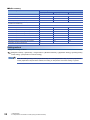
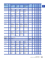
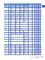
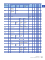
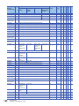
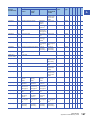
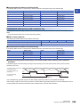
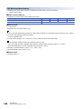
Buffer memory areas related to control methods
1
The following table shows the buffer memory areas related to each control method.
Buffer memory
area name
Buffer memory
address
Setting range
Two-position
control
P control
CH1 Proportional
band (P) setting,
CH1 Heating
proportional band
(Ph) setting (in the
R mode)
431
Fix the setting to 0.
0 to the full scale of the input range ( ())
CH1 Cooling
proportional band
(Pc) setting (in the
R mode)
439
CH1 Integral time (I)
setting (in the R
mode)
432
A set value is
ignored.
Fix the setting to 0.
CH1 Derivative time
(D) setting (in the R
mode)
433
A set value is
ignored.
Fix the setting to 0.
CH1 Manual reset
amount setting
517
A set value is
ignored.
■In the standard control or heating-cooling
control
• Setting range: -1000 to 1000 (-100.0% to
100.0%, in increments of 0.1%)
• Default value: 0 (0%)
PD control
P control
PID control
1 to 3600 (s)
1 to 3600 (s)
A set value is
ignored.
1 to 3600 (s)
A set value is ignored.
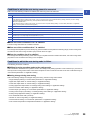
The temperature control module automatically sets optimum PID constants when the following functions are
used.
• Auto Tuning Function ( Page 34 Auto Tuning Function)
• Self-Tuning Function ( Page 42 Self-tuning Function)
1 FUNCTIONS
1.2 Control Method
21
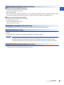
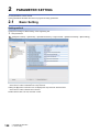
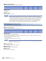
1.3
Sampling Cycle Switching Function
In the temperature control module, a measured temperature value is stored into 'CH1 Temperature process value (PV)'
(Un\G402) every sampling cycle. In addition, the use of the primary delay digital filter smoothens the temperature process
value (PV), and its drastic change can be absorbed.
Sampling cycle
Select 250ms or 500ms as a sampling cycle.
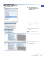
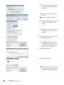
■How to set the sampling cycle
Configure the setting as follows.
[Navigation window] [Parameter] Target module [Module Parameter] [Base Setting] [Sampling cycle
selection]
■How to check the sampling cycle
The sampling cycle in execution can be checked in 'Sampling cycle monitor' (Un\G38).
1.4
Control Output Cycle Unit Selection Function
This function is used to switch the unit for the control output cycle between 1s and 0.1s. When 0.1s is set as the control output
cycle, more precise control can be executed.
The control output cycle is the ON/OFF cycle of transistor output for the temperature control function.
Setting method
Configure the setting as follows.
[Navigation window] [Parameter] Target module [Module Parameter] [Base Setting] [Control output cycle
unit selection setting]
• The setting range and default value of the control output cycle depends on this setting. ( Page 215
Control output cycle unit selection setting)
• A setting value discrepancy error (error code: 1920H) occurs right after changing this setting. To recover
from the error status, turn on and off Set value backup instruction (Y8). Then, register the new setting in the
non-volatile memory.
22
1 FUNCTIONS
1.3 Sampling Cycle Switching Function
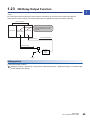
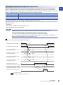
1.5
HOLD/CLEAR Function
1
Whether to clear or hold the transistor output status when a CPU stop error occurs or when a CPU module is turned from
RUN to STOP can be selected.
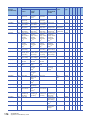
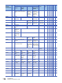
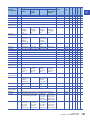
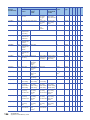
Standard control, heating-cooling control, mix control
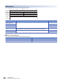
The following shows the relation among the setting, error, and the operation of the CPU module.
Status
Processing
HOLD/CLEAR setting
CLEAR
HOLD
PID continuation flag
Stop
CPU module
status
RUN
The temperature judgment and warning judgment are executed and the external output is executed.
Continue
Stop
Continue
Stop error
The temperature judgment and warning judgment stop and
the external output is turned off.
The temperature judgment and
warning judgment depend on
the stop mode setting of "Control
basic parameters" in
"Application Setting" and the
external output are turned off.
The temperature
judgment and warning
judgment are executed
and the external output
is executed.
Operation of the
CPU module
RUNSTOP
The temperature judgment and
warning judgment depend on the
stop mode setting of "Control
basic parameters" in "Application
Setting" and the external output
are turned off.
The temperature
judgment and warning
judgment are executed
and the external output
is executed.
The temperature judgment and
warning judgment depend on
the stop mode setting of "Control
basic parameters" in
"Application Setting" and the
external output are turned off.
The temperature
judgment and warning
judgment are executed
and the external output
is executed.
Resetting
The module is inoperative, and does not execute external outputs.
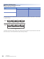
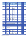
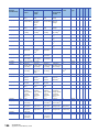
Position proportional control
The following shows the relation among the setting, error, and the operation of the CPU module.
Status
Processing
HOLD/CLEAR setting
CLEAR
PID continuation flag
Stop
HOLD
Continue
Stop
Continue
CPU module
status
RUN
The temperature judgment and warning judgment are executed and the external output is executed.
Stop error
The temperature judgment and warning judgment stop and
the external output is turned off.
The temperature judgment and
warning judgment depend on the
stop mode setting of "Control
basic parameters" in "Application
Setting", and the external output
depends on "Valve operation
setting (When CPU stop)".
The temperature
judgment and warning
judgment are executed
and the external output
is executed.
Operation of the
CPU module
RUNSTOP
The temperature judgment and
warning judgment depend on the
stop mode setting of "Control
basic parameters" in "Application
Setting", and the external output
depends on "Valve operation
setting (When CPU stop)".
The temperature
judgment and warning
judgment are executed
and the external output
is executed.
Resetting
The module is inoperative, and does not execute external outputs.
Precautions
• Fully pay attention to the settings of "PID continuation Flag" of "Control basic parameters" in "Application Setting" and
"Valve operation setting (When CPU stop)" of "Position-proportional control setting" in "Application Setting" for controlling
external outputs.
• Depending on an output element failure or an internal circuit failure, an abnormal output may occur. Configure an external
circuit for monitoring output signals that could cause a serious accident.
1 FUNCTIONS
1.5 HOLD/CLEAR Function
23
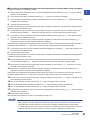
Setting method
Configure the setting as follows.
[Navigation window] [Parameter] Target module [Module Parameter] [Base Setting] [HOLD/CLEAR setting]
24
1 FUNCTIONS
1.5 HOLD/CLEAR Function
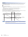
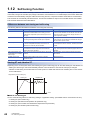
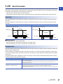
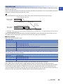
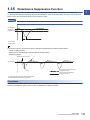
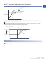
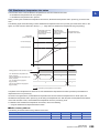
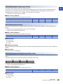
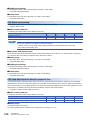
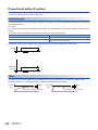
1.6
Overlap/dead Band Function
1
In the heating-cooling control, the temperature process value (PV) significantly changes due to a slight heating or cooling
control output when the heat produced by a controlled object and natural cooling are being balanced. Consequently, an
excessive output may be executed.
The temperature where the cooling control output starts can be shifted using this function; therefore, whether control stability
is prioritized or energy saving is prioritized can be selected.
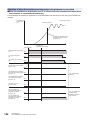
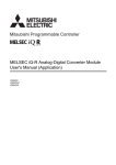
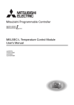
Overlap
The overlap refers to the temperature area where both of heating control and cooling control are executed. In the temperature
area where both heating and cooling output overlap, both of the outputs negate each other. Thus, the control gain becomes
moderate. Consequently, the variation amount in the temperature process value (PV) for the output becomes small, improving
control stability.
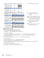
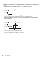
Ex.
When the following values have been set:
• "Input range setting" of "Control basic parameters" in "Application Setting": 38 (Temperature measuring range: -200.0 to
400.0)
• "Target Value(SV) Setting" of "Control basic parameters" in "Application Setting": 200.0
• "Overlap/dead band setting" of "Heating/cooling control setting" in "Application Setting": -15.0
The range of 185.0 to 200.0 is the overlapping area.
The temperature where a cooling operation starts = (Set value (SV)) - 15.0 = 185.0
As shown below, shifting the temperature where a cooling operation starts to the lower temperature side of the set value (SV)
produces an overlapping area. (The following is an example of when the module is in P control.)
Heating only
(manipulated value for cooling (MVc): 0%)
Heating/Cooling
Cooling only
(manipulated value for heating (MVh): 0%)
100%
Heating
Temperature
process value (PV)
0%
Set value (SV) is 200.0
Cooling starts at 185.0
.
.
Cooling
-100%
In the Q compatible mode, set -2.5% for "Overlap/dead band setting" of "Heating/cooling control setting" in
"Application Setting". (400 - (-200)) (-0.025) = -15
1 FUNCTIONS
1.6 Overlap/dead Band Function
25
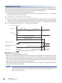
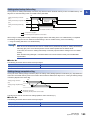
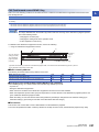
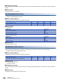
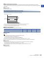
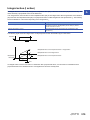
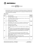
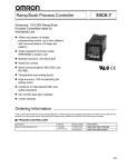
Dead band
The dead band refers to the temperature area where neither heating control output nor cooling control output is executed.
When the temperature process value (PV) is stable within this area, output is not executed for a slight change in the
temperature, resulting in energy saving.
Ex.
When the following values have been set:
• "Input range setting" of "Control basic parameters" in "Application Setting": 38 (Temperature measuring range: -200.0 to
400.0)
• "Target Value(SV) Setting" of "Control basic parameters" in "Application Setting": 200.0
• "Overlap/dead band setting" of "Heating/cooling control setting" in "Application Setting": 15.0
The range of 200.0 to 215.0 is the dead band area.
The temperature where a cooling operation starts = (Set value (SV)) + 15.0 = 215.0
As shown below, shifting the temperature where a cooling operation starts to the lower temperature side of the set value (SV)
produces a dead band area. (The following is an example of when the module is in P control.)
Manipulated value
for heating (MVh): 0%
Heating only
(manipulated value for cooling (MVc): 0%)
Manipulated value
for cooling (MVc): 0%
Cooling only
(manipulated value for heating (MVh): 0%)
100%
Cooling starts at 215.0
Heating
.
Temperature
process value (PV)
0%
Set value (SV) is 200.0
.
Cooling
-100%
In the Q compatible mode, set 2.5% for "Overlap/dead band setting" of "Heating/cooling control setting" in
"Application Setting". (400 - (-200)) 0.025 = 15
26
1 FUNCTIONS
1.6 Overlap/dead Band Function
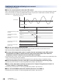
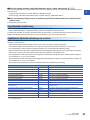
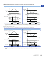
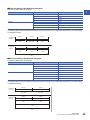
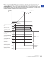
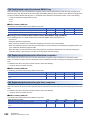
Dead band setting in the two-position control (three-position control)
1
Set the dead band in the two-position control.
Three-position control can be achieved by setting a dead band area in addition to areas for the manipulated value for heating
(MVh) 100% and the manipulated value for cooling (MVc) 100%.
Manipulated value
for heating (MVh): 0%
Heating only
(manipulated value for cooling (MVc): 0%)
Cooling only
Manipulated value
for cooling (MVc): 0% (manipulated value for heating (MVh): 0%)
100%
Heating
Temperature when
cooling starts
Heating proportional band (Ph): 0
Cooling proportional band (Pc):
No setting required
Integral time (I):
No setting required
Derivative time (D):
No setting required
Temperature
process value (PV)
0%
Set value (SV)
Cooling
-100%
Input range
Setting method
Configure the setting as follows.
[Navigation window] [Parameter] Target module [Module Parameter] [Application Setting] [Heating/cooling
control setting] [Overlap/dead band setting]
1 FUNCTIONS
1.6 Overlap/dead Band Function
27
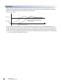
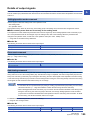
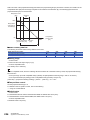
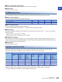
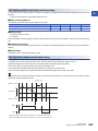
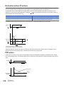
1.7
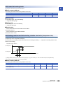
Manual Reset Function
This function is used to manually move a stable position in the P control or PD control.
An offset (remaining deviation) is manually reset by moving the proportional band (P).
The offset is reset by determining and setting the amount to shift the manipulated value (MV) in a stable condition from the
reference value.
The reference value is 50% for the standard control, and 0% for the heating-cooling control.
This function can be used only in the P control and PD control. This function is disabled when the integral time
(I) is set to a value other than 0.
'CH1 Manual reset amount setting' (Un\G517) is ignored even though a value has been set. (However, when
a value out of the setting value is set, an out of setting range error (error code: 1950H) occurs.)
Standard control
The set value (SV) is set at a point where the manipulated value (MV) is 50%. Thus, as long as the temperature process value
(PV) and the set value (SV) are not balanced at 50% of the manipulated value (MV), an offset (remaining deviation) is
generated.
When an offset is generated, the proportional band (P) can be manually shifted by the amount of the offset (remaining
deviation).
Ex.
When using the manual reset function in the following conditions
• Control method: P control
• 'CH1 Manual reset amount setting' (Un\G517): 300 (30%)
The temperature control module shifts the manipulated value (MV) in a stable condition at the set value (SV) from 50% to
80%.
Proportional band
(P)
(Percentage to the full scale)
Configure the settings
as follows:
Integral time (I): 0
Derivative time (D): 0
Manual reset
100%
The manipulated value (MV)
can be moved from 50% to 80%
to keep the set value (SV) stable.
80%
Manipulated value
(MV)
50%
0%
Set value (SV)
Manual reset range: -100.0 to 100.0% (every 0.1%)
(Set -1000 to 1000)
Input range
28
1 FUNCTIONS
1.7 Manual Reset Function
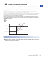
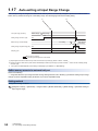
Heating-cooling control
1
The set value (SV) is set at a point where the manipulated value for heating (MVh)/manipulated value for cooling (MVc) is 0%.
Thus, as long as the temperature process value (PV) and the set value (SV) are not balanced at 0% of the manipulated value
for heating (MVh)/manipulated value for cooling (MVc), an offset (remaining deviation) is generated. When an offset is
generated, the heating proportional band (Ph)/cooling proportional band (Pc) can be manually shifted by the amount of the
offset (remaining deviation).
Ex.
When using the manual reset function in the following conditions
• Control method: P control
• 'CH1 Manual reset amount setting' (Un\G517): 800 (80%)
The temperature control module shifts the manipulated value (MV) in a stable condition at the set value (SV) from 0% to 80%.
Overlap/dead band
Heating proportional
band (Ph)
Cooling proportional
band (Pc)
(Percentage to the full scale)
100%
(Percentage to the full scale)
Heating: 100%
80%
Configure the settings
as follows:
Integral time (I): 0
Derivative time (D): 0
Heating
Manipulated value
for heating (MVh)
Manual reset
Heating: 0%
0%
The manipulated
value for heating (MVh)
can be moved from 0%
to 80% to keep
the set value (SV) stable.
Cooling: 0%
Set value (SV)
Cooling
Manipulated value
for cooling (MVc)
Cooling: 100%
-100%
Manual reset range: -100.0 to 100.0% (every 0.1%)
(Set -1000 to 1000)
Input range
Setting method
Set a value in the following buffer memory area.
'CH1 Manual reset amount setting' (Un\G517) ( Page 258 CH1 Manual reset amount setting)
1 FUNCTIONS
1.7 Manual Reset Function
29
1.8
Cooling Method Setting Function
At the execution of auto tuning, an auto tuning operational expression is automatically selected depending on a selected
cooling method and an operation is started.
Select one of the following methods:
• Air cooling: Select this method when cooling characteristics are a non-linear shape and cooling capacity is low.
• Water cooling: Select this method when cooling characteristics are a non-linear shape and cooling capacity is high.
• Linear: Select this method when cooling characteristics are close to a linear shape.
Cooling characteristics (rate
of when the manipulated value
for cooling (MVc) 100% is 1)
Cooling system and cooling characteristics
1
Water-cooling
Devices such as
cooling water piping
0.8
Air-cooling
0.6
Devices such as
cooling fans
0.4
Linear
Devices such as
electron coolers
0.2
Complete linear
characteristics
0
0
10
20
30
40
50
60
70
80
Manipulated value for cooling (MVc) (%)
90
100
At the execution of the auto tuning, PID constants are calculated based on this setting and the auto tuning is executed.
Therefore, more suitable PID constants can be calculated by the setting according to the cooling characteristics of the device.
For details on the auto tuning function, refer to the following.
Page 34 Auto Tuning Function
Setting method
Configure the setting as follows.
[Navigation window] [Parameter] Target module [Module Parameter] [Application Setting] [Heating/cooling
control setting] [Cooling method setting]
• An operational expression of the auto tuning for the calculation of PID constants is determined based on this
setting. Thus, always configure this setting before the execution of the auto tuning.
• Air cooling and water cooling roughly indicate the level of the cooling ability. When a device is too cooled
even though air cooling has been selected, set Water cooling (1H). When a device is less likely to be cooled
even though water cooling has been selected, set Air cooling (0H).
• Generally, the ability of water cooling is higher than that of air cooling and cooling may be too strong when
the same PID constants as the one for air cooling are used for water cooling. It takes time until the control
becomes stable upon the first start-up, disturbance, or setting change. Therefore, the auto tuning calculates
PID constants so that the PID constants of when Water cooling (1H) is set become larger than the ones of
when Air cooling (0H) is set.
30
1 FUNCTIONS
1.8 Cooling Method Setting Function
1.9
Temperature Conversion Function (Using Unused
Channels)
1
In the heating-cooling control (normal mode), mix control (normal mode), or position proportional control (normal mode), only
the temperature measurement can be executed using unused temperature input terminals. When this function is used, the
temperature control and alert judgment are not executed.
Temperature input terminals that can be used
Temperature input terminals that can be used for this function differ depending on the control mode to be selected.
Use the MT2 (Monitor CH2), MT3 (Monitor CH3), and MT4 (Monitor CH4) terminals in the following table.
Terminal No.
Terminal symbol
When using thermocouples (R60TCTRT2TT2,
R60TCTRT2TT2BW)
When using platinum resistance thermometers
(R60TCTRT2TT2, R60TCTRT2TT2BW, R60TCRT4,
R60TCRT4BW)
Heating-cooling
control (normal
mode)
Heating-cooling
control (normal
mode)
Mix control
(normal mode)
Position
proportional
control (normal
mode)
Mix control
(normal mode)
Position
proportional
control (normal
mode)
1
L1H
L1
CH1 OPEN
L1H
L1H
CH1 OPEN
2
L1C
L2
CH1 CLOSE
L1C
L1C
CH1 CLOSE
3
L2H
L3H
CH2 OPEN
L2H
L3
CH2 OPEN
4
L2C
L3C
CH2 CLOSE
L2C
L4
CH2 CLOSE
5
COM-
COM-
COM-
COM-
COM-
COM-
6
NC/CH2A
NC/MT2A
NC/CH2A
Not used
Not used
NC
7
CH1+/CH1B
CH1+/CH1B
CH1+/CH1B
CH1A
CH1A
CH1A
8
CH2+/CH2B
MT2+/MT2B
CH2+/CH2B
CH2A
MT2A
CH2A
9
CH1-/CH1b
CH1-/CH1b
CH1-/CH1b
CH1B
CH1B
CH1B
10
CH2-/CH2b
MT2-/MT2b
CH2-/CH2b
CH2B
MT2B
CH2B
11
NC/CH1A
NC/CH1A
NC/CH1A
CH1b
CH1b
CH1b
12
CJ
CJ
CJ
CH2b
MT2b
CH2b
13
NC
NC
NC
MT3A
CH3A
MT3A
14
CJ
CJ
CJ
MT4A
CH4A
MT4A
15
MT3+
CH3+
MT3+
MT3B
CH3B
MT3B
16
MT4+
CH4+
MT4+
MT4B
CH4B
MT3B
17
MT3-
CH3-
MT3-
MT3b
CH3b
MT3b
18
MT4-
CH4-
MT4-
MT4b
CH4b
MT4b
Parameters and buffer memory areas that can be used in this function
The following lists the parameters and buffer memory areas that can be used in this function.
■Parameter
• "Input range setting" of "Control basic parameters" in "Application Setting"
• "Primary Delay Digital Filter Setting" in "Application Setting"
• "Sensor Correction Value Setting" in "Application Setting"
• "Number of moving averaging" in "Application Setting"
• "Temperature conversion setting" of "Heating/cooling control setting" in "Application Setting"
• "Cold Junction Temperature Compensation Selection" in "Application Setting" (the R60TCTRT2TT2 and
R60TCTRT2TT2BW only)
• "Rate alarm alert output enable/disable setting" of "Rate alarm" in "Application Setting"
• "Rate alarm warning detection period" of "Rate alarm" in "Application Setting"
• "Rate alarm upper limit value" of "Rate alarm" in "Application Setting"
• "Rate alarm lower limit value" of "Rate alarm" in "Application Setting"
1 FUNCTIONS
1.9 Temperature Conversion Function (Using Unused Channels)
31
■Buffer memory
Buffer memory area name
Buffer memory address
MT2(CH2)
MT3(CH3)
MT4(CH4)
Latest error code
0
CH Decimal point position
600
800
1000
CH Alert definition
601
801
1001
CH1 Temperature process value (PV)
602
802
1002
Cold junction temperature process value (the R60TCTRT2TT2
and R60TCTRT2TT2BW only)
45
Control mode selection monitor
37
CH Sensor two-point correction offset value (measured value)
768
968
1168
CH Sensor two-point correction offset value (corrected value)
769
969
1169
CH Sensor two-point correction gain value (measured value)
770
970
1170
CH Sensor two-point correction gain value (corrected value)
771
971
1171
CH Sensor two-point correction offset latch request
766
966
1166
CH Sensor two-point correction offset latch completion
619
819
1019
CH Sensor two-point correction gain latch request
767
967
1167
CH Sensor two-point correction gain latch completion
620
820
1020
Temperature conversion completion flag
43
Setting method
Configure the setting as follows.
[Navigation window] [Parameter] Target module [Module Parameter] [Application Setting] [Heating/cooling
control setting] [Temperature conversion setting]
When the heating-cooling control (expanded mode), mix control (expanded mode), or position-proportional
control (expanded mode) has been selected, the setting of "Temperature conversion setting" is ignored.
32
1 FUNCTIONS
1.9 Temperature Conversion Function (Using Unused Channels)
1.10
Manual Control
1
A manipulated value (MV) can be set manually by users without being automatically calculated by the PID control.
The manipulated value (MV) is checked every 250ms or 500ms and reflected to the transistor output.
Select 250ms or 500ms in "Sampling cycle selection" of "Base Setting".
Setting method
Configure the setting by the following procedure.
1.
2.
Set 'CH1 AUTO/MAN mode shift' (Un\G518) to Manual (MAN) (1). ( Page 258 CH1 AUTO/MAN mode shift)
Check that MAN mode completed (1) has been stored in 'MAN mode shift completion flag' (Un\G44). ( Page 205
MAN mode shift completion flag)
3.
Set the manipulated value (MV) in 'CH1 MAN output setting' (Un\G519). ( Page 259 CH1 MAN output setting)
Setting range
The setting range differs between the standard control and heating-cooling control.
• Standard control: -50 to 1050 (-5.0 to 105.0%)
• Heating-cooling control: -1050 to 1050 (-105.0 to 105.0%)
1 FUNCTIONS
1.10 Manual Control
33
1.11
Auto Tuning Function
The temperature control module automatically sets the best PID constants. In the auto tuning, the control output is turned on
and off, and PID constants are calculated depending on the hunting cycle and amplitude that occur when overshoots and
undershoots of the temperature process value (PV) to the set value (SV) are repeated.
Auto tuning operation
The temperature control module operates as follows.
Temperature process
value (PV)
(2)
(4)
Set value (SV)
(Temperature process value (PV))
(1)
Time
(3)
Auto tuning in execution
Temperature
control
ON
‘CH1 Auto tuning command’
(Y4)
OFF
ON
‘CH1 Auto tuning status’
(X4)
OFF
Executed in a program
Executed by the temperature control module
(1)
(2)
(3)
(4)
The module starts the auto tuning.
The first overshoot and undershoot are ignored.
The module collects data from the point where the temperature process value (PV) reaches the set value (SV) after the first overshoot and undershoot.
The module ends the auto tuning when PID constants and the loop disconnection detection judgment time are set after the data collection.
The time taken for the auto tuning depends on a controlled object.
34
1 FUNCTIONS
1.11 Auto Tuning Function
Settings related to the auto tuning
1
The auto tuning can be executed when the following setting have been configured. Configure the other settings to the values
used for actual operations because actual control starts on completion of the auto tuning.
When "0" has been set for 'CH1 Proportional band (P) setting' (Un\G431) or 'CH1 Heating proportional band (Ph) setting'
(Un\G431), auto tuning is not executed.
• "Input range setting" of "Control basic parameters" in "Application Setting"
• "Target Value(SV) Setting" of "Control basic parameters" in "Application Setting"
• "Upper limit output limiter" of "Limiter setting" in "Application Setting"
• "Lower limit output limiter" of "Limiter setting" in "Application Setting"
• "Cooling upper limit output limiter" of "Heating/cooling control setting" in "Application Setting"
• "Output Change Amount Limiter" of "Limiter setting" in "Application Setting"
• "Sensor Correction Value Setting" in "Application Setting"
• "Control output cycle setting" of "Control basic parameters" in "Application Setting"
• "Primary Delay Digital Filter Setting" in "Application Setting"
• 'CH1 AUTO/MAN mode shift' (Un\G518)
• "AT Bias" of "Auto tuning setting" in "Application Setting"
• "Normal Operation/Reverse Operation Setting" in "Application Setting"
• "Auto tuning mode setting" of "Auto tuning setting" in "Application Setting"
For the system in which a temperature quickly rises, set the upper limit output limiter. Set a value twice as
large as the manipulated value (MV) in a stable state as a guide. After the completion of the auto tuning, the
output limiter can be returned to its initial value to start the control.
Storing the calculation values after auto tuning
After the completion of the auto tuning, calculation values are stored into the following buffer memory areas.
• 'CH1 Proportional band (P) setting' (Un\G431)
• 'CH1 Heating proportional band (Ph) setting' (Un\G431)
• 'CH1 Cooling proportional band (Pc) setting' (Un\G439)
• 'CH1 Integral time (I) setting' (Un\G432)
• 'CH1 Derivative time (D) setting' (Un\G433)
• 'CH1 Loop disconnection detection judgment time' (Un\G537)*1
*1
A value that is twice as large as the value in 'CH1 Integral time (I) setting' (Un\G432) is automatically set. However, when this setting has
been set to 0s at the auto tuning, the loop disconnection detection judgment time is not stored.
1 FUNCTIONS
1.11 Auto Tuning Function
35
Backing up calculation values at the completion of the auto tuning
When the following setting has been configured to "Valid" at the start of the auto tuning, values are automatically backed up in
the non-volatile memory.
[Navigation window] [Parameter] [Module Information] Target module [Application Setting] [Auto tuning
setting] [Automatic backup setting after auto tuning of PID constants]
To read the calculation value from the non-volatile memory to the buffer memory, set 'CH1 Memory's PID constants read
command' (Un\G440) to Requested (1). ( Page 239 CH1 Memory's PID constants read command)
To use the PID constants stored in the buffer memory in the Q compatible mode even after power-off, follow
the methods below.
• Use the initial setting of the engineering tool. ( Page 128 PARAMETER SETTING)
• Store the PID constants in the non-volatile memory, and transfer them when the power is turned off and on
or when the CPU module is reset and the reset is cleared. ( Page 117 Buffer Memory Data Backup
Function)
• Write the values directly into the buffer memory using a program.
Precautions
When the auto tuning is executed with the engineering tool, the memory having the capacity of 700MB or larger is required.
Check the memory that can be used has the capacity of 700MB or larger and execute the auto tuning.
36
1 FUNCTIONS
1.11 Auto Tuning Function
Procedure of auto tuning
1
■When using the engineering tool
[Tool] [Module Tool List]
1.
Select "Temperature trace" of
"Temperature Control Module" and
click the [OK] button.
2.
Select the module to configure the
temperature control setting and click
the [OK] button.
3.
Select "Monitor data write" from the
following.
[Setting] [Monitor data write]
4.
Select the parameter to be changed
from "Add to" to click the button.
5.
6.
The parameter is added in "View".
Click the [OK] button.
1 FUNCTIONS
1.11 Auto Tuning Function
37
7.
Write the set value to be changed.
8.
Set "Setting/Operation mode
command" to "1: Operation mode
command".
9. Set "Auto tuning command" to "1: ON".
10. When "Auto tuning command" is set to
"1: ON", "Auto tuning status" becomes
"Executing" and the auto tuning starts.
11. When the auto tuning is completed,
"Auto tuning status" becomes
"Stopped".
12. The temperature control is executed
with the set PID constants.
■When using a program
The auto tuning is executed by the following procedure.
1.
Setting each data in the temperature control module
Set each data. ( Page 35 Settings related to the auto tuning)
2.
Operation mode setting
• Turn off and on 'Setting/operation mode command' (Y1). ( Page 155 Setting/operation mode command)
• Check that 'Setting/operation mode status' (X1) is on. ( Page 148 Setting/operation mode status)
3.
Starting the auto tuning
Turn off and on 'CH1 Auto tuning command' (Y4). ( Page 155 Auto tuning command)
4.
During auto tuning
'CH1 Auto tuning status' (X4) is on. ( Page 150 Auto tuning status)
5.
After the completion of the auto tuning (setting PID constants)
'CH1 Auto tuning status' (X4) turns off and calculation values are set in the buffer memory. ( Page 35 Storing the
calculation values after auto tuning)
6.
Temperature control with the set PID constants
The temperature control is executed with the set PID constants.
38
1 FUNCTIONS
1.11 Auto Tuning Function
Conditions in which the auto tuning cannot be executed
1
When one of the following conditions is satisfied, the auto tuning cannot be executed.
Condition
1
The module is in the setting mode ('Setting/operation mode status' (X1): Off).
2
■In the R mode
In the standard control or heating-cooling control, 0 (0 ()) has been set for 'CH1 Proportional band (P) setting' (Un\G431) and 'CH1 Heating
proportional band (Ph) setting' (Un\G431). (The two-position control has been applied.)
■In the Q compatible mode
In the standard control or heating-cooling control, 0% has been set for "Proportion Belt (P) Setting" of "Control basic parameters" in "Application
Setting". (The two-position control has been applied.)
3
'CH1 AUTO/MAN mode shift' (Un\G518) has been set to MAN (1).
4
"Unused" has been set for the corresponding channels in "Unused channel setting" of "Control basic parameters" in "Application Setting".
5
'CH1 PID control forced stop command' (YC) is on.
6
A hardware failure has occurred. (The ERR LED is on.)
7
The value in 'CH1 Temperature process value (PV)' (Un\G402) has exceeded the temperature measuring range. (CH1 Input range upper limit
(Un\G401, b0) or CH1 Input range lower limit (Un\G401, b1) is on.)
8
'CH1 Memory's PID constants read command' (Un\G440) has been set to Requested (1).
9
CH1 Write completion flag (Un\G47, b0) is on.
■When one of the conditions 1 to 5 is satisfied
The auto tuning starts when the condition is cleared.
■When one of the conditions 6 to 7 is satisfied
Even though the temperature process value (PV) goes back within the temperature measuring range, the auto tuning does
not start until 'CH1 Auto tuning command' (Y4) is turned off and on again.
■When the condition 8 or 9 is satisfied
Even though the internal processing of the auto tuning is completed and PID constants are stored, 'CH1 Auto tuning status'
(X4) does not turn off and the auto tuning is not completed.
Conditions in which the auto tuning ends in failure
The following shows the conditions.
■Shifting from the operation mode to the setting mode
When the mode is shifted from the operation mode to the setting mode ('Setting/operation mode command' (Y1) is turned on
and off), the auto tuning ends in failure. Note that an exception is when "Continue" has been set for "PID continuation Flag" of
"Control basic parameters" in "Application Setting.
■Setting change during auto tuning
When the following settings are changed during auto tuning, the auto tuning ends in failure.
• "Target Value(SV) Setting" of "Control basic parameters" in "Application Setting"
• "Upper limit output limiter" of "Limiter setting" in "Application Setting"
• "Lower limit output limiter" of "Limiter setting" in "Application Setting"
• "Cooling upper limit output limiter" of "Heating/cooling control setting" in "Application Setting"
• "Sensor Correction Value Setting" in "Application Setting"
• "Control output cycle setting" of "Control basic parameters" in "Application Setting"
• "Cooling control output cycle setting" of "Heating/cooling control setting" in "Application Setting"
• "Primary Delay Digital Filter Setting" in "Application Setting"
• 'CH1 AUTO/MAN mode shift' (Un\G518)
• "AT Bias" of "Auto tuning setting" in "Application Setting"
• "Unused channel setting" of "Control basic parameters" in "Application Setting"
• "Cold Junction Temperature Compensation Selection" in "Application Setting"
1 FUNCTIONS
1.11 Auto Tuning Function
39
■Out of the temperature measuring range
If CH1 Temperature process value (PV) (Un\G402) exceeds the temperature measuring range (CH1 Input range upper limit
(Un\G401, b0) or CH1 Input range lower limit (Un\G401, b1) is on), the auto tuning ends in failure.
■Time for the temperature process value (PV) to reach the set value (SV) for the first time or a
half cycle of the hunting of the temperature process value (PV)
When the following time exceeds the value set for "Auto tuning forced termination time setting" of "Auto tuning setting" in
"Application Setting", the auto tuning ends in failure.
• Time from the start of the auto tuning until 'CH1 Temperature process value (PV)' (Un\G402) reaches the set value (SV) for
the first time
• A half cycle of the hunting of 'CH1 Temperature process value (PV)' (Un\G402)
■Calculation value of PID constants after auto tuning (in the R mode)
When a calculation value of PID constants after auto tuning exceeds one of the following ranges, the auto tuning ends in
failure.
• 'CH1 Proportional band (P) setting' (Un\G431): 0.1 to the full scale of the input range ( ())
• 'CH1 Integral time (I) setting' (Un\G432): 1 to 3600 (s)
• 'CH1 Derivative time (D) setting' (Un\G433): 0 to 3600 (s)
■Calculation value of PID constants after auto tuning (in the Q compatible mode)
When a calculation value of PID constants after auto tuning exceeds one of the following ranges, the auto tuning ends in
failure.
• "Proportion Belt (P) Setting" of "Control basic parameters" in "Application Setting": 0.1 to 1000.0%
• "Integration Time (I) Setting" of "Control basic parameters" in "Application Setting": 1 to 3600s
• "Differentiation Time (D) Setting" of "Control basic parameters" in "Application Setting": 0 to 3600s
When the auto tuning ends in failure due to the calculation value of PID constants as described above, check
the system configuration. (Select a suitable heater capacity or others.)
When temperature control points are close between channels, the auto tuning may not be completed due to a
heat interruption if the auto tuning is executed to all channels in a batch. In this case, execute the auto tuning
by one channel to prevent from receiving heat interruptions.
■Change of the upper limit setting limiter or lower limit setting limiter and set value (SV)
When the set value (SV) goes out of the setting range due to a change in one of the following parameters, the auto tuning
ends in failure.
• "Upper Limit Setting Limiter" of "Limiter setting" in "Application Setting"
• "Upper Limit Setting Limiter" of "Limiter setting" in "Application Setting"
■Other conditions (in the R mode)
In addition to the conditions described above, if any of the following conditions is satisfied, the auto tuning ends in failure.
• 'CH1 PID control forced stop command' (YC) has been turned off and on.
• A hardware failure has occurred.
• In the standard control, 'CH1 Proportional band (P) setting' (Un\G431) has been set to 0 (0 ()). (The two-position
control has been set.)
• In the heating-cooling control, 'CH1 Heating proportional band (Ph) setting' (Un\G431) has been set to 0 (0 ()). (The
two-position control has been set.)
■Other conditions (in the Q compatible mode)
In addition to the conditions described above, if any of the following conditions is satisfied, the auto tuning ends in failure.
• 'CH1 PID control forced stop command' (YC) has been turned off and on.
• A hardware failure has occurred.
• In the standard control or heating-cooling control, 0% has been set for "Proportion Belt (P) Setting" of "Control basic
parameters" in "Application Setting". (The two-position control has been set.)
40
1 FUNCTIONS
1.11 Auto Tuning Function
Actions after the completion of the auto tuning
1
■When the auto tuning ends properly
The temperature control module operates as follows.
• 'CH1 Auto tuning status' (X4) turns off.
• Set the PID constants.
• Set "Loop disconnection detection judgment time" of "Loop disconnection detection setting" in "Application Setting". (When
0 (s) has been set before the start of the auto tuning, no value is stored. (The value is not changed from 0.))
■When the auto tuning ends in failure
The temperature control module operates as follows.
• An auto tuning error occurs.
• 'CH1 Auto tuning status' (X4) turns off.
• The PID constants are not set.
Checking the completion of the auto tuning
The completion of the auto tuning can be checked by turning on and off 'CH1 Auto tuning status' (X4).
Adjustment after auto tuning
To change the control response for the PID constants calculated by the auto tuning, change the setting in the following
parameter.
• "Control Response Parameters" of "Control basic parameters" in "Application Setting"
In the system where a temperature rises rapidly, the auto tuning may not be executed properly due to the
excessive temperature rise during the auto tuning. Create a program that executes the auto tuning in
combination with the alert function that stops the auto tuning when an alert occurs during the auto tuning.
During AT loop disconnection detection function
For details on the during AT loop disconnection detection function, refer to the following.
Page 88 During AT Loop Disconnection Detection Function
1 FUNCTIONS
1.11 Auto Tuning Function
41
1.12
Self-tuning Function
The temperature control module constantly monitors the control state. When the control system is oscillatory just after the
control start, owing to the set value (SV) change or fluctuation of characteristics of a controlled object, this function allows PID
constants to be automatically changed. Unlike the auto tuning function, a response waveform observation is monitored and
PID constants are automatically calculated and set. This function facilitates an object to be controlled with the most suitable
PID constants all the time without disturbance.
Differences between auto tuning and self-tuning
The following table lists the differences between auto tuning and self-tuning.
Item
Auto tuning
Self-tuning
Calculation of PID constants
The manipulated value (MV) is turned on or off and PID
constants are calculated based on the hunting cycle and
amplitude of the temperature process value (PV) to the set
value (SV).
PID constants are calculated based on the oscillation that
occurred in some situations such as after the control has just
started, the set value (SV) has been changed, and when a
control response is oscillatory.
Execution method
Turning off and on 'CH1 Auto tuning command' (Y4) starts the
auto tuning and changes PID constants upon completion.
The temperature control module constantly monitors the
control response. PID constants are calculated and changed
when the control response is slow.
Control response
PID constants are calculated based on the control response
of when the manipulated value (MV) is turned on or off.
Therefore, the control may become unstable.
PID constants are calculated based on the control response
of the temperature control in execution. Therefore, the control
is stable.
Calculation result
The optimum PID constants are calculated by one tuning.
In the standard control, the loop disconnection detection
judgment time is also calculated.
The optimum PID constants may not be obtained by one
tuning. The loop disconnection detection judgment time is not
calculated.
PID constants setting when
characteristics of a controlled
object change
Users need to execute the auto tuning again to change PID
constants.
The temperature control module automatically changes the
PID constants.
Available control mode
Standard control, heating-cooling control, or positionproportional control
Standard control only
Starting ST and vibration ST
Depending on the control system status, the following two types of self-tuning (ST) can be used: Starting ST and vibration ST
• Starting ST: Self-tuning is executed immediately after the control is started or when the set value (SV) is changed.
• Vibration ST: Self-tuning is executed when the control system in a stable state has become oscillatory due to some causes
such as disturbance.
Temperature process value (PV)
Starting ST
Vibration ST
Time
■How to set starting ST
Set one of the following values for "Self-tuning setting" in "Application Setting". (The default value is "0:Do Not Run the ST".)
• 1: Starting ST (PID constant only)
• 2: Starting ST (Simultaneous temperature rise parameter only)
• 3: Starting ST (PID Constant and simultaneous temperature rise parameter)
• 4: Starting ST plus Vibration (PID Constant Only)
42
1 FUNCTIONS
1.12 Self-tuning Function
■How to set vibration ST
Set the following value for "Self-tuning setting" in "Application Setting".
1
• 4:Starting ST plus Vibration (PID Constant Only)
Operation of self-tuning
The following shows the operations after the start of the self-tuning.
■When the temperature control is started or the set value (SV) is changed
1.
2.
3.
4.
5.
'CH1 Auto tuning status' (X4) is on. (Starting ST) ( Page 150 Auto tuning status)
CH1 PID auto-correction status (Un\G411, b0) is turned off. ( Page 226 CH1 Self-tuning flag)
The temperature is controlled using the set PID constants.
PID constants are calculated by the self-tuning.
Check if the control response is poor or not.
If not, proceed to No. 8.
6.
7.
8.
9.
The PID constants are changed to the ones calculated by the self-tuning.
CH1 PID auto-correction status (Un\G411, b0) is turned on. ( Page 226 CH1 Self-tuning flag)
'CH1 Auto tuning status' (X4) turns off. ( Page 150 Auto tuning status)
The temperature is controlled with the set PID constants.
■When the temperature control is not started or the set value (SV) is not changed
1.
Check if the temperature process value (PV) is out of the set value (SV) or not.
If not, proceed to No. 8.
2.
Check if the control response is oscillatory or not.
If not, proceed to No. 8.
3.
4.
5.
6.
7.
8.
'CH1 Auto tuning status' (X4) is on. (Vibration ST) ( Page 150 Auto tuning status)
CH1 PID auto-correction status (Un\G411, b0) is turned off. ( Page 226 CH1 Self-tuning flag)
PID constants are calculated and changed by the self-tuning.
CH1 PID auto-correction status (Un\G411, b0) is turned on. ( Page 226 CH1 Self-tuning flag)
'CH1 Auto tuning status' (X4) turns off. ( Page 150 Auto tuning status)
The temperature is controlled with the set PID constants.
1 FUNCTIONS
1.12 Self-tuning Function
43
Operation with starting ST
This section describes the operation when the temperature control is started or the set value (SV) is changed (starting ST).
With starting ST, the module monitors the response waveform of the temperature process value (PV) of when the temperature
control is started or when the set value (SV) is changed, and automatically corrects PID constants.
The following describes the operations of the module with starting ST.
1.
CH1 PID auto-correction status (Un\G411, b0) is turned off. 'CH1 Auto tuning status' (X4) turns on. ( Page 226 CH1
Self-tuning flag, Page 150 Auto tuning status)
2.
3.
The temperature is controlled using the set PID constants.
When a control response is poor, PID constants are calculated based on the response waveform and are set in the buffer
memory. CH1 PID auto-correction status (Un\G411, b0) is turned on. When a control response is good, CH1 PID autocorrection status (Un\G411, b0) keeps off and the PID constants are not changed. ( Page 226 CH1 Self-tuning flag)
4.
'CH1 Auto tuning status' (X4) turns off. ( Page 150 Auto tuning status)
Temperature process value (PV)
Set value (SV)
Control start
Time
Response measurement/evaluation
Self-tuning in execution
ON
'CH1 Auto tuning status'
(X4)
OFF
ON
CH1 PID auto-correction status
(Un\G411, b0)
OFF
PID constants
(Only when PID constants were changed)
Before change
(Only for poor response)
After change
Executed by the temperature control module
■Conditions for execution
Starting ST is executed under the following conditions.
• When the mode is shifted from the setting mode to the operation mode ('Setting/operation mode command' (Y1) is turned
off and on) for the first time after the power is turned off and on or after the CPU module is reset and the reset is cleared
• When the mode is shifted from the setting mode to the operation mode for the second time or later after the power is turned
off and on or after the CPU module is reset and the reset is cleared (only when the temperature process value (PV) has
been stable for two minutes or longer before the mode is shifted)
• When the set value (SV) is changed (only when the temperature process value (PV) before a change of the set value (SV)
has been stable for two minutes or longer)
When the starting ST is started when the temperature process value (PV) has not been stable, incorrect PID
constants may be calculated. Execute the starting ST after the temperature process value (PV) has been
stable for two minutes or longer.
44
1 FUNCTIONS
1.12 Self-tuning Function
Operation with vibration ST
1
This section describes the operation of when a control response is oscillatory (vibration ST).
With vibration ST, PID constants are automatically corrected to settle a vibration when a control response becomes oscillatory
due to some causes such as the change of the characteristics of a controlled object and operation conditions.
The following describes the operations of the module with vibration ST. (The listed operations are under the state where the
temperature is being controlled with the set PID constants.)
1.
CH1 PID auto-correction status (Un\G411, b0) is turned off. 'CH1 Auto tuning status' (X4) turns on. ( Page 226 CH1
Self-tuning flag, Page 150 Auto tuning status)
2.
3.
PID constants are calculated based on a response waveform.
When a control response is poor, PID constants are calculated based on the response waveform and are set in the buffer
memory. CH1 PID auto-correction status (Un\G411, b0) is turned on. When a control response is good, CH1 PID autocorrection status (Un\G411, b0) keeps off and the PID constants are not changed. ( Page 226 CH1 Self-tuning flag)
4.
'CH1 Auto tuning status' (X4) turns off. ( Page 150 Auto tuning status)
Temperature process value (PV)
Set value (SV)
Oscillation detected
PID constants calculated
Time
Response measurement
Self-tuning in execution
ON
'CH1 Auto tuning status'
(X4)
OFF
CH1 PID auto-correction
status (Un\G411, b0)
Depends on previous
execution result
ON
OFF
Before change
PID constants
After change
Executed by the temperature control module
■Conditions for execution
When the temperature process value (PV) is out of the range considered as stable, vibration ST is executed.
■Precautions
When vibration ST is executed to the following controlled objects, inappropriate PID constants may be calculated.
• Controlled objects where a disturbance periodically occurs
• Controlled objects with strong mutual interference
1 FUNCTIONS
1.12 Self-tuning Function
45
Conditions in which the self-tuning is not executed
The following lists the conditions.
■When the control method is other than PID control
When a control method other than PID control (two-position control, P control, PI control, or PD control) is selected, the selftuning is not executed. CH1 Self-tuning disable status (Un\G411, b8) is turned on. When all PID constants of the target
channels turn to a value other than 0, the self-tuning is enabled.
Temperature process value (PV)
Set value (SV)
Oscillation detected
Time
Self-tuning disabled
'CH1 Proportional band (P) setting'
(Un\G431)
Setting = 0
'CH1 Integral time (I) setting'
(Un\G432)
Setting = 0
'CH1 Derivative time (D) setting'
(Un\G433)
Setting = 0
Self-tuning in execution
Setting ≠ 0
Setting ≠ 0
Setting ≠ 0
ON
CH1 Self-tuning disable status
(Un\G411, b8)
OFF
ON
CH1 PID auto-correction status
(Un\G411, b0)
(Depends on previous execution result)
OFF
■While the auto tuning is being executed
While the auto tuning is being executed, the self-tuning is not executed. At this time, an error does not occur.
When the auto tuning is completed, the self-tuning is enabled.
■The lower limit output limiter value is smaller than the manipulated value (MV) and the
manipulated value (MV) is smaller than the upper limit output limiter value when the
temperature control is started or the set value (SV) is changed
The starting ST does not start. However, when the following setting has been configured, the self-tuning is enabled at the time
of when a control response becomes oscillatory.
• "Starting ST plus Vibration (PID Constant Only)" has been set for "Self-tuning setting" in "Application Setting".
■When the temperature process value (PV) is out of the temperature measuring range
The self-tuning is not executed. CH1 Self-tuning disable status (Un\G411, b8) is turned on.
■When a value other than 0 (0.0%/s) has been set for "Output Change Amount Limiter" of
"Limiter setting" in "Application Setting"
The self-tuning is not executed. CH1 Self-tuning disable status (Un\G411, b8) is turned on.
■When 'CH1 AUTO/MAN mode shift' (Un\G518) has been set to MAN (1)
The self-tuning is not executed. CH1 Self-tuning disable status (Un\G411, b8) is turned on.
46
1 FUNCTIONS
1.12 Self-tuning Function
■When the setting variation rate limiter has been set to a value other than 0 (0 ())
When a value other than 0 (0 ()) has been set for each of the following settings, CH1 Self-tuning disable status (Un\G411,
1
b8) is turned on.
• "Setting change rate limiter" of "Limiter setting" in "Application Setting"
• "Setting change rate limiter (Temperature drop)" of "Limiter setting" in "Application Setting"
■When the heating-cooling control or position-proportional control has been selected as the
control mode
The self-tuning is not executed.
Discontinuation of self-tuning
The following operation during the self-tuning discontinues the self-tuning.
• When "Self-tuning setting" in "Application Setting" has been changed to "Do Not Run the ST"
The self-tuning operation in process is discontinued and the self-tuning is not executed after that. (An error does not occur.)
Whether the self-tuning is being executed or not can be checked in 'CH1 Auto tuning status' (X4).
Conditions in which the self-tuning ends in failure
Under the following conditions, the self-tuning ends in failure. When the self-tuning ends in failure, CH1 Self-tuning error
(Un\G411, b10) is turned on.
• After the self-tuning was started, 6000 seconds (1 hour and 40 minutes) or longer have passed.
• The variation speed of the temperature process value (PV) during the self-tuning is slower than 1.125 (/min).
• 'CH1 Temperature process value (PV)' (Un\G402) has been out of the temperature measuring range.
• Required measurement data was not obtained because the manipulated value (MV) did not reach the upper limit output
limiter value or the lower limit output limiter value before the completion of the measurement.
• The temperature process value (PV) that was supposed to increase after the self-tuning was started with the starting ST,
and decreased by 1 () or more instead.
• The temperature process value (PV) that was supposed to decrease after the self-tuning was started with the starting ST,
and increased by 1 () or more instead.
• The setting for the buffer memory areas in the following table was changed during self-tuning.
Buffer memory
CH1 Set value (SV) setting*1
Reference
Un\G430
Page 233 CH1 Set value (SV) setting
CH1 Proportional band (P) setting
Un\G431
Page 233 CH1 Proportional band (P) setting
CH1 Integral time (I) setting
Un\G432
Page 235 CH1 Integral time (I) setting
CH1 Derivative time (D) setting
Un\G433
Page 236 CH1 Derivative time (D) setting
CH1 Unused channel setting
Un\G502
Page 246 CH1 Unused channel setting
CH1 Control output cycle setting
Un\G504
Page 248 CH1 Control output cycle setting
CH1 Upper limit output limiter
Un\G508
Page 251 CH1 Upper limit output limiter
CH1 Lower limit output limiter
Un\G509
Page 252 CH1 Lower limit output limiter
CH1 Output variation amount limiter
Un\G510
Page 253 CH1 Output variation amount limiter
CH1 Setting variation rate limiter/setting variation rate limiter
(temperature rise)
Un\G513
Page 255 CH1 Setting variation rate limiter/setting variation rate limiter
(temperature rise)
CH1 Setting variation rate limiter (temperature drop)
Un\G514
Page 256 CH1 Setting variation rate limiter (temperature drop)
CH1 Direct/reverse action setting
Un\G515
Page 256 CH1 Direct/reverse action setting
CH1 AUTO/MAN mode shift
Un\G518
Page 258 CH1 AUTO/MAN mode shift
CH1 Primary delay digital filter setting
Un\G563
Page 288 CH1 Primary delay digital filter setting
CH1 Sensor correction value setting
Un\G565
Page 290 CH1 Sensor correction value setting
*1
Only during start-up
1 FUNCTIONS
1.12 Self-tuning Function
47
Precautions
• Before starting the temperature control using the temperature control module, power on a controlled object such as a
heater. When the temperature control is started while the heater power supply is off, the PID constants for the response
different from original characteristics are calculated by the self-tuning.
Temperature process value (PV)
Set value (SV)
Original response
Response of when a heater is powered on
after the temperature control module starts
temperature control
Control start
Time
Heater powered ON
• Do not use the self-tuning function for controlled objects where a great disturbance (uncontrollable disturbance) occurs
periodically. Doing so may cause improper PID constants to be calculated by the self-tuning. When the self-tuning function
is used for such objects, improper PID constants are set and the response for the set value (SV) change or disturbance
becomes slow. Use the disturbance suppression function for the controlled objects where a disturbance occurs periodically.
( Page 111 Disturbance Suppression Function)
48
1 FUNCTIONS
1.12 Self-tuning Function
1.13
Direct/reverse Action Selection Function
1
Whether to execute a PID operation with a direct action or a reverse action can be selected.
This function can be used in all the control methods (two-position control, P control, PI control, PD control, and PID control).
( Page 15 Control Method)
For details on the operation, refer to the following.
Page 313 Actions of the temperature control module
Setting method
Configure the setting as follows.
[Navigation window] [Parameter] Target module [Module Parameter] [Application Setting] [Normal
Operation/Reverse Operation Setting]
1.14
RFB Limiter Function
The RFB (reset feedback) function operates when deviation (E) continues for a long period of time.
When the deviation (E) continues for a long period of time, this function prevents the PID operation results (manipulated value
(MV)) calculated by integral actions from exceeding the effective range of the manipulated value (MV).
This function automatically operates when the PID control is executed. No setting is required.
When a PID operation result is larger than the upper limit output limiter value, the temperature control module
operates as follows.
• The RFB function levels the manipulated value (MV) to the upper limit output limiter value by feeding back
an excess value to the integral value.
When a PID operation result is smaller than the lower limit output limiter value, the temperature control
module operates as follows.
• The RFB function levels the manipulated value (MV) to the lower limit output limiter value by feeding back a
required value to the integral value.
1 FUNCTIONS
1.13 Direct/reverse Action Selection Function
49
1.15
Derivative Action Selection Function
This function improves dynamic characteristics by selecting a suitable derivative action for fixed value actions or ramp
actions.
Action
Each type of derivative action operates as shown below.
Setting of "Derivative action
selection"
Measured Value Derivative (0)
Action
Fixed value action
Ramp action
Set value (SV)
Disturbance
This setting effectively prevents
the temperature from being
affected by a disturbance.
However, the performance to
follow the set value can be low.
Temperature
process value
(PV)
Deviation Derivative (1)
Fixed value action
Ramp action
Set value (SV)
Disturbance
This setting allows the
temperature to follow the set
value well. However, the
temperature get affected by a
disturbance greatly.
Temperature
process value
(PV)
Setting method
Configure the setting as follows.
[Navigation window] [Parameter] Target module [Module Parameter] [Application Setting] [Derivative action
selection]
50
1 FUNCTIONS
1.15 Derivative Action Selection Function
1.16
Simple Two-degree-of-freedom
1
In addition to the PID control, this function selects a suitable response speed for the set value (SV) change from three levels
to simply achieve the two-degree-of-freedom PID control.
General PID controls are called one-degree-of freedom PID control. In the one-degree-of freedom PID control, when PID
constants to improve "response to the change of the set value (SV)" have been set, "response to the disturbance" degrades.
Conversely, when PID constants to improve "response to the disturbance" have been set, "response to the change of the set
value (SV)" degrades.
Compared to one-degree-of freedom PID control, "response to the change of the set value (SV)" and "response to the
disturbance" can be compatible with each other in the two-degree-of-freedom PID control.
Note that required parameter settings increase and PID constants can hardly be automatically set by the auto tuning function
for complete two-degree-of-freedom PID control. Therefore, the temperature control module operates in the simple twodegree-of-freedom PID control for which parameters are simplified.
In the PID control (simple two-degree-of-freedom) of the temperature control module, a form that allows users to use PID
constants making good "response to the change of the set value (SV)" and "response to the disturbance" can be selected
from the following three types.
• Fast
• Normal
• Slow
Temperature process value (PV)
Fast
Normal
Set value (SV) 2
Change
Slow
Set value (SV) 1
Time
Set value (SV) change point
Setting method
Configure the setting as follows.
[Navigation window] [Parameter] Target module [Module Parameter] [Application Setting] [Control basic
parameters] [Control Response Parameters]
1 FUNCTIONS
1.16 Simple Two-degree-of-freedom
51
1.17
Auto-setting at Input Range Change
When the input range is changed, the related buffer memory data is automatically changed to prevent the values in those
buffer memory areas from being out of the setting range. The following figure shows the setting timing.
(1)
Before change
'CH1 Input range' (Un\G501)
(2)
After change
ON
'Setting change command' (YB)
OFF
Buffer memory set automatically
Value changed
automatically
User setting
ON
'Setting change completion flag' (XB)
OFF
500ms
Sampling cycle
500ms
Reflect
500ms
Reflect
Executed in a program
Executed by the temperature control module
(1) Output signals and values in buffer memory areas are read when the processing by 250ms or 500ms*1 is started.
(2) Change the values in buffer memory areas that are automatically set after the processing every 250ms or 500ms*1, and turn on and off 'Setting change
command' (YB).
*1
The cycle to be used depends on the setting of "Sampling cycle selection" in "Base Setting".
Buffer memory areas to be automatically set
Refer to the following.
Page 245 When the input range automatic change setting has been set to Enable (1) ('Automatic setting at input range
change' (in the Q compatible mode) (Un\G1024, b0) in the Q compatible mode)
Setting method
Configure the setting as follows.
[Navigation window] [Parameter] Target module [Module Parameter] [Base Setting] [Automatic setting at
input range change]
52
1 FUNCTIONS
1.17 Auto-setting at Input Range Change
1.18
Setting Variation Rate Limiter Setting Function
1
In the setting variation rate limiter setting, set the variation rate of the set value (SV) per a set unit time for when the set value
(SV) is changed. Setting variation rate limiters for the temperature rise and the temperature drop can be set in a batch or
individually.
Setting method
■Temperature rise/fall batch/individual setting
Configure the setting as follows.
[Navigation window] [Parameter] Target module [Module Parameter] [Base Setting] [Setting change rate
limiter setting]
■Variation amount setting
• When setting limiters in a batch
Set only "Setting change rate limiter".
[Navigation window] [Parameter] Target module [Module Parameter] [Application Setting] [Limiter setting]
• When setting limiters individually
Set "Setting change rate limiter" and "Setting change rate limiter (Temperature drop)".
[Navigation window] [Parameter] Target module [Module Parameter] [Application Setting] [Limiter setting]
■Setting a unit time
Set a unit time in "Setting change rate limiter unit time setting".
[Navigation window] [Parameter] Target module [Module Parameter] [Application Setting] [Limiter setting]
Ex.
When "Temperature Rise/Temperature Drop Individual Setting" has been set for "Setting change rate limiter setting" in "Base
Setting"
Temperature process
value (PV)
(1)
Set value
(SV) 2
(2)
Set value
(SV) 3
Set value
(SV) 1
1 minute
Time
1 minute
(3)
(3)
(1) "Setting change rate limiter" of "Limiter setting" in "Application Setting"
(2) "Setting change rate limiter (Temperature drop)" of "Limiter setting" in "Application Setting"
(3) "Setting change rate limiter unit time setting" of "Limiter setting" in "Application Setting"
1 FUNCTIONS
1.18 Setting Variation Rate Limiter Setting Function
53
1.19
Sensor Correction Function
When there is an error between the temperature process value (PV) and actual temperature due to measurement conditions,
this function corrects the error. The following two types are available.
• Normal sensor correction (one-point correction) function
• Sensor two-point correction function
• In the Q compatible mode, set a value within the range of -5000 to 5000 (-50.00% to 50.00%) to the full
scale of the set input range.
• When the sensor correction is executed with the engineering tool, the memory having the capacity of
700MB or larger is required. Check the memory in use has the capacity of 700MB or larger and execute the
sensor correction.
Normal sensor correction (one-point correction) function
This function uses the value set in "Sensor Correction Value Setting" in "Application Setting" as the error correction value for
correcting the error.
Ex.
When a value within the range of -200.0 to 200.0 has been set for "Input range setting" of "Control basic parameters" in
"Application Setting", the actual temperature is 60, and the temperature process value (PV) is 58
Set "2" for "Sensor Correction Value Setting" in "Application Setting".
Temperature process value (PV)
After correction
Before correction
2
Input temperature
■Procedure for executing the sensor correction (one-point correction) (when using the
engineering tool)
[Tool] [Module Tool List]
1.
Select "Temperature trace" of
"Temperature Control Module" and
click the [OK] button.
54
1 FUNCTIONS
1.19 Sensor Correction Function
2.
Select the module to which the sensor
correction is executed and click the
1
[OK] button.
3.
Select "Sensor Correction" from the
following.
[Option] [Sensor correction]
4.
Select a channel to which the sensor
correction is executed for "Target
Channel".
5.
Select "Normal Sensor Correction" for
"Sensor Correction Function
Selection".
6.
Input a value for "Sensor Correction"
and click the [Set Value] button.
7.
Click the [Yes] button.
8.
Click the [OK] button.
9.
To back up the correction value in the
non-volatile memory, click the
[Register] button.
1 FUNCTIONS
1.19 Sensor Correction Function
55
10. Click the [Yes] button.
11. Click the [OK] button.
12. Click the [Close] button.
13. Click the [Yes] button.
14. Click the [Yes] button.
When the initial setting has been configured for "Sensor Correction Value Setting" in "Application Setting", the
value set for "Sensor Correction Value Setting" in "Application Setting" is used instead of the correction value
determined in Step 9 by executing the following operations.
• Turning off and on the power
• Resetting and clearing the reset of the CPU module
To use the correction value determined in Step 9 after the above operations are executed, correct the value
set for "Sensor Correction Value Setting" in "Application Setting" and write the value to the programmable
controller. Before correcting the value set for "Sensor Correction Value Setting", check the temporal operation
to be executed after the correction with the setting determined in Step 9.
56
1 FUNCTIONS
1.19 Sensor Correction Function
■Procedure for executing the sensor correction (one-point correction) (when using a program)
Configure the setting by the following procedure.
1.
1
Set 'Sensor correction function selection' (Un\G564) to Normal sensor correction (one-point correction) (0). ( Page
289 CH1 Sensor correction function selection)
2.
Set a value for 'CH1 Sensor correction value setting' (Un\G565). ( Page 290 CH1 Sensor correction value setting)
Sensor two-point correction function
With this function, an error between the temperature process value (PV) and the actual temperature between the two points
selected in advance (a correction offset value and a correction gain value) is stored. Based on this gradient, the error between
the temperature detected by a sensor and the actual temperature is corrected.
Configure the sensor two-point correction setting in the setting mode ('Setting/operation mode status' (X1): Off). Set "Monitor"
for "Stop mode setting" of "Control basic parameters" in "Application Setting".
Temperature
process value (PV)
(3)
After
correction
(1)
(4)
Before
correction
Input temperature
(2)
(1)
(2)
(3)
(4)
'CH1 Sensor two-point correction offset value (corrected value)' (Un\G569)
'CH1 Sensor two-point correction offset value (measured value)' (Un\G568)
'CH1 Sensor two-point correction gain value (corrected value)' (Un\G571)
'CH1 Sensor two-point correction gain value (measured value)' (Un\G570)
■Procedure for executing the sensor correction (two-point correction) (when using the
engineering tool)
[Tool] [Module Tool List]
1.
Select "Temperature trace" of
"Temperature Control Module" and
click the [OK] button.
1 FUNCTIONS
1.19 Sensor Correction Function
57
2.
Select the module to which the sensor
correction is executed and click the
[OK] button.
3.
Select "Sensor Correction" from the
following.
[Option] [Sensor correction]
4.
Select a channel to which the sensor
correction is executed for "Target
Channel".
5.
Select "Sensor Two-point Correction"
for "Sensor Correction Function
Selection".
6.
Monitor "Process value" and input the
correction offset value.* 1
7.
Set the temperature process value
(PV) corresponding to the input for
"Offset Value". After setting the value,
click the [Offset Setting] button.
8.
Click the [Yes] button.
9.
Click the [OK] button.
10. Monitor "Process value" and input the
correction gain value. After setting the
value, click the [Gain Setting] button.
58
1 FUNCTIONS
1.19 Sensor Correction Function
11. Click the [Yes] button.
1
12. Click the [OK] button.
13. Click the [Fix the Value] button.
14. Click the [Yes] button.
15. To back up the correction value in the
non-volatile memory, click the
[Register] button.
16. Click the [Yes] button.
17. Click the [OK] button.
1 FUNCTIONS
1.19 Sensor Correction Function
59
18. Click the [Close] button.
19. Click the [Yes] button.
20. Click the [Yes] button.
*1
60
Enter the value using devices such as a thermocouple, platinum resistance thermometer, and standard DC voltage generator, or based
on a general resistance value.
1 FUNCTIONS
1.19 Sensor Correction Function
■Procedure for executing the sensor correction (two-point correction) (when using a program)
Configure the setting by the following procedure.
1.
1
Shift the mode to the setting mode. (Turn on and off 'Setting/operation mode command' (Y1).) ( Page 155 Setting/
operation mode command)
2.
3.
Set 'CH1 Stop mode setting' (Un\G503) to Monitor (1). ( Page 247 CH1 Stop mode setting)
Set 'CH1 Sensor correction function selection' (Un\G564) to Sensor two-point correction (1). ( Page 289 CH1 Sensor
correction function selection)
4.
Input the correction offset value.
Enter the value using devices such as a thermocouple, platinum resistance thermometer, and standard DC voltage generator,
or based on a general resistance value.
5.
Set the temperature process value (PV) corresponding to the input for 'CH1 Sensor two-point correction offset value
(corrected value)' (Un\G569). ( Page 292 CH1 Sensor two-point correction offset value (corrected value))
6.
Set 'CH1 Sensor two-point correction offset latch request' (Un\G566) to Latch request (1). ( Page 290 CH1 Sensor
two-point correction offset latch request)
7.
Check that 'CH1 Sensor two-point correction offset latch completion' (Un\G419) becomes Latch completed (1). (
Page 232 CH1 Sensor two-point correction offset latch completion)
When the latch is completed, the temperature process value (PV) is stored in 'CH1 Sensor two-point correction offset value
(measured value)' (Un\G568). ( Page 291 CH1 Sensor two-point correction offset value (measured value))
8.
Set 'CH1 Sensor two-point correction offset latch request' (Un\G566) to No request (0). ( Page 290 CH1 Sensor twopoint correction offset latch request)
9.
Input the correction gain value.
Enter the value using devices such as a thermocouple, platinum resistance thermometer, and standard DC voltage generator,
or based on a general resistance value.
10. Set the temperature process value (PV) corresponding to the input for 'CH1 Sensor two-point correction gain value
(corrected value)' (Un\G571). ( Page 293 CH1 Sensor two-point correction gain value (corrected value))
11. Set 'CH1 Sensor two-point correction gain latch request' (Un\G567) to Latch request (1). ( Page 291 CH1 Sensor
two-point correction gain latch request)
12. Check that 'CH1 Sensor two-point correction gain latch completion' (Un\G420) becomes Latch completed (1). (
Page 232 CH1 Sensor two-point correction gain latch completion)
When the latch is completed, the temperature process value (PV) is stored in 'CH1 Sensor two-point correction gain value
(measured value)' (Un\G570). ( Page 292 CH1 Sensor two-point correction gain value (measured value))
13. Set 'CH1 Sensor two-point correction gain latch request' (Un\G567) to No request (0). ( Page 291 CH1 Sensor twopoint correction gain latch request)
14. Turn off and on 'Setting change command' (YB). ( Page 157 Setting change command)
15. Check that 'Setting change completion flag' (XB) is on. ( Page 153 Setting change completion flag)
16. Turn on and off 'Setting change command' (YB). ( Page 157 Setting change command)
17. Shift the mode to the operation mode. (Turn off and on 'Setting/operation mode command' (Y1).) ( Page 155 Setting/
operation mode command)
18. Check that the ERR LED is off.
When the ERR LED cannot be turned off, retry the setting from Step 4 or 9.
• When a CH Sensor two-point correction setting error (error code: 1AH) occurs during the sensor twopoint correction, correctly configure the setting for the sensor two-point correction. (The value set for the
sensor two-point correction when an error occurred is not written to the temperature control module.)
• To use the value set for the sensor two-point correction even after the power is turned off and on or the CPU
module is reset and the reset is cleared, turn off and on 'Setting value backup command' (Y8).
1 FUNCTIONS
1.19 Sensor Correction Function
61
1.20
Primary Delay Digital Filter
By setting the primary delay digital filter, a temperature process value (PV) with smoothed transient noise can be output.
Temperature
process value (PV)
When the primary delay
digital filter is not set
Time
Temperature
process value (PV)
When the primary delay
digital filter is set
Time
Set the time for the temperature process value (PV) to change by 63.3% in the primary delay digital filter.
Temperature
process value (PV)
When the primary delay
digital filter is not set
Time
Temperature
process value (PV)
When the primary delay
digital filter is set
63.3%
Time
(1)
(1) "Primary Delay Digital Filter Setting" in "Application Setting"
Setting method
Configure the setting as follows.
[Navigation window] [Parameter] Target module [Module Parameter] [Application Setting] [Primary Delay
Digital Filter Setting]
Ex.
The following shows the temperature of when 3 (3s) has been set for "Primary Delay Digital Filter Setting" in "Application
Setting" and the temperature process value (PV) is changed from 250.0 to 260.0.
Temperature input value
Measured temperature value(PV)
Temperature input value (
)
262.0
260.0
258.0
256.0
254.0
252.0
250.0
0
3
Elapsed time (s)
The temperature reaches 256.3 that is 63.3% of the temperature process value (PV) in three seconds after the temperature
input value has reached 250.0.
62
1 FUNCTIONS
1.20 Primary Delay Digital Filter
1.21
Moving Average Processing
1
Moving average processing can be set to a temperature process value (PV). With this function, the fluctuation of the
temperature process value (PV) can be reduced in an electrically noisy environment or in the environment where the
temperature process value (PV) fluctuates greatly.
To hasten the response of the temperature process value (PV), disable the moving average processing.
Setting method
Configure the settings.
1.
Set "Enable" for the following setting.
[Navigation window] [Parameter] Target module [Module Parameter] [Base Setting] [Moving averaging
process setting]
2.
Set the number of times to execute the moving average processing by the following procedure.
[Navigation window] [Parameter] Target module [Module Parameter] [Application Setting] [Number of
moving averaging]
• When "Disable" has been set for "Moving averaging process setting" in "Base Setting", the value set for
"Number of moving averaging" in "Application Setting" is ignored.
• For the module, the moving average processing is enabled and the number of times to execute the moving
average processing has been set to 2 times as default. Change the settings if necessary.
1.22
Scaling Function
This function can convert temperature process values (PV) into the set width to import them in the buffer memory. For
example, the range of -100 to 100 can be scaled into the range of 0 to 4000.
Scaling target
Usually, 'CH1 Temperature process value (PV)' (Un\G402) is the scaling target. However, values of other analog modules
(such as an A/D converter module) on the system can be set as the scaling targets by setting a 200s value for "Input range
setting" of "Control basic parameters" in "Application Setting". For details, refer to the following.
Page 66 Setting method
This section uses 'CH1 Temperature process value (PV)' (Un\G402) as the scaling target for explanation. To
scale a value input from other analog modules (such as an A/D converter module), replace 'CH1 Temperature
process value (PV)' (Un\G402) with 'CH1 Temperature process value (PV) for input with another analog
module' (Un\G438) in the explanation and set values.
Monitoring the scaling value
The temperature process value (PV) after the scaling processing is stored in the following buffer memory area.
• 'CH1 Process value (PV) scaling value' (Un\G412)
A scaling value is calculated as follows.
'CH1 Process value (PV) scaling value' (Un\G412) =
(SH - SL) × (PX - PMin)
PMax - PMin
+ SL
• PX: 'CH1 Temperature process value (PV)' (Un\G402)
• PMax: The maximum value of "Input range setting" of "Control basic parameters" in "Application Setting"
• PMin: The minimum value of "Input range setting" of "Control basic parameters" in "Application Setting"
• SH: "Process value (PV) scaling upper limit value" of "Scaling setting" in "Application Setting"
• SL: "Process value (PV) scaling lower limit value" of "Scaling setting" in "Application Setting"
1 FUNCTIONS
1.21 Moving Average Processing
63
■Calculation example
Ex.
A calculation example of the scaling of the temperature process value (PV) into percentage
• "Input range setting" of "Control basic parameters" in "Application Setting": 38 (Temperature measuring range: -200.0 to
400.0)
• "Process value (PV) scaling upper limit value" of "Scaling setting" in "Application Setting": 100
• "Process value (PV) scaling lower limit value" of "Scaling setting" in "Application Setting": 0
'CH1 Process value (PV) scaling value' (Un\G412) =
(100 - 0) × (3600 - (-2000))
+0
4000 - (-2000)
= 93.333…
= 93 (All decimal places are rounded off to an integer.)
■Setting method
1.
Set "Enable" or "Disable" for "Process value (PV) scaling function enable/disable setting".
[Navigation window] [Parameter] Target module [Module Parameter] [Application Setting] [Scaling setting]
[Process value (PV) scaling function enable/disable setting]
2.
Set "Process value (PV) scaling upper limit value".
[Navigation window] [Parameter] Target module [Module Parameter] [Application Setting] [Scaling setting]
[Process value (PV) scaling upper limit value]
3.
Set "Process value (PV) scaling lower limit value".
[Navigation window] [Parameter] Target module [Module Parameter] [Application Setting] [Scaling setting]
[Process value (PV) scaling lower limit value]
• Even though the lower limit value has been set to be equal to or larger than the upper limit value in the
above settings, an error does not occur. Scaling is executed according to the formula. ( Page 63
Monitoring the scaling value)
• When a value out of the temperature measuring range has been measured, the value set as the upper limit
value or lower limit value is stored in 'CH1 Process value (PV) scaling value' (Un\G412).
64
1 FUNCTIONS
1.22 Scaling Function
1.23
ON Delay Output Function
1
This function enables users to configure settings considering the delay time (response/scan time delay) of an actual transistor
output.
By monitoring ON delay output flag and external outputs, the settings can be used for the program that judges the
disconnection of external outputs. The following figure shows an application example of ON delay output flag.
(Scan time delay)
CPU module
Temperature
control module
Disconnection is determined based
on the ON/OFF status of the contact
of the input module and ON delay
output flag.
Input module
Sensor ON/OFF status
(Response delay)
Transistor output
External
current
sensor
Heater
Setting method
Configure the setting as follows.
[Navigation window] [Parameter] Target module [Module Parameter] [Application Setting] [Transistor output
monitor ON delay time setting]
1 FUNCTIONS
1.23 ON Delay Output Function
65
1.24
Input/output (with Another Analog Module)
Function
This function can input and output with other analog modules (including A/D converter module and D/A converter module) on
the system.
Input
The temperature control module generally uses the temperature measured by the thermocouple or platinum resistance
thermometer connected to the module as the temperature process value (PV). The temperature control module can uses the
digital input value of the current or voltage converted in another analog module (such as A/D converter module) on the system
as a temperature process value (PV).
■Setting method
1.
Select one of "Input with Another Analog Module Measured Temperature Range (0 to 4000)" to "Input with Another
Analog Module Measured Temperature Range (0 to 32000)" in the following setting.
[Navigation window] [Parameter] Target module [Module Parameter] [Application Setting] [Control basic
parameters] [Input range setting]
2.
Store the value of another analog module (such as an A/D converter module) in 'CH1 Temperature process value (PV)
for input with another analog module' (Un\G438).
• When the setting procedure 2 is executed without the setting procedure 1, an out of setting range error
(error code: 1950H) occurs.
• When this function is used, the value in 'CH1 Temperature process value (PV) for input with another analog
module' (Un\G438) is the target of the temperature process value (PV) scaling function. ( Page 63
Scaling Function)
Output
Instead of the transistor output from the temperature control module, an analog output value from another analog module
(such as a D/A converter module) can be used as the manipulated value (MV).
■Setting method
1.
Set the resolution of the manipulated value (MV) by the following procedure.
[Navigation window] [Parameter] Target module [Module Parameter] [Application Setting] [Resolution of the
manipulated value for output with another analog module]
2.
Store the value in 'CH1 Manipulated value (MV) for output with another analog module' (Un\G407) in the buffer memory
of another analog module (such as a D/A converter module).
• When the manipulated value (MV) is -5.0% to 0.0%, 0 is stored in Manipulated value (MV) for output with
another analog module. When the manipulated value (MV) is 100.0% to 105.0%, 4000, 12000, 16000,
20000, or 32000 is stored in Manipulated value (MV) for output with another analog module.
• The manipulated value (MV) (%) is stored into Manipulated value (MV) for output with another analog
module (digital output value) in real time.
66
1 FUNCTIONS
1.24 Input/output (with Another Analog Module) Function
1.25
Alert Function
1
This function issues an alert when a temperature process value (PV) or deviation (E) meets the condition set in advance. Use
this function to activate danger signals of devices or safety devices. Alerts of the alert function are classified into input alerts
and deviation alerts depending on the setting of the alert mode.
• Input alert: Upper limit input alert, lower limit input alert
• Deviation alert: Upper limit deviation alert, lower limit deviation alert, upper/lower limit deviation alert, within-range alert
Input alert
When the temperature process value (PV) is equal to or greater than the alert set value, the system issues the upper limit
input alert.
When the temperature process value (PV) is equal to or smaller than the alert set value, the system issues the lower limit
input alert.
Upper limit input alert
Lower limit input alert
Temperature process value (PV)
Temperature process value (PV)
Alert set value
Alert set value
Time
Alert status
Time
Alert status
Non-alert status
Alert status
Non-alert status
Alert status
■Setting method
Set an alert mode. ( Page 74 Alert mode)
• Upper limit input alert: Set "Upper Limit Input Alert" as the alert mode.
• Lower limit input alert: Set "Lower Limit Input Alert" as the alert mode.
Deviation alert
When the deviation (E) between the temperature process value (PV) and the set value (SV) meets a particular condition, the
system issues the deviation alert.
The set value (SV) to be referred to is either "Set value (SV) monitor" or "Set value (SV) setting" depending on the set alert
mode. When a setting variation rate limiter has been set, "Set value (SV) monitor" follows the set value (SV) at the specified
variation rate.
The following table shows the application of each set value (SV) of when a setting variation rate limiter has been set. When
the deviation alert is used, refer to the following.
Reference target of the set value (SV)
Application (when the set value (SV) has changed)
'CH1 Set value (SV) monitor' (Un\G406)
This value is used when the temperature process value (PV) needs to follow the changing set value (SV)
within a certain deviation (E).
When the temperature process value (PV) does not follow the set value (SV) and goes out of the set
deviation (E), an alert occurs.
"Target Value(SV) Setting" of "Control basic
parameters" in "Application Setting"
This value is used when the temperature process value (PV) does not need to follow the changing set value
(SV) and only the deviation (E) to the set value (SV) is used for the judgment of an alert.
Even while the value in 'CH1 Set value (SV) monitor' (Un\G406) is changing, an alert is judged based on the
deviation (E) to the set value (SV).
1 FUNCTIONS
1.25 Alert Function
67
■Setting the set value (SV) and the setting variation rate limiter
The following figures show the relation of two set values (SV) depending on whether a setting variation rate limiter has been
set or not.
• When the setting variation rate limiter has not been set: The two set values (SV) are the same.
Temperature process value (PV)
(1)
Set value (SV) 2
Change
Set value (SV) 1
0
Time
(1) "Target Value(SV) Setting" of "Control basic parameters" in "Application Setting" and 'CH1 Set value (SV) monitor' (Un\G406)
• When a setting variation rate limiter has been set: The value in 'CH1 Set value (SV) monitor' (Un\G406) follows the set
value (SV) after the setting.
Temperature process value (PV)
(1)
Set value (SV) 2
(2)
(3)
Change
Set value (SV) 1
0
Time
(4)
(1) "Target Value(SV) Setting" of "Control basic parameters" in "Application Setting"
(2) 'CH1 Set value (SV) monitor' (Un\G406)
(3) "Setting change rate limiter" of "Limiter setting" in "Application Setting"
(4) "Setting change rate limiter unit time setting" of "Limiter setting" in "Application Setting"
68
1 FUNCTIONS
1.25 Alert Function
■Upper limit deviation alert
When the deviation (E) is equal to or greater than the alert set value, the system issues a deviation alert.
When the alert set value is positive
1
When the alert set value is negative
Temperature process value (PV)
Temperature process value (PV)
Set value
(SV)*1
Set value
(SV)*1
Time
Deviation (E)
(= Temperature process value (PV) - set value (SV)*1)
Time
Deviation (E)
(= Temperature process value (PV) - set value (SV)*1)
Alert set value
Time
0
0
Time
Alert set value
Alert status
Alert status
Non-alert status
*1
Alert status
Non-alert status
Alert status
Depending on the set alert mode, this value becomes the set value or the monitored value. The setting range of the alert set value is ((Full scale of the input range)) to the full scale of the input range. ( Page 68 Setting the set value (SV) and the setting variation rate
limiter)
■Lower limit deviation alert
When the deviation (E) is equal to or smaller than the alert set value, the system issues a deviation alert.
When the alert set value is positive
When the alert set value is negative
Temperature process value (PV)
Temperature process value (PV)
Set value
(SV)*1
Set value
(SV)*1
Time
Deviation (E)
(= Temperature process value (PV) - set value (SV)*1)
Time
Deviation (E)
(= Temperature process value (PV) - set value (SV)*1)
Alert set value
Time
0
0
Time
Alert set value
Alert status
Alert status
Non-alert status
*1
Alert status
Non-alert status
Alert status
Depending on the set alert mode, this value becomes the set value or the monitored value. The setting range of the alert set value is ((Full scale of the input range)) to the full scale of the input range. ( Page 68 Setting the set value (SV) and the setting variation rate
limiter)
1 FUNCTIONS
1.25 Alert Function
69
■Upper/lower limit deviation alert
When one of the following conditions is satisfied, the system issues a deviation alert.
• Deviation (E) Alert set value
• Deviation (E) -(Alert set value)
Temperature process value (PV)
Set value (SV)*1
Time
Deviation (E) (= Temperature process value (PV) - set value (SV)*1)
Alert set value
Time
0
- (Alert set value)
Alert status
Non-alert status
*1
Alert status
Depending on the set alert mode, this value becomes the set value or the monitored value. The setting range of the alert set value is 0
to the full scale of the input range. ( Page 68 Setting the set value (SV) and the setting variation rate limiter)
■Within-range alert
When the following condition is satisfied, the system issues an alert.
• -(Alert set value) Deviation (E) Alert set value
Temperature process value (PV)
Set value (SV)*1
Time
Deviation (E) (= Temperature process value (PV) - set value (SV)*1)
Alert set value
Time
0
- (Alert set value)
Alert status
Non-alert status
*1
70
Alert status
Depending on the set alert mode, this value becomes the set value or the monitored value. The setting range of the alert set value is 0
to the full scale of the input range. ( Page 68 Setting the set value (SV) and the setting variation rate limiter)
1 FUNCTIONS
1.25 Alert Function
■Setting method (Alert mode and the set value (SV) to be monitored)
From the reference targets of the set value (SV), set whether to use 'CH1 Set value (SV) monitor' (Un\G406) or "Target
1
Value(SV) Setting" of "Control basic parameters" in "Application Setting" with the alert mode.
• When alerts need to be judged using the value in 'CH1 Set value (SV) monitor' (Un\G406), set one of the following values.
Alert mode setting
Setting value
Alert mode name
3
Upper limit deviation alert
4
Lower limit deviation alert
5
Upper/lower limit deviation alert
6
Within-range alert
9
Upper limit deviation alert with wait
10
Lower limit deviation alert with wait
11
Upper/lower limit deviation alert with wait
12
Upper limit deviation alert with re-wait
13
Lower limit deviation alert with re-wait
14
Upper/lower limit deviation alert with re-wait
• When alerts need to be judged using the value of "Target Value(SV) Setting" of "Control basic parameters" in "Application
Setting", set one of the following values.
Alert mode setting
Setting value
Alert mode name
15
Upper limit deviation alert (use set value (SV) setting value)
16
Lower limit deviation alert (use set value (SV) setting value)
17
Upper/lower limit deviation alert (use set value (SV) setting value)
18
Within-range alert (use set value (SV) setting value)
19
Upper limit deviation alert with wait (use set value (SV) setting value)
20
Lower limit deviation alert with wait (use set value (SV) setting value)
21
Upper/lower limit deviation alert with wait (use set value (SV) setting value)
22
Upper limit deviation alert with re-wait (use set value (SV) setting value)
23
Lower limit deviation alert with re-wait (use set value (SV) setting value)
24
Upper/lower limit deviation alert with re-wait (use set value (SV) setting value)
1 FUNCTIONS
1.25 Alert Function
71
Alert with wait
Even though the temperature process value (PV) or deviation (E) has been in an alert status when the mode is shifted from
the setting mode to the operation mode ('Setting/operation mode command' (Y1) is turned off and on), this condition is
ignored and no alert occurs. The alert function can be disabled until the temperature process value (PV) or deviation (E) goes
out of the condition in which an alert occurs.
Ex.
When the alert mode has been set to "Lower Limit Deviation Alert with Wait"
Lower limit deviation alert
Lower limit deviation alert with wait
Deviation (E)
(= Temperature process value (PV) - set value (SV)*1)
Deviation (E)
(= Temperature process value (PV) - set value (SV)*1)
0
Time
0
Time
Alert set value
Alert set value
Wait operation
region
Alert status
Alert status
Non-alert status
*1
Alert status
Non-alert status
Alert status
Depending on the set alert mode, this value becomes the set value or the monitored value. ( Page 68 Setting the set value (SV) and
the setting variation rate limiter)
When the system goes into the non-alert status even once after an alert judgment has started following the set
alert mode, an alert with wait is disabled even though the mode is shifted to the one with standby.
■Setting method
Select one of the following alert modes. ( Page 74 Alert mode)
Alert mode setting
72
Setting value
Alert mode name
7
Upper limit input alert with wait
8
Lower limit input alert with wait
9
Upper limit deviation alert with wait
10
Lower limit deviation alert with wait
11
Upper/lower limit deviation alert with wait
19
Upper limit deviation alert with wait (use set value (SV) setting value)
20
Lower limit deviation alert with wait (use set value (SV) setting value)
21
Upper/lower limit deviation alert with wait (use set value (SV) setting value)
1 FUNCTIONS
1.25 Alert Function
Alert with re-wait
1
A function to deactivate the alert function once again when the set value (SV) is changed is added to an alert with wait. This is
called an alert with re-wait.
When a control that changes the set value (SV) is executed, the alert that is supposed to occur can be avoided when the set
value (SV) is changed by selecting an alert with re-wait.
Ex.
When the temperature process value (PV) is at the position shown as below before the set value (SV) change
Temperature process value (PV)
Before set value
(SV) change
Alert region
Alert set value
Set value (SV)
Temperature process value (PV)
After set value
(SV) change
Alert region
Alert set value
*1
Set value
(SV) change
Set value (SV)*1
Depending on the set alert mode, this value becomes the set value or the monitored value. ( Page 68 Setting the set value (SV) and
the setting variation rate limiter)
When the set value (SV) of a deviation alert is changed, the temperature process value (PV) goes into the alert area. Thus,
the system goes into an alert status. To prevent the case above, alert outputs can be suspended.
■Setting method
Select one of the following alert modes.
Alert mode setting
Setting value
Alert mode name
12
Upper limit deviation alert with re-wait
13
Lower limit deviation alert with re-wait
14
Upper lower limit deviation alert re-wait
22
Upper limit deviation alert with re-wait (use set value (SV) setting value)
23
Lower limit deviation alert with re-wait (use set value (SV) setting value)
24
Upper/lower limit deviation alert with re-wait (use set value (SV) setting value)
When "Setting change rate limiter setting" in "Base Setting" has been set, an alert with re-wait cannot be enabled even though
one of the following alert modes is selected.
Alert mode setting
Setting value
Alert mode name
12
Upper limit deviation alert with re-wait
13
Lower limit deviation alert with re-wait
14
Upper/lower limit deviation alert with re-wait
The re-wait function is used to prevent the occurrence of an alert when the set value (SV) is changed.
When "Setting change rate limiter setting" in "Base Setting" has been set, the value in 'CH1 Set value (SV) monitor'
(Un\G406) follows the set value (SV) and gradually changes when the set value (SV) is changed. When it is supposed that the
re-wait function is enabled under such a situation, the re-wait function would be always active, and an alert would not be
output even while the temperature process value (PV) is not following the value in 'CH1 Set value (SV) monitor' (Un\G406). To
prevent such cases, the re-wait function is disabled when a setting variation rate limiter is used.
1 FUNCTIONS
1.25 Alert Function
73
Condition for alert judgment
Whether the occurrence of an alert is judged or not depends on the following settings:
• 'Setting/operation mode command' (Y1) ( Page 155 Setting/operation mode command)
• "PID continuation Flag" of "Control basic parameters" in "Application Setting" ( Page 129 Application Setting)
• 'CH1 PID control forced stop command' (YC) ( Page 157 PID control forced stop command)
• "Stop mode setting" of "Control basic parameters" in "Application Setting" ( Page 129 Application Setting)
The following table shows the relation between each setting and the execution of alert judgment.
: Executed, : Not executed
'Setting/operation mode
command' (Y1)
"PID continuation Flag" of
"Control basic parameters"
in "Application Setting"
'CH1 PID control forced
stop command' (YC)
"Stop mode setting" of
"Control basic parameters"
in "Application Setting"
Alert
judgment
Setting mode at power-on
Stop (0), Continue (1)
OFF, ON
Stop (0)
Monitor (1)
Alert (2)
OFF
Stop (0), Monitor (1), Alert (2)
ON
Stop (0)
Monitor (1)
Alert (2)
Stop (0)
Monitor (1)
Alert (2)
Operation mode (during
operation)
Setting mode (after operation)
Stop (0), Continue (1)
Stop (0)
Continue (1)
OFF, ON
OFF
Stop (0), Monitor (1), Alert (2)
ON
Stop (0)
Monitor (1)
Alert (2)
When "Unused channel setting" in "Application Setting" has been set to "Unused", the alert judgment is not executed even
though the above conditions are satisfied.
For the timing of 'Setting/operation mode command' (Y1), refer to the following.
Page 155 Setting/operation mode command
Condition in which 'CH1 Alert flag' (XC) turns off
The condition in which 'CH1 Alert flag' (XC) turns off differs depending on the following setting.
• "Stop mode setting" of "Control basic parameters" in "Application Setting" ( Page 129 Application Setting)
"Stop mode setting" of "Control basic parameters" in
"Application Setting"
'CH1 Alert flag' (XC)
Stop (0)
When the cause of the alert is resolved or when the mode has shifted from the
operation mode to the setting mode (when 'Setting/operation mode command'
(Y1) is turned on and off)
Monitor (1)
Alert (2)
When the cause of the alert is resolved
Setting alert modes and alert set values
The following describes the settings of alert modes and alert set values.
■Alert mode
Set alert modes.
Set "Alert 1 mode setting" to "Alert 4 mode setting" by the following procedure. Up to 4 items can be set.
Alert modes of Alert 1 to 4 correspond to the alert set values 1 to 4.
[Navigation window] [Parameter] Target module [Module Parameter] [Application Setting] [Alert setting]
74
1 FUNCTIONS
1.25 Alert Function
■Alert set value
According to a selected alert mode, set the temperature at which CH1 Alert 1 (Un\G401, b8) to CH1 Alert 4 (Un\G401, b11)
1
turn on. Up to 4 items can be set.
Set "Alert set value 1" to "Alert set value 4" by the following procedure.
Alert set values 1 to 4 correspond to the alert modes of Alert 1 to 4.
[Navigation window] [Parameter] Target module [Module Parameter] [Application Setting] [Alert setting]
Setting an alert dead band
When the temperature process value (PV) or deviation (E) is close to the alert set value, the status may changes repeatedly
between the alert status and non-alert status due to inconsistent inputs.
In this case, by setting an alert dead band, repetition of the status change caused by inconsistent inputs can be prevented.
■Setting method
Configure the setting as follows.
[Navigation window] [Parameter] Target module [Module Parameter] [Application Setting] [Alert setting]
[Alert dead band setting]
Ex.
When the alert mode has been set to "Upper Limit Input Alert"
When a value other than 0 has been set for "Alert dead band setting" of "Alert setting" in "Application Setting", the system
issues an alert when the input upper limit becomes equal to or greater than the alert set value. When the value becomes
equal to or smaller than the alert dead band, the status changes to the non-alert status. (lower right figure)
When 0 has been set for "Alert dead band setting" of "Alert
setting" in "Application Setting"
Temperature process value (PV)
When a value other than 0 has been set for "Alert dead band
setting" of "Alert setting" in "Application Setting"
Temperature process value (PV)
Alert set value
Alert set value
Dead band
Time
Alert status
Time
Alert status
Non-alert status
Alert status
Non-alert status
Alert status
1 FUNCTIONS
1.25 Alert Function
75
Setting of the number of alert delay
Set the number of times to execute sampling to judge an alert. By setting the number of times to execute sampling, when the
temperature process value (PV) stays within the alert range after the temperature process value (PV) has reached the alert
set value until the number of times to execute sampling exceeds the number of alert delay, an alert occurs.
■Setting method
Configure the setting as follows.
[Navigation window] [Parameter] Target module [Module Parameter] [Application Setting] [Alert setting]
[Number of alert delay]
Ex.
When the alert mode has been set to "Upper Limit Input Alert"
When 5 (times) is set as the number of alert delay, the system does not issue an alert when the number of times to execute
sampling is 4 times or less.
Temperature process value (PV)
Alert set value
Set value (SV)
Time
Sampling count
3 times
5 times
Alert status
Non-alert status
Alert status
Alert mode and related settings
The following table shows the alert modes and the related settings described in this section.
Enabled or used: , Disabled or not used:
Alert
Input alert
Deviation alert
76
Alert dead band
setting
Number of alert
delay
Alert with wait
Alert with re-wait
Upper limit input alert
Lower limit input alert
Upper limit deviation alert
Upper limit deviation alert
(use set value (SV) setting
value)
Lower limit deviation alert
Lower limit deviation alert
(use set value (SV) setting
value)
Upper/lower limit deviation
alert
Upper/lower limit deviation
alert (use set value (SV)
setting value)
Within-range alert
Within-range alert (use set
value (SV) setting value)
1 FUNCTIONS
1.25 Alert Function
1.26
Rate Alarm Function
1
The temperature process value (PV) is monitored every rate alarm alert detection cycle. When the variation from the
previously monitored value is greater than the rate alarm upper limit value or smaller than the rate alarm lower limit value, an
alert occurs. The rate alarm is helpful to monitor the change of the temperature process value (PV) within a limited range.
Rate alarm alert detection cycle = Value (times) set for "Rate alarm warning detection period" of "Rate alarm" in "Application
Setting" Sampling cycle (500ms/4 channels or 250ms/4 channels)
The temperature process value is judged every rate alarm alert detection cycle with the following formulas.
• (Present value of the temperature process value (PV) - Last value of the temperature process value (PV)) Rate alarm
upper limit value: A rate alarm upper limit alert occurs.
• (Present value of the temperature process value (PV) - Last value of the temperature process value (PV)) Rate alarm
lower limit value: A rate alarm lower limit alert occurs.
Checking the occurrence of an alert
While a rate alarm has occurred, 'CH1 Alert flag' (XC) turns on and the ALM LED turns on. In 'CH1 Alert definition' (Un\G401),
whether an upper limit alert or a lower limit alert has occurred can be checked. ( Page 219 CH1 Alert definition)
When an error that makes the ALM LED flash (such as a loop disconnection) has occurred, the ALM LED
flashes.
1 FUNCTIONS
1.26 Rate Alarm Function
77
Checking that the alert has been cleared
When the temperature process value (PV) has returned to within the setting range, CH1 Rate alarm upper limit (Un\G401, b4)
or CH1 Rate alarm lower limit (Un\G401, b5) turns off. In addition, 'CH1 Alert flag' (XC) turns off and the ALM LED turns off.
For 'CH1 Alert flag' (XC) and the ALM LED, the alert is not cleared when an alert other than rate alarms has
occurred.
Temperature
process
value (PV)
Rate alarm
detection
period
Temperature
process
value (PV)
Time
Rate alarm
detection
period
Change of
temperature
process value
(PV) ( C)
Rate alarm
upper limit
value
Change of
temperature
process
value (PV)
Rate alarm
lower limit
value
Time
ON
CH Rate alarm upper limit OFF
(b4 of Un\G5 to Un\G8)
ON
CH Rate alarm lower limit OFF
(b5 of Un\G5 to Un\G8)
ON
CH Alert occurrence flag
(XnC to XnF)
ON
OFF
Executed by the L60TC4
78
1 FUNCTIONS
1.26 Rate Alarm Function
Setting method
1
Configure the setting as follows.
[Navigation window] [Parameter] Target module [Module Parameter] [Application Setting] [Rate alarm]
■Precautions
When the resolution is 1, the temperature process value (PV) of the temperature control module is the actual temperature that
was rounded off. The temperature process value (PV), the actual temperature that was rounded off, is also used for the
judgment of the occurrence of a rate alarm.
Ex.
A setting example of the rate alarm upper limit value and the rate alarm lower limit value to monitor that the temperature
process value (PV) is rising within a specified range
Change of
temperature
process value
(PV) ( C)
20.0 C
Rate alarm upper limit value
10.0 C
Rate alarm lower limit value
0
Time
Ex.
A setting example of the rate alarm upper limit value and the rate alarm lower limit value to monitor that the temperature
process value (PV) is falling within a specified range
Change of
temperature
process value
(PV) ( C)
0
Rate alarm upper limit value
-10.0 C
-20.0 C
Rate alarm lower limit value
Time
1 FUNCTIONS
1.26 Rate Alarm Function
79
Ex.
A setting example of the rate alarm upper limit value and the rate alarm lower limit value to monitor that the temperature
process value (PV) is changing within a specified range
Change of
temperature
process value
(PV) ( C)
Rate alarm upper limit value
10.0 C
0
-10.0 C
Rate alarm lower limit value
Time
80
1 FUNCTIONS
1.26 Rate Alarm Function
1.27
Heater Disconnection Detection Function
1
When a transistor output is on, this function checks whether a heater has been disconnected or not can be checked using a
reference heater current value (load current value detected by a current sensor (CT)). This function compares the reference
heater current value and the heater disconnection alert current value. When the reference heater current value is smaller than
the heater disconnection alert current value, the heater is regarded as disconnected. However, when the transistor output ON
is one of the following value, no heater disconnection is detected. (CH1 Heater disconnection detection (Un\G401, b12)
remains off.)
• When the heater disconnection judgment mode is the normal mode: 500ms or shorter
• When the heater disconnection judgment mode is the high accuracy mode: 200ms or shorter
The following shows the timing when an alert is output.
• 500ms n
n = Value set for "Heater disconnection/output off-time current error detection delay count" of "Loop disconnection detection
setting" in "Application Setting"
When the heater disconnection status lasts longer than the time described above, the following operations are executed.
• The HBA LED turns on.
• 'CH1 Alert flag' (XC) turns on.
• CH1 Heater disconnection detection (Un\G401, b12) is turned on.
• CH Heater disconnection detection (alarm code: 088) is stored in 'Latest alarm code' (Un\G3). ( Page 138 When
the temperature process value (PV) is abnormal)
Supported modules
• R60TCTRT2TT2BW
• R60TCRT4BW
Setting method
Configure the setting by the following procedure.
[Navigation window] [Parameter] Target module [Module Parameter] [CT setting]
1.
Set the current sensor (CT) to be used for "CT selection".
2.
When using a current sensor (CT) other than the products manufactured by U.R.D.Co., LTD., set "CT ratio setting".
3.
Set the channel to be assigned to CT in "CT input channel assignment setting".
1 FUNCTIONS
1.27 Heater Disconnection Detection Function
81
4.
Monitor 'CT1 Heater current process value' (Un\G2030) and check the current value of when the heater is on.
5.
Set the value monitored with 'CT1 Heater current process value' (Un\G2030) in "Reference heater current value".
6.
Set a judgment value to detect heater disconnections and output off-time current errors as a rate (%) of the reference
heater current value in "Heater disconnection alert setting" of "Heater disconnection detection setting" in "Application
Setting".
[Navigation window] [Parameter] Target module [Module Parameter] [Application Setting]
7.
Set how many times heater disconnections are detected successively to regard the heater as disconnected for "Heater
disconnection/output off-time current error detection delay count" of "Heater disconnection detection setting" in
"Application Setting".
• The standard setting value for "Heater disconnection alert setting" of "Heater disconnection detection
setting" in "Application Setting" is 80%. However, the current value may significantly change depending on
the characteristics of a heater or how the heater is used. Check that there is no problem in the actual
system.
In the R mode
• An out of setting range error (error code: 1950H) occurs when "0:CTL-12L-8 (0.0 to 100.0A)", "2:CTL-12S36-10/CTL-12-S56-10(0.0 to 100.0A)" or "3:Use CT Ratio Setting (0.0 to 100.0A)" has been set for "CT
selection" of "CT setting" and the current value to be used as a judgment value to detect heater
disconnections (Reference heater current value CH Heater disconnection alert setting (%)) is smaller
than 0.1A.
• In addition, an out of setting range error (error code: 1950H) occurs when "1:CTL-6-P-H/CTL-6-S-H (0.00 to
20.00A)" has been set for "CT selection" of "CT setting" and the current value to be used as a judgment
value to detect heater disconnections (Reference heater current value CH Heater disconnection alert
setting (%)) is smaller than 0.01A.
In the Q compatible mode
• An out of setting range error (error code: 1950H) occurs when "0:CTL-12-S36-8 (0.0 to 100.0A)" or "2:Use
CT Ratio Setting (0.0 to 100.0A)" has been set for "CT selection" of "CT setting" and the current value to be
used as a judgment value to detect heater disconnections (Reference heater current value CH Heater
disconnection alert setting (%)) is smaller than 0.1A.
• In addition, an out of setting range error (error code: 1950H) occurs when "1:CTL-6-P/CTL-6-P-H (0.00 to
20.00A)" has been set for "CT selection" of "CT setting" and the current value to be used as a judgment
value to detect heater disconnections (Reference heater current value CH Heater disconnection alert
setting (%)) is smaller than 0.01A.
82
1 FUNCTIONS
1.27 Heater Disconnection Detection Function
Heater disconnection correction function
1
When a heater voltage drops, a heater current is reduced. The R60TCTRT2TT2BW and R60TCRT4BW detect heater
disconnections by measuring a heater current. Thus, an accidental alert may be issued due to the voltage fluctuation caused
when a heater voltage drops.
The heater disconnection correction function corrects the amount of the heater current reduced (heater disconnection
correction), preventing the disconnections from being detected.
■Calculation formula for heater disconnection correction
Calculate (CH Heater current value) - (Reference heater current value). The largest positive value is used as the correction
value. When there is no positive value, the value with the smallest gap is the correction value. The heater current of each
channel is corrected using a correction value. When the corrected value is larger than the heater disconnection alert setting
value, a heater disconnection is detected.
Ex.
When "Heater disconnection alert setting" of "Heater disconnection detection setting" in "Application Setting" is 80% and the
differences between CH Heater current value and the reference heater current value are the following values:
• CH1: -2%
• CH2: 5%
• CH3: -1%
• CH4: -17%
The following table shows the result.
Channel
Heater
disconnection
alert setting
Difference between CH
Heater current value and the
reference heater current value
Correction
value
Difference between CH Heater
current value and the reference
heater current value after correction
Disconnection
detection
CH1
80 (%)
-2%
5%
-7% (= -2% - 5%)
None
CH2
5%
0% (= 5% - 5%)
None
CH3
-1%
-6% (= -1% - 5%)
None
CH4
-17%
-22% (= -17% - 5%)
Detected
The correction value is 5%, and the heater disconnection detection judgment is executed on the following values: CH1: -7%,
CH2: 0%, CH3: -6%, and CH4: -22%. Because the heater disconnection alert setting has been set to 80%, a disconnection is
detected only in CH4.
Ex.
When "Heater disconnection alert setting" of "Heater disconnection detection setting" in "Application Setting" is 80% and the
differences between CH Heater current value and the reference heater current value are the following values:
• CH1: -16%
• CH2: -17%
• CH3: -22%
• CH4: -19%
The following table shows the result.
Channel
Heater
disconnection
alert setting
CH1
80 (%)
CH2
Difference between CH
Heater current value and the
reference heater current value
Correction
value
-16%
-16%
-17%
Difference between CH Heater
current value and the reference
heater current value after correction
Disconnection
detection
0% (= -16% - (-16%))
None
-1% (= -17% - (-16%))
None
CH3
-22%
-6% (= -22% - (-16%))
None
CH4
-19%
-3% (= -19% - (-16%))
None
The correction value is -16%, and the heater disconnection detection judgment is executed on the following values: CH1: 0%,
CH2: -1%, CH3: -6%, and CH4: -3%. Because the heater disconnection alert setting has been set to 80%, none of the
channels are regarded as disconnected.
1 FUNCTIONS
1.27 Heater Disconnection Detection Function
83
■Restrictions
• When only one channel has been used, the heater disconnection correction function does not work. To use this function,
two or more channels have to be used.
• When multiple channels have been used with a heater that is on in one channel and heaters that are off in the other
channels, the heater disconnection correction function does not work. Thus, disconnections may be detected even though
there is no disconnection.
• The heater disconnection alert correction value can be 20% at maximum. When the heater disconnection alert setting value
has been set to 80% as shown in the above two examples and if a voltage drops by 40% or more, the disconnection
detection conditions are satisfied and a heater disconnection is detected even after the correction value of 20% has been
applied.
■Setting method
Set the following item to "ON".
[Navigation window] [Parameter] Target module [Module Parameter] [Application Setting] [Heater
disconnection detection setting] [Heater disconnection correction function selection]
■Clearing the disconnection detection status
Detected disconnections are disabled by restoring the disconnection status and CH1 Heater disconnection detection
(Un\G401, b12) turns on and off.
The timing of when a heater turns on differs depending on the settings of the following buffer memory areas.
• "Control output cycle setting" of "Control basic parameters" in "Application Setting"
• "Cooling control output cycle setting" of "Heating/cooling control setting" in "Application Setting"
84
1 FUNCTIONS
1.27 Heater Disconnection Detection Function
1.28
Output Off-time Current Error Detection Function
1
Transistor output errors can be detected using this function. A current sensor (CT) for heater disconnection detection is used
to check for errors of when transistor outputs are off.
A heater current process value and the heater disconnection alert current value are compared. If the heater current process
value is larger than the heater disconnection alert current value, an output off-time current error occurs.
Detection of output off-time current errors is executed every 500ms. When the off time of a transistor output has been set as
follows, output off-time current errors are not detected. (CH1 Output off-time current error (Un\G401, b14) remains off.)
• When the heater disconnection judgment mode is the normal mode: 500ms or shorter
• When the heater disconnection judgment mode is the high accuracy mode: 200ms or shorter
The following shows the timing when an alert is output.
• 500ms n
n = Value set for "Heater disconnection/output off-time current error detection delay count" of "Loop disconnection detection
setting" in "Application Setting"
When the output off-time current error status lasts longer than the time described above, the following operations are
executed.
• The HBA LED turns on.
• 'CH1 Alert flag' (XC) turns on.
• CH1 Output off-time current error (Un\G401, b14) is turned on.
• CH Output off-time current error (alarm code: 08A) is stored in 'Latest alarm code' (Un\G3).
Supported modules
• R60TCTRT2TT2BW
• R60TCRT4BW
Setting method
The setting method is the same as that for the heater disconnection detection function. ( Page 81 Heater Disconnection
Detection Function)
1 FUNCTIONS
1.28 Output Off-time Current Error Detection Function
85
1.29
Loop Disconnection Detection Function
This function detects errors that occurs in a control system (control loop) such as a load (heater) disconnection, an externallyoperable device (such as a magnetic relay) failure, and input disconnections.
How an error is detected
From the point where the control output has reached the upper limit output limiter value or the lower limit output limiter value,
the variation amount in the temperature process value (PV) is monitored every unit time set and heater and input
disconnections are detected.
Examples of the errors detected
The following shows the examples of the errors detected.
■When control output is executed
The temperature control module detects an error because the temperature does not rise even while control output is being
executed under the following conditions:
• When a heater is disconnected
• When input is disconnected or short-circuited
• When a contact point of an externally-operable device does not turn on
When the temperature does not rise by 2 () or higher within the set loop disconnection detection judgment time after the
control output has reached the upper limit output limiter value, an alert is output. (The operation is reversed for a forward
action. Page 49 Direct/reverse Action Selection Function)
■When control output is not being executed
The temperature control module detects an error because the temperature rises even while control output is not being
executed under the following conditions:
• When input is disconnected
• When a contact point of an externally-operable device was welded
When the temperature does not fall by 2 () or lower within the set loop disconnection detection judgment time after the
control output has reached the lower limit output limiter value, an alert is output. (The operation is reversed for a forward
action. Page 49 Direct/reverse Action Selection Function)
86
1 FUNCTIONS
1.29 Loop Disconnection Detection Function
Setting method
1
Configure two settings to use the loop disconnection detection function.
■Setting the unit time to monitor the variation amount in the temperature process value (PV)
Configure the setting as follows.
[Navigation window] [Parameter] Target module [Module Parameter] [Application Setting] [Loop
disconnection detection setting] [Loop disconnection detection judgment time]
When this function is not necessary, set 0 for "Loop disconnection detection judgment time" of "Loop
disconnection detection setting" in "Application Setting".
■Setting a dead band
Set the non-alert area having the set value (SV) at the center (temperature width in which no loop disconnection is detected)
to prevent accidental alerts of the loop disconnection detection.
When the temperature process value (PV) is within the loop disconnection detection dead band, an alert is not output even
though the loop disconnection alert conditions have been satisfied.
Configure the setting as follows.
[Navigation window] [Parameter] Target module [Module Parameter] [Application Setting] [Loop
disconnection detection setting] [Loop disconnection detection dead band]
When this function is not necessary, set 0 for "Loop disconnection detection dead band" of "Loop
disconnection detection setting" in "Application Setting".
1 FUNCTIONS
1.29 Loop Disconnection Detection Function
87
1.30
During AT Loop Disconnection Detection Function
This function detects loop disconnections during AT (auto tuning). A channel that does not follow the control can be detected
by using this function. An error channel can be detected faster than the set time in which the auto tuning ends in failure. The
auto tuning continues even while a loop disconnection detection alert has been issued.
For details on the loop disconnection detection function, refer to the following.
Page 86 Loop Disconnection Detection Function
• This function is enabled even while the peak current suppression function or the simultaneous temperature
rise function is being used.
• The loop disconnection detection dead band setting is disabled for the loop disconnection detection during
AT. (There is no dead band.)
Conditions to start the during AT loop disconnection detection function
• "Valid" has been set for "During AT loop disconnection detection function is enabled/disabled" of "Auto tuning setting" in
"Application Setting".
• A value other than 0 has been set for "Loop disconnection detection judgment time" of "Loop disconnection detection
setting" in "Application Setting".
• The control mode is the standard control. (CH3 and CH4 of the mix control can be used)
The during AT loop disconnection detection function does not work when the above conditions are not satisfied. An error or
alarm does not occur even though the conditions are not satisfied.
■Setting method
1.
Set a value other than 0 for "Loop disconnection detection judgment time". It takes time before the temperature starts
rising due to the dead time of a controlled object. Consider the dead time of each controlled object and set the value.
[Navigation window] [Parameter] Target module [Module Parameter] [Application Setting] [Loop
disconnection detection setting] [Loop disconnection detection judgment time]
2.
Set the following item to "Valid".
[Navigation window] [Parameter] Target module [Module Parameter] [Application Setting] [Auto tuning
setting] [During AT loop disconnection detection function is enabled/disabled]
3.
Execute the auto tuning. ( Page 37 Procedure of auto tuning)
Ex.
For the control in which the temperature rises by 200 for 40 minutes
It takes approximately 24 seconds to raise the temperature by 2. It takes time before the temperature starts rising due to the
dead time of a controlled object. Set the time calculated by adding 24 seconds and the dead time of the controlled object.
For example, when the total dead time is 6 seconds, set 30 for "Loop disconnection detection judgment time" of "Loop
disconnection detection setting" in "Application Setting".
88
1 FUNCTIONS
1.30 During AT Loop Disconnection Detection Function
Operation to be executed when an alert occurs or does not occur
1
When a loop disconnection detection alert is issued, 'CH1 Alert flag' (XC) and CH1 Loop disconnection detection (Un\G401,
b13) turn on, and CH Loop disconnection detection (alarm code: 089H) is stored in 'Latest alarm code' (Un\G3). (
Page 143 List of Alarm Codes)
When a loop disconnection detection alert is not issued and the auto tuning is completed successfully, "Loop disconnection
detection judgment time" of "Loop disconnection detection setting" in "Application Setting" is automatically updated to the
value calculated by the auto tuning.
When a loop disconnection alert occurs, there may be an error in the control loop. Thus, even though the auto
tuning has been completed successfully, check the control loop and if the loop disconnection detection
judgment time of the auto tuning is appropriate.
Clearing the alert status
When one of the following conditions is satisfied, 'CH1 Alert flag' (XC) and CH1 Loop disconnection detection (Un\G401, b13)
turn off.
• 'CH1 PID control forced stop command' (YC) is turned off and on.
• 'Setting/operation mode command' (Y1) is turned on and off and the mode shifts to the setting mode.
• A manipulated value (MV) becomes greater than the lower limit output limiter value and smaller than the upper limit output
limiter value.
• The value 0 is set for "Loop disconnection detection judgment time" of "Loop disconnection detection setting" in
"Application Setting".
• MAN (1) has been set for 'CH1 AUTO/MAN mode shift' (Un\G518).
• "Disable" has been set for "During AT loop disconnection detection function is enabled/disabled" of "Auto tuning setting" in
"Application Setting".
After executing the operations above, turn on and off 'Error reset command' (Y2) to clear the value in 'Latest alarm code'
(Un\G3).
1 FUNCTIONS
1.30 During AT Loop Disconnection Detection Function
89
1.31
Peak Current Suppression Function
This function suppresses the peak current by automatically changing the values of the upper limit output limiter of each
channel and dividing the timing of the transistor output. The timing can be divided into two to four parts.
20s
20s
5s
CH1
Transistor
output
CH1
Transistor
output
CH2
Transistor
output
CH2
Transistor
output
CH3
Transistor
output
CH3
Transistor
output
CH4
Transistor
output
CH4
Transistor
output
Since all the transistor outputs used
turn on at the same time, the peak
current becomes high.
Peak current
90
1 FUNCTIONS
1.31 Peak Current Suppression Function
5s
5s
5s
Setting the transistor outputs to
different ON timings can reduce the
peak current to that of one transistor
output.
Peak current
The number of divisions and upper limit output limiter
1
Configure the setting to divide the timing ("Peak current suppression control group setting" of "Peak current suppression
setting" in "Application Setting") in the setting mode ('Setting/operation mode status' (X1): Off). Turn on and off 'Setting
change command' (YB) to enable the setting. At the timing when the setting is enabled, "Upper limit output limiter" of "Limiter
setting" in "Application Setting" is automatically set according to the number of divisions.
Number of divisions
"Upper limit output limiter" of "Limiter setting" in "Application Setting"
2
50.0%
3
33.3%
4
25.0%
"Lower limit output limiter" of "Limiter setting" in "Application Setting" is set to 0.0%.
The following shows the timing when the upper limit output limiter and lower limit output limiter are output by the peak current
suppression function.
• At power-on
• When the CPU module is turned from STOP to RUN
• When the number of divisions is changed
When using this function, set a single value for the control output cycles of target channels.
When the parameter settings of the channels are different, an error does not occur.
• "Control output cycle setting" of "Control basic parameters" in "Application Setting"
The module operates with the value (%) of "Upper limit output limiter" of "Limiter setting" in "Application
Setting" that is automatically set when this function is used.
Ex.
Timing chart of when the timing is divided into four parts
ON
'Setting/operation mode command' (Y1)
OFF
ON
'Setting/operation mode status' (X1)
OFF
'CH1 Peak current suppression control
group setting' (Un\G552)
0000H
0001H
'CH2 Peak current suppression control
group setting' (Un\G752)
0000H
0002H
'CH3 Peak current suppression control
group setting' (Un\G952)
0000H
0003H
'CH4 Peak current suppression control
group setting' (Un\G1152)
0000H
0004H
ON
'Setting change command' (YB)
OFF
'CH1 Upper limit output limiter' (Un\G508)
'CH2 Upper limit output limiter' (Un\G708)
'CH3 Upper limit output limiter' (Un\G908)
'CH4 Upper limit output limiter' (Un\G1108)
0
250 (25.0%)
(Automatic
storing)
(Change the automaticallycalculated result if needed.)
ON
'Setting change completion flag' (XB)
OFF
Executed in a program
Executed by the temperature control module
1 FUNCTIONS
1.31 Peak Current Suppression Function
91
Examples of dividing timing
■When the timing is divided into four parts
The following table shows two examples.
Example
Channel
Group
Example 1
CH1
Group 1
CH2
Group 2
CH3
Group 3
CH4
Group 4
Example 2
CH1
Group 1
CH2
Group 2
CH3
Not divided
CH4
Group 4
The following figure shows the relation between each group and the value (%) of "Upper limit output limiter" of "Limiter setting"
in "Application Setting".
Divided into
4 groups
Divided into
4 groups
Group 1
Group 2
Group 3
Group 4
25%
CH1
25%
CH2
25%
CH3
25%
CH4
Group 1
Group 2
Group 3
Group 4
25%
CH1
25%
CH2
25%
25%
CH4
100% (In case of default value applied)
CH3
In Example 2, the maximum number of groups is four; therefore, the timing is divided into four parts. Because no channel has
been set for Group 3, no channel starts transistor output at the timing of Group 3.
92
1 FUNCTIONS
1.31 Peak Current Suppression Function
■When the timing is divided into three parts
The following table shows two examples.
Example
Channel
Example 1
CH1
Group 1
CH2
Group 2
CH3
Group 2
CH4
Group 3
Example 2
1
Group
CH1
Group 1
CH2
Group 2
CH3
Group 3
CH4
Not divided
The following figure shows the relation between each group and the value (%) of "Upper limit output limiter" of "Limiter setting"
in "Application Setting".
Divided into
3 groups
Divided into
3 groups
Group 1
Group 2
Group 3
33.3%
CH1
33.3%
CH2, CH3
33.3%
CH4
Group 1
Group 2
Group 3
33.3%
CH1
33.3%
CH2
33.3%
CH3
100% (In case of default value applied)
CH4
■When the timing is divided into two parts
The following table shows two examples.
Example
Channel
Example 1
CH1
Group 1
CH2
Group 1
CH3
Group 2
CH4
Group 2
CH1
Group 1
CH2
Group 2
CH3
Not divided
CH4
Not divided
Example 2
Group
The following figure shows the relation between each group and the value (%) of "Upper limit output limiter" of "Limiter setting"
in "Application Setting".
Divided into
2 groups
Divided into
2 groups
Group 1
Group 2
50%
CH1, CH2
50%
CH3, CH4
Group 1
Group 2
50%
CH1
50%
CH2
100% (In case of default value applied)
CH3
100% (In case of default value applied)
CH4
1 FUNCTIONS
1.31 Peak Current Suppression Function
93
Setting method
Configure the setting as follows.
[Navigation window] [Parameter] Target module [Module Parameter] [Application Setting] [Peak current
suppression setting] [Peak current suppression control group setting]
94
1 FUNCTIONS
1.31 Peak Current Suppression Function
1.32
Simultaneous Temperature Rise Function
1
This function allows several loops to reach the set value (SV) at the same time. Simultaneous temperature rise can be
executed on up to two groups separately by setting a group of the channels where temperatures rise at the same time. This
function is good for controlled objects in which the temperature rise have to be completed at the same time. Aligning the
temperature rise completion time enables an even control of temperatures without partial burning or partial heat expansion.
In addition, the channel that has reached the set value (SV) first does not need to be kept warm at the set value (SV) until the
last channel reaches the set value (SV), leading to energy saving.
Ex.
Comparison of the cases where the simultaneous temperature rise function is used and the function is not used in CH1
Temperature
process value (PV)
Useless energy
CH1 Set value (SV)
CH2 Set value (SV)
CH3 Set value (SV)
CH4 Set value (SV)
Arrival point
(No simultaneous
temperature rise)
Arrival point
(Simultaneous
temperature rise)
Time
No simultaneous temperature rise
Simultaneous temperature rise
1 FUNCTIONS
1.32 Simultaneous Temperature Rise Function
95
Operation of the simultaneous temperature rise function
Among the channels that have satisfied the condition to start the simultaneous temperature rise, the channel in which the
temperature reaches the set value (SV) last is used as a standard when the simultaneous temperature rise function is started.
The temperature of the other channels rise following the temperature of the standard channel. The standard channel is
determined based on the simultaneous temperature rise parameter and the deviation (E).
Ex.
When all channels have been selected for Group 1
Temperature process value (PV)
Matches temperature rise
completion time
CH1 Set value (SV)
CH2 Set value (SV)
CH3 Set value (SV)
CH4 Set value (SV)
Temperature rise start
Arrival point
Time
ON
'Setting/operation mode
command' (Y1)
'CH1 Simultaneous temperature
rise status' (Un\G414)*1
OFF
0
1
0
Executed by the temperature control module
*1
96
Although Simultaneous temperature rise in process (1) is set at the start of the simultaneous temperature rise, Simultaneous
temperature rise not in process (0) is set before the completion of the temperature rise.
1 FUNCTIONS
1.32 Simultaneous Temperature Rise Function
Ex.
When channels are divided as follows
1
• CH1, CH2: Group 1
• CH3, CH4: Group 2
Temperature process value (PV)
Matches temperature rise
completion time in each group
CH1 Set value (SV)
CH2 Set value (SV)
CH3 Set value (SV)
CH4 Set value (SV)
Temperature rise start
Group 1
arrival point
Group 2
arrival point
Time
ON
'Setting/operation mode command' (Y1)
OFF
'CH1 Simultaneous temperature rise status'
(Un\G414)*1
and 'CH2 Simultaneous temperature rise status'
0
1
0
1
0
(Un\G614)*1
'CH3 Simultaneous temperature rise status'
(Un\G814)*1
and 'CH4 Simultaneous temperature rise status'
0
(Un\G1014)*1
Executed by the temperature control module
*1
Although Simultaneous temperature rise in process (1) is set at the start of the simultaneous temperature rise, Simultaneous
temperature rise not in process (0) is set before the completion of the temperature rise.
• When the mode is changed from the operation mode to the setting mode ('Setting/operation mode
command' (Y1) is turned on and off) during the simultaneous temperature rise, the control stops. In addition,
'CH1 Simultaneous temperature rise status' (Un\G414) changes from Simultaneous temperature rise in
process (1) to Simultaneous temperature rise not in process (0). (An error does not occur.)
• When the simultaneous temperature rise function is executed, the setting variation rate limiter cannot be
used.
Conditions to execute the simultaneous temperature rise function
When all of the following conditions are satisfied, the simultaneous temperature rise function can be executed.
• The control is started
• The set value (SV) is larger than the temperature process value (PV).
• "Standard Control" has been selected for "Control mode selection" in "Base Setting" (This function cannot be executed in
the heating-cooling control).
• The simultaneous temperature rise parameter has been determined (or has been set) and a value other than 0 (default
value) has been set.
When a value smaller than 100% is set for the following parameter, temperature rise may not be completed at the same time.
• "Upper limit output limiter" of "Limiter setting" in "Application Setting"
1 FUNCTIONS
1.32 Simultaneous Temperature Rise Function
97
Setting method (dividing channels into groups)
Configure the setting as follows.
[Navigation window] [Parameter] Target module [Module Parameter] [Application Setting] [Simultaneous
temperature rise setting] [Simultaneous temperature rise group setting]
Simultaneous temperature rise parameter
The simultaneous temperature rise parameter is the values in the following two buffer memory areas.
• 'CH1 Simultaneous temperature rise gradient data' (Un\G554)
• 'CH1 Simultaneous temperature rise dead time' (Un\G555)
■Automatic calculation
The simultaneous temperature rise parameter can be automatically calculated using the following two methods:
• Simultaneous temperature rise AT
• Simultaneous temperature rise parameter setting with self-tuning
When the setting of "Peak current suppression control group setting" of "Peak current suppression setting" in
"Application Setting" is changed after the simultaneous temperature rise parameter has been calculated, the
intended control may not be executed. In that case, calculate the simultaneous temperature rise parameter
again. For details on the peak current suppression function, refer to the following.
Page 90 Peak Current Suppression Function
Simultaneous temperature rise AT
PID constants and the simultaneous temperature rise parameter are calculated. The waveform upon execution is the same as
that for the auto tuning function.
For details on the auto tuning function, refer to the following.
Page 34 Auto Tuning Function
■Procedure for executing the simultaneous temperature rise AT
The following shows the procedure for executing simultaneous temperature rise AT.
1.
Set "AT for Simultaneous Temperature Rise" for "Simultaneous temperature rise AT mode setting".
[Navigation window] [Parameter] Target module [Module Parameter] [Application Setting] [Simultaneous
temperature rise setting] [Simultaneous temperature rise AT mode setting]
2.
3.
98
Turn off and on 'CH1 Auto tuning command' (Y4).
Shift the mode to the operation mode (turn off and on 'Setting/operation mode command' (Y1).
1 FUNCTIONS
1.32 Simultaneous Temperature Rise Function
■Operation of the simultaneous temperature rise AT
When the function is executed, the temperature control module operates as follows.
1
Operation of the temperature control module
1
'CH1 Auto tuning status' (X4) turns on. The normal auto tuning is executed and the simultaneous temperature rise parameter is calculated.
2
A calculation value is stored in the buffer memory when the simultaneous temperature rise parameter has been properly calculated. CH1 AT
simultaneous temperature rise parameter calculation completion (Un\G413, b0) is turned on. After the auto tuning is completed, 'CH1 Auto tuning
status' (X4) turns off and the module is shifted to the PID control.
ON
'CH1 Auto tuning command' (Y4)
OFF
ON
'CH1 Auto tuning status' (X4)
OFF
Control status
PID control
Auto tuning
'CH1 Simultaneous temperature rise
gradient data' (Un\G554)
and 'CH1 Simultaneous temperature rise
dead time' (Un\G555)
PID control
Calculated
value
0
ON
CH1 AT simultaneous temperature rise
parameter calculation completion
(Un\G413, b0)
OFF
Executed in a program
Executed by the temperature control module
■Conditions to execute the simultaneous temperature rise AT
When all of the following conditions are satisfied after the operations are executed, the simultaneous temperature rise
parameter is calculated.
• The PID control has been set. (All of the proportional band (P), integral time (I), and derivative time (D) are not 0.)
• The temperature process value (PV) has been stable for two minutes or longer just before the simultaneous temperature
rise AT is executed.
• The temperature process value (PV) just before the simultaneous temperature rise AT is executed is within the temperature
measuring range. When the temperature process value (PV) goes outside the range after the simultaneous temperature
rise AT is executed, the auto tuning ends in failure. ( Page 41 When the auto tuning ends in failure)
• "Output Change Amount Limiter" of "Limiter setting" in "Application Setting" has been set to 0.
When all the conditions described above are not satisfied, the simultaneous temperature rise parameter is not calculated.
Only PID constants are calculated.
The following shows how the temperature control module operates when the simultaneous temperature rise AT has not been
executed.
ON
'CH1 Auto tuning command' (Y4)
OFF
ON
'CH1 Auto tuning status' (X4)
Control status
OFF
PID control
Auto tuning
PID control
ON
CH1 Simultaneous temperature rise AT
disable status (Un\G413, b2)
OFF
Executed in a program
Executed by the temperature control module
The temperature control module turns on CH1 Simultaneous temperature rise AT disable status (Un\G413, b2). With 'CH1
Auto tuning status' (X4) on, the module executes the same processing as the normal auto tuning.
1 FUNCTIONS
1.32 Simultaneous Temperature Rise Function
99
■When the simultaneous temperature rise parameter cannot be calculated
The simultaneous temperature rise parameter is not calculated under the following conditions:
• When the maximum ramp is not determined
• When the output saturation time is short
The temperature control module turns on CH1 AT simultaneous temperature rise parameter calculation error status
(Un\G413, b1).
ON
'CH1 Auto tuning command' (Y4)
OFF
ON
'CH1 Auto tuning status' (X4)
OFF
Control status
PID control
Auto tuning
'CH1 Simultaneous temperature rise gradient
data' (Un\G554)
and 'CH1 Simultaneous temperature rise
dead time' (Un\G555)
PID control
0
ON
CH1 AT simultaneous temperature rise
parameter calculation error status
(Un\G413, b1)
OFF
Executed in a program
Executed by the temperature control module
Simultaneous temperature rise parameter setting with self-tuning
The control response at the temperature rise is constantly monitored during self-tuning and the simultaneous temperature rise
parameter is calculated based on the characteristics of a controlled object.
For details on the self-tuning function, refer to the following.
Page 42 Self-tuning Function
■Operation with the simultaneous temperature rise parameter setting with self-tuning
The temperature control module operates as follows.
Operation of the temperature control module
1
When the self-tuning has been normally started, 'CH1 Auto tuning status' (X4) turns on and the simultaneous temperature rise parameter is
calculated.
2
A calculation value is stored in the buffer memory when the simultaneous temperature rise parameter has been properly calculated. The module
turns on CH1 Simultaneous temperature rise parameter correction status (Un\G411, b1) and turns off 'CH1 Auto tuning status' (X4), and the
control is shifted to the PID control.
ON
'CH1 Auto tuning status' (X4)
OFF
PID control
Control status
Self-tuning
'CH1 Simultaneous temperature rise gradient
data' (Un\G554)
and 'CH1 Simultaneous temperature rise
dead time' (Un\G555)
CH1 Simultaneous temperature rise
parameter correction status
(Un\G411, b1)
PID control
0
ON
OFF
(1)
Executed by the temperature control module
(1) When the temperature control starts, the set value (SV) is changed, or vibration is detected
100
Calculated
value
1 FUNCTIONS
1.32 Simultaneous Temperature Rise Function
■Conditions to execute the simultaneous temperature rise parameter setting with self-tuning
The conditions are the same as the ones for the starting ST. ( Page 44 Conditions for execution)
When the self-tuning cannot be started, the temperature control module operates as follows with the PID control continued.
• CH1 Self-tuning disable status (Un\G411, b8) is turned on.
The following shows how the temperature control module operates when the self-tuning is not executed.
'CH1 Auto tuning status' (X4)
Control status
OFF
PID control
ON
CH1 Self-tuning disable status
(Un\G411, b8)
OFF
(1)
(1) When the temperature control starts, the set value (SV) is changed, or vibration is detected
■When the simultaneous temperature rise parameter cannot be calculated
The simultaneous temperature rise parameter is not calculated under the following conditions:
• When the maximum ramp is not determined
• When the output saturation time is short
The temperature control module turns on CH1 Simultaneous temperature rise parameter error status (Un\G411, b9).
ON
'CH1 Auto tuning status' (X4)
OFF
Control status
PID control
'CH1 Simultaneous temperature rise gradient
data' (Un\G554)
and 'CH1 Simultaneous temperature rise
dead time' (Un\G555)
Self-tuning
PID control
0
ON
CH1 Simultaneous temperature rise
parameter error status (Un\G411, b9)
OFF
(1)
Executed by the temperature control module
(1) When the temperature control starts, the set value (SV) is changed, or vibration is detected
To turn off CH1 Simultaneous temperature rise parameter error status (Un\G411, b9), set the following.
• Set "Do Not Run the ST" for "Self-tuning setting" in "Application Setting".
To calculate the simultaneous temperature rise parameter, execute the self-tuning again. However, execute it
after the temperature has dropped.
■Stopping of the calculation of the simultaneous temperature rise parameter
The optimum simultaneous temperature rise parameter may not be able to be calculated depending on the characteristics of
a controlled object. In addition, the temperature control module stops the calculation when the self-tuning has not been
completed with errors. For the conditions in which the self-tuning is completed with errors, refer to the following.
Page 47 Conditions in which the self-tuning ends in failure
■How to set the simultaneous temperature rise parameter with self-tuning
Select one of the following two settings for "Self-tuning setting" in "Application Setting".
• 2: Starting ST (Simultaneous temperature rise parameter only)
• 3: Starting ST (PID Constant and simultaneous temperature rise parameter)
[Navigation window] [Parameter] Target module [Module Parameter] [Application Setting] [Self-tuning
setting]
1 FUNCTIONS
1.32 Simultaneous Temperature Rise Function
101
1
Operation of when the simultaneous temperature rise parameter is calculated
■When the simultaneous temperature rise AT is started before the simultaneous temperature
rise parameter is calculated with self-tuning
The simultaneous temperature rise parameter is not calculated neither with self-tuning nor auto tuning. PID constants are
changed.
Temperature
process value
(PV)
Auto tuning waveform
Maximum gradient
Simultaneous temperature rise
parameter calculation timing
by self-tuning
Time
Dead time
Self-tuning start
Simultaneous
temperature rise AT start
ON
'Setting/operation mode status'
(X1)
OFF
ON
'CH1 Auto tuning status'
(X4)
OFF
ON
'CH1 Auto tuning command'
(Y4)
OFF
CH1 PID auto-correction status
(Un\G411, b0)
OFF
CH1 Simultaneous temperature
rise parameter correction status
OFF
(Un\G411, b1)
'CH1 Self-tuning flag'
(Un\G411)
CH1 Simultaneous temperature
rise parameter error status
OFF
(Un\G411, b9)
CH1 Self-tuning error
(Un\G411, b10)
CH1 AT simultaneous
temperature rise parameter
calculation completion
(Un\G413, b0)
CH1 AT simultaneous
temperature rise parameter
calculation error status
(Un\G413, b1)
102
OFF
OFF
ON
OFF
1 FUNCTIONS
1.32 Simultaneous Temperature Rise Function
'CH1 AT simultaneous
temperature rise
parameter calculation
flag' (Un\G413)
■When the simultaneous temperature rise AT is started after the simultaneous temperature rise
parameter is calculated with self-tuning
The simultaneous temperature rise parameter calculated with the self-tuning is enabled, and PID constants are changed by
the auto tuning.
Temperature
process value
(PV)
Auto tuning waveform
Maximum gradient
Simultaneous temperature rise
parameter calculation timing
by self-tuning
Time
Dead time
Self-tuning start
Simultaneous
temperature rise AT start
ON
'Setting/operation mode status'
(X1)
OFF
ON
'CH1 Auto tuning status'
(X4)
OFF
ON
'CH1 Auto tuning command'
(Y4)
OFF
CH1 PID auto-correction status
(Un\G411, b0)
OFF
CH1 Simultaneous temperature
rise parameter correction status
OFF
(Un\G411, b1)
ON
'CH1 Self-tuning flag'
(Un\G411)
CH1 Simultaneous temperature
rise parameter error status
OFF
(Un\G411, b9)
CH1 Self-tuning error
(Un\G411, b10)
CH1 AT simultaneous
temperature rise parameter
calculation completion
(Un\G413, b0)
CH1 AT simultaneous
temperature rise parameter
calculation error status
(Un\G413, b1)
OFF
'CH1 AT simultaneous
temperature rise
parameter calculation
flag' (Un\G413)
OFF
ON
OFF
1 FUNCTIONS
1.32 Simultaneous Temperature Rise Function
103
1
■When 'CH1 Auto tuning command' (Y4) is turned off and on in the setting mode and the mode
is shifted to the operation mode
After the mode is shifted to the operation mode ('Setting/operation mode command' (Y1) is turned off and on), the
simultaneous temperature rise parameter and PID constants are changed by the auto tuning.
Temperature
process value
(PV)
Auto tuning waveform
Maximum gradient
Time
Dead time
Simultaneous
temperature rise AT start
ON
'Setting/operation mode status'
(X1)
OFF
ON
'CH1 Auto tuning status'
(X4)
OFF
ON
'CH1 Auto tuning command'
(Y4)
OFF
CH1 PID auto-correction status
(Un\G411, b0)
OFF
CH1 Simultaneous temperature
rise parameter correction status
OFF
(Un\G411, b1)
'CH1 Self-tuning flag'
(Un\G411)
CH1 Simultaneous temperature
rise parameter error status
OFF
(Un\G411, b9)
CH1 Self-tuning error
(Un\G411, b10)
CH1 AT simultaneous
temperature rise parameter
calculation completion
(Un\G413, b0)
CH1 AT simultaneous
temperature rise parameter
calculation error status
(Un\G413, b1)
104
OFF
ON
OFF
OFF
1 FUNCTIONS
1.32 Simultaneous Temperature Rise Function
'CH1 AT simultaneous
temperature rise
parameter calculation
flag' (Un\G413)
■When the auto tuning is started with the temperature process value (PV) that is within the
stable judgment width (1 ()) after the mode has shifted from the setting mode to the
operation mode
1
Until the temperature process value (PV) goes outside the stable judgment width (1 ()), the data measured after the mode
has been shifted to the operation mode ('Setting/operation mode command' (Y1) is turned off and on) can be used. Thus, the
simultaneous temperature rise parameter can be calculated by the auto tuning.
Temperature
process value
(PV)
Auto tuning waveform
Maximum gradient
Time
Dead time
Simultaneous
temperature rise
AT start
Self-tuning start
ON
'Setting/operation mode status'
(X1)
OFF
ON
'CH1 Auto tuning status'
(X4)
OFF
ON
'CH1 Auto tuning command'
(Y4)
OFF
CH1 PID auto-correction status
(Un\G411, b0)
OFF
CH1 Simultaneous temperature
rise parameter correction status
OFF
(Un\G411, b1)
'CH1 Self-tuning flag'
(Un\G411)
CH1 Simultaneous temperature
rise parameter error status
OFF
(Un\G411, b9)
CH1 Self-tuning error
(Un\G411, b10)
CH1 AT simultaneous
temperature rise parameter
calculation completion
(Un\G413, b0)
CH1 AT simultaneous
temperature rise parameter
calculation error status
(Un\G413, b1)
OFF
ON
OFF
'CH1 AT simultaneous
temperature rise
parameter calculation
flag' (Un\G413)
OFF
1 FUNCTIONS
1.32 Simultaneous Temperature Rise Function
105
1.33
Inter-module Link Function
The inter-module link function has the following two functions.
• Inter-module peak current suppression function
• Inter-module simultaneous temperature rise function
These functions control temperatures with multiple temperature control modules.
The inter-module link function can be used between the temperature control modules having the same control CPU.
Inter-module peak current suppression function
The peak current is suppressed among the temperature control modules.
Up to 64 modules can be divided into 5 groups to suppress the peak current.
Setting a channel with a large heater capacity and the one with a small heater capacity in one group among the temperature
control modules can suppress the scale of the power supply facility.
Compared to the peak current suppression with one module, the scale of the power supply facility can be more suppressed
because the current is controlled thorough an entire system.
Not using the inter-module peak current suppression function
Control output cycle
Using the inter-module peak current suppression function
Control output cycle
Control output cycle
CH1
Transistor output
Temperature
control
module 1
Temperature
control
module 2
106
CH2
Transistor output
CH1
Transistor output
Temperature
control
module 1
CH2
Transistor output
CH3
Transistor output
CH3
Transistor output
CH4
Transistor output
CH4
Transistor output
CH1
Transistor output
CH1
Transistor output
CH2
Transistor output
Temperature
control
module 2
CH2
Transistor output
CH3
Transistor output
CH3
Transistor output
CH4
Transistor output
CH4
Transistor output
1 FUNCTIONS
1.33 Inter-module Link Function
Control output cycle
Setting method
1
The following shows the setting method.
1.
Set "Peak current suppression function enable/disable between multiple module" to "Enable".
[Navigation window] [Parameter] Target module [Module Parameter] [Base Setting] [Multiple module
interaction function] [Peak current suppression function enable/disable between multiple module]
2.
Set only one module of all the temperature control modules that use the inter-module peak current suppression function
to "Master" in "Peak current suppression function master/slave selection between multiple module".
3.
Set the number of divisions in "Peak current suppression control group setting".
[Navigation window] [Parameter] Target module [Module Parameter] [Application Setting] [Peak current
suppression setting] [Peak current suppression control group setting]
For this function, no errors occur even though different values are set for the control output cycles for each
channel. This function operates according to the value automatically set by the control group setting.
Thus, set a single value for the control output cycles of target channels.
Starting the control
Turn off and on 'Setting/operation mode command' (Y1) of the modules to execute the inter-module peak current suppression
function in the same scan.
Start the control at the timing when 'Inter-module peak current suppression function state monitor' (Un\G2100) is changed to
In execution (1).
"Upper limit output limiter" of "Limiter setting" in "Application Setting" for CH1 is set to one of the following values according to
the number of divisions.
"Lower limit output limiter" of "Limiter setting" in "Application Setting" is set to 0 (0.0%).
• When the value is divided into two parts: 500 (50.0%)
• When the value is divided into three parts: 333 (33.3%)
• When the value is divided into four parts: 250 (25.0%)
• When the value is divided into five parts: 200 (20.0%)
To change the output limiter value after the startup of the control, set a value with a program.
1 FUNCTIONS
1.33 Inter-module Link Function
107
Inter-module simultaneous temperature rise function
The simultaneous temperature rise is executed among the temperature control modules.
Up to 64 modules can be divided into 16 groups to execute the simultaneous temperature rise.
Compared to the simultaneous temperature rise with one module, the energy is effectively saved because the time taken for
the temperature rise can be adjusted through an entire system.
Group 1
Group 16
• Temperature control
module 1
CH1
CH2
• Temperature control
module 2
CH1
• Temperature control
module 3
CH1
CH2
CH3
• Temperature control
module 61
CH1
• Temperature control
module 62
CH1
CH2
• Temperature control
module 63
CH1
CH2
• Temperature control
module 64
CH1
Up to 64 modules (16 groups)
Not using the inter-module simultaneous
temperature rise function
Using the inter-module simultaneous
temperature rise function
Group 1
Group 1
Temperature
process value (PV)
Temperature
process value (PV)
Temperature control
module 1 CH1 set
value (SV)
Temperature control
module 1 CH2 set
value (SV)
Temperature control
module 2 CH1 set
value (SV)
Temperature control
module 3 CH1 set
value (SV)
Temperature control
module 3 CH2 set
value (SV)
Temperature control
module 3 CH3 set
value (SV)
Temperature control
module 1 CH1 set
value (SV)
Temperature control
module 1 CH2 set
value (SV)
Temperature control
module 2 CH1 set
value (SV)
Temperature control
module 3 CH1 set
value (SV)
Temperature control
module 3 CH2 set
value (SV)
Temperature control
module 3 CH3 set
value (SV)
Time
Start temperature rise
108
1 FUNCTIONS
1.33 Inter-module Link Function
Synchronize temperature rise
completion time in a group
Time
Start temperature rise
Setting method
1
The following shows the setting method.
1.
Set "Simultaneous temperature rise function enable/disable between multiple module" to "Enable".
[Navigation window] [Parameter] Target module [Module Parameter] [Base Setting] [Multiple module
interaction function] [Simultaneous temperature rise function enable/disable between multiple module]
2.
Set only one module of all the temperature control modules that use the inter-module simultaneous temperature rise
function to "Master" in "Simultaneous temperature rise function master/slave selection between multiple module".
3.
Set the values calculated by the auto tuning or self-tuning or the ones that users calculated for Simultaneous
temperature rise dead time and Simultaneous temperature rise gradient data.
4.
Set groups in "Simultaneous temperature rise group setting". The inter-module simultaneous temperature rise function is
not executed to the channel that has been set to "Do not rise temperature simultaneously".
[Navigation window] [Parameter] Target module [Module Parameter] [Application Setting] [Simultaneous
temperature rise setting] [Simultaneous temperature rise group setting]
5.
Simultaneously turn off and on 'Setting/operation mode command' (Y1) of the temperature control modules that execute
the inter-module simultaneous temperature rise.
1 FUNCTIONS
1.33 Inter-module Link Function
109
1.34
Proportional Band Setting Function
This function can set the proportional bands (P) for heating and cooling individually. Different gradients can be set by using
different proportional band (P) values in heating and cooling areas.
Manipulated value
for heating (MVh)
100%
Cooling proportional
band (Pc)
Heating proportional
band (Ph)
Manipulated value
for heating (MVh) 100%
Only cooling
proportional band (Pc)
can be narrowed.
Heating
0%
Manipulated value
for heating (MVh) 0%
Set value (SV)
Manipulated value
for cooling (MVc) 0%
Cooling
-100%
Manipulated value
for cooling (MVc) 100%
Manipulated value
for cooling (MVc)
Setting method (in the R mode)
■For heating
Set a proportional band (P) in the following buffer memory area.
• 'CH1 Heating proportional band (Ph) setting' (Un\G431) ( Page 235 CH1 Heating proportional band (Ph) setting)
■For cooling
Set a proportional band (P) in the following buffer memory area.
• 'CH1 Cooling proportional band (Pc) setting' (Un\G439) ( Page 239 CH1 Cooling proportional band (Pc) setting)
Setting method (in the Q compatible mode)
■For heating
Configure the setting as follows.
[Navigation window] [Parameter] Target module [Module Parameter] [Application Setting] [Control basic
parameters] [Proportion Belt (P) Setting]
■For cooling
Configure the setting as follows.
[Navigation window] [Parameter] Target module [Module Parameter] [Application Setting] [Control basic
parameters] [Cooling proportional band (Pc) setting]
110
1 FUNCTIONS
1.34 Proportional Band Setting Function
1.35
Disturbance Suppression Function
1
This function quickly damps the temperature change caused by disturbance while a temperature is in a stable state.
To control the temperature fall (bottom) caused by the disturbance, execute the feed forward control (FF control). After the
bottom control, the control mode returns to the normal PID control.
The disturbance suppression function cannot be used in the position proportional control.
Set value (SV)
Disturbance
judgment position
(1)
(2)
(1) FF control
(2) PID control
Ex.
This function is good to the devices to which a disturbance periodically is generated as shown below.
• Injection molding machine
• Semiconductor manufacturing equipment (plate for heating wafers)
• Packaging machine
Disturbance has occurred!!
(1)
Set value (SV)
Process value (without disturbance
suppression function)
(2)
Process value (with disturbance
suppression function)
(1) Overshoots after the bottom control are suppressed.
(2) The temperature fall (bottom) is suppressed.
Precautions
This function uses a noise filter to avoid a false detection for the disturbance judgment. Thus, if the temperature fluctuation
caused by disturbance is steep in terms of time, the disturbance judgment may delay.
1 FUNCTIONS
1.35 Disturbance Suppression Function
111
Feed forward control
When an external factor that disturbs the control occurs, this control executes a corrective action to eliminate the effect to
temperatures in advance.
The temperature fall (bottom) caused by the disturbance is suppressed by adding the feed forward value to an output.
The adjustment of the feed forward value can be selected from manually and automatically in 'CH1 Feed forward value tuning
selection' (Un\G561).
FF value is added.
Process value (PV)
Set value
(SV)
Manipulated value (MV)
PID control
FF control
PID control
PID control after the bottom control
After the bottom has been suppressed by the feed forward control, the control is shifted to the PID control.
In this case, overshoots may occur. Thus, the overshoot value and the recovery time need to be adjusted for the recovery
operation to the set value (SV).
Select the set value (SV) restoration adjustment level from 0 to 10 and adjust the overshoot value and the recovery time.
31.0
(1)
30.5
(2)
Set value → 30.0
(SV)
(3)
29.5
29.0
28.5
28.0
0
20
40
60
Time [s]
FF control
(1) PID control (no return adjustment)
(2) Return adjustment value: Small
(3) Return adjustment value: Large
112
1 FUNCTIONS
1.35 Disturbance Suppression Function
PID control
80
100
Parameters and buffer memory addresses
1
The following shows the parameters and buffer memory addresses to be set in the disturbance suppression function.
• "Disturbance judging position" of "Disturbance suppression function" in "Application Setting"
• "Set value (SV) restitution adjustment" of "Disturbance suppression function" in "Application Setting"
• 'CH1 Feed forward value' (Un\G560) ( Page 286 CH1 Feed forward value)
• 'CH1 Feed forward value tuning selection' (Un\G561) ( Page 287 CH1 Feed forward value tuning selection)
Setting method
1.
Set "Target Value(SV) Setting" of "Control basic parameters" in "Application Setting" and PID constants.
[Navigation window] [Parameter] Target module [Module Parameter] [Application Setting] [Control basic
parameters]
For the setting calculation of PID constants, the auto tuning can be executed.
2.
Set "Disturbance judging position" and "Set value (SV) restitution adjustment" of "Disturbance suppression function" in
"Application Setting".
[Navigation window] [Parameter] Target module [Module Parameter] [Application Setting] [Disturbance
suppression function]
• Set the deviation (Set value (SV) - Process value (PV)) for "Disturbance judging position". ( Page 283 CH1 Disturbance
judgment position)
• Set a return action to be taken when the temperature process value (PV) returns to the set value (SV) from the temperature
fall caused by disturbance for "Set value (SV) restitution adjustment". ( Page 285 CH1 Set value return adjustment)
3.
Set 'CH1 Feed forward value tuning selection' (Un\G561) to Automatic-setting (1) and start the control. ( Page 287
CH1 Feed forward value tuning selection)
4.
After the start of the control, the feed forward value is automatically calculated by giving a disturbance. During the
automatic calculation, CH1 Feed forward value tuning status (Un\G416, b1) is on. ( Page 230 CH1 Feed forward
value tuning flag)
5.
CH1 Feed forward value change flag (Un\G416, b0) is turned on and the turning ends. ( Page 230 CH1 Feed
forward value tuning flag)
After the completion of the turning, set 'CH1 Feed forward value tuning selection' (Un\G561) to No automatic-setting (0). (
Page 230 CH1 Feed forward value tuning flag)
Turning off and on 'Setting value backup command' (Y8) is not required because the calculated feed forward value is
automatically backed up.
When the tuning ends in failure, CH1 Feed forward value tuning error flag (Un\G416, b8) is turned on. (
Page 230 CH1 Feed forward value tuning flag)
1 FUNCTIONS
1.35 Disturbance Suppression Function
113
Operating condition
When the following conditions are satisfied, the functions can be executed.
■Operating conditions for only the feed forward control
• CH1 Feed forward value tuning status (Un\G416, b1) is not on.
• The feed forward value is not 0.
■Operating condition for only the set value (SV) restoration adjustment
A value of 1 or larger has been set for the set value (SV) restoration adjustment.
■Operating conditions for the feed forward control and set value (SV) restoration adjustment
• The control is being executed.
• The AUTO mode is activated.
• The disturbance judgment position is not 0.
• The PID control has been set. (All of the proportional band (P), integral time (I), and derivative time (D) are not 0.)
• The set value (SV) has not been changed (Even when the setting variation rate limiter has been set, the set value (SV) has
not been changed according to the variation rate).
• The temperature is not out of the temperature measuring range.
• The self-tuning is not being executed.
• The output variation limiter is 0.
• The simultaneous temperature rise is not being executed.
• The overshoot suppression function is not operating.
Startup conditions
The following control or function is started when the operating conditions have been satisfied and the following startup
conditions are satisfied.
■Startup conditions of the feed forward control
• With 'CH1 Feed forward control READY flag' (Un\G417) on, the deviation exceeds the disturbance judgment position.
• With 'CH1 Feed forward control forced start READY flag' (Un\G418) on, 'CH1 Feed forward control forced starting signal'
(Un\G559) is set to Feed forward control forced start (1).
■Startup condition of the set value (SV) restoration adjustment
The deviation (E) exceeds the disturbance judgment position.
114
1 FUNCTIONS
1.35 Disturbance Suppression Function
Normal completion conditions
When the following conditions are satisfied, the following control or function is completed successfully and the control shifts to
the PID control.
■Normal completion conditions of the feed forward control
• A bottom has been detected
• The integral time has passed under the condition in which no disturbance has been detected at the disturbance judgment
position.
■Normal completion condition of the set value (SV) restoration adjustment
• The deviation (E) at the start of the disturbance suppression is 1% or lower of the maximum deviation, or the temperature
process value (PV) has reached the set value (SV).
• The deviation (E) is within the disturbance judgment position and the temperature process value (PV) is judged to be stable
enough.
Stop conditions
When the operating conditions are not satisfied or one of the following conditions is satisfied, the operation is stopped.
■Stop condition for only the feed forward control
• 'CH1 Feed forward control forced starting signal' (Un\G559) has been set to Feed forward control forced start (1), the
temperature process value (PV) responds in the reverse direction of the disturbance judgment position, and the value
exceeds the disturbance judgment width.
Ex.
The disturbance judgment position is -5.
Temperature
Process value (PV)
(+5)
Set value
(SV)
Time
Disturbance judgment
position (-5)
ON
'CH1 Feed forward control
forced starting signal' (Un\G559) OFF
Operating status PID control
Disturbance
suppression
PID control
(1)
(1) Because the process value (PV) is larger than the reverse of the disturbance judgment position, the disturbance suppression is suspended and the control
shifts to the PID control.
• When 'CH1 Feed forward control forced starting signal' (Un\G559) has been set to Feed forward control forced start (1) and
no disturbance has been detected at the disturbance judgment position, 'CH1 Feed forward control forced starting signal'
(Un\G559) is changed to Feed forward control forced start stop (0).
When a disturbance has been detected at the disturbance judgment position, the operation does not stop
even though 'CH1 Feed forward control forced starting signal' (Un\G559) is changed to Feed forward control
forced start stop (0).
■Stop conditions for the set value (SV) restoration adjustment
The deviation (E) after a bottom exceeds the deviation (E) at the bottom.
1 FUNCTIONS
1.35 Disturbance Suppression Function
115
1
■Stop conditions for the feed forward control and set value (SV) restoration adjustment
• The proportional band (P) is changed.
• The integral time (I) is changed.
• The derivative time (D) is changed.
• The output limiter is changed.
• The overlap/dead band setting is changed in the heating-cooling control.
• The control response parameter is changed.
• The set value (SV) is changed.
• The sensor correction value and the primary delay digital filter setting are changed.
• The disturbance judgment position is changed.
The following figure shows the stop caused by the change of the integral time (I), derivative time (D), or the output limiter.
Forced starting signal
Bottom value detection
Disturbance judgment
position exceeded
Set value (SV)
Disturbance
judgment position
FF value addition
(1)
(2)
(1) Even though the following items are changed in this area, the operation does not stop. However, when the integral time (I) and derivative time (D) have been
set to 0, the operation stops.
• Integral time (I)
• Derivative time (D)
• Output limiter
(2) When the following items are changed in this area, the operation stops.
• Integral time (I)
• Derivative time (D)
• Output limiter
When a feed forward value has been applied by 'CH1 Feed forward control forced starting signal' (Un\G559),
the operation does not stop even though the integral time (I), derivative time (D), and output limiter are
changed.
116
1 FUNCTIONS
1.35 Disturbance Suppression Function
1.36
Buffer Memory Data Backup Function
1
This function backs up data in buffer memory areas to the non-volatile memory.
The backed up data is transferred from the non-volatile memory to the buffer memory when the power is turned off and on or
the CPU module is reset and the reset is canceled. Thus, temperatures can be controlled without writing data when the power
is turned off and on or the CPU module is reset and the reset is canceled.
Target buffer memory areas
Refer to the list of buffer memory addresses. ( Page 158 List of buffer memory addresses)
Writing data to the non-volatile memory
This function can be used to back up the data that was directly written to the buffer memory areas using the PID constants set
by the auto tuning function and the engineering tool. When the data is written to the non-volatile memory and the power is
turned off and on or the CPU module is reset and the reset is canceled, the values in the buffer memory areas are not
required to be set again.
For the functions whose PID constants are automatically backed up after the auto tuning, refer to the
following.
Page 158 List of buffer memory addresses
To write data to the non-volatile memory, turn off and on 'Setting value backup command' (Y8).
When writing the data to the non-volatile memory is completed, 'Setting value backup completion flag' (X8) turns on.
CPU module
Temperature control module
1. 'Setting value backup
command' (Y8): ON
(Write command)
OS
Non-volatile memory
3. 'Setting value backup
completion flag' (X8): ON
(Completed)
2. Write
Buffer memory
data
Read
When the power is
turned off and on,
or at reset
If writing the data to the non-volatile memory is not completed successfully, 'Setting value backup failure flag' (XA) turns on.
■Setting change
Change the settings of the buffer memory areas while 'Setting value backup completion flag' (X8) is off.
■Reading data from the non-volatile memory
Data can be read by the following methods.
• Turning off and on the power, or resetting the CPU module and canceling the reset
• Setting 'CH1 Memory's PID constants read command' (Un\G440) to Requested (1) (However, the data to be read is only
the PID constants of the corresponding channels and the loop disconnection detection judgment time.)
• Setting 'CH1 Feed forward value memory read command' (Un\G441) to Requested (1) (However, the data to be read is
only the feed forward values of the corresponding channels.)
1 FUNCTIONS
1.36 Buffer Memory Data Backup Function
117
■Precaution on after the execution of the set value backup function
After this function is executed in the Q compatible mode, the data transferred to the buffer memory areas when the power was
turned off and on or the CPU module was reset and the reset was canceled is overwritten with new data by setting parameters
with the engineering tool.
To use the set values stored as the backup data of the initial settings of the module, select one of the following actions.
• Do not configure the parameter setting of the engineering tool.
• When configuring the parameter setting of the engineering tool, correct the set values of the parameters to the ones stored
as backup data, and write the parameters to the CPU module.
118
1 FUNCTIONS
1.36 Buffer Memory Data Backup Function
1.37
Overshoot Suppression Function
1
This function suppresses overshoots at the startup and the set value (SV) change.
Suppression level:
Lower
Suppression level:
Higher
Measured
temperature []
Time [s]
Setting "Fast" for "Control Response Parameters" of "Control basic parameters" in "Application Setting" with the overshoot
suppression function enables the fast temperature rise.
Ex.
The following shows an example of temperature changes of when "Slow", "Normal", or "Fast" has been set for "Control
Response Parameters" of "Control basic parameters" in "Application Setting".
Temperature process value (PV)
Fast
Set value (SV) 2
Normal
Change
Slow
Set value (SV) 1
Time
Set value (SV) change point
Setting method
Configure the setting as follows.
[Navigation window] [Parameter] Target module [Module Parameter] [Application Setting] [Overshoot
control function]
1 FUNCTIONS
1.37 Overshoot Suppression Function
119
1.38
Error History Function
The errors or alarms that occurred in the temperature control module are stored in the buffer memory as history. Up to 16
errors and 16 alarms can be stored.
Operation
When errors occur, error codes and error times of the errors are stored in 'Error history No.1' (Un\G3600 to Un\G3609) in
order.
When alarms occur, alarm codes and alarm times of the alarms are stored in 'Alarm history No.1' (Un\G3760 to Un\G3769) in
order.
• Error code assignment
to
b15
b8 b7
to
b0
Error code
Un\G3600
Un\G3601
First two digits of the year
Last two digits of the year
Un\G3602
Month
Hour
Day
Minute
Un\G3603
Second
Day of the week
Un\G3605
Un\G3606
Millisecond (higher-order digits)
Millisecond (lower-order digits)
…
Un\G3604
System area
Un\G3609
• Alarm code assignment
to
b15
b8 b7
to
b0
Alarm code
Un\G3760
Un\G3761
First two digits of the year
Last two digits of the year
Un\G3762
Month
Hour
Day
Minute
Un\G3763
Second
Day of the week
Un\G3765
Un\G3766
Millisecond (higher-order digits)
Millisecond (lower-order digits)
…
Un\G3764
System area
Un\G3769
Ex.
Storage example of error history and alarm history data
Item
Stored contents
Storage example*1
First two digits of the year/last two digits
of the year
Stored in BCD code.
2015H
Month/day
131H
Hour/minute
1234H
Second
56H
Day of the week
One of the following values is stored in BCD code.
Sunday: 0, Monday: 1, Tuesday: 2, Wednesday: 3,
Thursday: 4, Friday: 5, and Saturday: 6
6H
Millisecond (upper)
Stored in BCD code.
7H
Millisecond (lower)
*1
89H
Value stored when an error occurs at 12:34:56.789 on Saturday, January 31, 2015
The start address of the error history where the latest error has been stored can be checked in 'Latest address of error history'
(Un\G2).
The start address of the alarm history where the latest alarm has been stored can be checked in 'Latest address of alarm
history' (Un\G4).
120
1 FUNCTIONS
1.38 Error History Function
Ex.
When the third error occurred
The third error is stored in Error history No.3 and 3620 (the start address of Error history No.3) is stored in 'Latest address of
error history' (Un\G2).
'Latest address of error history'
(Un\G2): 3620
Un\G3600
Error history No.1
1st error
Un\G3610
Error history No.2
2nd error
New
Un\G3620
Error history No.3
3rd error
(Empty)
Un\G3750
Error history No.16
(Empty)
1 FUNCTIONS
1.38 Error History Function
121
1
Ex.
When the 17th error occurred
The 17th error is stored in Error history No.1 and 3600 (the start address of Error history No.1) is stored in 'Latest address of
error history' (Un\G2).
'Latest address of error history'
(Un\G2): 3600
New
Un\G3600
Error history No.1
1st error
Un\G3610
17th error
Error history No.2
2nd error
Un\G3620
Error history No.3
3rd error
Un\G3750
Error history No.16
16th error
• When the storage areas for the error history are full, data in 'Error history No.1' (Un\G3600 to Un\G3609) is
overwritten in order and recording of error history continues. The history data before the data overwriting is
deleted.
• The same processing is executed to the alarm history.
• The registered error history is cleared by powering off of the temperature control module or resetting the
CPU module.
122
1 FUNCTIONS
1.38 Error History Function
1.39
Event History Function
The errors or alarms occurred and operations executed on the temperature control module are collected as event information
into the CPU module.
The CPU module collects the information of the event that occurred in the temperature control module and stores the
information in the data memory in the CPU module or an SD memory card.
The event information collected by the CPU module can be displayed on the engineering tool and the occurrence history can
be checked in chronological order.
Event type
Classification
Description
System
Error
A self-diagnostics error detected in each module
Warning
An alarm detected in each module
Information
A normal detection of the information that is not to be classified as an error or alarm, or an operation that the
system automatically executes
Warning
An operation judged as unauthorized access to each module
Information
An operation that cannot be judged as unauthorized access or success of unlocking a password
Warning
A deletion operation (data clear operation) that was executed to each module and not judged as a selfdiagnostics error. This operation may possibly be changed.
Information
An operation that was executed by users and may change the system behavior such as module initialization or
configuration
Security
Operation
Setting method
Set the event history function in the Event History Setting window of the engineering tool. For the setting method, refer to the
following.
MELSEC iQ-R CPU Module User's Manual (Application)
Displaying the event history
Display the event history from the menu of the engineering tool. For details on the operating procedure and how to check the
contents, refer to the following.
GX Works3 Operating Manual
Event history list
The following table lists the events that occurs in the temperature control module when the event type is Operation.
Event code
Event
classification
Event name
Description
Added information
20010
Information
Module initialization
Initialization of the module has been executed.
20011
Information
Backing up the module
The module has been backed up.
20041 to 20044
Information
Auto tuning
The auto tuning has been executed.
20051 to 20054
Information
PID forced stop
The PID forced stop has been executed.
20030
Information
Online module change
The online module change has been executed.
20100
Information
Error clear
An error clear request has been issued.
1 FUNCTIONS
1.39 Event History Function
123
1
1.40
Interrupt Function
This function starts an interrupt program of the CPU module when an interrupt factor such as an error, alarm, or a shutoff of
the external power supply is detected.
Up to 16 interrupt pointers per module can be used in the temperature control module.
Operation
■Detection of interrupt factors
When an interrupt factor occurs, an interrupt request is sent to the CPU module at the same time as 'Interrupt factor detection
flag [n]' (Un\G5 to Un\G20) is turned to Interrupt factor (1).
■Resetting an interrupt factor
When 'Interrupt factor reset request [n]' (Un\G156 to Un\G171) corresponding to a generated interrupt factor is set to Reset
request (1), the specified interrupt factor is reset and 'Interrupt factor detection flag [n]' (Un\G5 to Un\G20) is set to No
interrupt factor (0).
Setting method
To use the interrupt function, set "Condition target", "Channel specification target", "Interrupt factor transaction setting", and
"Interrupt pointer" with the engineering tool. After configuring the settings, write the project and enable the settings.
[Navigation window] [Parameter] Target module [Module Parameter] [Interrupt setting]
The following table lists the items in the Interrupt setting window.
Item
Description
Condition target setting
Select a target factor to detect interrupts.
Condition target channel setting
When the condition target to detect interrupts has been set to channels, select a target channel.
Interrupt factor generation setting
Configure the interrupt request setting for when an interrupt factor occurs while the same interrupt factor
has been detected.
Interrupt pointer
Specify an interrupt pointer number to start when an interrupt factor is detected.
■Condition target setting
Select a condition target factor to detect interrupts.
For details on the detection factors, refer to the following.
Page 211 Condition target setting [n]
■Condition target channel setting
When the condition target to detect interrupts has been set to channels, select a target channel.
For details on the setting, refer to the following.
Page 212 Condition target channel setting [n]
■Interrupt factor generation setting
Configure the interrupt request setting for when an interrupt factor occurs while the same interrupt factor has been detected.
• When Interrupt reissue request has been set and an interrupt factor occurs while the same interrupt factor has been
detected, an interrupt request is sent to the CPU module again.
• When No interrupt reissue request has been set and an interrupt factor occurs while the same interrupt factor has been
detected, no interrupt request is sent to the CPU module.
■Interrupt pointer
Specify an interrupt pointer number to start when an interrupt factor is detected. For details on interrupt pointers, refer to the
following.
MELSEC iQ-R CPU Module User's Manual (Application)
124
1 FUNCTIONS
1.40 Interrupt Function
• When 'Condition target setting [n]' (Un\G232 to Un\G247) has been set to Disable (0), no interrupt request is
sent to the CPU module.
• To reset an interrupt factor, set 'Interrupt factor reset request [n]' (Un\G156 to Un\G171) to Reset request (1)
until 'Interrupt factor detection flag [n]' (Un\G5 to Un\G20) changes to No interrupt factor (0).
• Interrupt factors are reset only when 'Interrupt factor reset request [n]' (Un\G156 to Un\G171) changes from
No reset request (0) to Reset request (1).
• The same setting of 'Condition target setting [n]' (Un\G232 to Un\G247) can be set to multiple interrupt
pointers. When an interrupt of 'Condition target setting [n]' (Un\G232 to Un\G247) that has been set to
multiple interrupt pointers occurs, interrupt programs are executed following the priority of the interrupt
pointers. For the priority of interrupt pointers, refer to the following.
MELSEC iQ-R CPU Module User's Manual (Application)
• When 'Condition target channel setting [n]' (Un\G264 to Un\G279) has been set to All channels (0), an
interrupt detection target has been set to each channel of 'Condition target setting [n]' (Un\G232 to
Un\G247), and alerts occur in multiple channels, interrupt requests that have the same factor will be sent to
the CPU module for several times. At this time, the CPU module executes multiple interrupt programs
simultaneously, the scan monitoring function of the CPU module judges the programs cannot be completed
successfully, and a CPU error may occur. When a CPU error occurs, refer to the following.
MELSEC iQ-R CPU Module User's Manual (Application)
1 FUNCTIONS
1.40 Interrupt Function
125
1
Setting example
Ex.
When an interrupt program (I50) is executed in CH1 at the occurrence of a loop disconnection
• Parameter setting
Set "Interrupt setting" of the parameter as follows.
No.
Condition target setting
Condition target channel
setting
Interrupt pointer
4
Alert definition (Loop disconnection)
CH1
I50
• Label setting
Classification
Label name
Module label
Label to be defined
126
Description
Device
RCPU.stSM.bAlways_ON
Always ON
SM400
RCPU.stSM.bAfter_RUN1_Scan_ON
One scan ON after RUN
SM402
R60TC_1.stInterruptSettingData2_D.unInterrupt
FactorMask_D[3].0
Interrupt factor mask
U0\G127.0
R60TC_1.stInterruptSettingData2_D.unInterrupt
FactorResetRequest_D[3].0
Interrupt factor reset request
U0\G159.0
Define global labels as follows.
1 FUNCTIONS
1.40 Interrupt Function
1.41
Q Compatible Mode Function
This function arranges the buffer memory addresses of the temperature control module to become equivalent to the ones of a
MELSEC-Q series module.
Sequence programs proven with the MELSEC-Q series module can be used.
The following table shows the MELSEC iQ-R series temperature control modules that can be replaced with the MELSEC-Q
series temperature control modules.
MELSEC iQ-R series temperature control module
MELSEC-Q series temperature control module
R60TCTRT2TT2
• Q64TCTTN
• Q64TCTT
R60TCTRT2TT2BW
• Q64TCTTBWN
• Q64TCTTBW
R60TCRT4
• Q64TCRTN
• Q64TCRT
R60TCRT4BW
• Q64TCRTBWN
• Q64TCRTBW
Operation
In the Q compatible mode, only the assignment of buffer memory areas is changed.
The assignment of I/O signals is the same as the one for the R mode. Every function added for the MELSEC iQ-R series has
been assigned to each buffer memory area, and all the added functions can be used in the Q compatible mode. Thus, not
major program revision is required when a program for the MELSEC-Q series is used.
In addition, PID constants can be set with parameters.
• When a program for the MELSEC-Q series has been used and an error code has been set as an operating
condition or interlock condition, the program does not properly operate.
• In the Q compatible mode, a program that uses FBs and labels cannot be created. When using FBs and
labels, create a program in the R mode.
Setting method
1.
When adding a new module, select a module whose name has "(Q)" after its module model name.
[Navigation window] [Parameter] [Module Information] Right-click [Add New Module]
2.
3.
Set parameters in the same way as in the R mode.
Write the parameters to the CPU module and restart the module.
While the module is running, the mode cannot be shifted between the R mode and Q compatible mode.
1 FUNCTIONS
1.41 Q Compatible Mode Function
127
1
2
PARAMETER SETTING
Set the parameters of each channel.
Setting parameters eliminates the need of a program for setting parameters.
2.1
Basic Setting
Setting method
Configure the settings in "Base Setting" of the engineering tool.
1.
Start parameters.
[Navigation window] [Parameter] [Module Information] Target module [Module Parameter] [Base Setting]
2.
Double-click the item to change the setting, and enter a setting value.
• Items where a value is selected from a drop-down list
Clicking the [] button of the item to be set displays the drop-down list. Select the item.
• Items where a value is entered into a text box
Double-click the item to be set, and enter a value.
128
2 PARAMETER SETTING
2.1 Basic Setting
2.2
Application Setting
Setting method
2
Configure the settings in "Application Setting" of the engineering tool.
1.
Start parameters.
[Navigation window] [Parameter] [Module Information] Target module [Module Parameter] [Application
Setting]
• In the R mode
• In the Q compatible mode
2.
Double-click the item to change the setting, and enter a setting value.
• Items where a value is selected from a drop-down list
Clicking the [] button of the item to be set displays the drop-down list. Select the item.
• Items where a value is entered into a text box
Double-click the item to be set, and enter a value.
2 PARAMETER SETTING
2.2 Application Setting
129
2.3
CT Setting
Setting method
Configure the settings in "CT setting" of the engineering tool.
1.
Start parameters.
[Navigation window] [Parameter] [Module Information] Target module [Module Parameter] [CT setting]
2.
Double-click the item to change the setting, and enter a setting value.
• Items where a value is selected from a drop-down list
Clicking the [] button of the item to be set displays the drop-down list. Select the item.
• Items where a value is entered into a text box
Double-click the item to be set, and enter a value.
130
2 PARAMETER SETTING
2.3 CT Setting
2.4
Interrupt Setting
Setting method
2
Configure the settings in "Interrupt setting" of the engineering tool.
1.
Start parameters.
[Navigation window] [Parameter] [Module Information] Target module [Module Parameter] [Interrupt setting]
2.
Double-click the item to change the setting, and enter a setting value.
• Items where a value is selected from a drop-down list
Clicking the [] button of the item to be set displays the drop-down list. Select the item.
• Items where a value is entered into a text box
Double-click the item to be set, and enter a value.
2 PARAMETER SETTING
2.4 Interrupt Setting
131
2.5
Refresh Settings
Setting method
Set the buffer memory areas of the temperature control module to be automatically refreshed.
Configuring the refresh settings eliminates the need of a program for reading/writing data.
1.
Start parameters.
[Navigation window] [Parameter] [Module Information] Target module [Module Parameter] [Refresh]
2.
Click "Target" and set a refresh destination.
• When "Target" is "Module Label"
Set whether to enable or disable the auto refresh by setting "Latest error code" to "Enable" or "Disable".
• When "Target" is "Refresh Data Register (RD)"
The transfer destinations of all items are automatically set by setting a start device name for "Top Device Name".
• When "Target" is "Device"
Double-click the item to be set, and enter a value.
3.
Click "Refresh Group" and set the timing to execute the auto refresh.
Set "Refresh Group" to "At the Execution Time of END Instruction" or "At the Execution Time of Specified Program".
When setting "At the Execution Time of Specified Program", double-click "Group [n](n: 1 to 64)" and set a value of 1 to 64.
132
2 PARAMETER SETTING
2.5 Refresh Settings
Refresh processing time
The refresh processing time [s] is included in the scan time of the CPU module. For the scan time, refer to the following.
MELSEC iQ-R CPU Module User's Manual (Application)
The refresh processing time [s] for refresh settings is as follows.
2
• Refresh processing time [s] = Refresh read (transfer to the CPU) time
The refresh read time varies depending on the refresh destination selected in "Target".
When "Target" is a module label or a refresh data register (RD)
The following table lists the refresh read time of when the RnCPU is used.
Model
With refresh settings
R60TCTRT2TT2, R60TCRT4
24.64s
R60TCTRT2TT2BW, R60TCRT4BW
26.02s
R60TCTRT2TT2 (Q compatible mode), R60TCRT4 (Q compatible mode)
50.12s
R60TCTRT2TT2BW (Q compatible mode), R60TCRT4BW (Q compatible mode)
51.50s
When "Target" is "Device"
The refresh read time is calculated from the number of items with refresh settings and their number of transfers (words). For
the calculation method, refer to the following.
MELSEC iQ-R CPU Module User's Manual (Application)
For calculation, replace the items in a calculation formula with the following items in Description.
Item
Description
Number of items with refresh settings
Number of devices in use
Refresh time for 1st to nth setting items (A)
0.05s per word*1
*1
The value is the time of when the RCPU is used.
Ex.
For the R60TCTRT2TT2, read refresh settings are configured in all of 104 items (104 words in total).
104 0.98 + 0.05 104 + 11.6 = 118.72s
Hence, the refresh read time is 118.72s.
2 PARAMETER SETTING
2.5 Refresh Settings
133
3
TROUBLESHOOTING
This chapter describes errors that may occur when the temperature control module is used and troubleshooting.
3.1
Checks Using LEDs
Checking the display status of LEDs is the primary diagnostics without an engineering tool, narrowing down the causes of the
error that has occurred.
A state of the temperature control module can be checked with the RUN LED, ERR LED, ALM LED, and HBA LED. The
following table shows the correspondence between each LED status and each state of the temperature control module.
Name
Description
RUN LED
Indicates the operating status of the temperature control module.
On: The module is operating normally.
Flashing:The module is selected as a module for the online module change.
Off: 5V power supply has been shut off, a watchdog timer error has occurred, or replacing the module is allowed in the process of the
online module change.
ERR LED
Indicates the error status of the temperature control module.*1
On: An error has occurred.
Off: Normal operation
ALM LED
Indicates the alert status of the temperature control module.
On: An alert has occurred.
Flashing:A temperature process value (PV) is out of the temperature measuring range, a loop disconnection has been detected, or a
temperature sensor has not been connected.
Off: No alert has occurred.
HBA LED
Indicates the heater disconnection detection status or the output off-time current error status of the R60TCTRT2TT2BW and
R60TCRT4BW.
On: A heater disconnection or an output off-time current error has been detected.
Off: No heater disconnection or output off-time current error has occurred.
*1
For details, refer to the following.
Page 139 List of Error Codes
When the RUN LED flashes or turns off
When the RUN LED flashes or turns off, check the following items.
Check item
Corrective action
Is the power supplied?
Check that the supply voltage of the power supply module is within the rated range.
Is the capacity of the power supply module enough?
Calculate the current consumption of the installed CPU module, I/O module, and intelligent function
module to check whether the power capacity is sufficient.
Has a watchdog timer error occurred?
Is replacing the module allowed in the process of the
online module change?
• Reset the CPU module or turn on the power supply again.
• Replace the temperature control module.
Perform the online module change. For details, refer to the following.
MELSEC iQ-R Online Module Change Manual
When the ERR LED turns on
When the ERR LED turns on, check the following items.
Check item
Corrective action
Has an error occurred?
Check 'Latest error code' (Un\G0), and take a corrective action described in List of Error Codes.
Page 139 List of Error Codes
Is the cold junction temperature compensation
resistor disconnected or loose? (for the
R60TCTRT2TT2 and the R60TCTRT2TT2BW only)
Properly connect the cold junction temperature compensation resistor.
134
3 TROUBLESHOOTING
3.1 Checks Using LEDs
When the ALM LED turns on or flashes
When the ALM LED turns on or flashes, check the following items.
When the ALM LED turns on
Check item
Corrective action
Has CH Alert flag turned on?
Check CH Alert definition and take the appropriate corrective action. ( Page 219 CH1 Alert
definition)
3
When the ALM LED flashes
Check item
Corrective action
Has the temperature process value (PV) exceeded
the temperature measuring range set as the input
range?
Change the setting value of CH Input range to a value within the temperature measuring range to be
used. ( Page 242 CH1 Input range)
Is there a channel where no temperature sensor has
been connected?
Set the channel where no temperature sensor has been connected to Unused in "Unused channel
setting" of "Application Setting". ( Page 246 CH1 Unused channel setting)
Has a loop disconnection been detected?
Check for a load disconnection, externally-operable device failure, and sensor disconnection.
When the HBA LED turns on
When the HBA LED turns on, check the following items.
Check item
Has a heater disconnection been detected? (Has
b12 of CH Alert definition turned on?)
Has an output off-time current error been detected?
(Has b14 of CH Alert definition turned on?)
Corrective action
• Check the heater has been powered on.
• Check for a load disconnection and externally-operable device failure.
Check for a load disconnection and externally-operable device failure.
3 TROUBLESHOOTING
3.1 Checks Using LEDs
135
3.2
Checking the Module Status
An error code of the temperature control module can be checked in the "Module Diagnostics" window of the engineering tool.
[Diagnostics] [System Monitor] Right click on the module to be checked. "Module Diagnostics"
An alarm code, error history, and alarm history can be checked in the "Event History" window of the engineering tool.
[Diagnostics] [System Monitor] [Event History] button
136
3 TROUBLESHOOTING
3.2 Checking the Module Status
3.3
Troubleshooting by Symptom
When 'Module READY flag' (X0) does not turn on
When 'Module READY flag' (X0) does not turn on, check the following items.
Check item
Has a watchdog timer error occurred?
Has an error occurred in the CPU module?
Corrective action
• Reset the CPU module or turn on the power supply again.
• Replace the temperature control module.
3
Refer to the MELSEC iQ-R CPU Module User's Manual (Application).
When 'Error flag' (X2) is on
When 'Error flag' (X2) is on, check the following items.
Check item
Corrective action
Has an error occurred?
Check Latest error code, and take a corrective action described in List of Error Codes. ( Page 139
List of Error Codes)
When 'Hardware error flag' (X3) is on
When 'Hardware error flag' (X3) is on, check the following items.
Check item
Corrective action
Is the cold junction temperature compensation
resistor disconnected or loose? (for the
R60TCTRT2TT2 and the R60TCTRT2TT2BW only)
Properly connect the cold junction temperature compensation resistor.
Other than above
A hardware failure has occurred in the temperature control module.
Please consult your local Mitsubishi representative.
When the auto tuning does not start
When the auto tuning does not start (CH Auto tuning status (X4 to X7) does not turn on), check the following items.
Check item
Corrective action
Have the auto tuning start conditions been met?
Refer to Auto Tuning Function and check whether all the conditions have been met. ( Page 34 Auto
Tuning Function)
Has the auto tuning ended abnormally?
Refer to Conditions where auto tuning ends abnormally and check whether the auto tuning has ended
abnormally. If it has ended abnormally, remove the cause. Then execute auto tuning again. ( Page
34 Auto Tuning Function)
When the auto tuning is not completed
When the auto tuning is not completed (CH Auto tuning status (X4 to X7) remains on and does not turn off), check the
following items.
Check item
Corrective action
Is Memory's PID constants write completion flag on?
Set CH Automatic backup setting after auto tuning of PID constants to
Disable (0) and turn off Memory's PID constants write completion flag.
Has CH Memory's PID constants read command been set to Requested (1)?
Set CH Memory's PID constants read command to Not requested (0).
Has a correct set value (SV) been set? (Is the manipulated value (MV) still 0%
because the set value (SV) is small?)
Set the set value (SV) to the desired value.
3 TROUBLESHOOTING
3.3 Troubleshooting by Symptom
137
When the self-tuning does not start
When the self-tuning does not start (CH Auto tuning status (X4 to X7) does not turn on), check the following items.
Check item
Corrective action
Have the self-tuning start conditions been met?
Refer to Self-tuning Function and check whether all the conditions have been met. ( Page 42 Selftuning Function)
Has the self-tuning ended abnormally?
Refer to Conditions where self-tuning ends abnormally and check whether the auto tuning has ended
abnormally. If it has ended abnormally, remove the cause. If the buffer memory setting was changed
during self-tuning, restore the value to the one prior to change. ( Page 42 Self-tuning Function)
When 'Setting value backup failure flag' (XA) is on
When 'Setting value backup failure flag' (XA) is on, check the following items.
Check item
Corrective action
Has backing up data to the non-volatile memory
failed?
Turn off and on 'Setting value backup command' (Y8) and write data to the non-volatile memory.
When writing data fails again, a hardware failure has occurred. Please consult your local Mitsubishi
representative.
Has reading data from the non-volatile memory
failed?
When 'CH Alert flag' (XC to XF) is on
When CH Alert flag (XC to XF) is on, check the following items.
Check item
Has the temperature process value (PV) exceeded
the alert set value range?
Has a disconnection been detected?
Corrective action
• Check CH Alert definition and take the appropriate corrective action. ( Page 219 CH1 Alert
definition)
• Check and change the alert set value. ( Page 236 CH1 Alert set value 1)
Check CH Alert definition and take the appropriate corrective action. ( Page 219 CH1 Alert
definition)
When the temperature process value (PV) is abnormal
When the temperature process value (PV) is abnormal, check the following items.
Check item
Is the thermocouple wiring resistance value too
high?
138
3 TROUBLESHOOTING
3.3 Troubleshooting by Symptom
Corrective action
• Check the thermocouple wiring resistance value and check whether a difference in the temperatures
was caused by the wiring resistance. ( MELSEC iQ-R Temperature Control Module User's Manual
(Startup))
• Use the sensor correction function to correct the difference in the temperatures caused by the wiring
resistance. ( Page 54 Sensor Correction Function)
3.4
List of Error Codes
If an error occurs in operation of the temperature control module, the error code of the error is stored into 'Latest error code'
(Un\G0) of the buffer memory and 'Error flag' (X2) turns on. In addition, an error address is stored in 'Error address' (Un\G1).
Turning on 'Error reset command' (Y2) clears the error code in 'Latest error code' (Un\G0), and 'Error flag' (X2) turns off.
Error codes of the temperature control module are classified into minor errors or moderate errors.
• Minor error: This error is caused by setting failures of programs or parameters, or incorrect execution timing. After the error
cause is eliminated as a result of reviewing programs, each function can be normally executed. (1000H to 1FFFH)
3
• Moderate error: An error such as a hardware failure. The module does not continue the temperature control. (3000H to
3FFFH)
The following table lists the error codes to be stored.
in error codes: This symbol indicates the number of the channel where an error has occurred. (0: CH1, 1: CH2, 2: CH3,
3: CH4)
in error codes: For what this symbol indicates, refer to the Description and cause column.
Error code
Error name
Description and cause
Action
180H
Interrupt factor
generation setting
range error
A value other than 0 and 1 has been stored in Interrupt
factor generation setting [n].
indicates that the interrupt setting corresponding to
the error is as follows:
0: Setting 1 to F: Setting 16
Set Interrupt factor generation setting [n] to 0 or 1.
181H
Condition target
setting range error
A value other than 0 to 12 has been stored in Condition
target setting [n].
indicates that the interrupt setting corresponding to
the error is as follows:
0: Setting 1 to F: Setting 16
Set Condition target setting [n] to a value within the
range of 0 to 12.
182H
Condition target
channel setting
range error
A value other than 0 to 4 has been stored in Condition
target channel setting [n].
indicates that the interrupt setting corresponding to
the error is as follows:
0: Setting 1 to F: Setting 16
Set Condition target channel setting [n] to a value within
the range of 0 to 4.
1900H
Write error in the
operation mode
Writing a value to the area where writing is allowed only
in the setting mode was attempted in the operation
mode.
Follow the instructions below to reset the error.
1: Change the mode to the setting mode.
2: Set the correct value and turn on and off 'Setting
change command' (YB).
When switching the mode from the operation mode to
the setting mode, check that PID continuation flag is Stop
(0), and turn on and off 'Setting/operation mode
command' (Y1).
1910H
Set value
discrepancy error
(control mode)
The current control mode is different from the one
backed up in the non-volatile memory because the
control mode was changed.
Turn on and off 'Setting value backup command' (Y8).
1920H
Set value
discrepancy error
(control output cycle
unit selection setting)
The current control output cycle unit is different from the
one backed up in the non-volatile memory because the
control output cycle unit was changed.
1930H
Set value
discrepancy error
(sampling cycle)
The current sampling cycle is different from the one
backed up in the non-volatile memory because the
sampling cycle was changed.
1940H
Setting change error
during default setting
registration
The setting value has been changed while 'Default
setting registration command' (Y9) is on.
After turning on and off 'Error reset command' (Y2),
change the setting value.
1950H
Setting out of range
error
Data out of the setting range is being written.*1
Set data within the range.
1A0H
CH Upper/lower
limit output limiter
setting error
The value set in CH Lower limit output limiter is equal
to or greater than the value set in CH Upper limit
output limiter.
Set the value so that the upper limit value is greater than
the lower limit value.
1A1H
CH Upper/lower
limit setting limiter
setting error
The value set in CH Lower limit setting limiter is equal
to or greater than the value set in CH Upper limit
setting limiter.
Set the value so that the upper limit value is greater than
the lower limit value.
3 TROUBLESHOOTING
3.4 List of Error Codes
139
Error code
Error name
Description and cause
Action
1AH
CH Sensor twopoint correction
setting error
The set values do not satisfy the following conditions.
• Sensor two-point correction offset value (measured
value) < Sensor two-point correction gain value
(measured value)
• Sensor two-point correction offset value (corrected
value) < Sensor two-point correction gain value
(corrected value)
indicates the magnitude relation between the set
values as follows:
2: Sensor two-point correction offset value (measured
value) Sensor two-point correction gain value
(measured value)
3: Sensor two-point correction offset value (corrected
value) Sensor two-point correction gain value
(corrected value)
Set the values that meet the following conditions.
• Sensor two-point correction offset value (measured
value) < Sensor two-point correction gain value
(measured value)
• Sensor two-point correction offset value (corrected
value) < Sensor two-point correction gain value
(corrected value)
1A7H
CH Auto tuning
error
The temperature process value (PV) is out of the input
range.
After turning on and off 'Error reset command' (Y2),
execute the auto tuning again considering the following
points.
• Set the AT bias so that the temperature process value
(PV) during AT does not get out of the input range.
• Check the upper limit output limiter value. If the value
is 100% or greater, change the value.
• For controlled objects with a high-speed response, the
temperature process value (PV) may get out of the
input range when the standard mode has been set in
Auto tuning mode selection. In this case, set the high
response mode in Auto tuning mode selection.
1A8H
CH Auto tuning
error
The set value (SV) is out of the upper/lower limit setting
limiter range.
After turning on and off 'Error reset command' (Y2), set a
set value (SV) or an upper/lower limit setting limiter so
that the set value (SV) is within the upper/lower limit
setting limiter range, and execute the auto tuning again.
1A9H
CH Auto tuning
error
The proportional band has been set to 0.
After turning on and off 'Error reset command' (Y2), set
the proportional band to a value other than 0, and
execute the auto tuning again.
1AAH
CH Auto tuning
error
Settings of the buffer memory areas where changing the
settings is not allowed have been changed.
After turning on and off 'Error reset command' (Y2),
execute the auto tuning again. While the auto tuning is
being executed, do not change the settings of the buffer
memory areas.
1ABH
CH Auto tuning
error
The auto tuning error judgment time has been exceeded.
After turning on and off 'Error reset command' (Y2), set
the auto tuning error judgment time longer, and execute
the auto tuning again.
■When the temperature process value (PV) does not
reach the set value (SV) while the control output is on
• Check the heater has been powered on.
• Check the upper limit output limiter value. If the value
is smaller than 100%, change the value.
■When the temperature process value (PV) does not
reach the set value (SV) while the control output is off
• Check the lower limit output limiter value. If the value
is greater than 0%, change the value.
• The temperatures of the controlled objects may not fall
due to effects of the environment. Stop the control of
the adjacent controlled objects, and execute the auto
tuning on each controlled object.
Even though the error still cannot be solved after the
above actions are taken, manually set the PID constants.
Or, change the heater capacity.
140
3 TROUBLESHOOTING
3.4 List of Error Codes
Error code
Error name
Description and cause
Action
1ACH
CH Auto tuning
error
The PID constants calculation value is out of the
allowable range.
After turning on and off 'Error reset command' (Y2), take
the following actions depending on the situation.
■Proportional band < 1
Error cause: The amplitude of the control response
during AT is small.
• Check the upper limit output limiter value. If the value
is smaller than 100%, change the value.
• Check the lower limit output limiter value. If the value
is greater than 0%, change the value.
• Change the input range to narrow the measured
temperature range.
■Proportional band Full scale of the input range (in the
R mode), Proportional band 10001 (when the Q
compatible mode function is used)
Error cause: The amplitude of the control response
during AT is large.
• Change the upper limit output limiter value and the
lower limit output limiter value to reduce the amplitude
of the control response during AT.
■Integral time < 1
Error cause: The vibration cycle of the control response
during AT is short.
• Set the upper limit output limiter larger and the lower
limit output limiter smaller.
• Check the setting of Auto tuning mode selection.
When the high response mode has been set, change
the mode to standard mode.
■Integral time 3601
Error cause: The vibration cycle of the control response
during AT is long.
• Check the primary delay digital filter value and change
it if necessary.
• Check the value for number of moving average and
change it if necessary.
[When the temperature process value (PV) does not
decrease after exceeding the set value (SV)]
• Check the lower limit output limiter value. If the value
is greater than 0%, change the value.
• The temperatures of the controlled objects may not fall
due to effects of the environment. Stop the control of
the adjacent controlled objects, and execute the auto
tuning on each controlled object.
[When the temperature process value (PV) does not
increase after exceeding the set value (SV)]
• Check the upper limit output limiter value. If the value
is smaller than 100%, change the value.
■Derivative time 3601
Error cause: The vibration cycle of the control response
during AT is long.
• Set the integral time to 3600 or a smaller value.
1AD0H
Multiple module
interaction function
system error 1
At the initialization of the inter-module link function, an
abnormal response has been detected in the data
communication between the master temperature control
module and the CPU module.
• Take measures to reduce noise.
• Check that each module has been properly connected,
and turn on the power supply again or reset the CPU
module. When the same error occurs again, the
possible cause is a module failure. Please consult
your local Mitsubishi representative.
1AD1H
Multiple module
interaction function
system error 2
At the initialization of the inter-module link function, a
system bus error has been detected.
• Take measures to reduce noise.
• Check that the base unit and extension cables have
been properly connected, and turn on the power
supply again or reset the CPU module. When the
same error occurs again, the possible cause is a
module failure. Please consult your local Mitsubishi
representative.
1AD2H
Multiple module
interaction function
system error 3
At the initialization of the inter-module link function, an
abnormal response has been detected in the data
communication between the master temperature control
module and the other temperature control modules.
• Take measures to reduce noise.
• Check that each module has been properly connected,
and turn on the power supply again or reset the CPU
module. When the same error occurs again, the
possible cause is a module failure. Please consult
your local Mitsubishi representative.
3 TROUBLESHOOTING
3.4 List of Error Codes
141
3
Error code
Error name
Description and cause
Action
1AE0H
Peak current
suppression function
master duplication
error between
multiple module
When the inter-module peak current suppression
function has been enabled, two or more temperature
control modules have been set as master modules.
When the inter-module peak current suppression
function has been enabled for multiple modules, set only
one module as the master module. ( Page 106 Intermodule peak current suppression function)
1AE1H
Peak current
suppression function
master not exist
error between
multiple module
• When the inter-module peak current suppression
function has been enabled, no module has been set as
master module.
• After the inter-module peak current suppression
function was initialized, the slave temperature control
modules cannot receive data from the master
temperature control module.
1AE2H
Peak current
suppression function
master
communication error
between multiple
module
After the inter-module peak current suppression function
was started (Y1 was turned on), an abnormal response
has been detected in the data communication between
the master temperature control module and the slave
temperature control modules.
Check that each module has been properly connected,
and turn on the power supply again or reset the CPU
module.
1AE3H
Peak current
suppression function
slave reception error
between multiple
module
After the inter-module peak current suppression function
was started (Y1 was turned on), the slave temperature
control modules cannot receive data from the master
temperature control module.
Check that each module has been properly connected,
and turn on the power supply again or reset the CPU
module.
1AE4H
Peak current
suppression function
start error between
multiple module
After the inter-module peak current suppression function
was started (Y1 was turned on), the slave temperature
control modules cannot receive data from the master
temperature control module.
Check that each module has been properly connected,
and turn on the power supply again or reset the CPU
module.
1AE5H
Peak current
suppression function
continuation error
between multiple
module
While the inter-module peak current suppression
function is being performed, the slave temperature
control modules cannot receive data from the master
temperature control module.
Check that each module has been properly connected,
and turn on the power supply again or reset the CPU
module.
1AF0H
Simultaneous
temperature rise
function master
duplication error
between multiple
module
When the inter-module simultaneous temperature rise
function has been enabled, two or more temperature
control modules have been set as master modules.
When the inter-module simultaneous temperature rise
function has been enabled for multiple modules, set only
one module as the master module. ( Page 108 Intermodule simultaneous temperature rise function)
1AF1H
Simultaneous
temperature rise
function master not
exist error between
multiple module
• When the inter-module simultaneous temperature rise
function has been used, no module has been set as
the master module.
• After the inter-module simultaneous temperature rise
function was initialized, the slave temperature control
modules cannot receive data from the master
temperature control module.
When using the inter-module simultaneous temperature
rise function, set only one of the modules to which the
simultaneous temperature rise function has been
enabled as the master module, and turn on the power
supply again or reset the CPU module. ( Page 108
Inter-module simultaneous temperature rise function)
1AF2H
Simultaneous
temperature rise
function master
communication error
between multiple
module
After the inter-module simultaneous temperature rise
function was started (Y1 was turned on), an abnormal
response has been detected in the data communication
between the master temperature control module and the
slave temperature control modules.
Check that each module has been properly connected,
and turn on the power supply again or reset the CPU
module.
1AF3H
Simultaneous
temperature rise
function slave
reception error
between multiple
module
After the inter-module simultaneous temperature rise
function was started (Y1 was turned on), the slave
temperature control modules cannot receive data from
the master temperature control module.
Check that each module has been properly connected,
and turn on the power supply again or reset the CPU
module.
3001H
Hardware failure
A hardware failure has occurred in the module.
• Check that the terminal block or the cold junction
temperature compensation resistor has not been
disconnected or loose.
• Power off and on the module.
When the same error occurs again, the possible cause is
a module failure. Please consult your local Mitsubishi
representative.
*1
142
When using the inter-module peak current suppression
function, set only one of the modules to which the
inter-module peak current suppression function has been
enabled as the master module, and turn on the power
supply again or reset the CPU module. ( Page 106
Inter-module peak current suppression function)
The address of buffer memory area where a value out of the setting range is set can be checked with 'Error address' (Un\G1).
3 TROUBLESHOOTING
3.4 List of Error Codes
3.5
List of Alarm Codes
If an alarm occurs in operation of the temperature control module, the alarm code of the alarm is stored into 'Latest alarm
code' (Un\G3) of the buffer memory. Turning on and off 'Error reset command' (Y2) clears the alarm code in 'Latest alarm
code' (Un\G3).
in alarm codes: This symbol indicates the number of the channel where an alarm has occurred.
Alarm code
Alarm name
Description and cause
Action
080H
CH Process value (PV) out of
input range (upper limit)
The temperature process value (PV)
has exceeded the temperature
measuring range that was set as the
input range.
081H
CH Process value (PV) out of
input range (lower limit)
The temperature process value (PV)
is below the temperature measuring
range that was set as the input range.
After the temperature process value (PV) falls within the
setting range, turn on and off 'Error reset command' (Y2)
to clear the alarm code stored in 'Latest alarm code'
(Un\G3).
After the temperature process value (PV) falls within the
setting range, the corresponding bit of Alert definition and
'CH Alert flag' (XC to XF) automatically turn off.
082H
CH Rate alarm (upper limit)
A rate alarm (upper limit) has
occurred.
083H
CH Rate alarm (lower limit)
A rate alarm (lower limit) has
occurred.
084H
CH Alert 1
Alert 1 has occurred.
085H
CH Alert 2
Alert 2 has occurred.
086H
CH Alert 3
Alert 3 has occurred.
087H
CH Alert 4
Alert 4 has occurred.
088H
CH Heater disconnection
detection
A heater disconnection has been
detected.
089H
CH Loop disconnection
detection
A loop disconnection has been
detected.
08AH
CH Output off-time current error
detection
An output off-time current error has
been detected.
After the temperature process value (PV) is restored from
the alert status, turn on and off 'Error reset command' (Y2)
to clear the alarm code stored in 'Latest alarm code'
(Un\G3).
After the temperature process value (PV) is restored from
the alert status, the corresponding bit of Alert definition
and 'CH Alert flag' (XC to XF) automatically turn off.
After the temperature process value (PV) is restored from
the alert status, turn on and off 'Error reset command' (Y2)
to clear the alarm code stored in 'Latest alarm code'
(Un\G3).
After the temperature process value (PV) is restored from
the alert status, the corresponding bit of Alert definition
and 'CH Alert flag' (XC to XF) automatically turn off.
After the detected disconnection or the detected output
off-time current error is resolved, turn on and off 'Error
reset command' (Y2) to clear the alarm code stored in
'Latest alarm code' (Un\G3).
After the detected disconnection or the detected output
off-time current error is resolved, the corresponding bit of
Alert definition and 'CH Alert flag' (XC to XF)
automatically turn off.
3 TROUBLESHOOTING
3.5 List of Alarm Codes
143
3
APPENDICES
Appendix 1
Module Label
The functions of the temperature control module can be set by using module labels.
Module labels of I/O signals
The module label name of an I/O signal is defined with the following structure.
"Module name"_"Module number"."Label name"
Ex.
R60TC_1.bModuleREADY
■Module name
This part indicates a module model name.
■Module number
A number starting from 1 is added to identify modules that have the same module name.
■Label name
This part indicates a label name unique to the module.
■_D
This string indicates that the module label is for the direct access input (DX) or direct access output (DY). A module label
without this string is for the input (X) or output (Y) of refresh processing.
Module labels of buffer memory areas
The module label name of a buffer memory area is defined with the following structure.
"Module name"_"Module number"."Data type"_Ch ["(Channel)"]."Data format""Label name"_D
Ex.
R60TC_1.stnMonitor_Ch[0].wTemperatureProcessValue
■Module name
This part indicates a module model name.
■Module number
A number starting from 1 is added to identify modules that have the same module name.
■Data type
This part indicates the data type of the buffer memory area. The following table lists data types.
Data type
Description
stnMonitor
Monitor
stnControl
Control
stnSetting
Setting
■Channel
This part indicates the channel number corresponding to a module label. A numerical value of 0 to 3 is stored to correspond to
CH1 to CH4.
(CH1: 0, CH2: 1, CH3: 2, CH4: 3)
144
APPENDICES
Appendix 1 Module Label
■Data format
This part indicates the data size of the buffer memory area. The following table lists data types.
Data format
Description
u
Word [Unsigned]/Bit string [16 bits]
w
Word [Signed]
z
System area
A
■Label name
This part indicates a label name unique to the module.
■_D
This string indicates that the module label is for direct access. A module label without this string is for auto refresh. The
following table shows the differences between auto refresh and direct access.
Type
Description
Access timing
Example
Auto refresh
The values read/written from/to a module label are reflected to the
module in a batch at auto refresh. The run time of a program can
be reduced. To use the auto refresh, set "Target" to "Module Label"
in "Refresh" of "Module Parameter".
At auto refresh
R60TC_1.stErrorInfo.uLatest
ErrorCode
Direct access
The values read/written from/to a module label are immediately
reflected to the module. The run time of a program is longer than
the one for auto refresh. However, the responsiveness is high.
At reading/writing from/to the
module label
R60TC_1.stErrorInfo_D.uLat
estErrorCode_D
APPENDICES
Appendix 1 Module Label
145
Appendix 2
I/O Signal
List of I/O signals
The following table lists the I/O signals of the temperature control module.
For details on the I/O signals, refer to the following.
Page 147 Details of input signals
Page 155 Details of output signals
• The following I/O numbers (X/Y) are for the case when the start I/O number of the temperature control
module is set to 0.
• Do not use the following "use prohibited" signals because the system uses the signals. If users use (turn off
or on) the signals, the functions of the temperature control module cannot be guaranteed.
Input signal
Device No.
Signal name
Standard control
Heating-cooling control
Mix control
Position proportional
control
X0
Module READY flag
Module READY flag
Module READY flag
Module READY flag
X1
Setting/operation mode status
Setting/operation mode status
Setting/operation mode status
Setting/operation mode status
X2
Error flag
Error flag
Error flag
Error flag
X3
Hardware error flag
Hardware error flag
Hardware error flag
Hardware error flag
X4
CH1 Auto tuning status
CH1 Auto tuning status
CH1 Auto tuning status
CH1 Auto tuning status
X5
CH2 Auto tuning status
CH2 Auto tuning status
X6
CH3 Auto tuning status
CH2 Auto tuning status*1
CH2 Auto tuning status
CH3 Auto tuning status
*2
CH3 Auto tuning status
CH3 Auto tuning status*3
*2
CH4 Auto tuning status
CH4 Auto tuning status*3
X7
CH4 Auto tuning status
CH4 Auto tuning status
X8
Setting value backup completion
flag
Setting value backup completion
flag
Setting value backup completion
flag
Setting value backup completion
flag
X9
Default value write completion
flag
Default value write completion
flag
Default value write completion
flag
Default value write completion
flag
XA
Setting value backup failure flag
Setting value backup failure flag
Setting value backup failure flag
Setting value backup failure flag
XB
Setting change completion flag
Setting change completion flag
Setting change completion flag
Setting change completion flag
XC
CH1 Alert flag
CH1 Alert flag
CH1 Alert flag
CH1 Alert flag
XD
CH2 Alert flag
CH2 Alert flag
CH2 Alert flag
CH2 Alert flag
XE
CH3 Alert flag
CH3 Alert flag
CH3 Alert flag
CH3 Alert flag
XF
CH4 Alert flag
CH4 Alert flag
CH4 Alert flag
CH4 Alert flag
*1
*2
*3
146
Available only under the mix control (expanded mode).
Available only under the heating-cooling control (expanded mode).
Available only under the position proportional control (expanded mode).
APPENDICES
Appendix 2 I/O Signal
Output signal
Device No.
A
Signal name
Standard control
Heating-cooling control
Mix control
Position proportional
control
Y0
N/A
N/A
N/A
N/A
Y1
Setting/operation mode
command
Setting/operation mode
command
Setting/operation mode
command
Setting/operation mode
command
Error reset command
Y2
Error reset command
Error reset command
Error reset command
Y3
N/A
N/A
N/A
N/A
Y4
CH1 Auto tuning command
CH1 Auto tuning command
CH1 Auto tuning command
CH1 Auto tuning command
Y5
CH2 Auto tuning command
CH2 Auto tuning command
CH2 Auto tuning command *1
CH2 Auto tuning command
command*2
CH3 Auto tuning command
CH3 Auto tuning command*3
Y6
CH3 Auto tuning command
CH3 Auto tuning
Y7
CH4 Auto tuning command
CH4 Auto tuning command*2
CH4 Auto tuning command
CH4 Auto tuning command*3
Y8
Setting value backup command
Setting value backup command
Setting value backup command
Setting value backup command
Y9
Default setting registration
command
Default setting registration
command
Default setting registration
command
Default setting registration
command
YA
N/A
N/A
N/A
N/A
YB
Setting change command
Setting change command
Setting change command
Setting change command
YC
CH1 PID control forced stop
command
CH1 PID control forced stop
command
CH1 PID control forced stop
command
CH1 PID control forced stop
command
YD
CH2 PID control forced stop
command
CH2 PID control forced stop
command
CH2 PID control forced stop
command*1
CH2 PID control forced stop
command
YE
CH3 PID control forced stop
command
CH3 PID control forced stop
command*2
CH3 PID control forced stop
command
CH3 PID control forced stop
command*3
YF
CH4 PID control forced stop
command
CH4 PID control forced stop
command*2
CH4 PID control forced stop
command
CH4 PID control forced stop
command*3
*1
*2
*3
Available only under the mix control (expanded mode).
Available only under the heating-cooling control (expanded mode).
Available only under the position proportional control (expanded mode).
Details of input signals
This section describes the details of the input signals of the temperature control module to the CPU module.
The I/O numbers (X/Y) described in this section are for the case when the start I/O number of the temperature control module
is set to 0.
Module READY flag
This flag turns on to indicate that the preparation for the temperature control module is completed after the module is powered
off and on or the CPU module is reset and the reset is canceled.
Check that this flag is on when reading or writing data from/to the buffer memory areas of the temperature control module
from the CPU module.
The following shows a program example. (In the program example shown below, the start I/O number of the temperature
control module has been set to 10.)
Write
instruction
Used as buffer memory read/write interlock.
When a watchdog timer error is detected, this flag turns off. The temperature control module stops the temperature control
operation and the transistor output is also turned off (The RUN LED turns off and the ERR LED turns on).
■Device No.
The following shows the device number of this input signal.
Signal name
CH1 to CH4
Module READY flag
X0
APPENDICES
Appendix 2 I/O Signal
147
Setting/operation mode status
This signal is on in the operation mode and off in the setting mode.
ON
'Setting/operation mode command'
(Y1)
OFF
'Setting/operation mode status'
(X1)
OFF
ON
Setting mode at
power-ON
Mode transition
Operation mode
(during operation)
During mode shift processing Ò
Setting mode
(after operation)
During mode shift processing Ó
Executed by the temperature control module
■Precautions during the mode shift processing
The mode shift processing means the following timings.
• From when 'Setting/operation mode command' (Y1) is turned on until when 'Setting/operation mode status' (X1) turns on
( in the figure above)
• From when 'Setting/operation mode command' (Y1) is turned off until when 'Setting/operation mode status' (X1) turns off
( in the figure above)
During the mode shift processing, do not change the set values. If the set values are changed during the mode shift
processing, operations of the module cannot be guaranteed. Use 'Setting/operation mode status' (X1) as an interlock
condition for 'Setting/operation mode command' (Y1) when changing the set values.
The conditions to determine whether to execute the temperature judgment, PID control, and alert judgment to
be executed by the temperature control module differ among the following timings.
• Setting mode at power-on
• Operation mode (during operation)
• Setting mode (after operation)
For details on the temperature judgment, PID control, and alert judgment, refer to the following.
• Temperature judgment ( Page 219 CH1 Alert definition)
• PID control ( Page 19 Condition to execute the PID control)
• Alert judgment ( Page 74 Condition for alert judgment)
■Device No.
The following shows the device number of this input signal.
Signal name
CH1 to CH4
Setting/operation mode status
X1
148
APPENDICES
Appendix 2 I/O Signal
Error flag
A
This flag turns on when an error other than a hardware error occurs.
After an error occurs and the error code of the error is stored in 'Latest error code' (Un\G0), this flag turns on.
An error occurs under the following conditions.
• When data is set in a system area of the buffer memory
• When the setting in the area where writing is enabled only in the setting mode ('Setting/operation mode status' (X1): Off) is
changed in the operation mode ('Setting/operation mode status' (X1): On)
• When the data that cannot be set is set
• When settings in the buffer memory are changed while the default settings have been registered
ON
'Error flag' (X2)
OFF
0H
'Latest error code' (Un\G0)
Error code
0H
ON
'Error reset command' (Y2)
OFF
Executed by the temperature control module
■Device No.
The following shows the device number of this input signal.
Signal name
CH1 to CH4
Error flag
X2
Hardware error flag
This flag turns on when a hardware failure occurs in the temperature control module.
■Device No.
The following shows the device number of this input signal.
Signal name
CH1 to CH4
Hardware error flag
X3
APPENDICES
Appendix 2 I/O Signal
149
Auto tuning status
This signal turns on when users execute the auto tuning of each channel or when the temperature control module executes
the self-tuning.
Channel
Auto tuning status
CH1
ON/OFF state
Standard control
Heating-cooling
control
Mix control
Position
proportional
control
X4
X4
X4
X4
X5
CH2
X5
X5
X5 *1
CH3
X6
X6*1
X6
X6*1
CH4
X7
X7*1
X7
X7*1
*1
On: During auto tuning/self-tuning
Off: The auto tuning/self-tuning has not
been executed or is completed.
Available only in the expanded mode.
■Execution of auto tuning
To execute the auto tuning, turn on 'CH1 Auto tuning command' (Y4).
This signal is on during the auto tuning, and automatically turns off at the completion of the auto tuning.
ON
'CH1 Auto tuning command' (Y4)
OFF
ON
'CH1 Auto tuning status' (X4)
OFF
During auto tuning
Executed in a program
Executed by the temperature control module
For details on the auto tuning function, refer to the following.
Page 34 Auto Tuning Function
This signal turns on when the self-tuning starts. This signal automatically turns off at the completion of the
self-tuning.
Set a self-tuning option in 'CH1 Self-tuning setting' (Un\G548).
The self-tuning can be executed only in the standard control.
For details on the self-tuning function, refer to the following.
Page 42 Self-tuning Function
■Device No.
The following shows the device number of this input signal.
Signal name
CH1
CH2
CH3
CH4
Auto tuning status
X4
X5
X6
X7
150
APPENDICES
Appendix 2 I/O Signal
Setting value backup completion flag
Turning off and on 'Setting value backup command' (Y8) starts the writing of the data in the buffer memory to the non-volatile
memory. After the data writing is completed, this flag turns on. Turning off 'Setting value backup command' (Y8) also turns off
this flag.
ON
'Setting value backup command'
(Y8)
OFF
Execution status of Non-volatile
memory write
Before write to
memory
During write to
memory
Completion of write to
memory
ON
'Setting value backup completion flag'
OFF
(X8)
Executed in a program
Executed by the temperature control module
For details on the data writing to the non-volatile memory, refer to the following.
Page 117 Buffer Memory Data Backup Function
■Device No.
The following shows the device number of this input signal.
Signal name
CH1 to CH4
Setting value backup completion flag
X8
APPENDICES
Appendix 2 I/O Signal
151
A
Default value write completion flag
Turning off and on 'Default setting registration command' (Y9) starts the writing of the default value of the temperature control
module to the buffer memory.
After the default value writing is completed, this flag turns on. Turning off 'Default setting registration command' (Y9) also turns
off this flag.
ON
'Default setting registration command'
(Y9)
OFF
Buffer memory
User setting
value
Default value
ON
'Default value write completion flag'
(X9)
OFF
During default setting
registration
Executed in a program
Executed by the temperature control module
■Unused channel
For unused channels (where temperature sensors are not connected), set 'CH1 Unused channel setting' (Un\G502) to
Unused (1) after the completion of the writing of the default values.
When 'CH1 Unused channel setting' (Un\G502) is not set to Unused (1), the ALM LED flashes.
For details on the unused channels, refer to the following.
Page 31 Temperature Conversion Function (Using Unused Channels)
■Device No.
The following shows the device number of this input signal.
Signal name
CH1 to CH4
Default value write completion flag
X9
152
APPENDICES
Appendix 2 I/O Signal
Setting value backup failure flag
Turning off and on 'Setting value backup command' (Y8) writes the data in the buffer memory to the non-volatile memory. This
flag turns on when the writing to the non-volatile memory has failed.
ON
'Setting value backup command'
(Y8)
OFF
During write
to memory
'Setting value backup completion flag'
(X8)
OFF
ON
ON
'Setting value backup failure flag'
(XA)
OFF
During write
to memory
Error detection of write to memory
Executed in a program
Executed by the temperature control module
After turning on 'Setting value backup command' (Y8) again and the data writing to the non-volatile memory is completed
successfully, this flag turns off. For details on the data writing to the non-volatile memory, refer to the following.
Page 117 Writing data to the non-volatile memory
When an error of the data read from the non-volatile memory is detected at power-on, 'Setting value backup
failure flag' (XA) turns on and the temperature control module operates with the default values.
In this case, turn off and on 'Setting value backup command' (Y8) and write the settings to the non-volatile
memory.
When the data writing fails again, a hardware failure has occurred. Please consult your local Mitsubishi
representative.
■Device No.
The following shows the device number of this input signal.
Signal name
CH1 to CH4
Setting value backup failure flag
XA
Setting change completion flag
Turning off and on 'Setting change command' (YB) in the setting mode ('Setting/operation mode status' (X1): Off) reflects the
value set in each buffer memory area to the controls. After the data is reflected, this flag turns on. Turning off 'Setting change
command' (YB) also turns off this flag.
ON
'Setting change command'
(YB)
OFF
'Setting change completion flag'
OFF
(XB)
ON
Executed in a program
Executed by the temperature control module
This flag can be used as an interlock of 'Setting/operation mode command' (Y1).
■Device No.
The following shows the device number of this input signal.
Signal name
CH1 to CH4
Setting change completion flag
XB
APPENDICES
Appendix 2 I/O Signal
153
A
Alert flag
When an alert has occurred in CH1, the alert definition is stored in 'CH1 Alert definition' (Un\G401), and this flag turns on.
For the conditions where this flag turns off, refer to the following.
Page 74 Condition in which 'CH1 Alert flag' (XC) turns off
The following table lists the flags and buffer memory addresses of alert definitions for each channel.
Channel
Alert flag
Buffer memory address
ON/OFF state
CH1
XC
Un\G401
CH2
XD
Un\G601
Off:
On:
CH3
XE
Un\G801
CH4
XF
Un\G1001
No alert has occurred.
An alert has occurred.
ON
'CH1 Alert flag' (XC)
'CH1 Alert definition' (Un\G401)
OFF
0
Detected alert definition
Executed by the temperature control module
■Device No.
The following shows the device number of this input signal.
Signal name
CH1
CH2
CH3
CH4
Alert flag
XC
XD
XE
XF
154
APPENDICES
Appendix 2 I/O Signal
Details of output signals
A
This section describes the details of the output signals of the temperature control module to the CPU module.
The I/O numbers (X/Y) described in this section are for the case when the start I/O number of the temperature control module
is set to 0.
Setting/operation mode command
Use this signal to select the setting mode or the operation mode.
• Off: Setting mode
• On: Operation mode
Some buffer memory areas can be set only in the setting mode. The settings of four channels are configured in a batch.
■Buffer memory areas that can be set only in the setting mode
The temperature control module has parameters that can be changed only when 'Setting/operation mode command' (Y1) is
off. For the parameters that can be changed only in the setting mode, refer to the following. When the parameters are
changed in the operation mode, a write error in the operation mode (error code: 1900H) occurs.
Page 158 List of buffer memory addresses
■Device No.
The following shows the device number of this output signal.
Signal name
CH1 to CH4
Setting/operation mode command
Y1
Error reset command
Use this signal to turn off 'Error flag' (X2) and to reset 'Latest error code' (Un\G0). For how to reset an error, refer to 'Error flag'
(X2). ( Page 149 Error flag)
■Device No.
The following shows the device number of this output signal.
Signal name
CH1 to CH4
Error reset command
Y2
Auto tuning command
Use this signal to start the auto tuning for each channel. Turning off and on 'CH1 Auto tuning command' (Y4) starts the auto
tuning and turns on 'CH1 Auto tuning status' (X4). After the auto tuning is completed, 'CH1 Auto tuning status' (X4) turns off.
Keep 'CH1 Auto tuning command' (Y4) on during the auto tuning, and turn off the signal at the completion of the auto tuning.
If 'CH1 Auto tuning command' (Y4) is turned on and off during the auto tuning, the auto tuning will stop. When the auto tuning
has stopped, the PID constants in the buffer memory do not change.
• If 0 has been set for Proportional band (P) setting or Heating proportional band (Ph) setting, the auto tuning
cannot be executed. ( Page 39 Conditions in which the auto tuning cannot be executed)
• When 'Setting/operation mode command' (Y1) is turned on and off and the mode shifts to the setting mode
during the auto tuning, the auto tuning stops. After that, even though 'Setting/operation mode command'
(Y1) is turned on and the mode shifts back to the operation mode, the auto tuning does not restart. To restart
the auto tuning, turn off this command, and turn it on again.
For details on the auto tuning function, refer to the following.
Page 34 Auto Tuning Function
■Device No.
The following shows the device number of this output signal.
Signal name
CH1
CH2
CH3
CH4
Auto tuning command
Y4
Y5
Y6
Y7
APPENDICES
Appendix 2 I/O Signal
155
Setting value backup command
Use this signal to write the data in the buffer memory to the non-volatile memory. Turning off and on this command starts the
data writing to the non-volatile memory.
For the buffer memory areas whose data is to be backed up, refer to the following.
Page 158 List of buffer memory addresses
■When the data writing to the non-volatile memory has been completed successfully
'Setting value backup completion flag' (X8) turns on.
■When the data writing to the non-volatile memory has not been completed successfully
'Setting value backup failure flag' (XA) turns on. When 'Setting value backup failure flag' (XA) has turned on, turn off and on
this command again and write the data to the non-volatile memory.
■Timings when this command cannot be accepted
This command are not accepted at the following timings.
• 1: While PID constants are being written automatically after auto tuning
• 2: While PID constants are being read from the non-volatile memory
• 3: When a setting error has occurred
• 4: While a setting is being changed with 'Setting change command' (YB)
For 1 to 3 above, turn off and on this command again after each factor is cleared. For 4, the data writing to the non-volatile
memory will automatically start when the factor is cleared.
For details on the data writing to the non-volatile memory, refer to the following.
Page 117 Buffer Memory Data Backup Function
■Device No.
The following shows the device number of this output signal.
Signal name
CH1 to CH4
Setting value backup command
Y8
Default setting registration command
Turning off and on 'Default setting registration command' (Y9) returns the data in the buffer memory to the default values
according to the control output cycle unit selection setting and the control mode setting. After the data writing is completed,
'Default value write completion flag' (X9) turns on. ( Page 158 List of buffer memory addresses)
■When 'Setting/operation mode status' (X1) is on (in the operation mode)
Turning off and on this command does not set back the data to the default values. Turn on this command when 'Setting/
operation mode status' (X1) is off (in the setting mode).
■Reflection of set values
Usually, when the settings in the buffer memory have been changed, 'Setting change command' (YB) has to be turned on to
reflect the changes of the input range, alert mode, or other settings. However, when 'Default setting registration command'
(Y9) is turned on, the changes are reflected without turning on 'Setting change command' (YB).
■Device No.
The following shows the device number of this output signal.
Signal name
CH1 to CH4
Default setting registration command
Y9
156
APPENDICES
Appendix 2 I/O Signal
Setting change command
Use this command to determine the values set in buffer memory areas (The buffer memory areas that can be set only in the
setting mode ('Setting/operation mode status' (X1): Off)). ( Page 117 Buffer Memory Data Backup Function)
■Reflection of set values
Even though the set values are written into the buffer memory, they are not immediately reflected to the temperature control
module's operation.
To determine the set values, turn on and off this command after the set values are written into the buffer memory.
Turning on and off this command operates the temperature control module according to the setting in each buffer memory
area.
This device can be used as an interlock of 'Setting/operation mode command' (Y1).
■Device No.
The following shows the device number of this output signal.
Signal name
CH1 to CH4
Setting change command
YB
PID control forced stop command
Use this signal to temporarily stop the PID control forcibly.
■Mode of when the PID control stops
The mode of when the PID control stops is determined in "Stop mode setting" of "Control basic parameters" in "Application
Setting". ( Page 129 Application Setting)
■Device No.
The following shows the device number of this output signal.
Signal name
CH1
CH2
CH3
CH4
PID control forced stop command
YC
YD
YE
YF
APPENDICES
Appendix 2 I/O Signal
157
A
Appendix 3
Buffer Memory Areas
List of buffer memory addresses
The following table lists the buffer memory addresses of the temperature control module. For details on the buffer memory
addresses, refer to the following.
Page 202 Details of buffer memory addresses
The buffer memory areas of the temperature control module are classified into the following data types.
Data type
Description
Setting data
Description
Control data
Monitor data
Set this data according to the connected device and application of the system.
Write/read attribute
Data can be read and written from/to this area.
Setting method
Set this data using an engineering tool or a program.
Setting timing
After changing values, turn on and off 'Setting change command' (YB) to enable the set values.
Description
Use this data to control the temperature control module.
Write/read attribute
Data can be read and written from/to this area.
Setting method
Set this data using an engineering tool or a program.
Setting timing
As soon as values are changed, the set values become effective.
Description
Use this data to monitor the status of the temperature control module.
Write/read attribute
Reading data is only allowed. Writing data is not allowed.
Setting method
Setting timing
• Among the buffer memory areas, do not write data in the system areas or the areas whose data types are
monitor data. Writing data into these areas can cause the malfunction of the module.
158
APPENDICES
Appendix 3 Buffer Memory Areas
In the R mode
A
The following table describes the items (1) to (5) in the list of buffer memory addresses.
No.
Item
(1)
Automatic setting target
(2)
Target saved in the non-volatile memory
(3)
Default setting registration command
(4)
Setting change command
(5)
Auto refresh
■Un\G0 to Un\G3919
Address:
Decimal
(hexadecimal)
CH
Setting details
Standard
control
Heatingcooling
control
Mix control
Positionproportional
control
Default
value
Data
type
(1)
(2)
(3)
(4)
(5)
0(0H)
All
Latest error code
0
Monitor
1(1H)
All
Error address
0
Monitor
2(2H)
All
Latest address of error history
0
Monitor
3(3H)
All
Latest alarm code
0
Monitor
4(4H)
All
Latest address of alarm history
0
Monitor
*11
5 to 20
(5H to 14H)
All
Interrupt factor detection flag [n]
0
Monitor
21 to 36
(15H to 24H)
System area
37(25H)
All
Control mode selection monitor
0
Monitor
38(26H)
All
Sampling cycle monitor
0
Monitor
39(27H)
All
Automatic setting monitor at input range change
0
Monitor
40(28H)
All
Setting variation rate limiter setting selection monitor
0
Monitor
41(29H)
All
Control output cycle unit monitor
0
Monitor
42(2AH)
All
Moving average processing setting monitor
0
Monitor
43(2BH)
All
Temperature conversion completion flag
0
Monitor
44(2CH)
All
MAN mode shift completion flag
0
Monitor
45(2DH)
All
Cold junction temperature process value*1
0
Monitor
System area
System area
46(2EH)
All
Memory's PID constants read completion flag
0
Monitor
47(2FH)
All
Memory's PID constants write completion flag
0
Monitor
48(30H)
All
Feed forward value memory read completion flag
0
Monitor
49 to 123
(31H to 7BH)
System area
124 to 139
(7CH to 8BH)
All
Interrupt factor mask [n]
0
Setting
140 to 155
(8CH to 9BH)
System area
156 to 171
(9CH to ABH)
All
Interrupt factor reset request [n]
0
Setting
172 to 199
(ACH to C7H)
System area
200 to 215
(C8H to D7H)
All
Interrupt factor generation setting [n]
0
Setting
216 to 231
(D8H to E7H)
System area
232 to 247
(E8H to F7H)
All
Condition target setting [n]
0
Setting
248 to 263
(F8H to 107H)
System area
264 to 279
(108H to 117H)
All
Condition target channel setting [n]
0
Setting
System area
APPENDICES
Appendix 3 Buffer Memory Areas
159
Address:
Decimal
(hexadecimal)
CH
280 to 299
(118H to 12BH)
300(12CH)
301(12DH)
Setting details
Default
value
Data
type
(1)
(2)
(3)
(4)
(5)
System area
All
Control mode selection
0
Setting
All
Sampling cycle selection
0
Setting
Standard
control
Heatingcooling
control
Mix control
Positionproportional
control
302(12EH)
All
Automatic setting at input range change
0
Setting
303(12FH)
All
Setting variation rate limiter setting selection
0
Setting
304(130H)
All
Control output cycle unit selection setting
0
Setting
305(131H)
All
Moving average processing setting
0
Setting
306(132H)
All
PID continuation flag
0
Setting
0
Setting
0
Setting
System area
307(133H)
All
Transistor output monitor ON delay time setting
308(134H)
All
Manipulated value resolution change for output with
another analog module
309(135H)
All
Cold junction temperature compensation selection*1
0
Setting
310 to 399
(136H to 18FH)
System area
400(190H)
CH1
Decimal point position
0(TCTRT)
1(TCRT)
Monitor
System area
401(191H)
CH1
Alert definition
0
Monitor
402(192H)
CH1
Temperature process value (PV)
0
Monitor
403(193H)
CH1
Manipulated
value (MV)
System area
0
Monitor
0
Monitor
Open side
transistor output
flag
0
Monitor
0
Monitor
Manipulated value for heating
(MVh)
404(194H)
CH1
Temperature rise judgment flag
405(195H)
CH1
Transistor
output flag
406(196H)
CH1
Set value (SV) monitor
407(197H)
CH1
Manipulated
value (MV) for
output with
another analog
module
Manipulated value for heating
(MVh) for output with another
analog module
System area
0
Monitor
408(198H)
CH1
System area
Manipulated value for cooling
(MVc)
System area
0
Monitor
409(199H)
CH1
System area
Manipulated value for cooling
(MVc) for output with another
analog module
System area
0
Monitor
410(19AH)
CH1
System area
Cooling transistor output flag
Close side
transistor output
flag
0
Monitor
System area
Heating transistor output flag
411(19BH)
CH1
Self-tuning flag
0
Monitor
412(19CH)
CH1
Process value (PV) scaling value
0
Monitor
413(19DH)
CH1
AT simultaneous
temperature rise
parameter
calculation flag
System area
0
Monitor
414(19EH)
CH1
Simultaneous
temperature rise
status
System area
0
Monitor
415(19FH)
CH1
Feed forward control forced start status
System area
0
Monitor
416(1A0H)
CH1
Feed forward value tuning flag
System area
0
Monitor
417(1A1H)
CH1
Feed forward control READY flag
System area
0
Monitor
418(1A2H)
CH1
Feed forward control forced start READY flag
System area
0
Monitor
419(1A3H)
CH1
Sensor two-point correction offset latch completion
0
Monitor
420(1A4H)
CH1
Sensor two-point correction gain latch completion
0
Monitor
421 to 429
(1A5H to 1ADH)
System area
160
APPENDICES
Appendix 3 Buffer Memory Areas
Address:
Decimal
(hexadecimal)
CH
Setting details
430(1AEH)
CH1
Set value (SV) setting
431(1AFH)
CH1
Proportional
band (P) setting
432(1B0H)
CH1
Integral time (I) setting
Standard
control
Heatingcooling
control
Mix control
Heating proportional band (Ph)
setting
Positionproportional
control
Proportional
band (P) setting
Default
value
Data
type
(1)
(2)
(3)
(4)
(5)
A
0
Control
30
Control
240
Control
433(1B1H)
CH1
Derivative time (D) setting
60
Control
434(1B2H)
CH1
Alert set value 1
0
Control
435(1B3H)
CH1
Alert set value 2
0
Control
436(1B4H)
CH1
Alert set value 3
0
Control
437(1B5H)
CH1
Alert set value 4
0
Control
438(1B6H)
CH1
Temperature process value (PV) for input with another analog module
0
Control
439(1B7H)
CH1
System area
30
Control
0
Control
0
Control
Cooling proportional band (Pc)
setting
440(1B8H)
CH1
Memory's PID constants read command
441(1B9H)
CH1
Feed forward value memory read command
442 to 499
(1BAH to 1F3H)
System area
System area
System area
500(1F4H)
CH1
HOLD/CLEAR setting
0
Setting
501(1F5H)
CH1
Input range
2(TCTRT)
7(TCRT)
Setting
502(1F6H)
CH1
Unused channel setting
0
Setting
503(1F7H)
CH1
Stop mode setting
1
Setting
Control output
cycle setting
30*15
Setting
504(1F8H)
CH1
Heating control output cycle setting
System area
300*16
505(1F9H)
CH1
Control response parameter
0
Setting
506(1FAH)
CH1
Temperature rise completion range setting
1
Setting
507(1FBH)
CH1
Temperature rise completion soak time setting
0
Setting
508(1FCH)
CH1
Upper limit
output limiter
Heating upper limit output limiter
1000
Setting
509(1FDH)
CH1
Lower limit
output limiter
System area
0
Setting
510(1FEH)
CH1
Output variation amount limiter
0
Setting
511(1FFH)
CH1
Upper limit setting limiter
1300(TCTRT)
6000(TCRT)
Setting
512(200H)
CH1
Lower limit setting limiter
0(TCTRT)
-2000(TCRT)
Setting
513(201H)
CH1
Setting variation rate limiter/setting variation rate limiter (temperature
rise)*2
0
Setting
514(202H)
CH1
Setting variation rate limiter (temperature drop)*3
0
Setting
515(203H)
CH1
Direct/reverse
action setting
1
Setting
System area
System area
System area
Direct/reverse
action setting
516(204H)
CH1
Adjustment sensitivity (dead band) setting
5
Setting
517(205H)
CH1
Manual reset amount setting
System area
0
Setting
518(206H)
CH1
AUTO/MAN mode shift
System area
0
Setting
System area
0
Setting
System area
1000
Setting
System area
30*15
Setting
519(207H)
CH1
MAN output setting
520(208H)
CH1
System area
521(209H)
CH1
System area
522(20AH)
CH1
System area
Cooling upper limit output limiter
Cooling control output cycle setting
300*16
523(20BH)
CH1
System area
Cooling method setting
System area
0
Setting
524(20CH)
CH1
System area
Overlap/dead band setting
System area
0
Setting
525(20DH)
CH1
Derivative action selection
System area
0
Setting
526(20EH)
CH1
Setting variation rate limiter unit time setting
0
Setting
APPENDICES
Appendix 3 Buffer Memory Areas
161
Address:
Decimal
(hexadecimal)
CH
Setting details
Default
value
Data
type
(1)
(2)
(3)
(4)
(5)
527(20FH)
CH1
System area
Open/close
output neutral
band setting
20
Setting
528(210H)
CH1
System area
Control motor
time
10
Setting
529(211H)
CH1
System area
Integration
output limiter
setting
1500
Setting
530(212H)
CH1
System area
Valve operation
setting during
CPU module
STOP
0
Setting
Standard
control
Heatingcooling
control
Mix control
Positionproportional
control
531(213H)
CH1
Alert dead band setting
5
Setting
532(214H)
CH1
Number of alert delay
0
Setting
533(215H)
CH1
Alert 1 mode setting*4
0
Setting
534(216H)
CH1
Alert 2 mode
setting*4
0
Setting
535(217H)
CH1
Alert 3 mode setting*4
0
Setting
536(218H)
CH1
Alert 4 mode
setting*4
0
Setting
537(219H)
CH1
Loop
disconnection
detection
judgment time
System area
480
Setting
538(21AH)
CH1
Loop
disconnection
detection dead
band
System area
0
Setting
539(21BH)
CH1
Rate alarm alert output enable/disable setting
1
Setting
540(21CH)
CH1
Rate alarm alert detection cycle
1
Setting
541(21DH)
CH1
Rate alarm upper limit value
0
Setting
542(21EH)
CH1
Rate alarm lower limit value
0
Setting
543(21FH)
CH1
Auto tuning mode selection
0
Setting
544(220H)
CH1
Auto tuning error judgment time
120
Setting
545(221H)
CH1
During AT loop
disconnection
detection
function enable/
disable
0
Setting
546(222H)
CH1
AT bias
0
Setting
System area
547(223H)
CH1
Automatic backup setting after auto tuning of PID constants
0
Setting
548(224H)
CH1
Self-tuning
setting
0
Setting
System area
549(225H)
CH1
Process value (PV) scaling function enable/disable setting
0
Setting
550(226H)
CH1
Process value (PV) scaling upper limit value
0
Setting
551(227H)
CH1
Process value (PV) scaling lower limit value
0
Setting
552(228H)
CH1
Peak current
suppression
control group
setting
System area
0
Setting
553(229H)
CH1
Simultaneous
temperature rise
group setting
System area
0
Setting
554(22AH)
CH1
Simultaneous
temperature rise
gradient data
System area
0
Setting
555(22BH)
CH1
Simultaneous
temperature rise
dead time
System area
0
Setting
162
APPENDICES
Appendix 3 Buffer Memory Areas
Address:
Decimal
(hexadecimal)
CH
556(22CH)
Setting details
Standard
control
Heatingcooling
control
CH1
Simultaneous
temperature rise
AT mode
selection
System area
557(22DH)
CH1
Disturbance judgment position
558(22EH)
CH1
Set value return adjustment
Mix control
Positionproportional
control
Default
value
Data
type
(1)
(2)
(3)
(4)
(5)
A
0
Setting
System area
0
Setting
System area
0
Setting
559(22FH)
CH1
Feed forward control forced starting signal
System area
0
Setting
560(230H)
CH1
Feed forward value
System area
0
Setting
561(231H)
CH1
Feed forward value tuning selection
System area
0
Setting
562(232H)
CH1
Overshoot suppression level setting
0
Setting
563(233H)
CH1
Primary delay digital filter setting
0
Setting
564(234H)
CH1
Sensor correction function selection
0
Setting
565(235H)
CH1
Sensor correction value setting
0
Setting
566(236H)
CH1
Sensor two-point correction offset latch request
0
Setting
567(237H)
CH1
Sensor two-point correction gain latch request
0
Setting
568(238H)
CH1
Sensor two-point correction offset value (measured value)
0
Setting
569(239H)
CH1
Sensor two-point correction offset value (corrected value)
0
Setting
570(23AH)
CH1
Sensor two-point correction gain value (measured value)
0
Setting
571(23BH)
CH1
Sensor two-point correction gain value (corrected value)
0
Setting
572(23CH)
CH1
Number of moving averaging setting
2
Setting
573 to 599
(23DH to 257H)
System area
600(258H)
CH2
Decimal point position
0(TCTRT)
1(TCRT)
Monitor
601(259H)
CH2
Alert definition
0
Monitor
602(25AH)
CH2
Temperature process value (PV)
0
Monitor
603(25BH)
CH2
Manipulated
value (MV)
604(25CH)
CH2
605(25DH)
Manipulated
value for
heating (MVh)*7
System area
0
Monitor
Temperature rise judgment flag
Temperature
rise judgment
flag*7
Temperature
rise judgment
flag
0
Monitor
CH2
Transistor
output flag
Heating
transistor output
flag*7
Open side
transistor output
flag
0
Monitor
606(25EH)
CH2
Set value (SV) monitor
Set value (SV)
monitor *7
Set value (SV)
monitor
0
Monitor
607(25FH)
CH2
Manipulated
value (MV) for
output with
another analog
module
Manipulated
value for
heating (MVh)
for output with
another analog
module
Manipulated
value for
heating (MVh)
for output with
another analog
module*7
System area
0
Monitor
608(260H)
CH2
System area
Manipulated
value for cooling
(MVc)
Manipulated
value for cooling
(MVc) *7
System area
0
Monitor
609(261H)
CH2
System area
Manipulated
value for cooling
(MVc) for output
with another
analog module
Manipulated
value for cooling
(MVc) for output
with another
analog module*7
System area
0
Monitor
610(262H)
CH2
System area
Cooling
transistor output
flag
Cooling
transistor output
flag*7
Close side
transistor output
flag
0
Monitor
611(263H)
CH2
Self-tuning flag
System area
0
Monitor
Manipulated
value for
heating (MVh)
Heating
transistor output
flag
APPENDICES
Appendix 3 Buffer Memory Areas
163
Address:
Decimal
(hexadecimal)
CH
Setting details
612(264H)
CH2
Process value (PV) scaling value
613(265H)
CH2
AT simultaneous
temperature rise
parameter
calculation flag
614(266H)
CH2
Simultaneous
temperature rise
status
615(267H)
CH2
Feed forward control forced start
status
Feed forward
control forced
start status*7
616(268H)
CH2
Feed forward value tuning flag
Feed forward
value tuning
flag*7
617(269H)
CH2
Feed forward control READY flag
System area
618(26AH)
CH2
Feed forward control forced start READY flag
System area
619(26BH)
CH2
Sensor two-point correction offset latch completion
Standard
control
Default
value
Data
type
(1)
(2)
(3)
(4)
(5)
0
Monitor
System area
0
Monitor
System area
0
Monitor
System area
0
Monitor
System area
0
Monitor
0
Monitor
0
Monitor
0
Monitor
Heatingcooling
control
Mix control
Positionproportional
control
Process value
(PV) scaling
value *7
Process value
(PV) scaling
value
620(26CH)
CH2
Sensor two-point correction gain latch completion
0
Monitor
621 to 629
(26DH to 275H)
System area
630(276H)
CH2
Set value (SV) setting
Set value (SV)
setting*7
Set value (SV)
setting
0
Control
631(277H)
CH2
Proportional
band (P) setting
Heating
proportional
band (Ph)
setting*7
Heating
proportional
band (Ph)
setting
30
Control
632(278H)
CH2
Integral time (I) setting
Integral time (I)
setting*7
Integral time (I)
setting
240
Control
633(279H)
CH2
Derivative time (D) setting
Derivative time
(D) setting*7
Derivative time
(D) setting
60
Control
634(27AH)
CH2
Alert set value 1
Alert set value
1*7
Alert set value 1
0
Control
635(27BH)
CH2
Alert set value 2
Alert set value
2*7
Alert set value 2
0
Control
636(27CH)
CH2
Alert set value 3
Alert set value
3*7
Alert set value 3
0
Control
637(27DH)
CH2
Alert set value 4
Alert set value
4*7
Alert set value 4
0
Control
638(27EH)
CH2
Temperature process value (PV) for
input with another analog module
Temperature
process value
(PV) for input
with another
analog module*7
Temperature
process value
(PV) for input
with another
analog module
0
Control
639(27FH)
CH2
System area
Cooling
proportional
band (Pc)
setting*7
System area
30
Control
640(280H)
CH2
Memory's PID constants read
command
Memory's PID
constants read
command*7
Memory's PID
constants read
command
0
Control
641(281H)
CH2
Feed forward value memory read
command
Feed forward
value memory
read
command*7
System area
0
Control
642 to 699
(282H to 2BBH)
System area
700(2BCH)
CH2
HOLD/CLEAR setting
0
Setting
164
APPENDICES
Appendix 3 Buffer Memory Areas
Heating
proportional
band (Ph)
setting
Cooling
proportional
band (Pc)
setting
Address:
Decimal
(hexadecimal)
CH
Setting details
701(2BDH)
CH2
Input range
702(2BEH)
CH2
Unused channel setting
Unused channel
setting*7
703(2BFH)
CH2
Stop mode setting
704(2C0H)
CH2
Control output
cycle setting
705(2C1H)
CH2
Control
response
parameter
706(2C2H)
CH2
707(2C3H)
Standard
control
Heatingcooling
control
Mix control
Positionproportional
control
Default
value
Data
type
(1)
(2)
(3)
(4)
(5)
A
2(TCTRT)
7(TCRT)
Setting
Unused channel
setting
0
Setting
Stop mode
setting*7
Stop mode
setting
1
Setting
Heating control
output cycle
setting
Heating control
output cycle
setting*7
System area
30*15
300*16
Setting
Control
response
parameter
Control
response
parameter*7
Control
response
parameter
0
Setting
Temperature rise completion range
setting
Temperature
rise completion
range setting*7
Temperature
rise completion
range setting
1
Setting
CH2
Temperature rise completion soak
time setting
Temperature
rise completion
soak time
setting*7
Temperature
rise completion
soak time
setting
0
Setting
708(2C4H)
CH2
Upper limit
output limiter
Heating upper
limit output
limiter
Heating upper
limit output
limiter*7
System area
1000
Setting
709(2C5H)
CH2
Lower limit
output limiter
System area
0
Setting
710(2C6H)
CH2
Output variation amount limiter
Output variation
amount limiter*7
System area
0
Setting
711(2C7H)
CH2
Upper limit setting limiter
Upper limit
setting limiter*7
Upper limit
setting limiter
1300(TCTRT)
6000(TCRT)
Setting
712(2C8H)
CH2
Lower limit setting limiter
Lower limit
setting limiter*7
Lower limit
setting limiter
0(TCTRT)
-2000(TCRT)
Setting
713(2C9H)
CH2
Setting variation rate limiter/setting
variation rate limiter (temperature
rise)*2
Setting variation
rate limiter/
setting variation
rate limiter
(temperature
rise)*2*7
Setting variation
rate limiter/
setting variation
rate limiter
(temperature
rise)*2
0
Setting
714(2CAH)
CH2
Setting variation rate limiter
(temperature drop)*3
Setting variation
rate limiter
(temperature
drop)*3*7
Setting variation
rate limiter
(temperature
drop)*3
0
Setting
715(2CBH)
CH2
Direct/reverse
action setting
Direct/reverse
action setting
1
Setting
716(2CCH)
CH2
Adjustment sensitivity (dead band)
setting
Adjustment
sensitivity (dead
band) setting*7
Adjustment
sensitivity (dead
band) setting
5
Setting
717(2CDH)
CH2
Manual reset amount setting
Manual reset
amount setting*7
System area
0
Setting
718(2CEH)
CH2
AUTO/MAN mode shift
AUTO/MAN
mode shift*7
System area
0
Setting
719(2CFH)
CH2
MAN output setting
MAN output
setting*7
System area
0
Setting
720(2D0H)
CH2
System area
Temperature
conversion
setting*8
System area
0
Setting
721(2D1H)
CH2
System area
Cooling upper
limit output
limiter
Cooling upper
limit output
limiter*7
System area
1000
Setting
722(2D2H)
CH2
System area
Cooling control
output cycle
setting
Cooling control
output cycle
setting*7
System area
30*15
300*16
Setting
System area
APPENDICES
Appendix 3 Buffer Memory Areas
165
Address:
Decimal
(hexadecimal)
CH
723(2D3H)
Setting details
Default
value
Data
type
(1)
(2)
(3)
(4)
(5)
System area
0
Setting
Overlap/dead
band setting*7
System area
0
Setting
Derivative action selection
Derivative
action
selection*7
System area
0
Setting
CH2
Setting variation rate limiter unit
time setting
Setting variation
rate limiter unit
time setting*7
Setting variation
rate limiter unit
time setting
0
Setting
727(2D7H)
CH2
System area
Open/close
output neutral
band setting
20
Setting
728(2D8H)
CH2
System area
Control motor
time
10
Setting
729(2D9H)
CH2
System area
Integration
output limiter
setting
1500
Setting
730(2DAH)
CH2
System area
Valve operation
setting during
CPU module
STOP
0
Setting
731(2DBH)
CH2
Alert dead band setting
Alert dead band
setting*7
Alert dead band
setting
5
Setting
732(2DCH)
CH2
Number of alert delay
Number of alert
delay*7
Number of alert
delay
0
Setting
733(2DDH)
CH2
Alert 1 mode setting*4
Alert 1 mode
setting*4*7
Alert 1 mode
setting*4
0
Setting
734(2DEH)
CH2
Alert 2 mode setting*4
Alert 2 mode
setting*4*7
Alert 2 mode
setting*4
0
Setting
735(2DFH)
CH2
Alert 3 mode setting*4
Alert 3 mode
setting*4*7
Alert 3 mode
setting*4
0
Setting
736(2E0H)
CH2
Alert 4 mode setting*4
Alert 4 mode
setting*4*7
Alert 4 mode
setting*4
0
Setting
737(2E1H)
CH2
Loop
disconnection
detection
judgment time
System area
480
Setting
738(2E2H)
CH2
Loop
disconnection
detection dead
band
System area
0
Setting
739(2E3H)
CH2
Rate alarm alert output enable/disable setting
1
Setting
Standard
control
Heatingcooling
control
Mix control
Positionproportional
control
CH2
System area
Cooling method
setting
Cooling method
setting*7
724(2D4H)
CH2
System area
Overlap/dead
band setting
725(2D5H)
CH2
726(2D6H)
740(2E4H)
CH2
Rate alarm alert detection cycle
1
Setting
741(2E5H)
CH2
Rate alarm upper limit value
0
Setting
742(2E6H)
CH2
Rate alarm lower limit value
0
Setting
743(2E7H)
CH2
Auto tuning mode selection
Auto tuning
mode
selection*7
Auto tuning
mode selection
0
Setting
744(2E8H)
CH2
Auto tuning error judgment time
Auto tuning
error judgment
time*7
Auto tuning
error judgment
time
120
Setting
745(2E9H)
CH2
During AT loop
disconnection
detection
function enable/
disable
0
Setting
746(2EAH)
CH2
AT bias
0
Setting
166
APPENDICES
Appendix 3 Buffer Memory Areas
System area
AT bias*7
AT bias
Address:
Decimal
(hexadecimal)
CH
Setting details
747(2EBH)
CH2
Automatic backup setting after auto
tuning of PID constants
748(2ECH)
CH2
Self-tuning
setting
749(2EDH)
CH2
Process value (PV) scaling function
enable/disable setting
Process value
(PV) scaling
function enable/
disable setting *7
750(2EEH)
CH2
Process value (PV) scaling upper
limit value
751(2EFH)
CH2
Process value (PV) scaling lower
limit value
752(2F0H)
CH2
Peak current
suppression
control group
setting
753(2F1H)
CH2
754(2F2H)
Standard
control
Heatingcooling
control
Mix control
Positionproportional
control
Default
value
Data
type
(1)
(2)
(3)
(4)
(5)
A
0
Setting
0
Setting
Process value
(PV) scaling
function enable/
disable setting
0
Setting
Process value
(PV) scaling
upper limit
value *7
Process value
(PV) scaling
upper limit value
0
Setting
Process value
(PV) scaling
lower limit
value *7
Process value
(PV) scaling
lower limit value
0
Setting
System area
0
Setting
Simultaneous
temperature rise
group setting
System area
0
Setting
CH2
Simultaneous
temperature rise
gradient data
System area
0
Setting
755(2F3H)
CH2
Simultaneous
temperature rise
dead time
System area
0
Setting
756(2F4H)
CH2
Simultaneous
temperature rise
AT mode
selection
System area
0
Setting
757(2F5H)
CH2
Disturbance judgment position
Disturbance
judgment
position*7
System area
0
Setting
758(2F6H)
CH2
Set value return adjustment
Set value return
adjustment*7
System area
0
Setting
759(2F7H)
CH2
Feed forward control forced starting
signal
Feed forward
control forced
starting signal*7
System area
0
Setting
760(2F8H)
CH2
Feed forward value
Feed forward
value *7
System area
0
Setting
761(2F9H)
CH2
Feed forward value tuning selection
Feed forward
value tuning
selection*7
System area
0
Setting
762(2FAH)
CH2
Overshoot suppression level setting
Overshoot
suppression
level setting*7
Overshoot
suppression
level setting
0
Setting
763(2FBH)
CH2
Primary delay digital filter setting
0
Setting
Automatic
backup setting
after auto tuning
of PID
constants*7
Automatic
backup setting
after auto tuning
of PID constants
System area
764(2FCH)
CH2
Sensor correction function selection
0
Setting
765(2FDH)
CH2
Sensor correction value setting
0
Setting
766(2FEH)
CH2
Sensor two-point correction offset latch request
0
Setting
767(2FFH)
CH2
Sensor two-point correction gain latch request
0
Setting
768(300H)
CH2
Sensor two-point correction offset value (measured value)
0
Setting
769(301H)
CH2
Sensor two-point correction offset value (corrected value)
0
Setting
APPENDICES
Appendix 3 Buffer Memory Areas
167
Address:
Decimal
(hexadecimal)
CH
770(302H)
CH2
Setting details
Default
value
Data
type
(1)
(2)
(3)
(4)
(5)
Sensor two-point correction gain value (measured value)
0
Setting
Standard
control
Heatingcooling
control
Mix control
Positionproportional
control
771(303H)
CH2
Sensor two-point correction gain value (corrected value)
0
Setting
772(304H)
CH2
Number of moving averaging setting
2
Setting
773 to 799
(305H to 31FH)
System area
800(320H)
CH3
Decimal point position
0(TCTRT)
1(TCRT)
Monitor
801(321H)
CH3
Alert definition
0
Monitor
802(322H)
CH3
Temperature process value (PV)
0
Monitor
803(323H)
CH3
Manipulated
value (MV)
Manipulated
value for
heating (MVh)*5
Manipulated
value (MV)
System area
0
Monitor
804(324H)
CH3
Temperature
rise judgment
flag
Temperature
rise judgment
flag*5
Temperature
rise judgment
flag
Temperature
rise judgment
flag*9
0
Monitor
805(325H)
CH3
Transistor
output flag
Heating
transistor output
flag*5
Transistor
output flag
Open side
transistor output
flag*9
0
Monitor
806(326H)
CH3
Set value (SV)
monitor
Set value (SV)
monitor*5
Set value (SV)
monitor
Set value (SV)
monitor*9
0
Monitor
807(327H)
CH3
Manipulated
value (MV) for
output with
another analog
module
Manipulated
value for
heating (MVh)
for output with
another analog
module*5
Manipulated
value (MV) for
output with
another analog
module
System area
0
Monitor
808(328H)
CH3
System area
Manipulated
value for cooling
(MVc)*5
System area
0
Monitor
809(329H)
CH3
System area
Manipulated
value for cooling
(MVc) for output
with another
analog module*5
System area
0
Monitor
810(32AH)
CH3
System area
Cooling
transistor output
flag*5
System area
Close side
transistor output
flag*9
0
Monitor
811(32BH)
CH3
Self-tuning flag
System area
Self-tuning flag
System area
0
Monitor
812(32CH)
CH3
Process value
(PV) scaling
value
Process value
(PV) scaling
value*5
Process value
(PV) scaling
value
Process value
(PV) scaling
value*9
0
Monitor
813(32DH)
CH3
AT simultaneous
temperature rise
parameter
calculation flag
System area
AT simultaneous
temperature rise
parameter
calculation flag
System area
0
Monitor
814(32EH)
CH3
Simultaneous
temperature rise
status
System area
Simultaneous
temperature rise
status
System area
0
Monitor
815(32FH)
CH3
Feed forward
control forced
start status
Feed forward
control forced
start status*5
Feed forward
control forced
start status
System area
0
Monitor
816(330H)
CH3
Feed forward
value tuning flag
Feed forward
value tuning
flag*5
Feed forward
value tuning flag
System area
0
Monitor
817(331H)
CH3
Feed forward control READY flag
System area
0
Monitor
818(332H)
CH3
Feed forward control forced start READY flag
System area
0
Monitor
819(333H)
CH3
Sensor two-point correction offset latch completion
0
Monitor
820(334H)
CH3
Sensor two-point correction gain latch completion
0
Monitor
168
APPENDICES
Appendix 3 Buffer Memory Areas
Address:
Decimal
(hexadecimal)
CH
Setting details
821 to 829
(335H to 33DH)
System area
830(33EH)
CH3
Set value (SV)
setting
Set value (SV)
setting*5
Set value (SV)
setting
831(33FH)
CH3
Proportional
band (P) setting
Heating
proportional
band (Ph)
setting*5
832(340H)
CH3
Integral time (I)
setting
833(341H)
CH3
834(342H)
Standard
control
Heatingcooling
control
Mix control
Positionproportional
control
Default
value
Data
type
(1)
(2)
(3)
(4)
(5)
A
Set value (SV)
setting*9
0
Control
Proportional
band (P) setting
Proportional
band (P)
setting*9
30
Control
Integral time (I)
setting*5
Integral time (I)
setting
Integral time (I)
setting*9
240
Control
Derivative time
(D) setting
Derivative time
(D) setting*5
Derivative time
(D) setting
Derivative time
(D) setting*9
60
Control
CH3
Alert set value 1
Alert set value
1*5
Alert set value 1
Alert set value
1*9
0
Control
835(343H)
CH3
Alert set value 2
Alert set value
2*5
Alert set value 2
Alert set value
2*9
0
Control
836(344H)
CH3
Alert set value 3
Alert set value
3*5
Alert set value 3
Alert set value
3*9
0
Control
837(345H)
CH3
Alert set value 4
Alert set value
4*5
Alert set value 4
Alert set value
4*9
0
Control
838(346H)
CH3
Temperature
process value
(PV) for input
with another
analog module
Temperature
process value
(PV) for input
with another
analog module*5
Temperature
process value
(PV) for input
with another
analog module
Temperature
process value
(PV) for input
with another
analog module*9
0
Control
839(347H)
CH3
System area
Cooling
proportional
band (Pc)
setting*5
System area
System area
30
Control
840(348H)
CH3
Memory's PID
constants read
command
Memory's PID
constants read
command*5
Memory's PID
constants read
command
Memory's PID
constants read
command*9
0
Control
841(349H)
CH3
Feed forward
value memory
read command
Feed forward
value memory
read
command*5
Feed forward
value memory
read command
System area
0
Control
842 to 899
(34AH to 383H)
System area
900(384H)
CH3
HOLD/CLEAR setting
0
Setting
901(385H)
CH3
Input range
2(TCTRT)
7(TCRT)
Setting
902(386H)
CH3
Unused channel
setting
Unused channel
setting*5
Unused channel
setting
Unused channel
setting*9
0
Setting
903(387H)
CH3
Stop mode
setting
Stop mode
setting*5
Stop mode
setting
Stop mode
setting*9
1
Setting
904(388H)
CH3
Control output
cycle setting
Heating control
output cycle
setting*5
Control output
cycle setting
System area
30*15
300*16
Setting
905(389H)
CH3
Control
response
parameter
Control
response
parameter*5
Control
response
parameter
Control
response
parameter*9
0
Setting
906(38AH)
CH3
Temperature
rise completion
range setting
Temperature
rise completion
range setting*5
Temperature
rise completion
range setting
Temperature
rise completion
range setting*9
1
Setting
907(38BH)
CH3
Temperature
rise completion
soak time
setting
Temperature
rise completion
soak time
setting*5
Temperature
rise completion
soak time
setting
Temperature
rise completion
soak time
setting*9
0
Setting
APPENDICES
Appendix 3 Buffer Memory Areas
169
Address:
Decimal
(hexadecimal)
CH
908(38CH)
Setting details
Default
value
Data
type
(1)
(2)
(3)
(4)
(5)
System area
1000
Setting
Lower limit
output limiter
System area
0
Setting
Output variation
amount limiter*5
Output variation
amount limiter
System area
0
Setting
Upper limit
setting limiter
Upper limit
setting limiter*5
Upper limit
setting limiter
Upper limit
setting limiter*9
1300(TCTRT)
6000(TCRT)
Setting
CH3
Lower limit
setting limiter
Lower limit
setting limiter*5
Lower limit
setting limiter
Lower limit
setting limiter*9
0(TCTRT)
-2000(TCRT)
Setting
913(391H)
CH3
Setting variation
rate limiter/
setting variation
rate limiter
(temperature
rise)*2
Setting variation
rate limiter/
setting variation
rate limiter
(temperature
rise)*2*5
Setting variation
rate limiter/
setting variation
rate limiter
(temperature
rise)*2
Setting variation
rate limiter/
setting variation
rate limiter
(temperature
rise)*2*9
0
Setting
914(392H)
CH3
Setting variation
rate limiter
(temperature
drop)*3
Setting variation
rate limiter
(temperature
drop)*3*5
Setting variation
rate limiter
(temperature
drop)*3
Setting variation
rate limiter
(temperature
drop)*3*9
0
Setting
915(393H)
CH3
Direct/reverse
action setting
System area
Direct/reverse
action setting
Direct/reverse
action setting*9
1
Setting
916(394H)
CH3
Adjustment
sensitivity (dead
band) setting
Adjustment
sensitivity (dead
band) setting*5
Adjustment
sensitivity (dead
band) setting
Adjustment
sensitivity (dead
band) setting*9
5
Setting
917(395H)
CH3
Manual reset
amount setting
Manual reset
amount setting*5
Manual reset
amount setting
System area
0
Setting
918(396H)
CH3
AUTO/MAN
mode shift
AUTO/MAN
mode shift*5
AUTO/MAN
mode shift
System area
0
Setting
919(397H)
CH3
MAN output
setting
MAN output
setting*5
MAN output
setting
System area
0
Setting
920(398H)
CH3
System area
Temperature
conversion
setting*6
System area
Temperature
conversion
setting*10
0
Setting
921(399H)
CH3
System area
Cooling upper
limit output
limiter*5
System area
1000
Setting
922(39AH)
CH3
System area
Cooling control
output cycle
setting*5
System area
30*15
300*16
Setting
923(39BH)
CH3
System area
Cooling method
setting*5
System area
0
Setting
924(39CH)
CH3
System area
Overlap/dead
band setting*5
System area
0
Setting
925(39DH)
CH3
Derivative
action selection
Derivative
action
selection*5
Derivative
action selection
System area
0
Setting
926(39EH)
CH3
Setting variation
rate limiter unit
time setting
Setting variation
rate limiter unit
time setting*5
Setting variation
rate limiter unit
time setting
Setting variation
rate limiter unit
time setting*9
0
Setting
927(39FH)
CH3
System area
Open/close
output neutral
band setting*9
20
Setting
928(3A0H)
CH3
System area
Control motor
time*9
10
Setting
929(3A1H)
CH3
System area
Integration
output limiter
setting*9
1500
Setting
Standard
control
Heatingcooling
control
Mix control
Positionproportional
control
CH3
Upper limit
output limiter
Heating upper
limit output
limiter*5
Upper limit
output limiter
909(38DH)
CH3
Lower limit
output limiter
System area
910(38EH)
CH3
Output variation
amount limiter
911(38FH)
CH3
912(390H)
170
APPENDICES
Appendix 3 Buffer Memory Areas
Address:
Decimal
(hexadecimal)
CH
Setting details
930(3A2H)
CH3
System area
931(3A3H)
CH3
Alert dead band
setting
Alert dead band
setting*5
932(3A4H)
CH3
Number of alert
delay
933(3A5H)
CH3
934(3A6H)
Standard
control
Heatingcooling
control
Mix control
Positionproportional
control
Default
value
Data
type
(1)
(2)
(3)
(4)
(5)
A
Valve operation
setting during
CPU module
STOP*9
0
Setting
Alert dead band
setting
Alert dead band
setting*9
5
Setting
Number of alert
delay*5
Number of alert
delay
Number of alert
delay*9
0
Setting
Alert 1 mode
setting*4
Alert 1 mode
setting*4*5
Alert 1 mode
setting*4
Alert 1 mode
setting*4*9
0
Setting
CH3
Alert 2 mode
setting*4
Alert 2 mode
setting*4*5
Alert 2 mode
setting*4
Alert 2 mode
setting*4*9
0
Setting
935(3A7H)
CH3
Alert 3 mode
setting*4
Alert 3 mode
setting*4*5
Alert 3 mode
setting*4
Alert 3 mode
setting*4*9
0
Setting
936(3A8H)
CH3
Alert 4 mode
setting*4
Alert 4 mode
setting*4*5
Alert 4 mode
setting*4
Alert 4 mode
setting*4*9
0
Setting
937(3A9H)
CH3
Loop
disconnection
detection
judgment time
System area
Loop
disconnection
detection
judgment time
System area
480
Setting
938(3AAH)
CH3
Loop
disconnection
detection dead
band
System area
Loop
disconnection
detection dead
band
System area
0
Setting
939(3ABH)
CH3
Rate alarm alert output enable/disable setting
1
Setting
940(3ACH)
CH3
Rate alarm alert detection cycle
1
Setting
941(3ADH)
CH3
Rate alarm upper limit value
0
Setting
942(3AEH)
CH3
Rate alarm lower limit value
0
Setting
943(3AFH)
CH3
Auto tuning
mode selection
Auto tuning
mode
selection*5
Auto tuning
mode selection
Auto tuning
mode
selection*9
0
Setting
944(3B0H)
CH3
Auto tuning
error judgment
time
Auto tuning
error judgment
time*5
Auto tuning
error judgment
time
Auto tuning
error judgment
time*9
120
Setting
945(3B1H)
CH3
During AT loop
disconnection
detection
function enable/
disable
System area
During AT loop
disconnection
detection
function enable/
disable
System area
0
Setting
946(3B2H)
CH3
AT bias
AT bias*5
AT bias
AT bias*9
0
Setting
947(3B3H)
CH3
Automatic
backup setting
after auto tuning
of PID constants
Automatic
backup setting
after auto tuning
of PID
constants*5
Automatic
backup setting
after auto tuning
of PID constants
Automatic
backup setting
after auto tuning
of PID
constants*9
0
Setting
948(3B4H)
CH3
Self-tuning
setting
System area
Self-tuning
setting
System area
0
Setting
949(3B5H)
CH3
Process value
(PV) scaling
function enable/
disable setting
Process value
(PV) scaling
function enable/
disable setting*5
Process value
(PV) scaling
function enable/
disable setting
Process value
(PV) scaling
function enable/
disable setting*9
0
Setting
950(3B6H)
CH3
Process value
(PV) scaling
upper limit value
Process value
(PV) scaling
upper limit
value*5
Process value
(PV) scaling
upper limit value
Process value
(PV) scaling
upper limit
value*9
0
Setting
951(3B7H)
CH3
Process value
(PV) scaling
lower limit value
Process value
(PV) scaling
lower limit
value*5
Process value
(PV) scaling
lower limit value
Process value
(PV) scaling
lower limit
value*9
0
Setting
APPENDICES
Appendix 3 Buffer Memory Areas
171
Address:
Decimal
(hexadecimal)
CH
952(3B8H)
Setting details
Default
value
Data
type
(1)
(2)
(3)
(4)
(5)
0
Setting
System area
0
Setting
Simultaneous
temperature rise
gradient data
System area
0
Setting
System area
Simultaneous
temperature rise
dead time
System area
0
Setting
Simultaneous
temperature rise
AT mode
selection
System area
Simultaneous
temperature rise
AT mode
selection
System area
0
Setting
CH3
Disturbance
judgment
position
Disturbance
judgment
position*5
Disturbance
judgment
position
System area
0
Setting
958(3BEH)
CH3
Set value return
adjustment
Set value return
adjustment*5
Set value return
adjustment
System area
0
Setting
959(3BFH)
CH3
Feed forward
control forced
starting signal
Feed forward
control forced
starting signal*5
Feed forward
control forced
starting signal
System area
0
Setting
960(3C0H)
CH3
Feed forward
value
Feed forward
value*5
Feed forward
value
System area
0
Setting
961(3C1H)
CH3
Feed forward
value tuning
selection
Feed forward
value tuning
selection*5
Feed forward
value tuning
selection
System area
0
Setting
962(3C2H)
CH3
Overshoot
suppression
level setting
Overshoot
suppression
level setting*5
Overshoot
suppression
level setting
Overshoot
suppression
level setting*9
0
Setting
963(3C3H)
CH3
Primary delay digital filter setting
0
Setting
Standard
control
Heatingcooling
control
Mix control
CH3
Peak current
suppression
control group
setting
System area
953(3B9H)
CH3
Simultaneous
temperature rise
group setting
System area
Simultaneous
temperature rise
group setting
954(3BAH)
CH3
Simultaneous
temperature rise
gradient data
System area
955(3BBH)
CH3
Simultaneous
temperature rise
dead time
956(3BCH)
CH3
957(3BDH)
Positionproportional
control
964(3C4H)
CH3
Sensor correction function selection
0
Setting
965(3C5H)
CH3
Sensor correction value setting
0
Setting
966(3C6H)
CH3
Sensor two-point correction offset latch request
0
Setting
967(3C7H)
CH3
Sensor two-point correction gain latch request
0
Setting
968(3C8H)
CH3
Sensor two-point correction offset value (measured value)
0
Setting
969(3C9H)
CH3
Sensor two-point correction offset value (corrected value)
0
Setting
970(3CAH)
CH3
Sensor two-point correction gain value (measured value)
0
Setting
971(3CBH)
CH3
Sensor two-point correction gain value (corrected value)
0
Setting
972(3CCH)
CH3
Number of moving averaging setting
2
Setting
973 to 999
(3CDH to 3E7H)
System area
1000(3E8H)
CH4
Decimal point position
0(TCTRT)
1(TCRT)
Monitor
1001(3E9H)
CH4
Alert definition
0
Monitor
1002(3EAH)
CH4
Temperature process value (PV)
0
Monitor
1003(3EBH)
CH4
Manipulated
value (MV)
Manipulated
value for
heating (MVh)*5
Manipulated
value (MV)
System area
0
Monitor
1004(3ECH)
CH4
Temperature
rise judgment
flag
Temperature
rise judgment
flag*5
Temperature
rise judgment
flag
Temperature
rise judgment
flag*9
0
Monitor
1005(3EDH)
CH4
Transistor
output flag
Heating
transistor output
flag*5
Transistor
output flag
Open side
transistor output
flag*9
0
Monitor
172
APPENDICES
Appendix 3 Buffer Memory Areas
Address:
Decimal
(hexadecimal)
CH
1006(3EEH)
Setting details
Positionproportional
control
Default
value
Data
type
(1)
(2)
(3)
(4)
(5)
Standard
control
Heatingcooling
control
Mix control
CH4
Set value (SV)
monitor
Set value (SV)
monitor*5
Set value (SV)
monitor
Set value (SV)
monitor*9
0
Monitor
1007(3EFH)
CH4
Manipulated
value (MV) for
output with
another analog
module
Manipulated
value for
heating (MVh)
for output with
another analog
module*5
Manipulated
value (MV) for
output with
another analog
module
System area
0
Monitor
1008(3F0H)
CH4
System area
Manipulated
value for cooling
(MVc)*5
System area
System area
0
Monitor
1009(3F1H)
CH4
System area
Manipulated
value for cooling
(MVc) for output
with another
analog module*5
System area
System area
0
Monitor
1010(3F2H)
CH4
System area
Cooling
transistor output
flag*5
System area
Close side
transistor output
flag*9
0
Monitor
1011(3F3H)
CH4
Self-tuning flag
System area
Self-tuning flag
System area
0
Monitor
1012(3F4H)
CH4
Process value
(PV) scaling
value
Process value
(PV) scaling
value*5
Process value
(PV) scaling
value
Process value
(PV) scaling
value*9
0
Monitor
1013(3F5H)
CH4
AT simultaneous
temperature rise
parameter
calculation flag
System area
AT simultaneous
temperature rise
parameter
calculation flag
System area
0
Monitor
1014(3F6H)
CH4
Simultaneous
temperature rise
status
System area
Simultaneous
temperature rise
status
System area
0
Monitor
1015(3F7H)
CH4
Feed forward
control forced
start status
Feed forward
control forced
start status*5
Feed forward
control forced
start status
System area
0
Monitor
1016(3F8H)
CH4
Feed forward
value tuning flag
Feed forward
value tuning
flag*5
Feed forward
value tuning flag
System area
0
Monitor
A
1017(3F9H)
CH4
Feed forward control READY flag
System area
0
Monitor
1018(3FAH)
CH4
Feed forward control forced start READY flag
System area
0
Monitor
1019(3FBH)
CH4
Sensor two-point correction offset latch completion
0
Monitor
1020(3FCH)
CH4
Sensor two-point correction gain latch completion
0
Monitor
1021 to 1029
(3FDH to 405H)
System area
1030(406H)
CH4
Set value (SV)
setting
Set value (SV)
setting*5
Set value (SV)
setting
Set value (SV)
setting*9
0
Control
1031(407H)
CH4
Proportional
band (P) setting
Heating
proportional
band (Ph)
setting*5
Proportional
band (P) setting
Proportional
band (P)
setting*9
30
Control
1032(408H)
CH4
Integral time (I)
setting
Integral time (I)
setting*5
Integral time (I)
setting
Integral time (I)
setting*9
240
Control
1033(409H)
CH4
Derivative time
(D) setting
Derivative time
(D) setting*5
Derivative time
(D) setting
Derivative time
(D) setting*9
60
Control
1034(40AH)
CH4
Alert set value 1
Alert set value
1*5
Alert set value 1
Alert set value
1*9
0
Control
1035(40BH)
CH4
Alert set value 2
Alert set value
2*5
Alert set value 2
Alert set value
2*9
0
Control
1036(40CH)
CH4
Alert set value 3
Alert set value
3*5
Alert set value 3
Alert set value
3*9
0
Control
APPENDICES
Appendix 3 Buffer Memory Areas
173
Address:
Decimal
(hexadecimal)
CH
1037(40DH)
Setting details
Default
value
Data
type
(1)
(2)
(3)
(4)
(5)
Alert set value
4*9
0
Control
Temperature
process value
(PV) for input
with another
analog module
Temperature
process value
(PV) for input
with another
analog module*9
0
Control
Cooling
proportional
band (Pc)
setting*5
System area
System area
30
Control
Memory's PID
constants read
command
Memory's PID
constants read
command*5
Memory's PID
constants read
command
Memory's PID
constants read
command*9
0
Control
CH4
Feed forward
value memory
read command
Feed forward
value memory
read
command*5
Feed forward
value memory
read command
System area
0
Control
1042 to 1099
(412H to 44BH)
System area
1100(44CH)
CH4
HOLD/CLEAR setting
0
Setting
1101(44DH)
CH4
Input range
2(TCTRT)
7(TCRT)
Setting
1102(44EH)
CH4
Unused channel
setting
Unused channel
setting*5
Unused channel
setting
Unused channel
setting*9
0
Setting
1103(44FH)
CH4
Stop mode
setting
Stop mode
setting*5
Stop mode
setting
Stop mode
setting*9
1
Setting
1104(450H)
CH4
Control output
cycle setting
Heating control
output cycle
setting*5
Control output
cycle setting
System area
30*15
300*16
Setting
1105(451H)
CH4
Control
response
parameter
Control
response
parameter*5
Control
response
parameter
Control
response
parameter*9
0
Setting
1106(452H)
CH4
Temperature
rise completion
range setting
Temperature
rise completion
range setting*5
Temperature
rise completion
range setting
Temperature
rise completion
range setting*9
1
Setting
1107(453H)
CH4
Temperature
rise completion
soak time
setting
Temperature
rise completion
soak time
setting*5
Temperature
rise completion
soak time
setting
Temperature
rise completion
soak time
setting*9
0
Setting
1108(454H)
CH4
Upper limit
output limiter
Heating upper
limit output
limiter*5
Upper limit
output limiter
System area
1000
Setting
1109(455H)
CH4
Lower limit
output limiter
System area
Lower limit
output limiter
System area
0
Setting
1110(456H)
CH4
Output variation
amount limiter
Output variation
amount limiter*5
Output variation
amount limiter
System area
0
Setting
1111(457H)
CH4
Upper limit
setting limiter
Upper limit
setting limiter*5
Upper limit
setting limiter
Upper limit
setting limiter*9
1300(TCTRT)
6000(TCRT)
Setting
1112(458H)
CH4
Lower limit
setting limiter
Lower limit
setting limiter*5
Lower limit
setting limiter
Lower limit
setting limiter*9
0(TCTRT)
-2000(TCRT)
Setting
1113(459H)
CH4
Setting variation
rate limiter/
setting variation
rate limiter
(temperature
rise)*2
Setting variation
rate limiter/
setting variation
rate limiter
(temperature
rise)*2*5
Setting variation
rate limiter/
setting variation
rate limiter
(temperature
rise)*2
Setting variation
rate limiter/
setting variation
rate limiter
(temperature
rise)*2*9
0
Setting
Standard
control
Heatingcooling
control
Mix control
Positionproportional
control
CH4
Alert set value 4
Alert set value
4*5
Alert set value 4
1038(40EH)
CH4
Temperature
process value
(PV) for input
with another
analog module
Temperature
process value
(PV) for input
with another
analog module*5
1039(40FH)
CH4
System area
1040(410H)
CH4
1041(411H)
174
APPENDICES
Appendix 3 Buffer Memory Areas
Address:
Decimal
(hexadecimal)
CH
1114(45AH)
Setting details
Positionproportional
control
Default
value
Data
type
(1)
(2)
(3)
(4)
(5)
Standard
control
Heatingcooling
control
Mix control
CH4
Setting variation
rate limiter
(temperature
drop)*3
Setting variation
rate limiter
(temperature
drop)*3*5
Setting variation
rate limiter
(temperature
drop)*3
Setting variation
rate limiter
(temperature
drop)*3*9
0
Setting
1115(45BH)
CH4
Direct/reverse
action setting
System area
Direct/reverse
action setting
Direct/reverse
action setting*9
1
Setting
1116(45CH)
CH4
Adjustment
sensitivity (dead
band) setting
Adjustment
sensitivity (dead
band) setting*5
Adjustment
sensitivity (dead
band) setting
Adjustment
sensitivity (dead
band) setting*9
5
Setting
1117(45DH)
CH4
Manual reset
amount setting
Manual reset
amount setting*5
Manual reset
amount setting
System area
0
Setting
1118(45EH)
CH4
AUTO/MAN
mode shift
AUTO/MAN
mode shift*5
AUTO/MAN
mode shift
System area
0
Setting
1119(45FH)
CH4
MAN output
setting
MAN output
setting*5
MAN output
setting
System area
0
Setting
1120(460H)
CH4
System area
Temperature
conversion
setting*6
System area
Temperature
conversion
setting*10
0
Setting
1121(461H)
CH4
System area
Cooling upper
limit output
limiter*5
System area
1000
Setting
1122(462H)
CH4
System area
Cooling control
output cycle
setting*5
System area
30*15
300*16
Setting
1123(463H)
CH4
System area
Cooling method
setting*5
System area
0
Setting
1124(464H)
CH4
System area
Overlap/dead
band setting*5
System area
0
Setting
1125(465H)
CH4
Derivative
action selection
Derivative
action
selection*5
Derivative
action selection
System area
0
Setting
1126(466H)
CH4
Setting variation
rate limiter unit
time setting
Setting variation
rate limiter unit
time setting*5
Setting variation
rate limiter unit
time setting
Setting variation
rate limiter unit
time setting*9
0
Setting
1127(467H)
CH4
System area
Open/close
output neutral
band setting*9
20
Setting
1128(468H)
CH4
System area
Control motor
time*9
10
Setting
1129(469H)
CH4
System area
Integration
output limiter
setting*9
1500
Setting
1130(46AH)
CH4
System area
Valve operation
setting during
CPU module
STOP*9
0
Setting
1131(46BH)
CH4
Alert dead band
setting
Alert dead band
setting*5
Alert dead band
setting
Alert dead band
setting*9
5
Setting
1132(46CH)
CH4
Number of alert
delay
Number of alert
delay*5
Number of alert
delay
Number of alert
delay*9
0
Setting
1133(46DH)
CH4
Alert 1 mode
setting*4
Alert 1 mode
setting*4*5
Alert 1 mode
setting*4
Alert 1 mode
setting*4*9
0
Setting
1134(46EH)
CH4
Alert 2 mode
setting*4
Alert 2 mode
setting*4*5
Alert 2 mode
setting*4
Alert 2 mode
setting*4*9
0
Setting
1135(46FH)
CH4
Alert 3 mode
setting*4
Alert 3 mode
setting*4*5
Alert 3 mode
setting*4
Alert 3 mode
setting*4*9
0
Setting
1136(470H)
CH4
Alert 4 mode
setting*4
Alert 4 mode
setting*4*5
Alert 4 mode
setting*4
Alert 4 mode
setting*4*9
0
Setting
A
APPENDICES
Appendix 3 Buffer Memory Areas
175
Address:
Decimal
(hexadecimal)
CH
1137(471H)
1138(472H)
Setting details
Default
value
Data
type
(1)
(2)
(3)
(4)
(5)
System area
480
Setting
System area
0
Setting
Standard
control
Heatingcooling
control
Mix control
Positionproportional
control
CH4
Loop
disconnection
detection
judgment time
System area
Loop
disconnection
detection
judgment time
CH4
Loop
disconnection
detection dead
band
System area
Loop
disconnection
detection dead
band
1139(473H)
CH4
Rate alarm alert output enable/disable setting
1
Setting
1140(474H)
CH4
Rate alarm alert detection cycle
1
Setting
1141(475H)
CH4
Rate alarm upper limit value
0
Setting
1142(476H)
CH4
Rate alarm lower limit value
0
Setting
1143(477H)
CH4
Auto tuning
mode selection
Auto tuning
mode
selection*5
Auto tuning
mode selection
Auto tuning
mode
selection*9
0
Setting
1144(478H)
CH4
Auto tuning
error judgment
time
Auto tuning
error judgment
time*5
Auto tuning
error judgment
time
Auto tuning
error judgment
time*9
120
Setting
1145(479H)
CH4
During AT loop
disconnection
detection
function enable/
disable
System area
During AT loop
disconnection
detection
function enable/
disable
System area
0
Setting
1146(47AH)
CH4
AT bias
AT bias*5
AT bias
AT bias*9
0
Setting
1147(47BH)
CH4
Automatic
backup setting
after auto tuning
of PID constants
Automatic
backup setting
after auto tuning
of PID
constants*5
Automatic
backup setting
after auto tuning
of PID constants
Automatic
backup setting
after auto tuning
of PID
constants*9
0
Setting
1148(47CH)
CH4
Self-tuning
setting
System area
Self-tuning
setting
System area
0
Setting
1149(47DH)
CH4
Process value
(PV) scaling
function enable/
disable setting
Process value
(PV) scaling
function enable/
disable setting*5
Process value
(PV) scaling
function enable/
disable setting
Process value
(PV) scaling
function enable/
disable setting*9
0
Setting
1150(47EH)
CH4
Process value
(PV) scaling
upper limit value
Process value
(PV) scaling
upper limit
value*5
Process value
(PV) scaling
upper limit value
Process value
(PV) scaling
upper limit
value*9
0
Setting
1151(47FH)
CH4
Process value
(PV) scaling
lower limit value
Process value
(PV) scaling
lower limit
value*5
Process value
(PV) scaling
lower limit value
Process value
(PV) scaling
lower limit
value*9
0
Setting
1152(480H)
CH4
Peak current
suppression
control group
setting
System area
System area
System area
0
Setting
1153(481H)
CH4
Simultaneous
temperature rise
group setting
System area
Simultaneous
temperature rise
group setting
System area
0
Setting
1154(482H)
CH4
Simultaneous
temperature rise
gradient data
System area
Simultaneous
temperature rise
gradient data
System area
0
Setting
1155(483H)
CH4
Simultaneous
temperature rise
dead time
System area
Simultaneous
temperature rise
dead time
System area
0
Setting
1156(484H)
CH4
Simultaneous
temperature rise
AT mode
selection
System area
Simultaneous
temperature rise
AT mode
selection
System area
0
Setting
176
APPENDICES
Appendix 3 Buffer Memory Areas
Address:
Decimal
(hexadecimal)
CH
1157(485H)
Setting details
Positionproportional
control
Default
value
Data
type
(1)
(2)
(3)
(4)
(5)
Standard
control
Heatingcooling
control
Mix control
CH4
Disturbance
judgment
position
Disturbance
judgment
position*5
Disturbance
judgment
position
System area
0
Setting
1158(486H)
CH4
Set value return
adjustment
Set value return
adjustment*5
Set value return
adjustment
System area
0
Setting
1159(487H)
CH4
Feed forward
control forced
starting signal
Feed forward
control forced
starting signal*5
Feed forward
control forced
starting signal
System area
0
Setting
1160(488H)
CH4
Feed forward
value
Feed forward
value*5
Feed forward
value
System area
0
Setting
1161(489H)
CH4
Feed forward
value tuning
selection
Feed forward
value tuning
selection*5
Feed forward
value tuning
selection
System area
0
Setting
1162(48AH)
CH4
Overshoot
suppression
level setting
Overshoot
suppression
level setting*5
Overshoot
suppression
level setting
Overshoot
suppression
level setting*9
0
Setting
1163(48BH)
CH4
Primary delay digital filter setting
0
Setting
A
1164(48CH)
CH4
Sensor correction function selection
0
Setting
1165(48DH)
CH4
Sensor correction value setting
0
Setting
1166(48EH)
CH4
Sensor two-point correction offset latch request
0
Setting
1167(48FH)
CH4
Sensor two-point correction gain latch request
0
Setting
1168(490H)
CH4
Sensor two-point correction offset value (measured value)
0
Setting
1169(491H)
CH4
Sensor two-point correction offset value (corrected value)
0
Setting
1170(492H)
CH4
Sensor two-point correction gain value (measured value)
0
Setting
1171(493H)
CH4
Sensor two-point correction gain value (corrected value)
0
Setting
1172(494H)
CH4
Number of moving averaging setting
2
Setting
1173 to 1999
(495H to 7CFH)
System area
2000(7D0H)
All
Heater disconnection/output off-time current error
detection delay count*14
System area
3
Setting
2001(7D1H)
All
Heater disconnection correction function selection*14
System area
0
Setting
2002(7D2H)
All
CT monitor method selection*14
System area
0
Setting
2003(7D3H)
System area
2004(7D4H)
CH1
Heater disconnection alert setting*14
System area
0
Setting
2005(7D5H)
CH1
Heater disconnection judgment mode
System area
0
Setting
2006(7D6H)
System area
2007(7D7H)
CH2
Heater disconnection alert
setting*14
System area
System area
0
Setting
2008(7D8H)
CH2
Heater disconnection judgment
mode
System area
System area
0
Setting
2009(7D9H)
System area
2010(7DAH)
CH3
Heater
disconnection
alert setting*14
System area
Heater
disconnection
alert setting*14
System area
0
Setting
2011(7DBH)
CH3
Heater
disconnection
judgment mode
System area
Heater
disconnection
judgment mode
System area
0
Setting
2012(7DCH)
System area
2013(7DDH)
CH4
Heater
disconnection
alert setting*14
System area
Heater
disconnection
alert setting*14
System area
0
Setting
2014(7DEH)
CH4
Heater
disconnection
judgment mode
System area
Heater
disconnection
judgment mode
System area
0
Setting
2015 to 2029
(7DFH to 7EDH)
System area
System area
System area
System area
APPENDICES
Appendix 3 Buffer Memory Areas
177
Address:
Decimal
(hexadecimal)
CH
Setting details
2030(7EEH)
CT1
Heater current process value
Standard
control
Heatingcooling
control
Mix control
Default
value
Data
type
(1)
(2)
(3)
(4)
(5)
System area
0
Monitor
Positionproportional
control
2031(7EFH)
CT2
Heater current process value
System area
0
Monitor
2032(7F0H)
CT3
Heater current process value
System area
0
Monitor
2033(7F1H)
CT4
Heater current process value
System area
0
Monitor
2034(7F2H)
CT5
Heater current process value
System area
0
Monitor
2035(7F3H)
CT6
Heater current process value
System area
0
Monitor
2036(7F4H)
CT7
Heater current process value
System area
0
Monitor
2037(7F5H)
CT8
Heater current process value
System area
0
Monitor
2038(7F6H)
CT1
CT input channel assignment setting
System area
0
Setting
2039(7F7H)
CT2
CT input channel assignment setting
System area
0
Setting
2040(7F8H)
CT3
CT input channel assignment setting
System area
0
Setting
2041(7F9H)
CT4
CT input channel assignment setting
System area
0
Setting
2042(7FAH)
CT5
CT input channel assignment setting
System area
0
Setting
2043(7FBH)
CT6
CT input channel assignment setting
System area
0
Setting
2044(7FCH)
CT7
CT input channel assignment setting
System area
0
Setting
2045(7FDH)
CT8
CT input channel assignment setting
System area
0
Setting
2046(7FEH)
CT1
CT selection
System area
0
Setting
2047(7FFH)
CT2
CT selection
System area
0
Setting
2048(800H)
CT3
CT selection
System area
0
Setting
2049(801H)
CT4
CT selection
System area
0
Setting
2050(802H)
CT5
CT selection
System area
0
Setting
2051(803H)
CT6
CT selection
System area
0
Setting
2052(804H)
CT7
CT selection
System area
0
Setting
2053(805H)
CT8
CT selection
System area
0
Setting
2054(806H)
CT1
Reference heater current value
System area
0
Setting
2055(807H)
CT2
Reference heater current value
System area
0
Setting
2056(808H)
CT3
Reference heater current value
System area
0
Setting
2057(809H)
CT4
Reference heater current value
System area
0
Setting
2058(80AH)
CT5
Reference heater current value
System area
0
Setting
2059(80BH)
CT6
Reference heater current value
System area
0
Setting
2060(80CH)
CT7
Reference heater current value
System area
0
Setting
2061(80DH)
CT8
Reference heater current value
System area
0
Setting
2062(80EH)
CT1
CT ratio setting
System area
800
Setting
2063(80FH)
CT2
CT ratio setting
System area
800
Setting
2064(810H)
CT3
CT ratio setting
System area
800
Setting
2065(811H)
CT4
CT ratio setting
System area
800
Setting
2066(812H)
CT5
CT ratio setting
System area
800
Setting
2067(813H)
CT6
CT ratio setting
System area
800
Setting
2068(814H)
CT7
CT ratio setting
System area
800
Setting
System area
800
Setting
2069(815H)
CT8
CT ratio setting
2070 to 2099
(816H to 833H)
System area
2100(834H)
All
Inter-module
peak current
suppression
function state
monitor
System area
0
Monitor
2101(835H)
All
Inter-module
peak current
suppression
function enable/
disable monitor
System area
0
Monitor
178
APPENDICES
Appendix 3 Buffer Memory Areas
Address:
Decimal
(hexadecimal)
CH
2102(836H)
Setting details
Mix control
Positionproportional
control
Default
value
Data
type
(1)
(2)
(3)
(4)
(5)
Standard
control
Heatingcooling
control
All
Inter-module
peak current
suppression
function master/
slave selection
monitor
System area
0
Monitor
2103(837H)
All
Number of slave
modules with
inter-module
peak current
suppression
function
enabled*13
System area
0
Monitor
2104 to 2166
(838H to 876H)
All
Start I/O of slave
module with
inter-module
peak current
suppression
function
enabled*13
System area
Monitor
2167 to 2169
(877H to 879H)
System area
2170(87AH)
All
Inter-module
simultaneous
temperature rise
function state
monitor
System area
Inter-module
simultaneous
temperature rise
function state
monitor
System area
0
Monitor
2171(87BH)
All
Inter-module
simultaneous
temperature rise
function enable/
disable monitor
System area
Inter-module
simultaneous
temperature rise
function enable/
disable monitor
System area
0
Monitor
2172(87CH)
All
Inter-module
simultaneous
temperature rise
function master/
slave selection
monitor
System area
Inter-module
simultaneous
temperature rise
function master/
slave selection
monitor
System area
0
Monitor
2173(87DH)
All
Number of slave
modules with
inter-module
simultaneous
temperature rise
function
enabled*12
System area
Number of slave
modules with
inter-module
simultaneous
temperature rise
function enabled
System area
0
Monitor
2174 to 2236
(87EH to 8BCH)
All
Start I/O of slave
module with
inter-module
simultaneous
temperature rise
function
enabled*12
System area
Start I/O of slave
module with
inter-module
simultaneous
temperature rise
function
enabled *12
System area
Monitor
2237 to 3599
(8BDH to E0FH)
System area
3600 to 3759
(E10H to EAFH)
All
Error history
0
Monitor
3760 to 3919
(EB0H to F4FH)
All
Alarm history
0
Monitor
3920 to 4095
(F50H to FFFH)
System area
A
APPENDICES
Appendix 3 Buffer Memory Areas
179
*1
*2
*3
*4
*5
*6
*7
*8
*9
*10
*11
*12
*13
*14
*15
*16
180
Enabled only when the R60TCTRT2TT2 or R60TCTRT2TT2BW is used.
This setting differs depending on whether 'Setting variation rate limiter setting selection' (Un\G303) is set to Individually set at
temperature rise/temperature drop (1).
Enabled only when 'Setting variation rate limiter setting selection' (Un\G303) has been set to Individually set at temperature rise/
temperature drop (1).
Can be changed only in the setting mode.
Enabled only when 'Control mode selection' (Un\G300) has been set to Heating-cooling control (expanded mode) (2). When Heatingcooling control (normal mode) (2) is set, this area becomes a system area.
Enabled only when 'Control mode selection' (Un\G300) has been set to Heating-cooling control (normal mode) (1). When Heatingcooling control (expanded mode) (1) is set, this area becomes a system area.
Enabled only when 'Control mode selection' (Un\G300) has been set to Mix control (expanded mode) (4). When Mix control (normal
mode) (3) is set, this area becomes a system area.
Enabled only when 'Control mode selection' (Un\G300) has been set to Mix control (normal mode) (3). When Mix control (expanded
mode) (4) is set, this area becomes a system area.
Enabled only when 'Control mode selection' (Un\G300) has been set to Position-proportional control (expanded mode) (6). When
Position-proportional control (normal mode) (5) is set, this area becomes a system area.
Enabled only when 'Control mode selection' (Un\G300) has been set to Position-proportional control (normal mode) (5). When Positionproportional control (expanded mode) (6) is set, this area becomes a system area.
[n] in this table indicates an interrupt setting value. (n = 1 to 16)
This value is displayed only in the master module of the inter-module simultaneous temperature rise function. When multiple master
modules have been set, 0 is stored in this area.
This value is displayed only in the master module of the inter-module peak current suppression function. When multiple master modules
have been set, 0 is stored in this area.
Enabled only when the R60TCTRT2TT2BW or R60TCRT4BW is used.
When the control output cycle unit selection setting is 1s cycle
When the control output cycle unit selection setting is 0.1s cycle
APPENDICES
Appendix 3 Buffer Memory Areas
In the Q compatible mode
A
The following table describes the items (1) to (5) in the list of buffer memory addresses.
No.
Item
(1)
Automatic setting target
(2)
Target saved in the non-volatile memory
(3)
Default setting registration command
(4)
Setting change command
(5)
Auto refresh
■Un\G0 to Un\G3176
Address:
Decimal
(hexadecimal)
CH
Setting details
Standard
control
Heatingcooling
control
Mix control
Positionproportional
control
Default
value
Data
type
(1)
(2)
(3)
(4)
(5)
0(0H)
All
Latest error code
0
Monitor
1(1H)
CH1
Decimal point position
0(TCTRT)
1(TCRT)
Monitor
2(2H)
CH2
Decimal point position
0(TCTRT)
1(TCRT)
Monitor
3(3H)
CH3
Decimal point position
0(TCTRT)
1(TCRT)
Monitor
4(4H)
CH4
Decimal point position
0(TCTRT)
1(TCRT)
Monitor
5(5H)
CH1
Alert definition
0
Monitor
6(6H)
CH2
Alert definition
0
Monitor
7(7H)
CH3
Alert definition
0
Monitor
8(8H)
CH4
Alert definition
0
Monitor
9(9H)
CH1
Temperature process value (PV)
0
Monitor
10(AH)
CH2
Temperature process value (PV)
0
Monitor
11(BH)
CH3
Temperature process value (PV)
0
Monitor
12(CH)
CH4
Temperature process value (PV)
0
Monitor
13(DH)
CH1
Manipulated
value (MV)
Manipulated value for heating
(MVh)
System area
0
Monitor
14(EH)
CH2
Manipulated
value (MV)
Manipulated
value for
heating (MVh)
Manipulated
value for
heating (MV)*3
System area
0
Monitor
15(FH)
CH3
Manipulated
value (MV)
Manipulated
value for
heating (MVh)*1
Manipulated
value (MV)
System area
0
Monitor
16(10H)
CH4
Manipulated
value (MV)
Manipulated
value for
heating (MVh)*1
Manipulated
value (MV)
System area
0
Monitor
17(11H)
CH1
Temperature rise judgment flag
0
Monitor
18(12H)
CH2
Temperature rise judgment flag
0
Monitor
19(13H)
CH3
Temperature
rise judgment
flag
Temperature
rise judgment
flag*1
Temperature
rise judgment
flag
Temperature
rise judgment
flag*5
0
Monitor
20(14H)
CH4
Temperature
rise judgment
flag
Temperature
rise judgment
flag*1
Temperature
rise judgment
flag
Temperature
rise judgment
flag*5
0
Monitor
21(15H)
CH1
Transistor
output flag
Heating
transistor output
flag
Heating
transistor output
flag
Open side
transistor output
flag
0
Monitor
22(16H)
CH2
Transistor
output flag
Heating
transistor output
flag
Heating
transistor output
flag*3
Open side
transistor output
flag
0
Monitor
APPENDICES
Appendix 3 Buffer Memory Areas
181
Address:
Decimal
(hexadecimal)
CH
23(17H)
24(18H)
Setting details
Default
value
Data
type
(1)
(2)
(3)
(4)
(5)
Open side
transistor output
flag*5
0
Monitor
Transistor
output flag
Open side
transistor output
flag*5
0
Monitor
Standard
control
Heatingcooling
control
Mix control
Positionproportional
control
CH3
Transistor
output flag
Heating
transistor output
flag*1
Transistor
output flag
CH4
Transistor
output flag
Heating
transistor output
flag*1
25(19H)
CH1
Set value (SV) monitor
0
Monitor
26(1AH)
CH2
Set value (SV) monitor
Set value (SV)
monitor *3
Set value (SV)
monitor
0
Monitor
27(1BH)
CH3
Set value (SV)
monitor
Set value (SV)
monitor*1
Set value (SV)
monitor
Set value (SV)
monitor*5
0
Monitor
28(1CH)
CH4
Set value (SV)
monitor
Set value (SV)
monitor*1
Set value (SV)
monitor
Set value (SV)
monitor*5
0
Monitor
29(1DH)
All
Cold junction temperature process value
0
Monitor
30(1EH)
All
MAN mode shift completion flag
System area
0
Monitor
31(1FH)
All
Memory's PID constants read/write completion flag
0
Monitor
32(20H)
CH1
Input range
2(TCTRT)
7(TCRT)
Setting
33(21H)
CH1
Stop mode setting
1
Setting
34(22H)
CH1
Set value (SV) setting
0
Setting
35(23H)
CH1
Proportional
band (P) setting
30
Setting
Heating
proportional
band (Ph)
setting
Heating
proportional
band (Ph)
setting
Proportional
band (P) setting
36(24H)
CH1
Integral time (I) setting
240
Setting
37(25H)
CH1
Derivative time (D) setting
60
Setting
38(26H)
CH1
Alert set value 1
0
Setting
39(27H)
CH1
Alert set value 2
0
Setting
40(28H)
CH1
Alert set value 3
0
Setting
41(29H)
CH1
Alert set value 4
0
Setting
42(2AH)
CH1
Upper limit
output limiter
Heating upper limit output limiter
1000
Setting
43(2BH)
CH1
Lower limit
output limiter
System area
0
Setting
System area
44(2CH)
CH1
Output variation amount limiter
0
Setting
45(2DH)
CH1
Sensor correction value setting
0
Setting
46(2EH)
CH1
Adjustment sensitivity (dead band) setting
5
Setting
Control output
cycle setting
30*17
Setting
47(2FH)
CH1
Heating control output cycle setting
System area
System area
300*18
48(30H)
CH1
Primary delay digital filter setting
0
Setting
49(31H)
CH1
Control response parameter
0
Setting
50(32H)
CH1
AUTO/MAN mode shift
System area
0
Setting
System area
0
Setting
0
Setting
51(33H)
CH1
MAN output setting
52(34H)
CH1
Setting variation rate limiter/setting variation rate limiter (temperature
rise)*10
0
Setting
1
Setting
Upper limit setting limiter
1300(TCTRT)
6000(TCRT)
Setting
CH1
Lower limit setting limiter
0(TCTRT)
-2000(TCRT)
Setting
57(39H)
System area
58(3AH)
CH1
Heater disconnection alert setting*11
0
Setting
53(35H)
CH1
AT bias
54(36H)
CH1
Direct/reverse
action setting
55(37H)
CH1
56(38H)
182
APPENDICES
Appendix 3 Buffer Memory Areas
System area
Direct/reverse
action setting
System area
Address:
Decimal
(hexadecimal)
CH
59(3BH)
Setting details
Mix control
Positionproportional
control
Default
value
Data
type
(1)
(2)
(3)
(4)
(5)
Standard
control
Heatingcooling
control
CH1
Loop
disconnection
detection
judgment time
System area
480
Setting
60(3CH)
CH1
Loop
disconnection
detection dead
band
System area
0
Setting
61(3DH)
CH1
Unused channel setting
0
Setting
62(3EH)
CH1
Memory's PID constants read command
0
Setting
A
63(3FH)
CH1
Automatic backup setting after auto tuning of PID constants
0
Setting
64(40H)
CH2
Input range
2(TCTRT)
7(TCRT)
Setting
65(41H)
CH2
Stop mode setting
Stop mode
setting*3
Stop mode
setting
1
Setting
66(42H)
CH2
Set value (SV) setting
Set value (SV)
setting*3
Set value (SV)
setting
0
Setting
67(43H)
CH2
Proportional
band (P) setting
Heating
proportional
band (Ph)
setting*3
Heating
proportional
band (Ph)
setting
30
Setting
68(44H)
CH2
Integral time (I) setting
Integral time (I)
setting*3
Integral time (I)
setting
240
Setting
69(45H)
CH2
Derivative time (D) setting
Derivative time
(D) setting*3
Derivative time
(D) setting
60
Setting
70(46H)
CH2
Alert set value 1
Alert set value
1*3
Alert set value 1
0
Setting
71(47H)
CH2
Alert set value 2
Alert set value
2*3
Alert set value 2
0
Setting
72(48H)
CH2
Alert set value 3
Alert set value
3*3
Alert set value 3
0
Setting
73(49H)
CH2
Alert set value 4
Alert set value
4*3
Alert set value 4
0
Setting
74(4AH)
CH2
Upper limit
output limiter
Heating upper
limit output
limiter
Heating upper
limit output
limiter*3
System area
1000
Setting
75(4BH)
CH2
Lower limit
output limiter
System area
0
Setting
76(4CH)
CH2
Output variation amount limiter
Setting
77(4DH)
CH2
Sensor correction value setting
78(4EH)
CH2
79(4FH)
Heating
proportional
band (Ph)
setting
Output variation
amount limiter*3
System area
0
0
Setting
Adjustment sensitivity (dead band)
setting
Adjustment
sensitivity (dead
band) setting*3
Adjustment
sensitivity (dead
band) setting
5
Setting
CH2
Control output
cycle setting
Heating control
output cycle
setting*3
System area
30*17
300*18
Setting
80(50H)
CH2
Primary delay digital filter setting
0
Setting
81(51H)
CH2
Control response parameter
Control
response
parameter*3
Control
response
parameter
0
Setting
82(52H)
CH2
AUTO/MAN mode shift
AUTO/MAN
mode shift*3
System area
0
Setting
83(53H)
CH2
MAN output setting
MAN output
setting*3
System area
0
Setting
Heating control
output cycle
setting
APPENDICES
Appendix 3 Buffer Memory Areas
183
Address:
Decimal
(hexadecimal)
CH
84(54H)
CH2
85(55H)
Setting details
Standard
control
Heatingcooling
control
Mix control
Positionproportional
control
Setting variation rate limiter/setting
variation rate limiter (temperature
rise)*10
Setting variation
rate limiter/
setting variation
rate limiter
(temperature
rise)*3*10
Setting variation
rate limiter/
setting variation
rate limiter
(temperature
rise)*10
CH2
AT bias
AT bias*3
86(56H)
CH2
Direct/reverse
action setting
87(57H)
CH2
Upper limit setting limiter
88(58H)
CH2
Lower limit setting limiter
89(59H)
System area
90(5AH)
CH2
Heater disconnection alert
setting*11
91(5BH)
CH2
Loop
disconnection
detection
judgment time
92(5CH)
CH2
Loop
disconnection
detection dead
band
93(5DH)
CH2
Unused channel setting
Unused channel
setting*3
94(5EH)
CH2
Memory's PID constants read
command
95(5FH)
CH2
Automatic backup setting after auto
tuning of PID constants
96(60H)
CH3
Input range
97(61H)
CH3
Stop mode
setting
Stop mode
setting*1
Stop mode
setting
98(62H)
CH3
Set value (SV)
setting
Set value (SV)
setting*1
99(63H)
CH3
Proportional
band (P) setting
100(64H)
CH3
101(65H)
Default
value
Data
type
(1)
(2)
(3)
(4)
(5)
0
Setting
AT bias
0
Setting
Direct/reverse
action setting
1
Setting
Upper limit
setting limiter*3
Upper limit
setting limiter
1300(TCTRT)
6000(TCRT)
Setting
Lower limit
setting limiter*3
Lower limit
setting limiter
0(TCTRT)
-2000(TCRT)
Setting
System area
0
Setting
System area
480
Setting
System area
0
Setting
Unused channel
setting
0
Setting
Memory's PID
constants read
command*3
Memory's PID
constants read
command
0
Setting
Automatic
backup setting
after auto tuning
of PID
constants*3
Automatic
backup setting
after auto tuning
of PID constants
0
Setting
2(TCTRT)
7(TCRT)
Setting
Stop mode
setting*5
1
Setting
Set value (SV)
setting
Set value (SV)
setting*5
0
Setting
Heating
proportional
band (Ph)
setting*1
Proportional
band (P) setting
Proportional
band (P)
setting*5
30
Setting
Integral time (I)
setting
Integral time (I)
setting*1
Integral time (I)
setting
Integral time (I)
setting*5
240
Setting
CH3
Derivative time
(D) setting
Derivative time
(D) setting*1
Derivative time
(D) setting
Derivative time
(D) setting*5
60
Setting
102(66H)
CH3
Alert set value 1
Alert set value
1*1
Alert set value 1
Alert set value
1*5
0
Setting
103(67H)
CH3
Alert set value 2
Alert set value
2*1
Alert set value 2
Alert set value
2*5
0
Setting
104(68H)
CH3
Alert set value 3
Alert set value
3*1
Alert set value 3
Alert set value
3*5
0
Setting
105(69H)
CH3
Alert set value 4
Alert set value
4*1
Alert set value 4
Alert set value
4*5
0
Setting
106(6AH)
CH3
Upper limit
output limiter
Heating upper
limit output
limiter*1
Upper limit
output limiter
System area
1000
Setting
184
APPENDICES
Appendix 3 Buffer Memory Areas
System area
Address:
Decimal
(hexadecimal)
CH
107(6BH)
Setting details
Positionproportional
control
Default
value
Data
type
(1)
(2)
(3)
(4)
(5)
Standard
control
Heatingcooling
control
Mix control
CH3
Lower limit
output limiter
System area
Lower limit
output limiter
System area
0
Setting
108(6CH)
CH3
Output variation
amount limiter
Output variation
amount limiter*1
Output variation
amount limiter
System area
0
Setting
109(6DH)
CH3
Sensor correction value setting
0
Setting
110(6EH)
CH3
Adjustment
sensitivity (dead
band) setting
Adjustment
sensitivity (dead
band) setting*1
Adjustment
sensitivity (dead
band) setting
Adjustment
sensitivity (dead
band) setting*5
5
Setting
111(6FH)
CH3
Control output
cycle setting
Heating control
output cycle
setting*1
Control output
cycle setting
System area
30*17
300*18
Setting
A
112(70H)
CH3
Primary delay digital filter setting
0
Setting
113(71H)
CH3
Control
response
parameter
Control
response
parameter*1
Control
response
parameter
Control
response
parameter*5
0
Setting
114(72H)
CH3
AUTO/MAN
mode shift
AUTO/MAN
mode shift*1
AUTO/MAN
mode shift
System area
0
Setting
115(73H)
CH3
MAN output
setting
MAN output
setting*1
MAN output
setting
System area
0
Setting
116(74H)
CH3
Setting variation
rate limiter/
setting variation
rate limiter
(temperature
rise)*11
Setting variation
rate limiter/
setting variation
rate limiter
(temperature
rise)*1*11
Setting variation
rate limiter/
setting variation
rate limiter
(temperature
rise)*11
Setting variation
rate limiter/
setting variation
rate limiter
(temperature
rise)*5*11
0
Setting
117(75H)
CH3
AT bias
AT bias*1
AT bias
AT bias*5
0
Setting
118(76H)
CH3
Direct/reverse
action setting
System area
Direct/reverse
action setting *3
Direct/reverse
action setting*5
1
Setting
119(77H)
CH3
Upper limit
setting limiter
Upper limit
setting limiter*1
Upper limit
setting limiter
Upper limit
setting limiter*5
1300(TCTRT)
6000(TCRT)
Setting
120(78H)
CH3
Lower limit
setting limiter
Lower limit
setting limiter*1
Lower limit
setting limiter
Lower limit
setting limiter*5
0(TCTRT)
-2000(TCRT)
Setting
121(79H)
System area
122(7AH)
CH3
Heater
disconnection
alert setting*11
System area
Heater
disconnection
alert setting*11
System area
0
Setting
123(7BH)
CH3
Loop
disconnection
detection
judgment time
System area
Loop
disconnection
detection
judgment time
System area
480
Setting
124(7CH)
CH3
Loop
disconnection
detection dead
band
System area
Loop
disconnection
detection dead
band
System area
0
Setting
125(7DH)
CH3
Unused channel
setting
Unused channel
setting*1
Unused channel
setting
Unused channel
setting*5
0
Setting
126(7EH)
CH3
Memory's PID
constants read
command
Memory's PID
constants read
command*1
Memory's PID
constants read
command
Memory's PID
constants read
command*5
0
Setting
127(7FH)
CH3
Automatic
backup setting
after auto tuning
of PID constants
Automatic
backup setting
after auto tuning
of PID
constants*1
Automatic
backup setting
after auto tuning
of PID constants
Automatic
backup setting
after auto tuning
of PID
constants*5
0
Setting
128(80H)
CH4
Input range
2(TCTRT)
7(TCRT)
Setting
129(81H)
CH4
Stop mode
setting
1
Setting
Stop mode
setting*1
Stop mode
setting
Stop mode
setting*5
APPENDICES
Appendix 3 Buffer Memory Areas
185
Address:
Decimal
(hexadecimal)
CH
130(82H)
Setting details
Default
value
Data
type
(1)
(2)
(3)
(4)
(5)
Set value (SV)
setting*5
0
Setting
Proportional
band (P) setting
Proportional
band (P)
setting*5
30
Setting
Integral time (I)
setting*1
Integral time (I)
setting
Integral time (I)
setting*5
240
Setting
Derivative time
(D) setting
Derivative time
(D) setting*1
Derivative time
(D) setting
Derivative time
(D) setting*5
60
Setting
CH4
Alert set value 1
Alert set value
1*1
Alert set value 1
Alert set value
1*5
0
Setting
135(87H)
CH4
Alert set value 2
Alert set value
2*1
Alert set value 2
Alert set value
2*5
0
Setting
136(88H)
CH4
Alert set value 3
Alert set value
3*1
Alert set value 3
Alert set value
3*5
0
Setting
137(89H)
CH4
Alert set value 4
Alert set value
4*1
Alert set value 4
Alert set value
4*5
0
Setting
138(8AH)
CH4
Upper limit
output limiter
Heating upper
limit output
limiter*1
Upper limit
output limiter
System area
1000
Setting
139(8BH)
CH4
Lower limit
output limiter
System area
Lower limit
output limiter
System area
0
Setting
140(8CH)
CH4
Output variation
amount limiter
Output variation
amount limiter*1
Output variation
amount limiter
System area
0
Setting
141(8DH)
CH4
Sensor correction value setting
0
Setting
142(8EH)
CH4
Adjustment
sensitivity (dead
band) setting
Adjustment
sensitivity (dead
band) setting*1
Adjustment
sensitivity (dead
band) setting
Adjustment
sensitivity (dead
band) setting*5
5
Setting
143(8FH)
CH4
Control output
cycle setting
Heating control
output cycle
setting*1
Control output
cycle setting
System area
30*17
300*18
Setting
144(90H)
CH4
Primary delay digital filter setting
0
Setting
145(91H)
CH4
Control
response
parameter
Control
response
parameter*1
Control
response
parameter
Control
response
parameter*5
0
Setting
146(92H)
CH4
AUTO/MAN
mode shift
AUTO/MAN
mode shift*1
AUTO/MAN
mode shift
System area
0
Setting
147(93H)
CH4
MAN output
setting
MAN output
setting*1
MAN output
setting
System area
0
Setting
148(94H)
CH4
Setting variation
rate limiter/
setting variation
rate limiter
(temperature
rise)*10
Setting variation
rate limiter/
setting variation
rate limiter
(temperature
rise)*1*10
Setting variation
rate limiter/
setting variation
rate limiter
(temperature
rise)*10
Setting variation
rate limiter/
setting variation
rate limiter
(temperature
rise)*5*10
0
Setting
149(95H)
CH4
AT bias
AT bias*1
AT bias
AT bias*5
0
Setting
150(96H)
CH4
Direct/reverse
action setting
System area
Direct/reverse
action setting *3
Direct/reverse
action setting*5
1
Setting
151(97H)
CH4
Upper limit
setting limiter
Upper limit
setting limiter*1
Upper limit
setting limiter
Upper limit
setting limiter*5
1300(TCTRT)
6000(TCRT)
Setting
152(98H)
CH4
Lower limit
setting limiter
Lower limit
setting limiter*1
Lower limit
setting limiter
Lower limit
setting limiter*5
0(TCTRT)
-2000(TCRT)
Setting
153(99H)
System area
154(9AH)
CH4
Heater
disconnection
alert setting*11
System area
Heater
disconnection
alert setting*11
System area
0
Setting
Standard
control
Heatingcooling
control
Mix control
Positionproportional
control
CH4
Set value (SV)
setting
Set value (SV)
setting*1
Set value (SV)
setting
131(83H)
CH4
Proportional
band (P) setting
Heating
proportional
band (Ph)
setting*1
132(84H)
CH4
Integral time (I)
setting
133(85H)
CH4
134(86H)
186
APPENDICES
Appendix 3 Buffer Memory Areas
Address:
Decimal
(hexadecimal)
CH
155(9BH)
Setting details
Positionproportional
control
Default
value
Data
type
(1)
(2)
(3)
(4)
(5)
Standard
control
Heatingcooling
control
Mix control
CH4
Loop
disconnection
detection
judgment time
System area
Loop
disconnection
detection
judgment time
System area
480
Setting
156(9CH)
CH4
Loop
disconnection
detection dead
band
System area
Loop
disconnection
detection dead
band
System area
0
Setting
157(9DH)
CH4
Unused channel
setting
Unused channel
setting*1
Unused channel
setting
Unused channel
setting*5
0
Setting
158(9EH)
CH4
Memory's PID
constants read
command
Memory's PID
constants read
command*1
Memory's PID
constants read
command
Memory's PID
constants read
command*5
0
Setting
159(9FH)
CH4
Automatic
backup setting
after auto tuning
of PID constants
Automatic
backup setting
after auto tuning
of PID
constants*1
Automatic
backup setting
after auto tuning
of PID constants
Automatic
backup setting
after auto tuning
of PID
constants*5
0
Setting
160 to 163
(A0H to A3H)
System area
164(A4H)
All
Alert dead band setting
5
Setting
165(A5H)
All
Number of alert delay
166(A6H)
All
Heater disconnection/output off-time current error
detection delay count*11
System area
A
0
Setting
3
Setting
167(A7H)
All
Temperature rise completion range setting
1
Setting
168(A8H)
All
Temperature rise completion soak time setting
0
Setting
169(A9H)
All
PID continuation flag
170(AAH)
All
Heater disconnection correction function selection*11
171 to 174
(ABH to AEH)
System area
175(AFH)
All
Transistor output monitor ON delay time setting
selection*11
System area
0
Setting
0
Setting
0
Setting
System area
0
Setting
System area
0
Monitor
Manipulated
value for
heating (MVh)
for output with
another analog
module*3
System area
0
Monitor
Manipulated
value for
heating (MVh)
for output with
another analog
module*1
Manipulated
value (MV) for
output with
another analog
module
System area
0
Monitor
Manipulated
value for
heating (MVh)
for output with
another analog
module*1
Manipulated
value (MV) for
output with
another analog
module
System area
0
Monitor
System area
0
Setting
0
Setting
0
Monitor
176(B0H)
All
CT monitor method
177(B1H)
CH1
Manipulated
value (MV) for
output with
another analog
module
Manipulated value for heating
(MVh) for output with another
analog module
178(B2H)
CH2
Manipulated
value (MV) for
output with
another analog
module
Manipulated
value for
heating (MVh)
for output with
another analog
module
179(B3H)
CH3
Manipulated
value (MV) for
output with
another analog
module
180(B4H)
CH4
Manipulated
value (MV) for
output with
another analog
module
181(B5H)
All
Manipulated value resolution change for output with
another analog module*12
182(B6H)
All
Cold junction temperature compensation selection*13
183(B7H)
All
Control mode selection monitor
APPENDICES
Appendix 3 Buffer Memory Areas
187
Address:
Decimal
(hexadecimal)
CH
Setting details
Default
value
Data
type
(1)
(2)
(3)
(4)
(5)
184(B8H)
CH1
Auto tuning mode selection
0
Setting
185(B9H)
CH2
Auto tuning mode selection
Auto tuning
mode
selection*3
Auto tuning
mode selection
0
Setting
186(BAH)
CH3
Auto tuning
mode selection
Auto tuning
mode
selection*1
Auto tuning
mode selection
Auto tuning
mode
selection*5
0
Setting
187(BBH)
CH4
Auto tuning
mode selection
Auto tuning
mode
selection*1
Auto tuning
mode selection
Auto tuning
mode
selection*5
0
Setting
188 to 191
(BCH to BFH)
System area
192(C0H)
CH1
Alert 1 mode setting*14
0
Setting
193(C1H)
CH1
Alert 2 mode setting*14
0
Setting
194(C2H)
CH1
Alert 3 mode setting*14
0
Setting
195(C3H)
CH1
Alert 4 mode
setting*14
0
Setting
196 to 200
(C4H to C8H)
System area
201(C9H)
CH1
Rate alarm alert output enable/disable setting
1
Setting
202(CAH)
CH1
Rate alarm alert detection cycle
1
Setting
203(CBH)
CH1
Rate alarm upper limit value
0
Setting
204(CCH)
CH1
Rate alarm lower limit value
0
Setting
205 to 207
(CDH to CFH)
System area
208(D0H)
CH2
Alert 1 mode setting*14
Alert 1 mode
setting*3*14
Alert 1 mode
setting*14
0
Setting
209(D1H)
CH2
Alert 2 mode setting*14
Alert 2 mode
setting*3*14
Alert 2 mode
setting*14
0
Setting
210(D2H)
CH2
Alert 3 mode setting*14
Alert 3 mode
setting*3*14
Alert 3 mode
setting*14
0
Setting
211(D3H)
CH2
Alert 4 mode setting*14
Alert 4 mode
setting*3*14
Alert 4 mode
setting*14
0
Setting
212 to 216
(D4H to D8H)
System area
217(D9H)
CH2
Rate alarm alert output enable/disable setting
1
Setting
218(DAH)
CH2
Rate alarm alert detection cycle
1
Setting
219(DBH)
CH2
Rate alarm upper limit value
0
Setting
Standard
control
Heatingcooling
control
Mix control
Positionproportional
control
220(DCH)
CH2
Rate alarm lower limit value
0
Setting
221 to 223
(DDH to DFH)
System area
224(E0H)
CH3
Alert 1 mode
setting*14
Alert 1 mode
setting*1*14
Alert 1 mode
setting*14
Alert 1 mode
setting*5*14
0
Setting
225(E1H)
CH3
Alert 2 mode
setting*14
Alert 2 mode
setting*1*14
Alert 2 mode
setting*14
Alert 2 mode
setting*5*14
0
Setting
226(E2H)
CH3
Alert 3 mode
setting*14
Alert 3 mode
setting*1*14
Alert 3 mode
setting*14
Alert 3 mode
setting*5*14
0
Setting
227(E3H)
CH3
Alert 4 mode
setting*14
Alert 4 mode
setting*1*14
Alert 4 mode
setting*14
Alert 4 mode
setting*5*14
0
Setting
228 to 232
(E4H to E8H)
System area
233(E9H)
CH3
Rate alarm alert output enable/disable setting
1
Setting
234(EAH)
CH3
Rate alarm alert detection cycle
1
Setting
235(EBH)
CH3
Rate alarm upper limit value
0
Setting
236(ECH)
CH3
Rate alarm lower limit value
0
Setting
237 to 239
(EDH to EFH)
System area
188
APPENDICES
Appendix 3 Buffer Memory Areas
Address:
Decimal
(hexadecimal)
CH
240(F0H)
Setting details
Positionproportional
control
Default
value
Data
type
(1)
(2)
(3)
(4)
(5)
Standard
control
Heatingcooling
control
Mix control
CH4
Alert 1 mode
setting*14
Alert 1 mode
setting*1*14
Alert 1 mode
setting*14
Alert 1 mode
setting*5*14
0
Setting
241(F1H)
CH4
Alert 2 mode
setting*14
Alert 2 mode
setting*1*14
Alert 2 mode
setting*14
Alert 2 mode
setting*5*14
0
Setting
242(F2H)
CH4
Alert 3 mode
setting*14
Alert 3 mode
setting*1*14
Alert 3 mode
setting*14
Alert 3 mode
setting*5*14
0
Setting
243(F3H)
CH4
Alert 4 mode
setting*14
Alert 4 mode
setting*1*14
Alert 4 mode
setting*14
Alert 4 mode
setting*5*14
0
Setting
244 to 248
(F4H to F8H)
System area
249(F9H)
CH4
Rate alarm alert output enable/disable setting
1
Setting
250(FAH)
CH4
Rate alarm alert detection cycle
1
Setting
251(FBH)
CH4
Rate alarm upper limit value
0
Setting
252(FCH)
CH4
Rate alarm lower limit value
0
Setting
253 to 255
(FDH to FFH)
System area
A
256(100H)
CT1
Heater current process value
System area
0
Monitor
257(101H)
CT2
Heater current process value
System area
0
Monitor
258(102H)
CT3
Heater current process value
System area
0
Monitor
259(103H)
CT4
Heater current process value
System area
0
Monitor
260(104H)
CT5
Heater current process value
System area
0
Monitor
261(105H)
CT6
Heater current process value
System area
0
Monitor
262(106H)
CT7
Heater current process value
System area
0
Monitor
263(107H)
CT8
Heater current process value
System area
0
Monitor
264(108H)
CT1
CT input channel assignment setting
System area
0
Setting
265(109H)
CT2
CT input channel assignment setting
System area
0
Setting
266(10AH)
CT3
CT input channel assignment setting
System area
0
Setting
267(10BH)
CT4
CT input channel assignment setting
System area
0
Setting
268(10CH)
CT5
CT input channel assignment setting
System area
0
Setting
269(10DH)
CT6
CT input channel assignment setting
System area
0
Setting
270(10EH)
CT7
CT input channel assignment setting
System area
0
Setting
271(10FH)
CT8
CT input channel assignment setting
System area
0
Setting
272(110H)
CT1
CT selection
System area
0
Setting
273(111H)
CT2
CT selection
System area
0
Setting
274(112H)
CT3
CT selection
System area
0
Setting
275(113H)
CT4
CT selection
System area
0
Setting
276(114H)
CT5
CT selection
System area
0
Setting
277(115H)
CT6
CT selection
System area
0
Setting
278(116H)
CT7
CT selection
System area
0
Setting
279(117H)
CT8
CT selection
System area
0
Setting
280(118H)
CT1
Reference heater current value
System area
0
Setting
281(119H)
CT2
Reference heater current value
System area
0
Setting
282(11AH)
CT3
Reference heater current value
System area
0
Setting
283(11BH)
CT4
Reference heater current value
System area
0
Setting
284(11CH)
CT5
Reference heater current value
System area
0
Setting
285(11DH)
CT6
Reference heater current value
System area
0
Setting
286(11EH)
CT7
Reference heater current value
System area
0
Setting
287(11FH)
CT8
Reference heater current value
System area
0
Setting
288(120H)
CT1
CT ratio setting
System area
800
Setting
289(121H)
CT2
CT ratio setting
System area
800
Setting
290(122H)
CT3
CT ratio setting
System area
800
Setting
291(123H)
CT4
CT ratio setting
System area
800
Setting
APPENDICES
Appendix 3 Buffer Memory Areas
189
Address:
Decimal
(hexadecimal)
CH
Setting details
Default
value
Data
type
(1)
(2)
(3)
(4)
(5)
292(124H)
CT5
CT ratio setting
System area
800
Setting
293(125H)
CT6
294(126H)
CT7
CT ratio setting
System area
800
Setting
CT ratio setting
System area
800
Setting
295(127H)
CT8
CT ratio setting
System area
800
Setting
296 to 543
(128H to 21FH)
System area
544(220H)
CH1
Sensor two-point correction offset value (measured value)
0
Setting
545(221H)
CH1
Sensor two-point correction offset value (corrected value)
0
Setting
546(222H)
CH1
Sensor two-point correction gain value (measured value)
0
Setting
Standard
control
Heatingcooling
control
Mix control
Positionproportional
control
547(223H)
CH1
Sensor two-point correction gain value (corrected value)
0
Setting
548(224H)
CH1
Sensor two-point correction offset latch request
0
Setting
549(225H)
CH1
Sensor two-point correction offset latch completion
0
Monitor
550(226H)
CH1
Sensor two-point correction gain latch request
0
Setting
551(227H)
CH1
Sensor two-point correction gain latch completion
0
Monitor
552 to 563
(228H to 233H)
System area
564(234H)
CH1
Setting variation rate limiter (temperature drop)*15
0
Setting
565 to 570
(235H to 23AH)
System area
571(23BH)
All
During AT loop
disconnection
detection
function enable/
disable
0
Setting
572(23CH)
System area
573(23DH)
CH1
AT simultaneous
temperature rise
parameter
calculation flag
System area
0
Monitor
574(23EH)
CH1
Self-tuning
setting
System area
0
Setting
575(23FH)
CH1
Self-tuning flag
System area
0
Monitor
576(240H)
CH2
Sensor two-point correction offset value (measured value)
0
Setting
577(241H)
CH2
Sensor two-point correction offset value (corrected value)
0
Setting
578(242H)
CH2
Sensor two-point correction gain value (measured value)
0
Setting
579(243H)
CH2
Sensor two-point correction gain value (corrected value)
0
Setting
580(244H)
CH2
Sensor two-point correction offset latch request
0
Setting
581(245H)
CH2
Sensor two-point correction offset latch completion
0
Monitor
System area
During AT loop
disconnection
detection
function enable/
disable
System area
582(246H)
CH2
Sensor two-point correction gain latch request
0
Setting
583(247H)
CH2
Sensor two-point correction gain latch completion
0
Monitor
584 to 595
(248H to 253H)
System area
596(254H)
CH2
Setting variation rate limiter (temperature drop)*15
0
Setting
597 to 604
(255H to 25CH)
System area
605(25DH)
CH2
AT simultaneous
temperature rise
parameter
calculation flag
System area
0
Monitor
606(25EH)
CH2
Self-tuning
setting
System area
0
Setting
607(25FH)
CH2
Self-tuning flag
System area
0
Monitor
608(260H)
CH3
Sensor two-point correction offset value (measured value)
0
Setting
609(261H)
CH3
Sensor two-point correction offset value (corrected value)
0
Setting
610(262H)
CH3
Sensor two-point correction gain value (measured value)
0
Setting
190
APPENDICES
Appendix 3 Buffer Memory Areas
Address:
Decimal
(hexadecimal)
CH
611(263H)
CH3
Setting details
Standard
control
Heatingcooling
control
Mix control
Positionproportional
control
Sensor two-point correction gain value (corrected value)
Default
value
Data
type
(1)
(2)
(3)
(4)
(5)
A
0
Setting
612(264H)
CH3
Sensor two-point correction offset latch request
0
Setting
613(265H)
CH3
Sensor two-point correction offset latch completion
0
Monitor
614(266H)
CH3
Sensor two-point correction gain latch request
0
Setting
615(267H)
CH3
Sensor two-point correction gain latch completion
0
Monitor
616 to 627
(268H to 273H)
System area
628(274H)
CH3
Setting variation
rate limiter
(temperature
drop)*15
0
Setting
629 to 636
(275H to 27CH)
System area
637(27DH)
CH3
AT simultaneous
temperature rise
parameter
calculation flag
System area
AT simultaneous
temperature rise
parameter
calculation flag
System area
0
Monitor
638(27EH)
CH3
Self-tuning
setting
System area
Self-tuning
setting
System area
0
Setting
639(27FH)
CH3
Self-tuning flag
System area
Self-tuning flag
System area
0
Monitor
640(280H)
CH4
Sensor two-point correction offset value (measured value)
0
Setting
641(281H)
CH4
Sensor two-point correction offset value (corrected value)
0
Setting
Setting variation
rate limiter
(temperature
drop)*1*15
Setting variation
rate limiter
(temperature
drop)*15
Setting variation
rate limiter
(temperature
drop)*5*15
642(282H)
CH4
Sensor two-point correction gain value (measured value)
0
Setting
643(283H)
CH4
Sensor two-point correction gain value (corrected value)
0
Setting
644(284H)
CH4
Sensor two-point correction offset latch request
0
Setting
645(285H)
CH4
Sensor two-point correction offset latch completion
0
Monitor
646(286H)
CH4
Sensor two-point correction gain latch request
0
Setting
647(287H)
CH4
Sensor two-point correction gain latch completion
0
Monitor
648 to 659
(288H to 293H)
System area
660(294H)
CH4
Setting variation
rate limiter
(temperature
drop)*15
0
Setting
661 to 668
(295H to 29CH)
System area
669(29DH)
CH4
AT simultaneous
temperature rise
parameter
calculation flag
System area
AT simultaneous
temperature rise
parameter
calculation flag
System area
0
Monitor
670(29EH)
CH4
Self-tuning
setting
System area
Self-tuning
setting
System area
0
Setting
671(29FH)
CH4
Self-tuning flag
System area
Self-tuning flag
System area
0
Monitor
672 to 688
(2A0H to 2B0H)
System area
689(2B1H)
CH1
Temperature process value (PV) for input with another analog module
0
Setting
690(2B2H)
CH2
Temperature process value (PV) for
input with another analog module
Temperature
process value
(PV) for input
with another
analog module*3
Temperature
process value
(PV) for input
with another
analog module
0
Setting
691(2B3H)
CH3
Temperature
process value
(PV) for input
with another
analog module
Temperature
process value
(PV) for input
with another
analog module
Temperature
process value
(PV) for input
with another
analog module*5
0
Setting
Setting variation
rate limiter
(temperature
drop)*1*15
Temperature
process value
(PV) for input
with another
analog module*1
Setting variation
rate limiter
(temperature
drop)*15
Setting variation
rate limiter
(temperature
drop)*5*15
APPENDICES
Appendix 3 Buffer Memory Areas
191
Address:
Decimal
(hexadecimal)
CH
692(2B4H)
Setting details
Standard
control
Heatingcooling
control
Mix control
Positionproportional
control
CH4
Temperature
process value
(PV) for input
with another
analog module
Temperature
process value
(PV) for input
with another
analog module*1
Temperature
process value
(PV) for input
with another
analog module
Temperature
process value
(PV) for input
with another
analog module*5
693 to 694
(2B5H to 2B6H)
System area
695(2B7H)
CH2
System area
696(2B8H)
CH3
System area
697(2B9H)
CH4
System area
Default
value
Data
type
(1)
(2)
(3)
(4)
(5)
0
Setting
Temperature
conversion
setting*4
System area
0
Setting
Temperature
conversion
setting*2
System area
Temperature
conversion
setting*6
0
Setting
Temperature
conversion
setting*2
System area
Temperature
conversion
setting*6
0
Setting
698(2BAH)
CH1
Number of moving averaging setting
2
Setting
699(2BBH)
CH2
Number of moving averaging setting
2
Setting
700(2BCH)
CH3
Number of moving averaging setting
2
Setting
701(2BDH)
CH4
Number of moving averaging setting
2
Setting
702 to 703
(2BEH to 2BFH)
System area
704(2C0H)
CH1
System area
Manipulated value for cooling
(MVc)
System area
0
Monitor
705(2C1H)
CH2
System area
Manipulated
value for cooling
(MVc)
Manipulated
value for cooling
(MVc) *3
System area
0
Monitor
706(2C2H)
CH3
System area
Manipulated
value for cooling
(MVc)*1
System area
0
Monitor
707(2C3H)
CH4
System area
Manipulated
value for cooling
(MVc)*1
System area
0
Monitor
708(2C4H)
CH1
System area
Manipulated value for cooling
(MVc) for output with another
analog module
System area
0
Monitor
709(2C5H)
CH2
System area
Manipulated
value for cooling
(MVc) for output
with another
analog module
Manipulated
value for cooling
(MVc) for output
with another
analog module*3
System area
0
Monitor
710(2C6H)
CH3
System area
Manipulated
value for cooling
(MVc) for output
with another
analog module*1
System area
0
Monitor
711(2C7H)
CH4
System area
Manipulated
value for cooling
(MVc) for output
with another
analog module*1
System area
0
Monitor
712(2C8H)
CH1
System area
Cooling transistor output flag
Close side
transistor output
flag
0
Monitor
713(2C9H)
CH2
System area
Cooling
transistor output
flag
Cooling
transistor output
flag*3
Close side
transistor output
flag
0
Monitor
714(2CAH)
CH3
System area
Cooling
transistor output
flag*1
System area
Close side
transistor output
flag*5
0
Monitor
192
APPENDICES
Appendix 3 Buffer Memory Areas
Address:
Decimal
(hexadecimal)
CH
715(2CBH)
Setting details
Standard
control
Heatingcooling
control
Mix control
CH4
System area
Cooling
transistor output
flag*1
System area
716 to 718
(2CCH to 2CEH)
System area
719(2CFH)
All
System area
Cooling method setting
720(2D0H)
CH1
System area
Cooling proportional band (Pc)
setting
721(2D1H)
CH1
System area
722(2D2H)
CH1
System area
Positionproportional
control
Default
value
Data
type
(1)
(2)
(3)
(4)
(5)
A
0
Monitor
System area
0
Setting
System area
30
Setting
Cooling upper limit output limiter
System area
1000
Setting
Cooling control output cycle setting
System area
30*17
300*18
Setting
Overlap/dead band setting
System area
0
Setting
System area
0
Setting
723(2D3H)
CH1
System area
724(2D4H)
CH1
Manual reset amount setting
Close side
transistor output
flag*5
725(2D5H)
CH1
Process value (PV) scaling function enable/disable setting
0
Setting
726(2D6H)
CH1
Process value (PV) scaling lower limit value
0
Setting
727(2D7H)
CH1
Process value (PV) scaling upper limit value
0
Setting
728(2D8H)
CH1
Process value (PV) scaling value
0
Monitor
729(2D9H)
CH1
Derivative action selection
0
Setting
730(2DAH)
CH1
Simultaneous
temperature rise
group setting
System area
0
Setting
731(2DBH)
CH1
Simultaneous
temperature rise
gradient data
System area
0
Setting
732(2DCH)
CH1
Simultaneous
temperature rise
dead time
System area
0
Setting
733(2DDH)
CH1
Simultaneous
temperature rise
AT mode
selection
System area
0
Setting
734(2DEH)
CH1
Simultaneous
temperature rise
status
System area
0
Monitor
System area
735(2DFH)
CH1
Setting variation rate limiter unit time setting
0
Setting
736(2E0H)
CH2
System area
Cooling
proportional
band (Pc)
setting
Cooling
proportional
band (Pc)
setting*3
System area
30
Setting
737(2E1H)
CH2
System area
Cooling upper
limit output
limiter
Cooling upper
limit output
limiter *3
System area
1000
Setting
738(2E2H)
CH2
System area
Cooling control
output cycle
setting
Cooling control
output cycle
setting*3
System area
30*17
300*18
Setting
739(2E3H)
CH2
System area
Overlap/dead
band setting
Overlap/dead
band setting *3
System area
0
Setting
740(2E4H)
CH2
Manual reset amount setting
Manual reset
amount setting*3
System area
0
Setting
741(2E5H)
CH2
Process value (PV) scaling function
enable/disable setting
Process value
(PV) scaling
function enable/
disable setting *3
Process value
(PV) scaling
function enable/
disable setting
0
Setting
742(2E6H)
CH2
Process value (PV) scaling lower
limit value
Process value
(PV) scaling
lower limit
value *3
Process value
(PV) scaling
lower limit value
0
Setting
APPENDICES
Appendix 3 Buffer Memory Areas
193
Address:
Decimal
(hexadecimal)
CH
743(2E7H)
CH2
744(2E8H)
Setting details
Default
value
Data
type
(1)
(2)
(3)
(4)
(5)
Process value
(PV) scaling
upper limit value
0
Setting
Process value
(PV) scaling
value *3
Process value
(PV) scaling
value
0
Monitor
Derivative
action
selection*3
System area
0
Setting
System area
0
Setting
Simultaneous
temperature rise
gradient data
System area
0
Setting
CH2
Simultaneous
temperature rise
dead time
System area
0
Setting
749(2EDH)
CH2
Simultaneous
temperature rise
AT mode
selection
System area
0
Setting
750(2EEH)
CH2
Simultaneous
temperature rise
status
System area
751(2EFH)
CH2
752(2F0H)
Standard
control
Heatingcooling
control
Mix control
Positionproportional
control
Process value (PV) scaling upper
limit value
Process value
(PV) scaling
upper limit
value *3
CH2
Process value (PV) scaling value
745(2E9H)
CH2
Derivative action selection
746(2EAH)
CH2
Simultaneous
temperature rise
group setting
747(2EBH)
CH2
748(2ECH)
System area
System area
0
Monitor
Setting variation rate limiter unit
time setting
Setting variation
rate limiter unit
time setting*3
Setting variation
rate limiter unit
time setting
0
Setting
CH3
System area
Cooling
proportional
band (Pc)
setting*1
System area
30
Setting
753(2F1H)
CH3
System area
Cooling upper
limit output
limiter*1
System area
1000
Setting
754(2F2H)
CH3
System area
Cooling control
output cycle
setting*1
System area
30*17
300*18
Setting
755(2F3H)
CH3
System area
Overlap/dead
band setting*1
System area
0
Setting
756(2F4H)
CH3
Manual reset
amount setting
Manual reset
amount setting*1
Manual reset
amount setting
System area
0
Setting
757(2F5H)
CH3
Process value
(PV) scaling
function enable/
disable setting
Process value
(PV) scaling
function enable/
disable setting*1
Process value
(PV) scaling
function enable/
disable setting
Process value
(PV) scaling
function enable/
disable setting*5
0
Setting
758(2F6H)
CH3
Process value
(PV) scaling
lower limit value
Process value
(PV) scaling
lower limit
value*1
Process value
(PV) scaling
lower limit value
Process value
(PV) scaling
lower limit
value*5
0
Setting
759(2F7H)
CH3
Process value
(PV) scaling
upper limit value
Process value
(PV) scaling
upper limit
value*1
Process value
(PV) scaling
upper limit value
Process value
(PV) scaling
upper limit
value*5
0
Setting
760(2F8H)
CH3
Process value
(PV) scaling
value
Process value
(PV) scaling
value*1
Process value
(PV) scaling
value
Process value
(PV) scaling
value*5
0
Monitor
761(2F9H)
CH3
Derivative
action selection
Derivative
action
selection*1
Derivative
action selection
System area
0
Setting
194
APPENDICES
Appendix 3 Buffer Memory Areas
Address:
Decimal
(hexadecimal)
CH
762(2FAH)
Setting details
Positionproportional
control
Default
value
Data
type
(1)
(2)
(3)
(4)
(5)
Standard
control
Heatingcooling
control
Mix control
CH3
Simultaneous
temperature rise
group setting
System area
Simultaneous
temperature rise
group setting
System area
0
Setting
763(2FBH)
CH3
Simultaneous
temperature rise
gradient data
System area
Simultaneous
temperature rise
gradient data
System area
0
Setting
764(2FCH)
CH3
Simultaneous
temperature rise
dead time
System area
Simultaneous
temperature rise
dead time
System area
0
Setting
765(2FDH)
CH3
Simultaneous
temperature rise
AT mode
selection
System area
Simultaneous
temperature rise
AT mode
selection
System area
0
Setting
766(2FEH)
CH3
Simultaneous
temperature rise
status
System area
Simultaneous
temperature rise
status
System area
0
Monitor
767(2FFH)
CH3
Setting variation
rate limiter unit
time setting
Setting variation
rate limiter unit
time setting*1
Setting variation
rate limiter unit
time setting
Setting variation
rate limiter unit
time setting*5
0
Setting
768(300H)
CH4
System area
Cooling
proportional
band (Pc)
setting*1
System area
30
Setting
769(301H)
CH4
System area
Cooling upper
limit output
limiter*1
System area
1000
Setting
770(302H)
CH4
System area
Cooling control
output cycle
setting*1
System area
30*17
300*18
Setting
771(303H)
CH4
System area
Overlap/dead
band setting*1
System area
0
Setting
772(304H)
CH4
Manual reset
amount setting
Manual reset
amount setting*1
Manual reset
amount setting
System area
0
Setting
773(305H)
CH4
Process value
(PV) scaling
function enable/
disable setting
Process value
(PV) scaling
function enable/
disable setting*1
Process value
(PV) scaling
function enable/
disable setting
Process value
(PV) scaling
function enable/
disable setting*5
0
Setting
774(306H)
CH4
Process value
(PV) scaling
lower limit value
Process value
(PV) scaling
lower limit
value*1
Process value
(PV) scaling
lower limit value
Process value
(PV) scaling
lower limit
value*5
0
Setting
775(307H)
CH4
Process value
(PV) scaling
upper limit value
Process value
(PV) scaling
upper limit
value*1
Process value
(PV) scaling
upper limit value
Process value
(PV) scaling
upper limit
value*5
0
Setting
776(308H)
CH4
Process value
(PV) scaling
value
Process value
(PV) scaling
value*1
Process value
(PV) scaling
value
Process value
(PV) scaling
value*5
0
Monitor
777(309H)
CH4
Derivative
action selection
Derivative
action
selection*1
Derivative
action selection
System area
0
Setting
778(30AH)
CH4
Simultaneous
temperature rise
group setting
System area
Simultaneous
temperature rise
group setting
System area
0
Setting
779(30BH)
CH4
Simultaneous
temperature rise
gradient data
System area
Simultaneous
temperature rise
gradient data
System area
0
Setting
780(30CH)
CH4
Simultaneous
temperature rise
dead time
System area
Simultaneous
temperature rise
dead time
System area
0
Setting
A
APPENDICES
Appendix 3 Buffer Memory Areas
195
Address:
Decimal
(hexadecimal)
CH
781(30DH)
Setting details
Default
value
Data
type
(1)
(2)
(3)
(4)
(5)
System area
0
Setting
Simultaneous
temperature rise
status
System area
0
Monitor
Setting variation
rate limiter unit
time setting*1
Setting variation
rate limiter unit
time setting
Setting variation
rate limiter unit
time setting*5
0
Setting
System area
System area
System area
0
Setting
Sensor correction function selection
0
Setting
Temperature conversion completion flag
0
Monitor
Function extension bit monitor
0
Monitor
Standard
control
Heatingcooling
control
Mix control
Positionproportional
control
CH4
Simultaneous
temperature rise
AT mode
selection
System area
Simultaneous
temperature rise
AT mode
selection
782(30EH)
CH4
Simultaneous
temperature rise
status
System area
783(30FH)
CH4
Setting variation
rate limiter unit
time setting
784(310H)
All
Peak current
suppression
control group
setting
785(311H)
All
786(312H)
All
787(313H)
All
788(314H)
All
Sampling cycle monitor
0
Monitor
789 to 1023
(315H to 3FFH)
System area
1024(400H)
All
Sampling cycle and function extension setting*16
0
Setting
1025(401H)
All
Control mode selection
0
Setting
1026(402H)
All
HOLD/CLEAR setting
0
Setting
1027 to 1039
(403H to 40FH)
System area
1040(410H)
CH1
System area
Open/close
output neutral
band setting
20
Setting
1041(411H)
CH1
System area
Control motor
time
10
Setting
1042(412H)
CH1
System area
Integration
output limiter
setting
1500
Setting
1043(413H)
CH1
System area
Valve operation
setting during
CPU module
STOP
0
Setting
1044(414H)
CH1
Disturbance judgment position
System area
0
Setting
1045(415H)
CH1
Set value return adjustment
System area
0
Setting
1046(416H)
CH1
Feed forward control forced starting signal
System area
0
Setting
1047(417H)
CH1
Feed forward value
System area
0
Setting
1048(418H)
CH1
Feed forward value tuning selection
System area
0
Setting
1049(419H)
CH1
Auto tuning error judgment time
120
Setting
1050(41AH)
CH1
Overshoot suppression level setting
1051(41BH)
CH1
Heater disconnection judgment mode
1052 to 1055
(41CH to 41FH)
System area
1056(420H)
CH2
System area
1057(421H)
CH2
1058(422H)
CH2
196
0
Setting
0
Setting
Open/close
output neutral
band setting
20
Setting
System area
Control motor
time
10
Setting
System area
Integration
output limiter
setting
1500
Setting
APPENDICES
Appendix 3 Buffer Memory Areas
System area
Address:
Decimal
(hexadecimal)
CH
Setting details
1059(423H)
CH2
System area
1060(424H)
CH2
Disturbance judgment position
1061(425H)
CH2
1062(426H)
Standard
control
Heatingcooling
control
Mix control
Positionproportional
control
Default
value
Data
type
(1)
(2)
(3)
(4)
(5)
A
Valve operation
setting during
CPU module
STOP
0
Setting
Disturbance
judgment
position*3
System area
0
Setting
Set value return adjustment
Set value return
adjustment*3
System area
0
Setting
CH2
Feed forward control forced starting
signal
Feed forward
control forced
starting signal*3
System area
0
Setting
1063(427H)
CH2
Feed forward value
Feed forward
value *3
System area
0
Setting
1064(428H)
CH2
Feed forward value tuning selection
Feed forward
value tuning
selection*3
System area
0
Setting
1065(429H)
CH2
Auto tuning error judgment time
Auto tuning
error judgment
time*3
Auto tuning
error judgment
time
120
Setting
1066(42AH)
CH2
Overshoot suppression level setting
Overshoot
suppression
level setting*3
Overshoot
suppression
level setting
0
Setting
1067(42BH)
CH2
Heater disconnection judgment
mode
System area
0
Setting
1068 to 1071
(42CH to 42FH)
System area
1072(430H)
CH3
System area
Open/close
output neutral
band setting
20
Setting
1073(431H)
CH3
System area
Control motor
time
10
Setting
1074(432H)
CH3
System area
Integration
output limiter
setting
1500
Setting
1075(433H)
CH3
System area
Valve operation
setting during
CPU module
STOP
0
Setting
1076(434H)
CH3
Disturbance
judgment
position
Disturbance
judgment
position*1
Disturbance
judgment
position
System area
0
Setting
1077(435H)
CH3
Set value return
adjustment
Set value return
adjustment*1
Set value return
adjustment
System area
0
Setting
1078(436H)
CH3
Feed forward
control forced
starting signal
Feed forward
control forced
starting signal*1
Feed forward
control forced
starting signal
System area
0
Setting
1079(437H)
CH3
Feed forward
value
Feed forward
value*1
Feed forward
value
System area
0
Setting
1080(438H)
CH3
Feed forward
value tuning
selection
Feed forward
value tuning
selection*1
Feed forward
value tuning
selection
System area
0
Setting
1081(439H)
CH3
Auto tuning
error judgment
time
Auto tuning
error judgment
time*1
Auto tuning
error judgment
time
Auto tuning
error judgment
time*5
120
Setting
1082(43AH)
CH3
Overshoot
suppression
level setting
Overshoot
suppression
level setting*1
Overshoot
suppression
level setting
Overshoot
suppression
level setting*5
0
Setting
APPENDICES
Appendix 3 Buffer Memory Areas
197
Address:
Decimal
(hexadecimal)
CH
1083(43BH)
Setting details
Default
value
Data
type
(1)
(2)
(3)
(4)
(5)
0
Setting
Open/close
output neutral
band setting
20
Setting
System area
Control motor
time
10
Setting
CH4
System area
Integration
output limiter
setting
1500
Setting
1091(443H)
CH4
System area
Valve operation
setting during
CPU module
STOP
0
Setting
1092(444H)
CH4
Disturbance
judgment
position
Disturbance
judgment
position*1
Disturbance
judgment
position
System area
0
Setting
1093(445H)
CH4
Set value return
adjustment
Set value return
adjustment*1
Set value return
adjustment
System area
0
Setting
1094(446H)
CH4
Feed forward
control forced
starting signal
Feed forward
control forced
starting signal*1
Feed forward
control forced
starting signal
System area
0
Setting
1095(447H)
CH4
Feed forward
value
Feed forward
value*1
Feed forward
value
System area
0
Setting
1096(448H)
CH4
Feed forward
value tuning
selection
Feed forward
value tuning
selection*1
Feed forward
value tuning
selection
System area
0
Setting
1097(449H)
CH4
Auto tuning
error judgment
time
Auto tuning
error judgment
time*1
Auto tuning
error judgment
time
Auto tuning
error judgment
time*5
120
Setting
1098(44AH)
CH4
Overshoot
suppression
level setting
Overshoot
suppression
level setting*1
Overshoot
suppression
level setting
Overshoot
suppression
level setting*5
0
Setting
1099(44BH)
CH4
Heater
disconnection
judgment mode
System area
Heater
disconnection
judgment mode
System area
0
Setting
1100 to 1199
(44CH to 4AFH)
System area
0
Control
0
Control
0
Control
0
Control
Standard
control
Heatingcooling
control
Mix control
Positionproportional
control
CH3
Heater
disconnection
judgment mode
System area
Heater
disconnection
judgment mode
System area
1084 to 1087
(43CH to 43FH)
System area
1088(440H)
CH4
System area
1089(441H)
CH4
1090(442H)
1200(4B0H)
CH1
Feed forward value memory read command
1201 to 1215
(4B1H to 4BFH)
System area
1216(4C0H)
CH2
Feed forward value memory read
command
1217 to 1231
(4C1H to 4CFH)
System area
1232(4D0H)
CH3
Feed forward
value memory
read command
1233 to 1247
(4D1H to 4DFH)
System area
1248(4E0H)
CH4
Feed forward
value memory
read command
198
APPENDICES
Appendix 3 Buffer Memory Areas
Feed forward
value memory
read
command*1
Feed forward
value memory
read
command*1
Feed forward
value memory
read
command*3
Feed forward
value memory
read command
Feed forward
value memory
read command
System area
System area
System area
System area
Address:
Decimal
(hexadecimal)
CH
Setting details
1249 to 1279
(4E1H to 4FFH)
System area
1280(500H)
All
Inter-module
peak current
suppression
function state
monitor
1281(501H)
All
1282(502H)
Standard
control
Heatingcooling
control
Mix control
Positionproportional
control
Default
value
Data
type
(1)
(2)
(3)
(4)
(5)
A
System area
0
Monitor
Inter-module
peak current
suppression
function enable/
disable monitor
System area
0
Monitor
All
Inter-module
peak current
suppression
function master/
slave selection
monitor
System area
0
Monitor
1283(503H)
All
Number of slave
modules with
inter-module
peak current
suppression
function
enabled*9
System area
0
Monitor
1284 to 1346
(504H to 542H)
All
Start I/O of slave
module with
inter-module
peak current
suppression
function
enabled*9
System area
Monitor
1347 to 1349
(543H to 545H)
System area
1350(546H)
All
Inter-module
simultaneous
temperature rise
function state
monitor
System area
Inter-module
simultaneous
temperature rise
function state
monitor
System area
0
Monitor
1351(547H)
All
Inter-module
simultaneous
temperature rise
function enable/
disable monitor
System area
Inter-module
simultaneous
temperature rise
function enable/
disable monitor
System area
0
Monitor
1352(548H)
All
Inter-module
simultaneous
temperature rise
function master/
slave selection
monitor
System area
Inter-module
simultaneous
temperature rise
function master/
slave selection
monitor
System area
0
Monitor
1353(549H)
All
Number of slave
modules with
inter-module
simultaneous
temperature rise
function
enabled*8
System area
Number of slave
modules with
inter-module
simultaneous
temperature rise
function
enabled *8
System area
0
Monitor
1354 to 1416
(54AH to 588H)
All
Start I/O of slave
module with
inter-module
simultaneous
temperature rise
function
enabled*8
System area
Start I/O of slave
module with
inter-module
simultaneous
temperature rise
function
enabled *8
System area
Monitor
APPENDICES
Appendix 3 Buffer Memory Areas
199
Address:
Decimal
(hexadecimal)
CH
Setting details
1417(589H)
All
Feed forward value read completion flag
1418 to 1449
(58AH to 5A9H)
System area
1450(5AAH)
CH1
Feed forward control forced start status
1451(5ABH)
CH2
Feed forward control forced start
status
1452(5ACH)
CH3
Feed forward
control forced
start status
1453(5ADH)
CH4
Feed forward
control forced
start status
Standard
control
Default
value
Data
type
(1)
(2)
(3)
(4)
(5)
0
Monitor
System area
0
Monitor
Feed forward
control forced
start status*3
System area
0
Monitor
Feed forward
control forced
start status*1
Feed forward
control forced
start status
System area
0
Monitor
Feed forward
control forced
start status*1
Feed forward
control forced
start status
System area
0
Monitor
Heatingcooling
control
Mix control
Positionproportional
control
System area
1454(5AEH)
CH1
Feed forward value tuning flag
System area
0
Monitor
1455(5AFH)
CH2
Feed forward value tuning flag
Feed forward
value tuning
flag*3
System area
0
Monitor
1456(5B0H)
CH3
Feed forward
value tuning flag
Feed forward
value tuning
flag*1
Feed forward
value tuning flag
System area
0
Monitor
1457(5B1H)
CH4
Feed forward
value tuning flag
Feed forward
value tuning
flag*1
Feed forward
value tuning flag
System area
0
Monitor
1458(5B2H)
CH1
Feed forward control READY flag
System area
0
Monitor
1459(5B3H)
CH2
Feed forward control READY flag
Feed forward
control READY
flag*3
System area
0
Monitor
1460(5B4H)
CH3
Feed forward
control READY
flag
Feed forward
control READY
flag*1
Feed forward
control READY
flag
System area
0
Monitor
1461(5B5H)
CH4
Feed forward
control READY
flag
Feed forward
control READY
flag*1
Feed forward
control READY
flag
System area
0
Monitor
1462(5B6H)
CH1
Feed forward control forced start READY flag
System area
0
Monitor
1463(5B7H)
CH2
Feed forward control forced start
READY flag
Feed forward
control forced
start READY
flag*3
System area
0
Monitor
1464(5B8H)
CH3
Feed forward
control forced
start READY
flag
Feed forward
control forced
start READY
flag*1
Feed forward
control forced
start READY
flag
System area
0
Monitor
1465H(5B9H)
CH4
Feed forward
control forced
start READY
flag
Feed forward
control forced
start READY
flag*1
Feed forward
control forced
start READY
flag
System area
0
Monitor
1466 to 1535
(5BAH to 5FFH)
System area
1536(600H)
All
Latest address of error history
0
Monitor
1537(601H)
All
Error address
0
Monitor
1538(602H)
All
Latest alarm code
0
Monitor
1539(603H)
All
Latest address of alarm history
0
Monitor
1540 to 1999
(604H to 7CFH)
System area
2000 to 2159
(7D0H to 86FH)
All
Error history
0
Monitor
2160 to 2319
(870H to 90FH)
All
Alarm history
0
Monitor
200
APPENDICES
Appendix 3 Buffer Memory Areas
Address:
Decimal
(hexadecimal)
CH
2320 to 2999
(910H to BB7H)
System area
3000 to 3015
(BB8H to BC7H)
All
Interrupt factor detection flag [n]*7
0
Monitor
3016 to 3031
(BC8H to BD7H)
System area
3032 to 3047
(BD8H to BE7H)
All
Interrupt factor mask [n]*7
0
Control
3048 to 3063
(BE8H to BF7H)
System area
3064 to 3079
(BF8H to C07H)
All
Interrupt factor reset request [n]*7
0
Control
3080 to 3095
(C08H to C17H)
System area
3096 to 3111
(C18H to C27H)
All
Interrupt factor generation setting [n]*7
0
Control
3112 to 3127
(C28H to C37H)
System area
3128 to 3143
(C38H to C47H)
All
Condition target setting [n]*7
0
Setting
3144 to 3159
(C48H to C57H)
System area
3160 to 3175
(C58H to C67H)
All
Condition target channel setting [n]*7
0
Setting
3176 or later
(C68H or later)
System area
*1
*2
*3
*4
*5
*6
*7
*8
*9
*10
*11
*12
*13
*14
*15
*16
*17
*18
Setting details
Standard
control
Heatingcooling
control
Mix control
Positionproportional
control
Default
value
Data
type
(1)
(2)
(3)
(4)
(5)
A
Enabled only when 'Control mode selection' (in the Q compatible mode) (Un\G1025) has been set to Heating-cooling control (expanded
mode) (2). When Heating-cooling control (normal mode) (1) is set, this area becomes a system area.
Enabled only when 'Control mode selection' (in the Q compatible mode) (Un\G1025) has been set to Heating-cooling control (normal
mode) (1). When Heating-cooling control (expanded mode) (2) is set, this area becomes a system area.
Enabled only when 'Control mode selection' (in the Q compatible mode) (Un\G1025) has been set to Mix control (expanded mode) (4).
When Mix control (normal mode) (3) is set, this area becomes a system area.
Enabled only when 'Control mode selection' (in the Q compatible mode) (Un\G1025) has been set to Mix control (normal mode) (3).
When Mix control (expanded mode) (4) is set, this area becomes a system area.
Enabled only when 'Control mode selection' (in the Q compatible mode) (Un\G1025) has been set to Position-proportional control
(expanded mode) (6). When Position-proportional control (normal mode) (5) is set, this area becomes a system area.
Enabled only when 'Control mode selection' (in the Q compatible mode) (Un\G1025) has been set to Position-proportional control
(normal mode) (5). When Position-proportional control (expanded mode) (6) is set, this area becomes a system area.
[n] in this table indicates an interrupt setting value. (n = 1 to 16)
This value is displayed only in the master module of the inter-module simultaneous temperature rise function. When multiple master
modules have been set, 0 is stored in this area.
This value is displayed only in the master module of the inter-module peak current suppression function. When multiple master modules
have been set, 0 is stored in this area.
This setting differs depending on whether Setting variation rate limiter setting (in the Q compatible mode) (Un\G1024, b1) is set to
Individually set at temperature rise/temperature drop (1).
Enabled only when the R60TCTRT2TT2BW or R60TCRT4BW is used.
This setting is for switching the output range of another module's analog output.
Enabled only when the R60TCRT4 or R60TCRT4BW is used.
Can be changed only in the setting mode.
Enabled only when Setting variation rate limiter setting (in the Q compatible mode) (Un\G1024, b1) has been set to Individually set at
temperature rise/temperature drop (1).
Automatic setting at input range change, setting variation rate limiter setting, control output cycle unit, and moving average processing
setting can be configured.
When the control output cycle unit selection setting is 1s cycle
When the control output cycle unit selection setting is 0.1s cycle
APPENDICES
Appendix 3 Buffer Memory Areas
201
Details of buffer memory addresses
This section describes the details of buffer memory addresses of the temperature control module.
This section describes the buffer memory addresses for CH1.
Latest error code
The latest error code detected by the temperature control module is stored. For error codes, refer to the following.
Page 139 List of Error Codes
■Buffer memory address
The following shows the buffer memory address of this area.
Buffer memory area name
CH1
Latest error code
0
Latest error code (in the Q compatible mode)
0
CH2
CH3
CH4
CH2
CH3
CH4
Error address
The address where an error has occurred is stored.
■Buffer memory address
The following shows the buffer memory address of this area.
Buffer memory area name
CH1
Error address
1
Error address (in the Q compatible mode)
1537
Latest address of error history
Among 'Error history' (Un\G3600 to Un\G3759), the buffer memory address where the latest error code has been stored is
stored.
■Buffer memory address
The following shows the buffer memory address of this area.
Buffer memory area name
CH1
Latest address of error history
2
Latest address of error history (in the Q compatible mode)
1536
CH2
CH3
CH4
Latest alarm code
The latest alarm code detected by the temperature control module is stored. For details, refer to the following.
Page 143 List of Alarm Codes
■Buffer memory address
The following shows the buffer memory address of this area.
Buffer memory area name
CH1
Latest alarm code
3
Latest alarm code (in the Q compatible mode)
1538
202
APPENDICES
Appendix 3 Buffer Memory Areas
CH2
CH3
CH4
Latest address of alarm history
Among 'Alarm history' (Un\G3760 to Un\G3919), the buffer memory address where the latest alarm code has been stored is
stored.
■Buffer memory address
The following shows the buffer memory address of this area.
Buffer memory area name
CH1
Latest address of alarm history
4
Latest address of alarm history (in the Q compatible mode)
1539
CH2
CH3
CH4
Interrupt factor detection flag [n]
The detection status of an interrupt factor is stored.
Monitored value
Description
0
No interrupt factor
1
Interrupt factor
When an interrupt factor occurs, an interrupt request is sent to the CPU module at the same time as 'Interrupt factor detection
flag [n]' (Un\G5 to Un\G20) is turned to Interrupt factor (1).
"n" indicates an interrupt setting number. (n = 1 to 16)
■Buffer memory address
The following shows the buffer memory address of this area.
Buffer memory area
name
1
2
3
4
5
6
7
8
9
10
11
12
13
14
15
16
Interrupt factor detection flag
[n]
5
6
7
8
9
10
11
12
13
14
15
16
17
18
19
20
Interrupt factor detection flag
[n] (in the Q compatible mode)
3000
3001
3002
3003
3004
3005
3006
3007
3008
3009
3010
3011
3012
3013
3014
3015
Control mode selection monitor
The setting of 'Control mode selection' (Un\G300) is stored in this area. The following table lists stored values and the details.
• 0H: Standard control
• 1H: Heating-cooling control (normal mode)
• 2H: Heating-cooling control (expanded mode)
• 3H: Mix control (normal mode)
• 4H: Mix control (expanded mode)
• 5H: Position-proportional control (normal mode)
• 6H: Position-proportional control (expanded mode)
For details on the modes, refer to the following.
Page 13 Control Mode Selection Function
■Buffer memory address
The following shows the buffer memory address of this area.
Buffer memory area name
CH1
Control mode selection monitor
37
Control mode selection monitor (in the Q compatible mode)
183
CH2
CH3
CH4
APPENDICES
Appendix 3 Buffer Memory Areas
203
A
Sampling cycle monitor
The present sampling cycle is stored.
• 0: 500ms/4 channels
• 1: 250ms/4 channels
Set the sampling cycle in 'Sampling cycle selection' (Un\G301). In the Q compatible mode, set the sampling cycle in 'Sampling
cycle selection' (in the Q compatible mode) (Un\G1024, b12).
■Buffer memory address
The following shows the buffer memory address of this area.
Buffer memory area name
CH1
Sampling cycle monitor
38
Sampling cycle monitor (in the Q compatible mode)
788
CH2
CH3
CH4
CH2
CH3
CH4
CH2
CH3
CH4
CH2
CH3
CH4
CH2
CH3
CH4
Automatic setting monitor at input range change
The value set in 'Automatic setting at input range change' (Un\G302) is stored.
■Buffer memory address
The following shows the buffer memory address of this area.
Buffer memory area name
CH1
Automatic setting monitor at input range change
39
Setting variation rate limiter setting selection monitor
The value set in 'Setting variation rate limiter setting' (Un\G303) is stored.
■Buffer memory address
The following shows the buffer memory address of this area.
Buffer memory area name
CH1
Setting variation rate limiter setting selection monitor
40
Control output cycle unit monitor
The value set in 'Control output cycle unit selection setting' (Un\G304) is stored.
■Buffer memory address
The following shows the buffer memory address of this area.
Buffer memory area name
CH1
Control output cycle unit monitor
41
Moving average processing setting monitor
The value set in 'Moving average processing setting' (Un\G305) is stored.
■Buffer memory address
The following shows the buffer memory address of this area.
Buffer memory area name
CH1
Moving average processing setting monitor
42
204
APPENDICES
Appendix 3 Buffer Memory Areas
Temperature conversion completion flag
A
This flag is for checking whether the temperature conversion has been completed properly for each channel. One of the
following values is stored in this area.
• 0: In conversion or channel not used
• 1: First temperature conversion completed
When the temperature is being converted or the channel is not used, In conversion or channel not used (0) is stored in this
area. When the first temperature conversion is completed and a temperature process value (PV) is stored in the buffer
memory, First temperature conversion completed (1) is stored in this area. The following figure shows the channel assignment
of this area.
to
b15
0
0
0
0
0
0
b4 b3 b2 b1 b0
0
0
0
0
0
0 CH4CH3CH2 CH1
Bit data from b15 to b4 are fixed to 0.
■Buffer memory address
The following shows the buffer memory address of this area.
Buffer memory area name
CH1
Temperature conversion completion flag
43
CH2
CH3
CH4
Temperature conversion completion flag (Q-compatible mode)
In the Q compatible mode, this flag is for checking whether the temperature conversion has been completed properly for each
channel. One of the following values is stored in this area.
• 0: In conversion or channel not used
• 1: First temperature conversion completed
When the temperature is being converted or the channel is not used, In conversion or channel not used (0) is stored in this
area. When the first temperature conversion is completed and a temperature process value (PV) is stored in the buffer
memory, First temperature conversion completed (1) is stored in this area. The following figure shows the channel assignment
of this area.
b15
to
b12 b11
CH4
to
b8 b7
CH3
to
b4 b3
CH2
to
b0
CH1
■Buffer memory address
The following shows the buffer memory address of this area.
Buffer memory area name
CH1
Temperature conversion completion flag (in the Q compatible mode)
786
CH2
CH3
CH4
MAN mode shift completion flag
This flag is for checking whether the mode shift has been completed when the mode was shifted from the AUTO (automatic)
mode to the MAN (manual) mode. One of the following values is stored in this area.
• 0: Shift to MAN mode not completed
• 1: Shift to MAN mode completed
The following figure shows the correspondence between each bit of the buffer memory area and each channel.
b15 b14 b13 b12 b11 b10
0
0
0
0
0
0
b9
0
b8
0
b7
0
b6
0
b5
0
b4 b3 b2 b1 b0
0 CH4 CH3 CH2 CH1
Bit data from b15 to b4 are fixed to 0.
When the mode shift to the MAN mode is completed, a bit corresponding to the channel turns to Shift to MAN mode
completed (1).
APPENDICES
Appendix 3 Buffer Memory Areas
205
■Buffer memory address
The following shows the buffer memory address of this area.
Buffer memory area name
CH1
MAN mode shift completion flag
44
MAN mode shift completion flag (in the Q compatible mode)
30
CH2
CH3
CH4
■How to shift the mode
Shift the mode with 'CH1 AUTO/MAN mode shift' (Un\G518). ( Page 258 CH1 AUTO/MAN mode shift)
■Setting a manipulated value (MV) in the MAN mode
Set a manipulated value (MV) with 'CH1 MAN output setting' (Un\G519). ( Page 259 CH1 MAN output setting)
Set a manipulated value (MV) after checking that MAN mode shift completion flag (Un\G44) has changed to Shift to MAN
mode completed (1).
Cold junction temperature process value
The measured temperature of the cold junction temperature compensation resistor is stored in this area.
The value to be stored differs depending on the temperature unit of 'CH1 Input range' (Un\G501). ( Page 242 CH1 Input
range)
• When the temperature unit is : -10 to 100
• When the temperature unit is : 14 to 212
Operations of the temperature control module are guaranteed at the ambient temperature of 0 to 55.
For the general specifications of the temperature control module, refer to the following.
MELSEC iQ-R Module Configuration Manual
■Buffer memory address
The following shows the buffer memory address of this area.
Buffer memory area name
CH1
Cold junction temperature process value
45
Cold junction temperature process value (in the Q compatible mode)
29
CH2
CH3
CH4
■Supported modules
• R60TCTRT2TT2
• R60TCTRT2TT2BW
Memory's PID constants read completion flag
This flag shows whether an operation to the non-volatile memory has been completed without errors or has failed depending
on the settings in the following buffer memory area.
• 'CH1 Memory's PID constants read command' (Un\G440) ( Page 239 CH1 Memory's PID constants read command)
■Buffer memory address
The following shows the buffer memory address of this area.
Buffer memory area name
CH1
Memory's PID constants read completion flag
46
CH2
CH3
■Correspondence between each bit and flag
The following table shows the correspondence between each bit in this buffer memory area and each flag.
Bit No.
Details of flag
Bit No.
Details of flag
b0
CH1 Read completion
b8
CH1 Read failure
b1
CH2 Read completion
b9
CH2 Read failure
b2
CH3 Read completion
b10
CH3 Read failure
b3
CH4 Read completion
b11
CH4 Read failure
206
APPENDICES
Appendix 3 Buffer Memory Areas
CH4
■Timing of turning on/off of this flag to 'CH1 Memory's PID constants read command' (Un\G440)
The following figure shows the timing of turning on/off of this flag to 'CH1 Memory's PID constants read command' (Un\G440).
(For CH1)
'CH1 Memory's PID constants read
command' (Un\G440)
0
0
1
0
1
CH1 Read completion flag
(Un\G46, b0)
0
1
ON
ON
OFF
ON
CH1 Read failure flag
(Un\G46, b8)
OFF
Read failure
Read completion
Read completion
Executed by the temperature control module
After reading of data from the non-volatile memory has been completed successfully, CH1 Read completion flag (Un\G46, b0)
turns off when 'CH1 Memory's PID constants read command' (Un\G440) turns on and off.
After reading of data from the non-volatile memory has been completed successfully, CH1 Read completion flag (Un\G46, b0)
turns on.
When reading of data from the non-volatile memory has failed, CH1 Read failure flag (Un\G46, b8) turns on and the
temperature control module operates with the PID constants before reading of the data (The LED status remains.).
CH1 Read failure flag (Un\G46, b8) turns off after reading of data in the channel 1 is completed successfully.
When reading of data has failed, turn off and on 'CH1 Memory's PID constants read command' (Un\G440) to read the data
again.
Memory's PID constants write completion flag
This flag shows whether an operation to the non-volatile memory has been completed without errors or has failed depending
on the settings in the following buffer memory area.
• 'CH1 Automatic backup setting after auto tuning of PID constants' (Un\G547) ( Page 276 CH1 Automatic backup
setting after auto tuning of PID constants)
For details on the auto tuning function, refer to the following.
Page 34 Auto Tuning Function
■Buffer memory address
The following shows the buffer memory address of this area.
Buffer memory area name
CH1
Memory's PID constants write completion flag
47
CH2
CH3
CH4
■Correspondence between each bit and flag
The following table shows the correspondence between each bit in this buffer memory area and each flag.
Bit No.
Details of flag
Bit No.
Details of flag
b0
CH1 Write completion
b8
CH1 Write failure
b1
CH2 Write completion
b9
CH2 Write failure
b2
CH3 Write completion
b10
CH3 Write failure
b3
CH4 Write completion
b11
CH4 Write failure
APPENDICES
Appendix 3 Buffer Memory Areas
207
A
■Timing of turning on/off of this flag to 'CH1 Automatic backup setting after auto tuning of PID
constants' (Un\G547).
The following figure shows the timing of turning on/off of this flag to 'CH1 Automatic backup setting after auto tuning of PID
constants' (Un\G547). (For CH1)
ON
'CH1 Auto tuning status' (X4)
OFF
'CH1 Automatic backup setting
after auto tuning of PID constants'
(Un\G547)
CH1 Write completion flag
(Un\G47, b4)
OFF
CH1 Write failure flag
(Un\G47, b12)
OFF
0
1
0
0
1
ON
ON
Auto tuning completion
(Write failure)
Executed in a program
Executed by the temperature control module
Auto tuning completion
(Write normal completion)
After writing of data to the non-volatile memory has been completed successfully, CH1 Write completion flag (Un\G47, b0)
turns on.
CH1 Write completion flag (Un\G47, b0) turns off when the setting of 'CH1 Automatic backup setting after auto tuning of PID
constants' (Un\G547) is changed from Enable (1) to Disable (0).
When writing of data to the non-volatile memory has failed, CH1 Write failure flag (Un\G47, b8) turns on and the temperature
control module operates with the PID constants calculated in the previous auto tuning (The LED status remains.).
CH1 Write failure flag (Un\G47, b8) turns off after writing of data in the channel 1 is completed successfully.
When writing of data has failed, turn off and on 'CH1 Auto tuning command' (Y4) to execute the auto tuning again. If writing of
data fails even after the execution of the auto tuning, a hardware failure has occurred. Please consult your local Mitsubishi
representative.
Whether the automatic backup is completed successfully or not can be checked by referring to this flag at the
completion of the auto tuning.
■Precautions
After checking that one of the following flags is on, set 'CH1 Automatic backup setting after auto tuning of PID constants'
(Un\G547) to Disable (0).
• CH1 Write completion flag (Un\G47, b0) (when the automatic backup is completed successfully)
• CH1 Write failure flag (Un\G47, b8) (when the automatic backup fails)
If the auto tuning is executed while 'CH1 Automatic backup setting after auto tuning of PID constants' (Un\G547) is Enable (1),
'CH1 Auto tuning status' (X4) does not turn off even though PID constants are stored after the completion of the auto tuning.
Memory's PID constants read/write completion flag (in Q compatible mode)
In the Q compatible mode, this flag shows whether an operation to the non-volatile memory has been completed without
errors or has failed depending on the settings in the following buffer memory area.
• 'CH1 Memory's PID constants read command' (in the Q compatible mode) (Un\G62)
• 'CH1 Memory's PID constants read/write completion flag' (in the Q compatible mode) (Un\G63)
For details on this area, refer to the following. In the Q compatible mode, read the buffer memory addresses for the Q
compatible mode.
Page 206 Memory's PID constants read completion flag,Page 207 Memory's PID constants write completion flag
■Buffer memory address
The following shows the buffer memory address of this area.
Buffer memory area name
CH1
Memory's PID constants read/write completion flag (in the Q compatible mode)
31
208
APPENDICES
Appendix 3 Buffer Memory Areas
CH2
CH3
CH4
■Correspondence between each bit and flag
The following table shows the correspondence between each bit in this buffer memory area and each flag.
Bit No.
Details of flag
Bit No.
A
Details of flag
b0
CH1 Read completion
b8
CH1 Read failure
b1
CH2 Read completion
b9
CH2 Read failure
b2
CH3 Read completion
b10
CH3 Read failure
b3
CH4 Read completion
b11
CH4 Read failure
b4
CH1 Write completion
b12
CH1 Write failure
b5
CH2 Write completion
b13
CH2 Write failure
b6
CH3 Write completion
b14
CH3 Write failure
b7
CH4 Write completion
b15
CH4 Write failure
Feed forward value memory read completion flag
This flag shows whether reading of data from the following buffer memory areas has been completed successfully or has
failed.
• 'CH1 Feed forward value memory read command' (Un\G441)
■Buffer memory address
The following shows the buffer memory address of this area.
Buffer memory area name
CH1
Feed forward value memory read completion flag
48
Feed forward value memory read completion flag (in the Q compatible mode)
1417
CH2
CH3
CH4
■Correspondence between each bit and flag
The following table shows the correspondence between each bit in this buffer memory area and each flag.
Bit No.
Details of flag
Bit No.
Details of flag
b0
CH1 Read completion
b8
CH1 Read failure
b1
CH2 Read completion
b9
CH2 Read failure
b2
CH3 Read completion
b10
CH3 Read failure
b3
CH4 Read completion
b11
CH4 Read failure
■Timing of turning on/off of this flag to 'CH1 Feed forward value memory read command'
(Un\G441)
The following figure shows the timing of turning on/off of this flag to 'CH1 Feed forward value memory read command'
(Un\G441). (For CH1)
CH1 Memory's PID constants read
command (Un\G440)
0
0
1
0
1
CH1 Read completion flag
(Un\G46, b0)
OFF
CH1 Read failure flag
(Un\G46, b8)
OFF
0
1
ON
ON
ON
Read completion
Read failure
Read completion
CH1 Read failure flag (Un\G48, b8) turns off after reading of data in the channel 1 is completed successfully.
When reading of data from the memory has failed, CH1 Read failure flag (Un\G48, b8) turns on and the temperature control
module operates with the feed forward value before reading of data. (The LED status remains.).
APPENDICES
Appendix 3 Buffer Memory Areas
209
Interrupt factor mask [n]
Set the interrupt factor mask to be used.
Setting value
Setting details
0
Mask (interrupt not used)
1
Clear mask (interrupt used)
Change the setting of 'Interrupt factor mask [n]' (Un\G124 to Un\G139) to Clear mask (interrupt used) (1). When an interrupt
factor occurs, an interrupt request is sent to the CPU module. The setting value of 2 or larger is handled as Clear mask
(interrupt used) (1).
"n" indicates an interrupt setting number. (n = 1 to 16)
■Buffer memory address
The following shows the buffer memory address of this area.
Buffer memory area
name
1
2
3
4
5
6
7
8
9
10
11
12
13
14
15
16
Interrupt factor mask [n]
124
125
126
127
128
129
130
131
132
133
134
135
136
137
138
139
Interrupt factor mask [n] (in
the Q compatible mode)
3032
3033
3034
3035
3036
3037
3038
3039
3040
3041
3042
3043
3044
3045
3046
3047
■Default value
The default value is Mask (interrupt not used) (0).
Interrupt factor reset request [n]
An interrupt factor reset request is issued.
Setting value
Setting details
0
No reset request
1
Reset request
When 'Interrupt factor reset request [n]' (Un\G156 to Un\G171) corresponding to a generated interrupt factor has been set to
Reset request (1), the interrupt factor corresponding to a specified interrupt is reset. After that, 'Interrupt factor reset request
[n]' (Un\G156 to Un\G171) changes to No reset request (0). The setting value of 2 or larger is handled as Reset request (1).
"n" indicates an interrupt setting number. (n = 1 to 16)
■Buffer memory address
The following shows the buffer memory address of this area.
Buffer memory area
name
1
2
3
4
5
6
7
8
9
10
11
12
13
14
15
16
Interrupt factor reset request
[n]
156
157
158
159
160
161
162
163
164
165
166
167
168
169
170
171
Interrupt factor reset request
[n] (in the Q compatible mode)
3064
3065
3066
3067
3068
3069
3070
3071
3072
3073
3074
3075
3076
3077
3078
3079
■Default value
The default value is No reset request (0).
210
APPENDICES
Appendix 3 Buffer Memory Areas
Interrupt factor generation setting [n]
Configure the interrupt request setting for when an interrupt factor occurs while the same interrupt factor has been detected.
Setting value
Setting details
0
Interrupt reissue request
1
No interrupt reissue request
• When 'Interrupt factor generation setting [n]' (Un\G200 to Un\G215) is Interrupt reissue request (0) and an interrupt factor
occurs while the same interrupt factor has been detected, an interrupt request is sent to the CPU module again.
• When 'Interrupt factor generation setting [n]' (Un\G200 to Un\G215) is No interrupt reissue request (1) and an interrupt
factor occurs while the same interrupt factor has been detected, no interrupt request is sent to the CPU module.
• To send an interrupt request to the CPU module, set 'Interrupt factor reset request [n]' (Un\G156 to Un\G171) to Reset
request (1) and 'Interrupt factor detection flag [n]' (Un\G5 to Un\G20) to No interrupt factor (0).
When a value other than the above has been set, an interrupt factor generation setting error (error code: 180H) occurs.
"n" indicates an interrupt setting number. (n = 1 to 16)
■Buffer memory address
The following shows the buffer memory address of this area.
Buffer memory area
name
1
2
3
4
5
6
7
8
9
10
11
12
13
14
15
16
Interrupt factor generation
setting [n]
200
201
202
203
204
205
206
207
208
209
210
211
212
213
214
215
Interrupt factor generation
setting [n] (in the Q
compatible mode)
3096
3097
3098
3099
3100
3101
3102
3103
3104
3105
3106
3107
3108
3109
3110
3111
■Enabling the settings
Turn on and off 'Setting change command' (YB) in the setting mode ('Setting/operation mode status' (X1): Off) to enable the
settings.
■Default value
The default value is Interrupt reissue request (0).
Condition target setting [n]
Set the factor to detect interrupts.
Setting value
Setting details
0
Disable
1
Error flag
2
Hardware error flag
3
Temperature rise completion flag
4
Temperature conversion completion flag
5
Alert definition (Input error)
6
Alert definition (Rate alarm)
7
Alert definition (Alert 1)
8
Alert definition (Alert 2)
9
Alert definition (Alert 3)
10
Alert definition (Alert 4)
11
Alert definition (Heater disconnection) (including output off-time current errors)*1
12
Alert definition (Loop disconnection)
*1
The R60TCTRT2TT2BW and R60TCRT4BW only
When a value other than the above has been set, a condition target setting range error (error code: 181H) occurs.
When an input signal (X) or buffer memory area set in 'Condition target setting [n]' (Un\G232 to Un\G247) turns on, an
interrupt request is sent to the CPU module.
"n" indicates an interrupt setting number. (n = 1 to 16)
APPENDICES
Appendix 3 Buffer Memory Areas
211
A
■Buffer memory address
The following shows the buffer memory address of this area.
Buffer memory area
name
1
2
3
4
5
6
7
8
9
10
11
12
13
14
15
16
Condition target setting [n]
232
233
234
235
236
237
238
239
240
241
242
243
244
245
246
247
Condition target setting [n] (in
the Q compatible mode)
3128
3129
3130
3131
3132
3133
3134
3135
3136
3137
3138
3139
3140
3141
3142
3143
■Enabling the settings
Turn on and off 'Setting change command' (YB) in the setting mode ('Setting/operation mode status' (X1): Off) to enable the
settings.
■Default value
The default value is Disable (0).
Condition target channel setting [n]
Set the channels to detect interrupts.
Setting value
Setting details
0
All channels
1
CH1
2
CH2
3
CH3
4
CH4
When a channel has been specified in 'Condition target setting [n]' (Un\G232 to Un\G247), interrupt factors in the channel set
in this area are monitored. When an input signal (X) has been set, the settings in this area are ignored.
When a value other than the above has been set, a condition target channel setting range error (error code: 182H) occurs.
"n" indicates an interrupt setting number. (n = 1 to 16)
■Buffer memory address
The following shows the buffer memory address of this area.
Buffer memory area
name
1
2
3
4
5
6
7
8
9
10
11
12
13
14
15
16
Condition target channel
setting [n]
264
265
266
267
268
269
270
271
272
273
274
275
276
277
278
279
Condition target channel
setting [n] (in the Q
compatible mode)
3160
3161
3162
3163
3164
3165
3166
3167
3168
3169
3170
3171
3172
3173
3174
3175
■Enabling the settings
Turn on and off 'Setting change command' (YB) in the setting mode ('Setting/operation mode status' (X1): Off) to enable the
settings.
■Default value
The default value is All channels (0).
212
APPENDICES
Appendix 3 Buffer Memory Areas
Control mode selection
A
Select a control mode. Depending on this setting, the control method of each channel changes as follows.
Setting value
Control mode
No. of control loops
No. of channels for
temperature input
0
Standard control
Standard control 4 loops
1
Heating-cooling control (normal mode)
Heating-cooling control 2 loops
2
2
Heating-cooling control (expanded mode)
Heating-cooling control 4 loops
3
Mix control (normal mode)
• Heating-cooling control 1 loops
• Standard control 2 loops
1
4
Mix control (expanded mode)
• Heating-cooling control 2 loops
• Standard control 2 loops
5
Position-proportional control (normal
mode)
Position-proportional control 2 loops
2
6
Position-proportional control (expanded
mode)
Position-proportional control 4 loops
• When the control mode has been changed, all items are overwritten with default values. Change each
parameter setting if necessary.
• A set value discrepancy error (control mode) (error code: 1910H) occurs right after the control mode
change. To clear the error, turn off and on 'Setting value backup command' (Y8) and register the parameter
after the change in the non-volatile memory.
■Buffer memory address
The following shows the buffer memory address of this area.
Buffer memory area name
CH1
Control mode selection
300
Control mode selection (in the Q compatible mode)
1025
CH2
CH3
CH4
CH2
CH3
CH4
■Default value
The default value is Standard control (0).
Sampling cycle selection
Select one of the following sampling cycles.
• 0: 500ms/4 channels
• 1: 250ms/4 channels
■Buffer memory address
The following shows the buffer memory address of this area.
Buffer memory area name
CH1
Sampling cycle selection
301
■Default value
The default value is 500ms/4 channels (0).
A set value discrepancy error (sampling cycle) (error code: 1930H) occurs right after the sampling cycle
change. To clear the error, turn off and on 'Setting value backup command' (Y8) and register the parameter
after the change in the non-volatile memory.
APPENDICES
Appendix 3 Buffer Memory Areas
213
Automatic setting at input range change
When the setting of 'CH1 Input range' (Un\G501) was changed, this function automatically changes data in the related buffer
memory areas to prevent the occurrence of a set value discrepancy error (error code: 1950H).
• 0: Disable
• 1: Enable
When Enable (1) has been set, the following buffer memory areas are automatically set or initialized when the setting of 'CH1
Input range' (Un\G501) is changed.
Buffer memory area name
Buffer memory address
Value after change
CH1 Set value (SV) setting
430
0
CH1 Proportional band (P) setting
431
30
CH1 Alert set value 1 to CH1 Alert set value 4
434 to 437
0
CH1 Cooling proportional band (Pc) setting
439
30
CH1 Upper limit setting limiter
511
Upper limit value of the input range
CH1 Lower limit setting limiter
512
Lower limit value of the input range
CH1 Setting variation rate limiter/setting variation rate limiter (temperature rise)
513
0
CH1 Setting variation rate limiter (temperature drop)
514
0
CH1 Adjustment sensitivity (dead band) setting
516
5
CH1 Overlap/dead band setting
524
0
CH1 Alert dead band setting
531
5
CH1 Loop disconnection detection dead band
538
0
CH1 AT bias
546
0
CH1 Simultaneous temperature rise gradient data
554
0
CH1 Simultaneous temperature rise dead time
555
0
CH1 Disturbance judgment position
557
0
CH1 Sensor correction value setting
565
0
CH1 Sensor two-point correction offset value (measured value)
568
0
CH1 Sensor two-point correction offset value (corrected value)
569
0
CH1 Sensor two-point correction gain value (measured value)
570
0
CH1 Sensor two-point correction gain value (corrected value)
571
0
■Buffer memory address
The following shows the buffer memory address of this area.
Buffer memory area name
CH1
Automatic setting at input range change
302
CH2
CH3
CH4
■Default value
The default value is Disable (0).
Setting variation rate limiter setting selection
When setting the variation amount of the set value (SV), select whether to set the variation amount limiter setting values in a
batch or individually at the temperature rise or temperature drop.
• 0: Set in a batch at temperature rise/temperature drop
• 1: Individually set at temperature rise/temperature drop
■Buffer memory address
The following shows the buffer memory address of this area.
Buffer memory area name
CH1
Setting variation rate limiter setting selection
303
■Default value
The default value is Set in a batch at temperature rise/temperature drop (0).
214
APPENDICES
Appendix 3 Buffer Memory Areas
CH2
CH3
CH4
Control output cycle unit selection setting
A
Select 0.1s or 1s as the unit of the transistor output ON/OFF cycle.
• 0: 1s cycle
• 1: 0.1s cycle
■Buffer memory address
The following shows the buffer memory address of this area.
Buffer memory area name
CH1
Control output cycle unit selection setting
304
CH2
CH3
CH4
■Default value
The default value is 1s cycle (0).
When the control output cycle unit has been changed, the control output cycle setting, heating control output
cycle setting, and cooling control output cycle setting are overwritten with their default values. A set value
discrepancy error (control output cycle unit selection setting) (error code: 1920H) occurs right after the control
output cycle unit selection setting change. To clear the error, turn off and on 'Setting value backup command'
(Y8) and register the parameter after the change in the non-volatile memory.
Moving average processing setting
Set whether to enable or disable the moving average processing.
• 0: Enable
• 1: Disable
■Buffer memory address
The following shows the buffer memory address of this area.
Buffer memory area name
CH1
Moving average processing setting
305
CH2
CH3
CH4
■Default value
The default value is 0.
PID continuation flag
Set the operation status at the time when the mode has shifted from the operation mode to the setting mode (when 'Setting/
operation mode command' (Y1) is turned on and off).
For details on the relation between the setting of this flag and the control status, refer to the following.
• PID control ( Page 19 Condition to execute the PID control)
• Temperature judgment ( Page 219 CH1 Alert definition)
• Alert judgment ( Page 74 Condition for alert judgment)
■Buffer memory address
The following shows the buffer memory address of this area.
Buffer memory area name
CH1
PID continuation flag
306
PID continuation flag (in the Q compatible mode)
169
CH2
CH3
CH4
■Setting range
• 0: Stop
• 1: Continue
■Default value
The default value is Stop (0).
APPENDICES
Appendix 3 Buffer Memory Areas
215
Transistor output monitor ON delay time setting
Set the delay time of ON delay output flag. Configure this setting to detect heater disconnections with another input module on
the system.
For ON delay output flag, refer to the following.
Page 223 CH1 Transistor output flag
For details on the ON delay output function, refer to the following.
Page 65 ON Delay Output Function
■Buffer memory address
The following shows the buffer memory address of this area.
Buffer memory area name
CH1
Transistor output monitor ON delay time setting
307
Transistor output monitor ON delay time setting (in the Q compatible mode)
175
CH2
CH3
CH4
■Setting range
The setting range is 0 or 1 to 50 (10 to 500ms). When 0 has been set, ON delay output flag is not set to 1 (ON).
■Default value
The default value is 0.
Manipulated value resolution change for output with another analog module
Set the resolutions of the following buffer memory areas.
• 'CH1 Manipulated value (MV)' (Un\G403)
• 'CH1 Manipulated value for heating (MVh)' (Un\G403)
• 'CH1 Manipulated value for cooling (MVc)' (Un\G408)
For details, refer to the following.
Page 66 Output
■Buffer memory address
The following shows the buffer memory address of this area.
Buffer memory area name
CH1
Manipulated value resolution change for output with another analog module
308
Manipulated value resolution change for output with another analog module (in
the Q compatible mode)
181
CH2
CH3
CH4
■Setting range
• 0: 0 to 4000
• 1: 0 to 12000
• 2: 0 to 16000
• 3: 0 to 20000
• 4: 0 to 32000
The manipulated values (MV) to which the resolutions have been reflected are stored in the following buffer memory areas.
• 'CH1 Manipulated value (MV) for output with another analog module' (Un\G407)
• 'CH1 Manipulated value for heating (MVh) for output with another analog module' (Un\G407)
• 'CH1 Manipulated value for cooling (MVc) for output with another analog module' (Un\G409)
■Enabling the settings
Turn on and off 'Setting change command' (YB) in the setting mode ('Setting/operation mode status' (X1): Off) to enable the
settings.
■Default value
The default value is 0 to 4000 (0).
216
APPENDICES
Appendix 3 Buffer Memory Areas
Cold junction temperature compensation selection
Select whether to execute the cold junction temperature compensation with standard terminal blocks, terminal block converter
module for temperature control, or not to execute the cold junction temperature compensation.
■Buffer memory address
The following shows the buffer memory address of this area.
Buffer memory area name
CH1
Cold junction temperature compensation selection
309
Cold junction temperature compensation selection (in the Q compatible mode)
182
CH2
CH3
CH4
■Settable modules
• R60TCTRT2TT2
• R60TCTRT2TT2BW
■Setting range
• 0: Use standard terminal block
• 1: Use terminal block converter module for temperature control
• 2: Do not use cold junction temperature compensation
■Default value
The default value is Use standard terminal block (0).
APPENDICES
Appendix 3 Buffer Memory Areas
217
A
CH1 Decimal point position
Depending on the setting of 'CH1 Input range' (Un\G501), the decimal point position applicable in the following buffer memory
areas is stored in this area.
• 'CH1 Temperature process value (PV)' (Un\G402)
• 'CH1 Set value (SV) setting' (Un\G430)
• 'CH1 Proportional band (P) setting' (Un\G431) (in the R mode)
• 'CH1 Alert set value 1' (Un\G434)
• 'CH1 Alert set value 2' (Un\G435)
• 'CH1 Alert set value 3' (Un\G436)
• 'CH1 Alert set value 4' (Un\G437)
• 'CH1 Cooling proportional band (Pc) setting' (Un\G439) (in the R mode)
• 'CH1 Upper limit setting limiter' (Un\G511)
• 'CH1 Lower limit setting limiter' (Un\G512)
• 'CH1 Setting variation rate limiter/setting variation rate limiter (temperature rise)' (Un\G513) (in the R mode)
• 'CH1 Setting variation rate limiter (temperature drop)' (Un\G514) (in the R mode)
• 'CH1 Adjustment sensitivity (dead band) setting' (Un\G516) (in the R mode)
• 'CH1 Overlap/dead band setting' (Un\G524) (in the R mode)
• 'CH1 Alert dead band setting' (Un\G531) (in the R mode)
• 'CH1 Loop disconnection detection dead band' (Un\G538)
• 'CH1 Rate alarm upper limit value' (Un\G541)
• 'CH1 Rate alarm lower limit value' (Un\G542)
• 'CH1 AT bias' (Un\G546)
• 'CH1 Simultaneous temperature rise gradient data' (Un\G554)
• 'CH1 Disturbance judgment position' (Un\G557)
• 'CH1 Sensor correction value setting' (Un\G565) (in the R mode)
• 'CH1 Sensor two-point correction offset value (measured value)' (Un\G568)
• 'CH1 Sensor two-point correction offset value (corrected value)' (Un\G569)
• 'CH1 Sensor two-point correction gain value (measured value)' (Un\G570)
• 'CH1 Sensor two-point correction gain value (corrected value)' (Un\G571)
Stored values differ depending on the setting in 'CH1 Input range' (Un\G501).
'CH1 Input range' (Un\G501)
Stored value
Setting details
Resolution: 1
0
No decimal point
Resolution: 0.1
1
First decimal place
■Buffer memory address
The following shows the buffer memory address of this area.
Buffer memory area name
CH1
CH2
CH3
CH4
CH Decimal point position
400
600
800
1000
CH Decimal point position (in the Q compatible mode)
1
2
3
4
218
APPENDICES
Appendix 3 Buffer Memory Areas
CH1 Alert definition
A
Bits corresponding to alerts detected become 1.
b15 b14 b13 b12 b11 b10 b9
b8
0
Fixed to 0
b7
b6
0
0
b5
b4
Fixed to 0
b3
b2
0
0
b1
b0
Fixed to 0
Bit No.
Flag name
Alert definition
b0
CH1 Input range upper limit
When the temperature process value (PV) has exceeded the temperature measuring
range*1 of the set input range
b1
CH1 Input range lower limit
When the temperature process value (PV) has fallen below the temperature measuring
range*1 of the set input range
b2, b3
(Fixed to 0)
(Not used)
b4
CH1 Rate alarm upper limit
When the variation amount of the temperature process value (PV) is equal to or larger
than the rate alarm upper limit value
b5
CH1 Rate alarm lower limit
When the variation amount of the temperature process value (PV) is equal to or smaller
than the rate alarm lower limit value
b6, b7
(Fixed to 0)
(Not used)
b8
CH1 Alert 1
When Alert 1 has occurred ( Page 67 Alert Function)
b9
CH1 Alert 2
When Alert 2 has occurred ( Page 67 Alert Function)
b10
CH1 Alert 3
When Alert 3 has occurred ( Page 67 Alert Function)
b11
CH1 Alert 4
When Alert 4 has occurred ( Page 67 Alert Function)
b12
CH1 Heater disconnection
detection
When a heater disconnection has been detected ( Page 81 Heater Disconnection
Detection Function)
b13
CH1 Loop disconnection
detection
When a loop disconnection has been detected ( Page 86 Loop Disconnection
Detection Function)
b14
CH1 Output off-time current error
When an output off-time current error has been detected ( Page 85 Output Off-time
Current Error Detection Function)
b15
(Fixed to 0)
(Not used)
*1
The range between the input range lower limit value - 5% and the input range upper limit value + 5% for the full scale of the input range
■Buffer memory address
The following shows the buffer memory address of this area.
Buffer memory area name
CH1
CH2
CH3
CH4
CH Alert definition
401
601
801
1001
CH Alert definition (in the Q compatible mode)
5
6
7
8
■Temperature measuring range
The following shows a calculation example of the temperature measuring range.
Ex.
Calculation example: When 'CH1 Input range' (Un\G501) is 38
• (Input range lower limit value) - (5% of full scale) = -200 - ((400.0 - (-200.0)) 0.05) = -230.0
• (Input range upper limit value) + (5% of full scale) = 400 + ((400.0 - (-200.0)) 0.05) = 430.0
Therefore, the temperature measuring range is -230.0 to 430.0.
The temperature control module checks whether an input temperature is within the temperature measuring range of the input
range. When the input temperature is out of the temperature measuring range, CH1 Input range upper limit (Un\G401, b0) or
CH1 Input range lower limit (Un\G401, b1) becomes 1 (ON). The conditions that the temperature control module uses to judge
whether the measured temperature is within the temperature measuring range or not differ depending on the following
settings.
• 'Setting/operation mode command' (Y1) ( Page 155 Setting/operation mode command)
• 'PID continuation flag' (Un\G306) ( Page 215 PID continuation flag)
• 'CH1 PID control forced stop command' (YC) ( Page 157 PID control forced stop command)
• 'CH1 Stop mode setting' (Un\G503) ( Page 247 CH1 Stop mode setting)
APPENDICES
Appendix 3 Buffer Memory Areas
219
■Conditions to execute/not to execute the temperature judgment
The following table lists the conditions used to determine whether to execute the temperature judgment.
Executed: , Not executed:
'Setting/operation mode
command' (Y1)
'PID continuation flag'
(Un\G306)
'CH1 PID control forced
stop command' (YC)
'CH1 Stop mode setting'
(Un\G503)
Temperature judgment
Setting mode at power-on
Stop (0), Continue (1)
Off, On
Stop (0)
Monitor (1)
Alert (2)
OFF
Stop (0), Monitor (1), Alert (2)
ON
Stop (0)
Monitor (1)
Operation mode (during
operation)
Setting mode (after
operation)
Stop (0), Continue (1)
Stop (0)
Continue (1)
*1
Off, On
Alert (2)
Stop (0)
Monitor (1)
Alert (2)
OFF
Stop (0), Monitor (1), Alert (2)
ON
Stop (0)
Monitor (1)
Alert (2)
For each timing, refer to the following.
Page 155 Setting/operation mode command
When 'CH1 Unused channel setting' (Un\G502) has been set to Unused (1), the temperature judgment is not executed even
though the above conditions have been satisfied. ( Page 246 CH1 Unused channel setting)
CH1 Temperature process value (PV)
A detected temperature value to which the sensor correction has been executed is stored in this area.
The value to be stored differs depending on the value stored in 'CH1 Decimal point position' (Un\G400). ( Page 218 CH1
Decimal point position)
• When 'CH1 Decimal point position' (Un\G400) is No decimal point (0): A detected temperature value is stored as it is.
• When 'CH1 Decimal point position' (Un\G400) is First decimal place (1): A detected temperature value is stored after being
multiplied by 10.
When a value measured by a temperature sensor has exceeded the temperature measuring range, the
following value is stored.
• When the measured value is larger than the upper limit value of the temperature measuring range: Input
range upper limit value + 5% of full scale
• When the measured value is smaller than the lower limit value of the temperature measuring range: Input
range lower limit value - 5% of full scale
■Buffer memory address
The following shows the buffer memory address of this area.
Buffer memory area name
CH1
CH2
CH3
CH4
CH Temperature process value (PV)
402
602
802
1002
CH Temperature process value (PV) (in the Q compatible mode)
9
10
11
12
220
APPENDICES
Appendix 3 Buffer Memory Areas
CH1 Manipulated value (MV)
A
Results of the PID operation executed on the basis of the temperature process value (PV) are stored in these areas. The
following table lists the range of values to be stored.
Stored contents
Range of values to be stored during
control
Value to be stored while the control has
stopped
Manipulated value (MV)
-50 to 1050 (-5% to 105.0%)
-50 (-5.0%)
Manipulated value for heating (MVh)
0 to 1050 (0.0% to 105.0%)
-50 (-5.0%)
Manipulated value for cooling (MVc)
However, values are output within the range of 0 to 100%. For values smaller than 0% and larger than 100%, refer to the
following.
• Values smaller than 0%: 0%
• Values larger than 100%: 100%
■Buffer memory address
The following shows the buffer memory address of this area.
Buffer memory area name
CH1
CH2
CH3
CH4
CH Manipulated value (MV)
403
603
803
1003
CH Manipulated value (MV) (in the Q compatible mode)
13
14
15
16
■Manipulated value (MV) and control output cycle
• A manipulated value (MV) is the ON time of 'CH1 Control output cycle setting' (Un\G504) displayed in percentage. (
Page 248 CH1 Control output cycle setting)
• A manipulated value for heating (MVh) is the ON time of 'CH1 Heating control output cycle setting' (Un\G504) displayed in
percentage. ( Page 249 CH1 Heating control output cycle setting)
• A manipulated value for cooling (MVc) is the ON time of 'CH1 Cooling control output cycle setting' (Un\G522) displayed in
percentage. ( Page 261 CH1 Cooling control output cycle setting)
Ex.
When 600 (60.0%) has been stored in 'CH1 Manipulated value (MV)' (Un\G403) and the value in the following buffer memory
area has been set as follows
• 'CH1 Control output cycle setting' (Un\G504): 30s
ON time of transistor output = Control output cycle setting (s) Manipulated value (MV) (%) = 30 0.6 = 18 (s)
ON time of the transistor output is 18s.
Transistor output becomes the pulse that is on for 18s and off for 12s.
18s (60%)
12s (40%)
ON
Transistor output
OFF
30s
CH1 Manipulated value for heating (MVh)
For details on this area, refer to the following.
Page 221 CH1 Manipulated value (MV)
■Buffer memory address
The following shows the buffer memory address of this area.
Buffer memory area name
CH1
CH2
CH3
CH4
CH Manipulated value for heating (MVh)
403
603
803
1003
CH Manipulated value for heating (MVh) (in the Q compatible mode)
13
14
15
16
APPENDICES
Appendix 3 Buffer Memory Areas
221
CH1 Manipulated value for cooling (MVc)
For details on this area, refer to the following.
Page 221 CH1 Manipulated value (MV)
■Buffer memory address
The following shows the buffer memory address of this area.
Buffer memory area name
CH1
CH2
CH3
CH4
CH Manipulated value for cooling (MVc)
408
608
808
1008
CH Manipulated value for cooling (MVc) (in the Q compatible mode)
704
705
706
707
CH1 Temperature rise judgment flag
This flag is for checking whether the temperature process value (PV) is within the temperature rise completion range or not.
One of the following values is stored in this area.
• 0: Out of the temperature rise completion range
• 1: Within the temperature rise completion range
When the temperature process value (PV) stays within the temperature rise completion range during the set temperature rise
completion soak time, Within temperature rise completion range (1) is stored in this buffer memory area.
Temperature
process value (PV)
Temperature rise
completion range
(1)
Set value
(SV)
Time
(2)
(1) At this time, 'CH1 Temperature rise judgment flag' (Un\G404) is set to Within temperature rise completion range (1).
(2) 'CH1 Temperature rise completion soak time setting' (Un\G507)
Set the temperature rise completion range and the temperature rise completion soak time in the following buffer memory
areas.
• 'CH1 Temperature rise completion range setting' (Un\G506) ( Page 250 CH1 Temperature rise completion range
setting)
• 'CH1 Temperature rise completion soak time setting' (Un\G507) ( Page 250 CH1 Temperature rise completion soak
time setting)
■Buffer memory address
The following shows the buffer memory address of this area.
Buffer memory area name
CH1
CH2
CH3
CH4
CH Temperature rise judgment flag
404
604
804
1004
CH Temperature rise judgment flag (in the Q compatible mode)
17
18
19
20
222
APPENDICES
Appendix 3 Buffer Memory Areas
CH1 Transistor output flag
A
The on/off states of the transistor output and ON delay output are stored in this buffer memory area.
b15
0 0
0
to
0 0
b9 b8 b7
0 0
0 0
Bit data from b15 to
b9 are fixed to 0.
0
to
0 0
b1 b0
0 0
Bit data from b7 to
b1 are fixed to 0.
Transistor output flag
ON delay output flag
■Buffer memory address
The following shows the buffer memory address of this area.
Buffer memory area name
CH1
CH2
CH3
CH4
CH Transistor output flag
405
605
805
1005
CH Transistor output flag (in the Q compatible mode)
21
22
23
24
■Relation with ON delay output flag
The following figure shows the relation between Transistor output flag and ON delay output flag.
ON
Transistor
output flag
OFF
ON
(1)
ON delay
output flag
OFF
(1) 'Transistor output monitor ON delay time setting' (Un\G307)
'Transistor output monitor ON delay time setting' (Un\G307) allows users to configure the setting considering the delay time
(response delay/scan time delay) of actual transistor outputs. ( Page 216 Transistor output monitor ON delay time setting)
This flag can be used for the program that judges a disconnection of transistor output by monitoring ON delay output flag and
inputs from external sensors.
For details on the ON delay output function, refer to the following.
Page 65 ON Delay Output Function
CH1 Heating transistor output flag
For details on this area, refer to the following.
Page 223 CH1 Transistor output flag
■Buffer memory address
The following shows the buffer memory address of this area.
Buffer memory area name
CH1
CH2
CH3
CH4
CH Heating transistor output flag
405
605
805
1005
CH Heating transistor output flag (in the Q compatible mode)
21
22
23
24
*1
In GX Works3, CH Transistor output flag is displayed as the sample comment of CH Heating transistor output flag.
APPENDICES
Appendix 3 Buffer Memory Areas
223
CH1 Open side transistor output flag
For details on this area, refer to the following.
Page 223 CH1 Transistor output flag
■Buffer memory address
The following shows the buffer memory address of this area.
Buffer memory area name
CH1
CH2
CH3
CH4
CH Open side transistor output flag
405
605
805
1005
CH Open side transistor output flag (in the Q compatible mode)
21
22
23
24
*1
In GX Works3, CH Transistor output flag is displayed as the sample comment of CH Open side transistor output flag.
CH1 Set value (SV) monitor
The set value (SV) of each unit time set in 'CH1 Setting variation rate limiter unit time setting' (Un\G526) is stored in this buffer
memory area. ( Page 263 CH1 Setting variation rate limiter unit time setting)
The set value (SV) can be monitored in real time.
■Buffer memory address
The following shows the buffer memory address of this area.
Buffer memory area name
CH1
CH2
CH3
CH4
CH Set value (SV) monitor
406
606
806
1006
CH Set value (SV) monitor (in the Q compatible mode)
25
26
27
28
CH1 Manipulated value (MV) for output with another analog module
The values stored in the following buffer memory areas are converted for other analog modules on the system (such as a D/A
converter module) and stored in this buffer memory area.
Buffer memory area name
Buffer memory address
Reference
CH1 Manipulated value (MV)
403
Page 221 CH1 Manipulated value (MV)
The range of the values to be stored differs depending on the resolution set in the following buffer memory area. (0 to 4000, 0
to 12000, 0 to 16000, 0 to 20000, 10 to 32000)
• 'Manipulated value resolution change for output with another analog module' (Un\G308) ( Page 216 Manipulated value
resolution change for output with another analog module)
When the device that executes heating or cooling can receive only analog inputs, use other analog modules
(such as a D/A converter module) to convert digital inputs to analog output values.
■Buffer memory address
The following shows the buffer memory address of this area.
Buffer memory area name
CH1
CH Manipulated value (MV) for output with another analog module
407
607
807
1007
CH Manipulated value (MV) for output with another analog module (in the Q
compatible mode)
177
178
179
180
224
APPENDICES
Appendix 3 Buffer Memory Areas
CH2
CH3
CH4
CH1 Manipulated value for heating (MVh) for output with another analog module
The values stored in the following buffer memory areas are converted for other analog modules on the system (such as a D/A
converter module) and stored in this buffer memory area.
Buffer memory area name
Buffer memory address
Reference
CH1 Manipulated value for heating (MVh)
403
Page 221 CH1 Manipulated value for heating
(MVh)
For details on this area, refer to the following.
Page 224 CH1 Manipulated value (MV) for output with another analog module
■Buffer memory address
The following shows the buffer memory address of this area.
Buffer memory area name
CH1
CH2
CH3
CH4
CH Manipulated value for heating (MVh) for output with another analog
module
407
607
807
1007
CH Manipulated value for heating (MVh) for output with another analog
module (in the Q compatible mode)
177
178
179
180
CH1 Manipulated value for cooling (MVc) for output with another analog module
The values stored in the following buffer memory areas are converted for other analog modules on the system (such as a D/A
converter module) and stored in this buffer memory area.
Buffer memory area name
Buffer memory address
Reference
CH1 Manipulated value for cooling (MVc)
408
Page 222 CH1 Manipulated value for cooling
(MVc)
For details on this area, refer to the following.
Page 224 CH1 Manipulated value (MV) for output with another analog module
■Buffer memory address
The following shows the buffer memory address of this area.
Buffer memory area name
CH1
CH2
CH3
CH4
CH Manipulated value for cooling (MVc) for output with another analog
module
409
609
809
1009
CH Manipulated value for cooling (MVc) for output with another analog
module (in the Q compatible mode)
708
709
710
711
Buffer memory area name
CH1
CH2
CH3
CH4
CH Cooling transistor output flag
410
610
810
1010
CH Cooling transistor output flag (in the Q compatible mode)
712
713
714
715
CH1 Cooling transistor output flag
For details on this area, refer to the following.
Page 223 CH1 Transistor output flag
■Buffer memory address
The following shows the buffer memory address of this area.
APPENDICES
Appendix 3 Buffer Memory Areas
225
A
CH1 Close side transistor output flag
For details on this area, refer to the following.
Page 223 CH1 Transistor output flag
■Buffer memory address
The following shows the buffer memory address of this area.
Buffer memory area name
CH1
CH2
CH3
CH4
CH Close side transistor output flag
410
610
810
1010
CH Close side transistor output flag (in the Q compatible mode)
712
713
714
715
*1
In GX Works3, CH Cooling transistor output flag is displayed as the sample comment of CH Close side transistor output flag.
CH1 Self-tuning flag
The execution status of the self-tuning can be monitored in this area. For details on the self-tuning function, refer to the
following.
Page 42 Self-tuning Function
to
b15
0
0
0
to
b10 b9 b8 b7
0
0
0
0
Fixed to 0
0
b2 b1 b0
0
0
0
Fixed to 0
One of the following values is stored in each bit.
• 0: Off
• 1: On
Bit
Flag name
Description
Condition in which the bit turns off
b0
PID auto-correction
status
This bit turns on after PID constants are corrected by the
self-tuning.
b1
Simultaneous
temperature rise
parameter correction
status
This bit turns on after the simultaneous temperature rise
parameters*1 are corrected by the self-tuning.
This bit turns off after one of the following operations is
executed.
• When 'Setting/operation mode command' (Y1) is turned
on and off and the mode shifts to the setting mode
• When 'CH1 Unused channel setting' (Un\G502) is set to
Unused (1)
• When 'CH1 PID control forced stop command' (YC) is
turned off and on
• When 'CH1 Self-tuning setting' (Un\G548) is set to Do
not execute ST (0)
This bit turns off in the following cases as well.
• When the self-tuning has started by the change of the set
value (SV)
• When the temperature process value (PV) becomes out
of the stable state and the vibration ST has started
b2 to b7
(Fixed to 0)
(Not used)
b8
Self-tuning disable
status
This bit turns on when the self-tuning was not able to be
executed.
This bit turns off after one of the following operations is
executed.
• When 'Setting/operation mode command' (Y1) is turned
on and off and the mode shifts to the setting mode
• When 'CH1 Unused channel setting' (Un\G502) is set to
Unused (1)
• When 'CH1 PID control forced stop command' (YC) is
turned off and on
• When 'CH1 Self-tuning setting' (Un\G548) is set to Do
not execute ST (0)
This bit turns off when all the conditions that disable the
execution of the self-tuning are cleared.
For conditions that disable the execution of the self-tuning,
refer to the following.
Page 46 Conditions in which the self-tuning is not
executed
226
APPENDICES
Appendix 3 Buffer Memory Areas
Bit
Flag name
Description
Condition in which the bit turns off
b9
Simultaneous
temperature rise
parameter error
status
This bit turns on when the simultaneous temperature rise
parameters*1 cannot be calculated by the self-tuning.
b10
Self-tuning error
This bit turns on after one of the following operations is
executed during the self-tuning.*2
• Changing the set value (SV) setting (only during the
start-up)
• Changing PID constants
• Changing the setting variation rate limiter
• Changing the output limiter
• Changing the output variation limiter setting
• Changing the control output cycle
• Changing the sensor correction
• Changing the primary delay digital filter
• Shifting AUTOMAN mode
• Switching direct/reverse action
This bit also turns on in the following cases.
• When 6000 seconds (1 hour and 40 minutes) or longer
have passed after the self-tuning was started
• When the variation speed of the temperature process
value (PV) is slower than 1.125 (/min) during the selftuning
• When the temperature process value (PV) becomes out
of the temperature measuring range
• When required measurement data was not obtained
because the manipulated value (MV) did not reach the
upper limit output limiter value or the lower limit output
limiter value before the completion of the measurement
• When the temperature process value (PV) that was
supposed to increase after the self-tuning was started
with the starting ST, and decreased by 1 () or more
instead
• When the temperature process value (PV) that was
supposed to decrease after the self-tuning was started
with the starting ST, and increased by 1 () or more
instead
This bit turns off after one of the following operations is
executed.
• When 'Setting/operation mode command' (Y1) is turned
on and off and the mode shifts to the setting mode
• When 'CH1 Unused channel setting' (Un\G502) is set to
Unused (1)
• When 'CH1 PID control forced stop command' (YC) is
turned off and on
• When 'CH1 Self-tuning setting' (Un\G548) is set to Do
not execute ST (0)
This bit turns off in the following cases as well.
• When the self-tuning has started by the change of the set
value (SV)
• When the temperature process value (PV) becomes out
of the stable state and the vibration ST has started
b11 to
b15
(Fixed to 0)
(Not used)
*1
*2
The values of 'CH1 Simultaneous temperature rise gradient data' (Un\G554) and 'CH1 Simultaneous temperature rise dead time'
(Un\G555) ( Page 282 CH1 Simultaneous temperature rise gradient data, Page 282 CH1 Simultaneous temperature rise dead time)
When this bit turns on under any condition other than the ones described above, check the contents of the following table according to
the setting of 'CH1 Self-turning setting' (Un\G548).
Setting details
Check contents
1: Starting ST (Only PID constants are
calculated.)
• Check if wiring is correct in control loop.
• Set 'CH1 Self-tuning setting' (Un\G548) to "4: Starting ST + vibration ST (Only PID constants are calculated for
both.)" and execute the control.
3: Starting ST (PID constants and
simultaneous temperature rise
parameters are calculated.)
• Check if wiring is correct in control loop.
• When the simultaneous temperature rise parameters have been calculated, save the calculated parameters.
After that, set 'CH1 Self-tuning setting' (Un\G548) to "4: Starting ST + Vibration ST (Only PID constants are
calculated for both.)" and execute the control. When the simultaneous temperature rise parameters have not
been calculated, check if wiring is correct in control loop.
■Buffer memory address
The following shows the buffer memory address of this area.
Buffer memory area name
CH1
CH2
CH3
CH4
CH Self-tuning flag
411
611
811
1011
CH Self-tuning flag (in the Q compatible mode)
575
607
639
671
This area is enabled only for the following channels.
• CH1 to CH4 of when the standard control is used
• CH3 and CH4 of when the mix control (normal mode) or mix control (expanded mode) is used
APPENDICES
Appendix 3 Buffer Memory Areas
227
A
CH1 Process value (PV) scaling value
When the temperature process value (PV) scaling function is enabled, a scaled temperature process value (PV) is stored. For
details on the temperature process value (PV) scaling function, refer to the following.
Page 63 Scaling Function
■Buffer memory address
The following shows the buffer memory address of this area.
Buffer memory area name
CH1
CH2
CH3
CH4
CH Process value (PV) scaling value
412
612
812
1012
CH Process value (PV) scaling value (in the Q compatible mode)
728
744
760
776
CH1 AT simultaneous temperature rise parameter calculation flag
The status of when the simultaneous temperature rise AT (auto tuning) calculates the simultaneous temperature rise
parameter is stored in this area.
• 0: Off
• 1: On
to
b15
0
0
0
0
0
0
0
b3 b2 b1 b0
0
0
0
0
0
0
Bit data from b15 to b3 are fixed to 0.
Bit
Flag name
Description
b0
AT simultaneous temperature rise parameter
calculation completion
This bit turns on when the simultaneous temperature rise parameters*1 are calculated by the
simultaneous temperature rise AT.
b1
AT simultaneous temperature rise parameter
calculation error status
This bit turns on when the simultaneous temperature rise parameters*1 cannot be calculated
by the simultaneous temperature rise AT.
b2
Simultaneous temperature rise AT disable status
This bit turns on when the simultaneous temperature rise AT was not able to be executed.
b3 to b15
(Fixed to 0)
(Not used)
*1
The values of 'CH1 Simultaneous temperature rise gradient data' (Un\G554) and 'CH1 Simultaneous temperature rise dead time'
(Un\G555)
This area is enabled only for the following channels.
• CH1 to CH4 of when the standard control is used
• CH3 and CH4 of when the mix control (normal mode) or mix control (expanded mode) is used
For details on the simultaneous temperature rise function, refer to the following.
Page 95 Simultaneous Temperature Rise Function
■Buffer memory address
The following shows the buffer memory address of this area.
Buffer memory area name
CH1
CH2
CH3
CH4
CH AT simultaneous temperature rise parameter calculation flag
413
613
813
1013
CH AT simultaneous temperature rise parameter calculation flag (in the Q
compatible mode)
573
605
637
669
228
APPENDICES
Appendix 3 Buffer Memory Areas
CH1 Simultaneous temperature rise status
A
The execution status of the simultaneous temperature rise can be monitored in this area.
• 0: Simultaneous temperature rise not in process
• 1: Simultaneous temperature rise in process
During control by the simultaneous temperature rise function, Simultaneous temperature rise in process (1) is stored in this
area.
The following figure shows the timing on when Simultaneous temperature rise not in process (0) is stored in this area. In the
figure, CH1 and CH2 have been set to Group 1. ( Page 280 CH1 Simultaneous temperature rise group setting)
Temperature rises using
the simultaneous
temperature rise function
for this interval.
Temperature rises
according to the PID
constants of each channel
for this interval.
The temperature rise
completion times match.
Temperature
process value (PV)
CH1 Set value (SV)
CH2 Set value (SV)
Group 1
arrival point
Temperature rise start
Time
ON
'Setting/operation mode command' (Y1) OFF
'CH1 Simultaneous temperature rise
status' (Un\G414)
and 'CH2 Simultaneous temperature rise
status' (Un\G614)
0
1
'CH1 Temperature rise judgment
flag' (Un\G404)
and 'CH2 Temperature rise judgment
flag' (Un\G604)
0
0
1
Executed by the temperature control module
Completion of the temperature rise does not set 'CH1 Simultaneous temperature rise status' (Un\G414) to Simultaneous
temperature rise not in process (0).
As shown in the figure above, the simultaneous temperature rise function raises the temperature to a certain point, and
Simultaneous temperature rise in process (1) is set during the temperature rise. After the point, the temperature rises based
on the PID constants of CH1, and Simultaneous temperature rise not in process (0) is set.
For details on the simultaneous temperature rise function, refer to the following.
Page 95 Simultaneous Temperature Rise Function
■Buffer memory address
The following shows the buffer memory address of this area.
Buffer memory area name
CH1
CH2
CH3
CH4
CH Simultaneous temperature rise status
414
614
814
1014
CH Simultaneous temperature rise status (in the Q compatible mode)
734
750
766
782
APPENDICES
Appendix 3 Buffer Memory Areas
229
CH1 Feed forward control forced start status
The feed forward control forced start status can be checked in this area.
When the temperature control module starts the feed forward control after 'CH1 Feed forward control forced starting signal'
(Un\G559) is set to Feed forward control forced start (1), Forced start in progress (1) will be stored in this area.
• 0: Forced start stop
• 1: Forced start in progress
■Buffer memory address
The following shows the buffer memory address of this area.
Buffer memory area name
CH1
CH2
CH3
CH4
CH Feed forward control forced start status
415
615
815
1015
CH Feed forward control forced start status (in the Q compatible mode)
1450
1451
1452
1453
CH1 Feed forward value tuning flag
The feed forward value tuning status can be checked in this area.
When 'CH1 Feed forward value tuning selection' (Un\G561) is set to No automatic setting (0), all bits of this flag turn off.
• 0: Off
• 1: On
to
b15
0
0
0
0
b9
0
0
b8
to
b7
0
0
0
Fixed to 0
Bit
0
b2
0
0
b1
b0
0
Fixed to 0
Flag name
Description
b0
Feed forward value change flag
This bit turns on when the feed forward value is automatically set.
b1
Feed forward value tuning execution status
This bit turns on when the feed forward value tuning starts.
b2 to b7
(Fixed to 0)
(Not used)
b8
Feed forward value tuning error flag
This bit turns on when the feed forward value after the tuning is abnormal.
b9 to b15
(Fixed to 0)
(Not used)
■Buffer memory address
The following shows the buffer memory address of this area.
Buffer memory area name
CH1
CH2
CH3
CH4
CH Feed forward value tuning flag
416
616
816
1016
CH Feed forward value tuning flag (in the Q compatible mode)
1454
1455
1456
1457
230
APPENDICES
Appendix 3 Buffer Memory Areas
CH1 Feed forward control READY flag
A
When one of the following conditions is met while the action conditions of the disturbance suppression function have been
met, this flag turns on.
Condition
The deviation (E) enters the disturbance judgment position and the process value (PV) is judged to be stable enough (It may take about 60 seconds to judge
the stability.).
When the deviation enters within a half range of the disturbance judgment position under the following conditions
• The deviation enters the disturbance judgment position due to the rise of the temperature process value (PV).
• The deviation enters the disturbance judgment position due to the fall of the temperature process value (PV).
This flag is disabled when the deviation (E) enters within the half range of the disturbance judgment position
due to the following causes.
• Changing the set value (SV)
• Changing the setting mode to the operation mode
• At the completion of auto tuning
For details on the disturbance suppression function, refer to the following.
Page 111 Disturbance Suppression Function
(1)
(1)
Disturbance
judgment
range
'CH1 Set value (SV)
setting' (Un\G430)
'CH1 Disturbance
judgment position'
(Un\G553)
1/2 disturbance judgment range
(2)
(1) Because the deviation (E) is within the 1/2 disturbance judgment width, 'CH1 Feed forward control READY flag' (Un\G417) turns on.
(2) The disturbance suppression function starts.
■Buffer memory address
The following shows the buffer memory address of this area.
Buffer memory area name
CH1
CH2
CH3
CH4
CH Feed forward control READY flag
417
617
817
1017
CH Feed forward control READY flag (in the Q compatible mode)
1458
1459
1460
1461
■Turning off 'CH1 Feed forward control READY flag' (Un\G417)
At the following timing, 'CH1 Feed forward control READY flag' (Un\G417) turns off.
• At power-on
• During the disturbance suppression
• When the action conditions of the disturbance suppression function have not been satisfied
• When the temperature process value (PV) has responded in a reverse direction of the disturbance judgment position and
goes outside the disturbance judgment width
• When the setting of 'CH1 Feed forward value tuning selection' (Un\G561) is changed from No automatic setting (0) to
Automatic setting (1) (The tuning is executed on the disturbance after the change.)
■Precautions
This function uses a noise filter to avoid a false detection for the disturbance judgment.
Thus, if the temperature fluctuation caused by disturbance is steep in terms of time, the disturbance judgment may delay.
APPENDICES
Appendix 3 Buffer Memory Areas
231
CH1 Feed forward control forced start READY flag
When the deviation (E) enters the disturbance judgment position and the temperature process value (PV) is judged to be
stable enough (It may take about 60 seconds to judge the stability.) while the action conditions of the disturbance suppression
function have been satisfied, this flag turns on. For details on the disturbance suppression function, refer to the following.
Page 111 Disturbance Suppression Function
• 0: Off
• 1: On
■Buffer memory address
The following shows the buffer memory address of this area.
Buffer memory area name
CH1
CH2
CH3
CH4
CH Feed forward control forced start READY flag
418
618
818
1018
CH Feed forward control forced start READY flag (in the Q compatible mode)
1462
1463
1464
1465
■Turning off 'CH1 Feed forward control forced start READY flag' (Un\G418)
At the following timing, 'CH1 Feed forward control forced start READY flag' (Un\G418) turns off.
• At power-on
• During the disturbance suppression
• When the action conditions of the disturbance suppression function have not been satisfied
• When the temperature process value (PV) has responded in a reverse direction of the disturbance judgment position and
goes outside the disturbance judgment width
• When the setting of 'CH1 Feed forward value tuning selection' (Un\G561) is changed from No automatic setting (0) to
Automatic setting (1) (The tuning is executed on the disturbance after the change.)
CH1 Sensor two-point correction offset latch completion
When the latch of the sensor two-point correction offset value is completed, Latch completed (1) is stored in this area.
When 'CH1 Sensor two-point correction offset latch request' (Un\G566) is set to No request (0), No request (0) is stored in this
area.
For details on the sensor two-point correction function, refer to the following.
Page 54 Sensor Correction Function
■Buffer memory address
The following shows the buffer memory address of this area.
Buffer memory area name
CH1
CH2
CH3
CH4
CH Sensor two-point correction offset latch completion
419
619
819
1019
CH Sensor two-point correction offset latch completion (in the Q compatible
mode)
549
581
613
645
CH1 Sensor two-point correction gain latch completion
When the latch of the sensor two-point correction gain value is completed, Latch completed (1) is stored in this area.
When 'CH1 Sensor two-point correction gain latch request' (Un\G567) is set to No request (0), No request (0) is stored in this
area.
For details on the sensor two-point correction function, refer to the following.
Page 54 Sensor Correction Function
■Buffer memory address
The following shows the buffer memory address of this area.
Buffer memory area name
CH1
CH2
CH3
CH4
CH Sensor two-point correction gain latch completion
420
620
820
1020
CH Sensor two-point correction gain latch completion (in the Q compatible
mode)
551
583
615
647
232
APPENDICES
Appendix 3 Buffer Memory Areas
CH1 Set value (SV) setting
A
Set the target temperature value of the PID control.
■Buffer memory address
The following shows the buffer memory address of this area.
Buffer memory area name
CH1
CH2
CH3
CH4
CH Set value (SV) setting
430
630
830
1030
CH Set value (SV) setting (in the Q compatible mode)
34
66
98
130
■Setting range
The range is determined by the values set in 'CH1 Upper limit setting limiter' (Un\G511) and 'CH1 Lower limit setting limiter'
(Un\G512). ( Page 254 CH1 Upper limit setting limiter, Page 255 CH1 Lower limit setting limiter)
When a value out of the setting range is set in this area, an out of setting range error (error code: 1950H) occurs and the
following operations will be executed.
• 'Error flag' (X2) turns on.
• An error code is stored in 'Latest error code' (Un\G0).
■Setting unit
The value to be set differs depending on the value stored in 'CH1 Decimal point position' (Un\G400). ( Page 218 CH1
Decimal point position)
• No decimal point (0): Set a value in increments of 1 ( or digit).
• First decimal place (1): Set a value (the value multiplied by 10) in increments of 0.1 ().
■Default value
The default value is 0.
CH1 Proportional band (P) setting
Set the proportional band (P) to execute the PID control.
The proportional band (P) is the deviation width of the deviation (E) necessary for the manipulated value (MV) to vary within
the range of 0% to 100%.
In a proportional action, the relation between changes in the deviation (E) and the manipulated value (MV) can be expressed
as follows:
MV=KP • E
KP is a proportional gain. The following formula shows the proportional band (P).
P=
1
• 100
KP
When the value of the proportional band (P) increases, the proportional gain (KP) decreases. Therefore, the variation of the
manipulated value (MV) becomes small compared to the variation of the deviation (E).
APPENDICES
Appendix 3 Buffer Memory Areas
233
When the value of the proportional band (P) decreases, the proportional gain (KP) increases. Therefore, the variation of the
manipulated value (MV) becomes large compared to the variation of the deviation (E). The following figure shows the
proportional band (P) in a reverse action.
Manipulated value
(MV)
Deviation
(E)
100%
Manipulated
value (MV) to
deviation (E)
0%
Current temperature Set value
process value (PV)
(SV)
Temperature
process value
(PV)
Proportional band (P)
■Buffer memory address
The following shows the buffer memory address of this area.
Buffer memory area name
CH1
CH2
CH3
CH4
CH Proportional band (P) setting
431
631
831
1031
CH Proportional band (P) setting (in the Q compatible mode)
35
67
99
131
■Setting range
• In the R mode
0 to the full scale of the input range (())
• In the Q compatible mode
0 to 10000 (0.0% to 1000.0%)
Ex.
In the Q compatible mode, when the following values have been set in the buffer memory areas, the proportional band (P)
becomes 60.
• 'CH1 Input range' (in the Q compatible mode) (Un\G32): 38 (Temperature measuring range: -200.0 to 400.0)
• 'CH1 Proportional band (P) setting' (in the Q compatible mode) (Un\G35): 100 (10.0%)
(Full scale) (Proportional band (P) setting) = (400.0 - (-200.0)) 0.1 = 60
■Two-position control
Set the proportional band (P) to 0.
For details on the two-position control, refer to the following.
Page 15 Control Method
■Default value
• In the R mode
For the R60TCTRT2TT2 and the R60TCTRT2TT2BW, the default value is 30 (30).
For the R60TCRT4 and the R60TCRT4BW, the default value is 30 (3.0).
• In the Q compatible mode
The default value is 30 (3.0%).
234
APPENDICES
Appendix 3 Buffer Memory Areas
When the proportional band (P) has been set to 0, the auto tuning cannot be executed.
A
To execute the auto tuning, set the proportional band (P) to a value other than 0.
For details on the auto tuning function, refer to the following.
Page 34 Auto Tuning Function
CH1 Heating proportional band (Ph) setting
Set the heating proportional band (Ph) to execute the PID control. For details on this area, refer to the following.
Page 233 CH1 Proportional band (P) setting
■Buffer memory address
The following shows the buffer memory address of this area.
Buffer memory area name
CH1
CH2
CH3
CH4
CH Heating proportional band (Ph) setting
431
631
831
1031
CH Heating proportional band (Ph) setting (in the Q compatible mode)
35
67
99
131
■Setting range
• In the R mode
0 to the full scale of the input range (())
• In the Q compatible mode
0 to 10000 (0.0% to 1000.0%)
■Two-position control
Set the heating proportional band (Ph) to 0.
For details on the two-position control, refer to the following.
Page 15 Control Method
■Default value
• In the R mode
For the R60TCTRT2TT2 and the R60TCTRT2TT2BW, the default value is 30 (30).
For the R60TCRT4 and the R60TCRT4BW, the default value is 30 (3.0).
• In the Q compatible mode
The default value is 30 (3.0%).
CH1 Integral time (I) setting
Set the integral time (I) to execute the PID control.
■Buffer memory address
The following shows the buffer memory address of this area.
Buffer memory area name
CH1
CH2
CH3
CH4
CH Integral time (I) setting
432
632
832
1032
CH Integral time (I) setting (in the Q compatible mode)
36
68
100
132
■Setting range
• Other than the position-proportional control
The setting range is 0 to 3600 (0 to 3600s).
• Position-proportional control
The setting range is 1 to 3600 (1 to 3600s).
■P control or PD control
Set 0. For details on control methods, refer to the following.
Page 15 Control Method
■Default value
The default value is 240 (240s).
APPENDICES
Appendix 3 Buffer Memory Areas
235
CH1 Derivative time (D) setting
Set the derivative time (D) to execute the PID control.
■Buffer memory address
The following shows the buffer memory address of this area.
Buffer memory area name
CH1
CH2
CH3
CH4
CH Derivative time (D) setting
433
633
833
1033
CH Derivative time (D) setting (in the Q compatible mode)
37
69
101
133
■Setting range
The setting range is 0 to 3600 (0 to 3600s).
■P control or PI control
Set 0. For details on control methods, refer to the following.
Page 15 Control Method
■Default value
The default value is 60 (60s).
CH1 Alert set value 1
According to a selected alert mode of Alert 1, set the temperature at which CH1 Alert 1 (Un\G401, b8) turns on.
For 'CH1 Alert definition' (Un\G401), refer to the following.
Page 219 CH1 Alert definition
For details on the alert function, refer to the following.
Page 67 Alert Function
■Buffer memory address
The following shows the buffer memory address of this area.
Buffer memory area name
CH1
CH2
CH3
CH4
CH Alert set value 1
434
634
834
1034
CH Alert set value 1 (in the Q compatible mode)
38
70
102
134
■Alert mode
Set the alert mode of Alert 1 in the following buffer memory area. The alert mode of Alert 1 corresponds to 'CH1 Alert set
value 1' (Un\G434).
• 'CH1 Alert 1 mode setting' (Un\G533)
■Setting range
The setting range differs depending on the setting of the following buffer memory area. (Each full scale differs.)
• 'CH1 Input range' (Un\G501) ( Page 242 CH1 Input range)
The setting range also depends on the alert mode to be set.
Alert mode
Setting range of Alert set value
Remarks
No alert
0
Upper limit input alert, lower limit input alert
Temperature measuring range of the input range
Same as with standby
Upper limit deviation alert, lower limit deviation
alert, upper limit deviation alert (set value (SV)
used), lower limit deviation alert (set value (SV)
used)
(-(Full scale)) to Full scale
Same as with standby and standby (second time)
Upper/lower limit deviation alert, within-range alert,
upper/lower limit deviation alert (set value (SV)
used), within-range alert (set value (SV) used)
0 to Full scale
Same as with standby and standby (second time)
When a value out of the setting range is set in this area, an out of setting range error (error code: 1950H) occurs and the
following operations will be executed.
• 'Error flag' (X2) turns on.
• An error code is stored in 'Latest error code' (Un\G0).
236
APPENDICES
Appendix 3 Buffer Memory Areas
■Setting unit
The value to be set differs depending on the value stored in 'CH1 Decimal point position' (Un\G400). ( Page 218 CH1
A
Decimal point position)
• No decimal point (0): Set a value in increments of 1 ( or digit).
• First decimal place (1): Set a value (the value multiplied by 10) in increments of 0.1 ().
■Default value
The default value is 0.
CH1 Alert set value 2
According to a selected alert mode of Alert 2, set the temperature at which CH1 Alert 2 (Un\G401, b9) turns on.
For 'CH1 Alert definition' (Un\G401), refer to the following.
Page 219 CH1 Alert definition
For details on the alert function, refer to the following.
Page 67 Alert Function
■Buffer memory address
The following shows the buffer memory address of this area.
Buffer memory area name
CH1
CH2
CH3
CH4
CH Alert set value 2
435
635
835
1035
CH Alert set value 2 (in the Q compatible mode)
39
71
103
135
■Alert mode
Set the alert mode of Alert 2 in the following buffer memory area. The alert mode of Alert 2 corresponds to 'CH1 Alert set
value 2' (Un\G435).
• 'CH1 Alert 2 mode setting' (Un\G534)
■Setting range
For the setting range, refer to the following.
Page 236 Setting range
■Setting unit
For the setting unit, refer to the following.
Page 237 Setting unit
■Default value
The default value is 0.
CH1 Alert set value 3
According to a selected alert mode of Alert 3, set the temperature at which CH1 Alert 3 (Un\G401, b10) turns on.
For 'CH1 Alert definition' (Un\G401), refer to the following.
Page 219 CH1 Alert definition
For details on the alert function, refer to the following.
Page 67 Alert Function
■Buffer memory address
The following shows the buffer memory address of this area.
Buffer memory area name
CH1
CH2
CH3
CH4
CH Alert set value 3
436
636
836
1036
CH Alert set value 3 (in the Q compatible mode)
40
72
104
136
APPENDICES
Appendix 3 Buffer Memory Areas
237
■Alert mode
Set the alert mode of Alert 3 in the following buffer memory area. The alert mode of Alert 3 corresponds to 'CH1 Alert set
value 3' (Un\G436).
• 'CH1 Alert 3 mode setting' (Un\G535)
■Setting range
For the setting range, refer to the following.
Page 236 Setting range
■Setting unit
For the setting unit, refer to the following.
Page 237 Setting unit
■Default value
The default value is 0.
CH1 Alert set value 4
According to a selected alert mode of Alert 4, set the temperature at which CH1 Alert 4 (Un\G401, b11) turns on.
For 'CH1 Alert definition' (Un\G401), refer to the following.
Page 219 CH1 Alert definition
For details on the alert function, refer to the following.
Page 67 Alert Function
■Buffer memory address
The following shows the buffer memory address of this area.
Buffer memory area name
CH1
CH2
CH3
CH4
CH Alert set value 4
437
637
837
1037
CH Alert set value 4 (in the Q compatible mode)
41
73
105
137
■Alert mode
Set the alert mode of Alert 4 in the following buffer memory area. The alert mode of Alert 4 corresponds to 'CH1 Alert set
value 4' (Un\G437).
• 'CH1 Alert 4 mode setting' (Un\G536)
■Setting range
For the setting range, refer to the following.
Page 236 Setting range
■Setting unit
For the setting unit, refer to the following.
Page 237 Setting unit
■Default value
The default value is 0.
238
APPENDICES
Appendix 3 Buffer Memory Areas
CH1 Temperature process value (PV) for input with another analog module
The digital input value of the current or voltage converted in another analog module (such as A/D converter module) on the
system can be used as a temperature process value (PV). Store the digital input value of the current or voltage converted by
another analog module (such as A/D converter module) in this area. For details, refer to the following.
Page 66 Input
When a value out of the set input range is stored, the value to be used for control is fixed to the upper limit
value or the lower limit value of the input range.
■Buffer memory address
The following shows the buffer memory address of this area.
Buffer memory area name
CH1
CH2
CH3
CH4
CH Temperature process value (PV) for input with another analog module
438
638
838
1038
CH Temperature process value (PV) for input with another analog module (in
the Q compatible mode)
689
690
691
692
■Default value
The default value is 0.
CH1 Cooling proportional band (Pc) setting
Set the cooling proportional band (Pc) to execute the PID control. For details on this area, refer to the following.
Page 233 CH1 Proportional band (P) setting
■Buffer memory address
The following shows the buffer memory address of this area.
Buffer memory area name
CH1
CH2
CH3
CH4
CH Cooling proportional band (Pc) setting
439
639
839
1039
CH Cooling proportional band (Pc) setting (in the Q compatible mode)
720
736
752
768
■Setting range
• In the R mode
1 to the full scale of the input range (())
• In the Q compatible mode
1 to 10000 (0.1% to 1000.0%)
■Default value
• In the R mode
For the R60TCTRT2TT2 and the R60TCTRT2TT2BW, the default value is 30 (30).
For the R60TCRT4 and the R60TCRT4BW, the default value is 30 (3.0).
• In the Q compatible mode
The default value is 30 (3.0%).
CH1 Memory's PID constants read command
PID constants are read from the non-volatile memory and stored in the buffer memory by using this command. Setting this
buffer memory area to Requested (1) stores the value backed up in the non-volatile memory to the buffer memory.
■Buffer memory address
The following shows the buffer memory address of this area.
Buffer memory area name
CH1
CH2
CH3
CH4
CH Memory's PID constants read command
440
640
840
1040
CH Memory's PID constants read command (in the Q compatible mode)
62
94
126
158
APPENDICES
Appendix 3 Buffer Memory Areas
239
A
■Buffer memory areas to store set values in the non-volatile memory
The following table lists the buffer memory areas from which set values are read.
Buffer memory area name
Buffer memory address
Reference
CH1 Proportional band (P) setting
Un\G431
Page 233 CH1 Proportional band (P) setting
CH1 Heating proportional band (Ph) setting
Un\G431
Page 235 CH1 Heating proportional band (Ph)
setting
CH1 Cooling proportional band (Pc) setting
Un\G439
Page 239 CH1 Cooling proportional band (Pc)
setting
CH1 Integral time (I) setting
Un\G432
Page 235 CH1 Integral time (I) setting
CH1 Derivative time (D) setting
Un\G433
Page 236 CH1 Derivative time (D) setting
CH1 Loop disconnection detection judgment time
Un\G537
Page 270 CH1 Loop disconnection detection
judgment time
■Setting range
• 0: Not requested
• 1: Requested
■Precautions
When this command has been set to Requested (1), do not execute the following operations. An incorrect value may be
stored in the non-volatile memory.
• Changing set values in the buffer memory read from the non-volatile memory by using this command
• Memory backup ( Page 117 Buffer Memory Data Backup Function)
• Default setting registration ( Page 156 Default setting registration command)
• Auto tuning ( Page 34 Auto Tuning Function)
• When the initial setting of the engineering tool has already been configured in the Q compatible mode,
backing up PID constants to the non-volatile memory after the auto tuning is recommended. Turning on this
command at the next start-up can omits the auto tuning.
• This command is enabled in both the setting mode and operation mode. However, this command is disabled
while 'CH1 Auto tuning command' (Y4) is on.
■Default value
The default value is Not requested (0).
CH1 Feed forward value memory read command
A feed forward value is read from the non-volatile memory and stored in the buffer memory by using this command. Setting
this buffer memory area to Requested (1) stores the value backed up in the non-volatile memory to the buffer memory.
■Buffer memory address
The following shows the buffer memory address of this area.
Buffer memory area name
CH1
CH2
CH3
CH4
CH Feed forward value memory read command
441
641
841
1041
CH Feed forward value memory read command (in the Q compatible mode)
1200
1216
1232
1248
■Buffer memory areas to store set values in the non-volatile memory
The following table lists the buffer memory areas from which set values are read.
Buffer memory area name
Buffer memory address
Reference
CH1 Feed forward value
Un\G560
Page 286 CH1 Feed forward value
■Setting range
• 0: Not requested
• 1: Requested
240
APPENDICES
Appendix 3 Buffer Memory Areas
■Precautions
When this command has been set to Requested (1), do not execute the following operations. An incorrect value may be
A
stored in the non-volatile memory.
• Changing set values in the buffer memory read from the non-volatile memory by using this command
• Memory backup ( Page 117 Buffer Memory Data Backup Function)
• Default setting registration ( Page 156 Default setting registration command)
This command is enabled in both the setting mode and operation mode. However, this command is disabled
while CH1 Feed forward value tuning execution status (Un\G416, b1) is on.
■Default value
The default value is Not requested (0).
CH1 HOLD/CLEAR setting
Set whether to hold or clear the transistor output status when a stop error occurs in the CPU module or when the CPU module
is turned from RUN to STOP. For the status of the temperature control module of when this setting is configured, refer to the
following.
Page 23 HOLD/CLEAR Function
• 0: CLEAR
• Other than 0: HOLD
■Buffer memory address
The following shows the buffer memory address of this area.
Buffer memory area name
CH1
CH2
CH3
CH4
CH HOLD/CLEAR setting
500
700
900
1100
■Default value
The default value is CLEAR (0).
HOLD/CLEAR setting (Q compatible mode)
In the Q compatible mode, set whether to hold or clear the transistor output status when a stop error occurs in the CPU
module or when the CPU module is turned from RUN to STOP. For the status of the temperature control module of when this
setting is configured, refer to the following.
Page 23 HOLD/CLEAR Function
b15
to
b12 b11
CH4
to
b8 b7
CH3
to
CH2
b4 b3
to
b0
CH1
• 0: CLEAR
• Other than 0: HOLD
■Buffer memory address
The following shows the buffer memory address of this area.
Buffer memory area name
CH1
CH HOLD/CLEAR setting (in the Q compatible mode)
1026
CH2
CH3
CH4
■Default value
The default value is CLEAR (0) in CH1 to CH4.
APPENDICES
Appendix 3 Buffer Memory Areas
241
CH1 Input range
Select corresponding setting values from the temperature sensors used with the temperature control module, temperature
measuring range, temperature unit to be output (Celsius ()/Fahrenheit ()/digit) and resolution (1/0.1).
For inputs from other analog modules (such as an A/D converter module) also, set these values.
Ex.
When selecting the following thermocouple
• Thermocouple type: R
• Temperature measuring range: 0 to 1700
• Resolution: 1
Set 'CH1 Input range' (Un\G501) to 1.
■Buffer memory address
The following shows the buffer memory address of this area.
Buffer memory area name
CH1
CH2
CH3
CH4
CH Input range
501
701
901
1101
CH Input range (in the Q compatible mode)
32
64
96
128
■Setting value and type of thermocouple
The following table lists the setting values of 'CH1 Input range' (Un\G501) and the corresponding thermocouple types. The
relation between each temperature unit and setting value is also shown as follows.
• Temperature unit
Setting of 'CH1 Input range' (Un\G501)
Item
1 to 99
A thermocouple is used.
When the output temperature unit is Celsius ()
Other analog modules (such as an A/D converter
module) are used.
When the unit is digit
100 to 199
When the output temperature unit is Fahrenheit ()
200 to 299
• Setting value
Thermocouple type
R
K
242
Temperature
measuring
range
Celsius (),
Fahrenheit
(), digit
Resolution
'CH1 Input
range'
(Un\G501)
Automatic setting at input range change*1
'CH1 Upper limit
setting limiter'
(Un\G511)
'CH1 Lower limit
setting limiter'
(Un\G512)
0 to 1700
1
1
1700
0
0 to 3000
1
105
3000
0
0 to 1300
1
2 (default value)
1300
0
0 to 500
1
11
500
0
0 to 800
1
12
800
0
0.0 to 400.0
0.1
36
4000
0
-200.0 to 400.0
0.1
38
4000
-2000
0.0 to 500.0
0.1
40
5000
0
0.0 to 800.0
0.1
41
8000
0
-200.0 to 1300.0
0.1
49
13000
-2000
0 to 1000
1
100
1000
0
0 to 2400
1
101
2400
0
0.0 to 1000.0
0.1
130
10000
0
APPENDICES
Appendix 3 Buffer Memory Areas
Thermocouple type
J
T
'CH1 Input
range'
(Un\G501)
Automatic setting at input range change*1
'CH1 Upper limit
setting limiter'
(Un\G511)
'CH1 Lower limit
setting limiter'
(Un\G512)
1
3
1200
0
1
13
500
0
1
14
800
0
0.1
37
4000
0
Temperature
measuring
range
Celsius (),
Fahrenheit
(), digit
Resolution
0 to 1200
0 to 500
0 to 800
0.0 to 400.0
0.0 to 500.0
0.1
42
5000
0
0.0 to 800.0
0.1
43
8000
0
-200.0 to 1000.0
0.1
50
10000
-2000
0 to 1000
1
102
1000
0
0 to 1600
1
103
1600
0
0 to 2100
1
104
2100
0
0.0 to 1000.0
0.1
131
10000
0
-200 to 400
1
4
400
-200
0 to 200
1
19
200
0
0 to 400
1
20
400
0
-200 to 200
1
21
200
-200
-200.0 to 400.0
0.1
39
4000
-2000
0.0 to 400.0
0.1
45
4000
0
-300 to 400
1
110
400
-300
0 to 700
1
109
700
0
0.0 to 700.0
0.1
132
7000
0
0 to 1700
1
15
1700
0
0 to 3000
1
106
3000
0
B
0 to 1800
1
16
1800
0
0 to 3000
1
107
3000
0
E
0 to 400
1
17
400
0
0 to 1000
1
18
1000
0
0.0 to 700.0
0.1
44
7000
0
-200.0 to 1000.0
0.1
51
10000
-2000
0 to 1800
1
108
1800
0
0 to 1300
1
22
1300
0
0.0 to 1000.0
0.1
52
10000
0
0 to 2300
1
111
2300
0
-200 to 200
1
26
200
-200
0 to 400
1
25
400
0
0.0 to 600.0
0.1
46
6000
0
-300 to 400
1
115
400
-300
0 to 700
1
114
700
0
0 to 400
1
27
400
0
0.0 to 400.0
0.1
47
4000
0
0 to 900
1
28
900
0
0.0 to 900.0
0.1
48
9000
0
0 to 800
1
116
800
0
0 to 1600
1
117
1600
0
0 to 1200
1
23
1200
0
S
N
U
L
PL
WRe5-26
Input with another analog
module
(0 to 4000)
0 to 2300
1
112
2300
0
0 to 2300
1
24
2300
0
0 to 3000
1
113
3000
0
0 to 4000
digit
1
201
4000
0
APPENDICES
Appendix 3 Buffer Memory Areas
A
243
Thermocouple type
'CH1 Input
range'
(Un\G501)
Automatic setting at input range change*1
'CH1 Upper limit
setting limiter'
(Un\G511)
'CH1 Lower limit
setting limiter'
(Un\G512)
1
202
12000
0
digit
1
203
16000
0
0 to 20000
digit
1
204
20000
0
0 to 32000
digit
1
205
32000
0
Temperature
measuring
range
Celsius (),
Fahrenheit
(), digit
Resolution
Input with another analog
module
(0 to 12000)
0 to 12000
digit
Input with another analog
module
(0 to 16000)
0 to 16000
Input with another analog
module
(0 to 20000)
Input with another analog
module
(0 to 32000)
*1
When the input range is changed, the set values in some buffer memory areas are initialized automatically and return to the default
values.
For the following modes and channels, 'CH1 Input range' (Un\G501) cannot be set to a value of 201 to 205.
When the value is set, an out of setting range error (error code: 1950H) occurs.
• Heating-cooling control (normal mode), position-proportional control (normal mode): CH3, CH4
• Mix control (normal mode): CH2
■Setting value and platinum resistance thermometer type
The following table lists the setting values of 'CH1 Input range' (Un\G501) and the corresponding platinum resistance
thermometer types.
Platinum resistance
thermometer
Temperature
measuring
range
Celsius (),
Fahrenheit
(), digit
Resolution
Pt100
-200.0 to 600.0
0.1
JPt100
'CH1 Input
range'
(Un\G501)
Automatic setting at input range change*1
'CH1 Upper limit
setting limiter'
(Un\G511)
'CH1 Lower limit
setting limiter'
(Un\G512)
7 (default value)
6000
-2000
-200.0 to 200.0
0.1
8
2000
-2000
-200.0 to 850.0
0.1
54
8500
-2000
-300 to 1100
1
141
1100
-300
-300.0 to 300.0
0.1
143
3000
-3000
-200.0 to 500.0
0.1
5
5000
-2000
-200.0 to 200.0
0.1
6
2000
-2000
-200.0 to 640.0
0.1
53
6400
-2000
-300 to 900
1
140
900
-300
-300.0 to 300.0
0.1
142
3000
-3000
Another analog input
module
(0 to 4000)
0 to 4000
digit
1
201
4000
0
Another analog input
module
(0 to 12000)
0 to 12000
digit
1
202
12000
0
Another analog input
module
(0 to 16000)
0 to 16000
digit
1
203
16000
0
Another analog input
module
(0 to 20000)
0 to 20000
digit
1
204
20000
0
Another analog input
module
(0 to 32000)
0 to 32000
digit
1
205
32000
0
*1
244
When the input range is changed, the set values in some buffer memory areas are initialized automatically and return to the default
values.
APPENDICES
Appendix 3 Buffer Memory Areas
■Resolution
The resolution is applied to the values stored and the values set in particular buffer memory areas as described in the
A
following table.
Resolution
Stored value
Setting value
1
A value in increments of 1 ( or digit) is stored.
Set a value in increments of 1 ( or digit).
0.1
A value in increments of 0.1 ( or digit) (the value multiplied
by 10) is stored.
Set a value in increments of 0.1 ( or digit) (the value
multiplied by 10).
For the buffer memory areas to which this setting is applied, refer to the following.
Page 218 CH1 Decimal point position
■When the input range automatic change setting has been set to Enable (1) ('Automatic setting
at input range change' (in the Q compatible mode) (Un\G1024, b0) in the Q compatible mode)
When the input range is changed, the following buffer memory areas are set automatically depending on a selected
temperature sensor. Set the buffer memory areas again if necessary.
• 'CH1 Upper limit setting limiter' (Un\G511)
• 'CH1 Lower limit setting limiter' (Un\G512)
• 'CH1 Set value (SV) setting' (Un\G430)
• 'CH1 Proportional band (P) setting' (Un\G431) (only R mode)
• 'CH1 Heating proportional band (Ph) setting' (Un\G431) (only R mode)
• 'CH1 Alert set value 1' (Un\G434)
• 'CH1 Alert set value 2' (Un\G435)
• 'CH1 Alert set value 3' (Un\G436)
• 'CH1 Alert set value 4' (Un\G437)
• 'CH1 Cooling proportional band (Pc) setting' (Un\G439) (only R mode)
• 'CH1 Setting variation rate limiter/setting variation rate limiter (temperature rise)' (Un\G513) (only R mode)
• 'CH1 Setting variation rate limiter (temperature drop)' (Un\G514) (only R mode)
• 'CH1 Adjustment sensitivity (dead band) setting' (Un\G516) (only R mode)
• 'CH1 Overlap/dead band setting' (Un\G524) (only R mode)
• 'CH1 Alert dead band setting' (Un\G531) (only R mode)
• 'CH1 Loop disconnection detection dead band' (Un\G538)
• 'CH1 AT bias' (Un\G546)
• 'CH1 Simultaneous temperature rise gradient data' (Un\G554)
• 'CH1 Simultaneous temperature rise dead time' (Un\G555)
• 'CH1 Disturbance judgment position' (Un\G557)
• 'CH1 Sensor correction value setting' (Un\G565) (only R mode)
• 'CH1 Sensor two-point correction offset value (measured value)' (Un\G568)
• 'CH1 Sensor two-point correction offset value (corrected value)' (Un\G569)
• 'CH1 Sensor two-point correction gain value (measured value)' (Un\G570)
• 'CH1 Sensor two-point correction gain value (corrected value)' (Un\G571)
APPENDICES
Appendix 3 Buffer Memory Areas
245
■When the input range automatic change setting has been set to Disable (0) ('Automatic setting
at input range change' (in the Q compatible mode) (Un\G1024, b0) in the Q compatible mode)
A value set in a buffer memory area may be out of the setting range. (Because changing the input range changes the setting
range and the set value before the change may become out of the setting range after the change.) In this case, an out of
setting range error (error code: 1950H) occurs in the buffer memory area where the set value is out of the setting range.
Change the input range after setting a value within the setting range after the input range change in each buffer memory area.
■Enabling the settings
Turn on and off 'Setting change command' (YB) in the setting mode ('Setting/operation mode status' (X1): Off) to enable the
settings.
■Precautions
Soon after the input range is changed, the input temperature may be unstable. Do not start the control until 'Temperature
conversion completion flag' (Un\G43) becomes First temperature conversion completed (1H).
■Default value
• For the R60TCTRT2TT2 and the R60TCTRT2TT2BW, the default value is 2.
• For the R60TCRT4 and the R60TCRT4BW, the default value is 7.
CH1 Unused channel setting
Set this buffer memory area when handling channels to which no temperature control is executed or no temperature sensors
are connected as "Unused". Setting those channels as unused channels stops alert detections on them.
For details on the unused channel setting, refer to the following.
MELSEC iQ-R Temperature Control Module User's Manual (Startup)
■Buffer memory address
The following shows the buffer memory address of this area.
Buffer memory area name
CH1
CH2
CH3
CH4
CH Unused channel setting
502
702
902
1002
CH Unused channel setting (in the Q compatible mode)
61
93
125
157
■Setting range
• 0: Used
• 1: Not used
■Default value
The default value is Used (0).
■Turning on 'Default setting registration command' (Y9)
Turning off and on 'Default setting registration command' (Y9) resets the setting of 'CH1 Unused channel setting' (Un\G502) to
Used (0).
When there are the channels to which no temperature control is executed or no temperature sensors are connected, set those
channels as unused channels again after the completion of the default setting registration. Set 'CH1 Unused channel setting'
(Un\G502) to Unused (1) again.
246
APPENDICES
Appendix 3 Buffer Memory Areas
CH1 Stop mode setting
A
Set the mode to be activated when the PID control stops.
■Buffer memory address
The following shows the buffer memory address of this area.
Buffer memory area name
CH1
CH2
CH3
CH Stop mode setting
503
703
903
CH4
1103
CH Stop mode setting (in the Q compatible mode)
33
65
97
129
■Setting range and operation of the temperature control module
The following table lists the relation between them.
: Executed, : Not executed
Setting mode
Setting value
Stop
0
Operation
PID control
Temperature
judgment*1
Alert judgment*2
Monitor
1
Alert
2
*1
*2
The temperature control module checks whether the input temperature is within the temperature measuring range of the input range.
The temperature control module judges the occurrence of Alert 1 to Alert 4 and rate alarms.
However, an operation of the temperature control module differs depending on the following settings.
• 'CH1 Unused channel setting' (Un\G502) ( Page 246 CH1 Unused channel setting)
• 'Setting/operation mode command' (Y1) ( Page 155 Setting/operation mode command)
• 'PID continuation flag' (Un\G306) ( Page 215 PID continuation flag)
• 'CH1 PID control forced stop command' (YC) ( Page 157 PID control forced stop command)
• 'CH1 HOLD/CLEAR setting' (Un\G500) ( Page 241 CH1 HOLD/CLEAR setting)
For details, refer to the following.
• PID control ( Page 19 Condition to execute the PID control)
• Temperature judgment ( Page 219 CH1 Alert definition)
• Alert judgment ( Page 74 Condition for alert judgment)
■Default value
The default value is Monitor (1).
The default value is Monitor (1).
Thus, sensor input disconnections are detected in channels to which no temperature sensors have been
connected, and the ALM LED flashes.
When 'CH1 Unused channel setting' (Un\G502) has been set to Unused (1), control in CH1 is not executed.
For the channels to which no temperature sensors have been connected, set 'CH1 Unused channel setting'
(Un\G502) to Unused (1).
APPENDICES
Appendix 3 Buffer Memory Areas
247
CH1 Control output cycle setting
Set the pulse cycle (ON/OFF cycle) of the transistor output.
Manipulated value
(MV) (%)
ON
Transistor output
OFF
Control output cycle
The ON time of the control output cycle is determined by multiplying the control output cycle by the manipulated value (MV)
(%) calculated by a PID operation. When the manipulated value (MV) is stable, pulses are repeatedly output in the same
cycle.
Ex.
When 700 (70%) has been stored in 'CH1 Manipulated value (MV)' (Un\G403) and the value in the following buffer memory
area has been set as follows
• 'CH1 Control output cycle setting' (Un\G504): 100 (100s)
100s 0.7 (70%) = 70s
The ON time is 70s. The transistor output is on for 70s and off for 30s per 100s.
Control output cycle
100s
Control output cycle
100s
Control output cycle
100s
ON
Manipulated value
(MV)(70%)
70s
Transistor
output
Manipulated value
(MV)(70%)
70s
Manipulated value
(MV)(70%)
70s
OFF
■Buffer memory address
The following shows the buffer memory address of this area.
Buffer memory area name
CH1
CH2
CH3
CH4
CH Control output cycle setting
504
704
904
1104
CH Control output cycle setting (in the Q compatible mode)
47
79
111
143
■Setting range
• In the R mode
'Control output cycle unit selection setting' (Un\G304)
Setting range
0: 1s cycle
1 to 100 (1 to 100s)
1: 0.1s cycle
5 to 1000 (0.5 to 100.0s)
• In the Q compatible mode
Control output cycle unit selection setting (in the Q compatible mode)
(Un\G1024, b2)
Setting range
0: 1s cycle
1 to 100 (1 to 100s)
1: 0.1s cycle
5 to 1000 (0.5 to 100.0s)
■Two-position control
The setting is ignored.
■Default value
• 1s cycle: 30 (30s)
• 0.1s cycle: 300 (30s)
248
APPENDICES
Appendix 3 Buffer Memory Areas
CH1 Heating control output cycle setting
A
Set the pulse cycle (ON/OFF cycle) of the transistor output.
The ON time of the control output cycle is determined by multiplying the control output cycle by the manipulated value for
heating (MVh) (%) calculated by a PID operation. When the manipulated value for heating (MVh) is stable, pulses are
repeatedly output in the same cycle. For details on this area, refer to the following.
Page 248 CH1 Control output cycle setting
■Buffer memory address
The following shows the buffer memory address of this area.
Buffer memory area name
CH1
CH2
CH3
CH4
CH Heating control output cycle setting
504
704
904
1104
CH Heating control output cycle setting (in the Q compatible mode)
47
79
111
143
CH1 Control response parameter
In the simple two-degree-of-freedom PID control, select the response speed to the change of the set value (SV) from the
following three levels: Slow, Normal, and Fast.
For details on the simple two-degree-of-freedom, refer to the following.
Page 51 Simple Two-degree-of-freedom
■Buffer memory address
The following shows the buffer memory address of this area.
Buffer memory area name
CH1
CH2
CH3
CH4
CH Control response parameter
505
705
905
1105
CH Control response parameter (in the Q compatible mode)
49
81
113
145
■Setting range
Setting
value
Setting
details
Description
0
Slow
Set this value when reducing the overshoot and undershoot to the change of the set value (SV). However, the settling time
becomes the longest among the three settings.
1
Normal
This setting has features between Slow and Fast.
2
Fast
Set this value when hastening the response to the change of the set value (SV). However, the overshoot and undershoot
become the largest among the three settings.
Temperature process value (PV)
Fast
Normal
Set value (SV) 2
Change
Slow
Set value (SV) 1
Time
Set value (SV) change point
Using the overshoot suppression function and setting the control response parameter to Fast (2) raise
temperatures at a high speed while suppressing the overshoot. For the overshoot suppression function, refer
to the following.
Page 119 Overshoot Suppression Function
APPENDICES
Appendix 3 Buffer Memory Areas
249
■Default value
The default value is Slow (0).
CH1 Temperature rise completion range setting
Set the width of the temperature rise completion range. When the temperature process value (PV) satisfies the following
conditions, the temperature rise is completed.
• Set value (SV) - Temperature rise completion range Temperature process value (PV) Set value (SV) + Temperature rise
completion range
Temperature rise
completion range (+)
Setting value
Temperature rise
judgment range
Set value (SV)
Temperature rise
completion range (-)
When the value set in 'CH1 Temperature process value (PV)' (Un\G402) goes within the temperature rise judgment range,
'CH1 Temperature rise judgment flag' (Un\G404) is set to Within temperature rise completion range (1). (For the time taken for
'CH1 Temperature rise judgment flag' (Un\G404) to set to Within temperature rise completion range (1) after the temperature
rise completion, set the time in 'CH1 Temperature rise completion soak time setting' (Un\G507).)
■Buffer memory address
The following shows the buffer memory address of this area.
Buffer memory area name
CH1
CH2
CH3
CH4
CH Temperature rise completion range setting
506
706
906
1106
Temperature rise completion range setting (in the Q compatible mode)
167
■Setting range
• In the R mode
Condition
Setting range
When the temperature unit of the input range is
1 () to 100 ()
When the temperature unit of the input range is
1 () to 100 ()
When the input range is for another analog module input
1 to 100
• In the Q compatible mode
Condition
Setting range
When the temperature unit of the input range is
1 () to 10 ()
When the temperature unit of the input range is
1 () to 10 ()
Other than above
1 to 10 (%) of full scale
■Default value
The default value is 1.
CH1 Temperature rise completion soak time setting
Set the time taken to set 'CH1 Temperature rise judgment flag' (Un\G404) to Within temperature rise completion range (1)
after the completion of the temperature rise.
■Buffer memory address
The following shows the buffer memory address of this area.
Buffer memory area name
CH1
CH2
CH3
CH4
CH Temperature rise completion soak time setting
507
707
907
1107
Temperature rise completion soak time setting (in the Q compatible mode)
168
■Setting range
The setting range is 0 to 3600 (min).
■Default value
The default value is 0 (min).
250
APPENDICES
Appendix 3 Buffer Memory Areas
CH1 Upper limit output limiter
A
Set the upper limit value for actually outputting the manipulated value (MV) calculated by the PID operation to an external
device.
■Buffer memory address
The following shows the buffer memory address of this area.
Buffer memory area name
CH1
CH2
CH3
CH4
CH Upper limit output limiter
508
708
908
1108
CH Upper limit output limiter (in the Q compatible mode)
42
74
106
138
■Setting range
The setting range is -50 to 1050 (-5.0 to 105.0%).
Set values so that the lower limit output limiter value is smaller than the upper limit output limiter value.
When the lower limit output limiter value is equal to or greater than the upper limit output limiter value, CH Upper/lower limit
output limiter setting error (error code: 1A0H) occurs.
When a value out of the setting value is set, an out of setting range error (error code: 1950H) occurs. When an error has
occurred, the following operations will be executed.
• 'Error flag' (X2) turns on.
• An error code is stored in 'Latest error code' (Un\G0).
'CH1 Cooling upper limit output limiter' (Un\G521) is disabled even a value has been set.
■Two-position control
In the two-position control, this setting is disabled.
■Manual control
In the manual control, this setting is disabled.
When an output to an external device exceeds the upper limit output limiter value, the manipulated value (MV) of the manual
control is fixed (clipped) to the set upper limit output limiter value.
■Default value
The default value is 1000 (100.0%).
APPENDICES
Appendix 3 Buffer Memory Areas
251
CH1 Heating upper limit output limiter
Set the upper limit value for actually outputting the manipulated value for heating (MVh) calculated by the PID operation to an
external device. In the auto tuning, this setting is ignored.
■Buffer memory address
The following shows the buffer memory address of this area.
Buffer memory area name
CH1
CH2
CH3
CH4
CH Heating upper limit output limiter
508
708
908
1108
CH Heating upper limit output limiter (in the Q compatible mode)
42
74
106
138
■Setting range
The setting range is 0 to 1050 (0.0 to 105.0%).
When a value out of the setting value is set, an out of setting range error (error code: 1950H) occurs. When an error has
occurred, the following operations will be executed.
• 'Error flag' (X2) turns on.
• An error code is stored in 'Latest error code' (Un\G0).
In the heating-cooling control, the lower limit value is not used. When 'CH1 Lower limit output limiter'
(Un\G509) is set to a value other than 0, an out of setting range error (error code: 1950H) occurs.
■Two-position control
In the two-position control, this setting is disabled.
■Manual control
In the manual control, this setting is disabled.
■Default value
The default value is 1000 (100.0%).
CH1 Lower limit output limiter
Set the lower limit value for actually outputting the manipulated value (MV) calculated by the PID operation to an external
device.
■Buffer memory address
The following shows the buffer memory address of this area.
Buffer memory area name
CH1
CH2
CH3
CH4
CH Lower limit output limiter
509
709
909
1109
CH Lower limit output limiter (in the Q compatible mode)
43
75
107
139
252
APPENDICES
Appendix 3 Buffer Memory Areas
■Setting range
The setting range is -50 to 1050 (-5.0 to 105.0%).
A
Set values so that the lower limit output limiter value is smaller than the upper limit output limiter value.
When the lower limit output limiter value is equal to or greater than the upper limit output limiter value, CH Upper/lower limit
output limiter setting error (error code: 1A0H) occurs.
When a value out of the setting value is set, an out of setting range error (error code: 1950H) occurs. When an error has
occurred, the following operations will be executed.
• 'Error flag' (X2) turns on.
• An error code is stored in 'Latest error code' (Un\G0).
■Two-position control
In the two-position control, this setting is disabled.
■Manual control
In the manual control, this setting is disabled.
When an output to an external device exceeds the lower limit output limiter value, the manipulated value (MV) of the manual
control is fixed (clipped) to the set lower limit output limiter value.
■Default value
The default value is 0 (0.0%).
CH1 Output variation amount limiter
Set the limit of the output variation amount per 1s to regulate a rapid change of the manipulated value (MV).
■Buffer memory address
The following shows the buffer memory address of this area.
Buffer memory area name
CH1
CH2
CH3
CH4
CH Output variation amount limiter
510
710
910
1110
CH Output variation amount limiter (in the Q compatible mode)
44
76
108
140
■Setting range
The setting range is 0 or 1 to 1000 (0.1 to 100.0%/s). When 0 is set, the output variation amount is not regulated.
Ex.
When the following values have been set in the buffer memory areas
When 'CH1 Output variation amount limiter' (Un\G510) has been set to 10 (1.0%/s) and the sampling cycle is 500ms, an
output value changes by 0.5% per 500ms. When the sampling cycle is 250ms, an output value changes by 0.2% or 0.3% per
250ms. Thus, even though the manipulated value (MV) rapidly changes by 50%, the variation amount is regulated to 1%/s. It
takes 50s until the output actually changes by 50%.
(1)
Manipulated
value (MV)
increased
by 50%
100%
80%
50%
Manipulated value
(MV)
50%
0.5%
500ms
0%
Set value (SV)
(1) When 'CH1 Output variation amount limiter' (Un\G510) has been set to 10 (1.0%/s)
APPENDICES
Appendix 3 Buffer Memory Areas
253
■Two-position control
The setting is ignored.
■Manual control
The setting is enabled.
■At the execution of the auto tuning
The setting is enabled. However, when the output variation amount limiter setting is changed during the auto tuning,
appropriate PID constants may not be calculated. Therefore, adjusting the output variation amount during the auto tuning is
not recommended.
■Default value
The default value is 0.
CH1 Upper limit setting limiter
Set the upper limit value of the set value (SV).
■Buffer memory address
The following shows the buffer memory address of this area.
Buffer memory area name
CH1
CH2
CH3
CH4
CH Upper limit setting limiter
511
711
911
1111
CH Upper limit setting limiter (in the Q compatible mode)
55
87
119
151
■Setting range
The value is within the temperature measuring range set in 'CH1 Input range' (Un\G501). ( Page 242 CH1 Input range)
Configure the settings that satisfy the following conditions.
• 'CH1 Lower limit setting limiter' (Un\G512) < 'CH1 Upper limit setting limiter' (Un\G511)
When the above conditions are not satisfied, CH Upper/lower limit setting limiter error (error code: 1A1H) occurs.
(1)
(2)
Input lower limit
Input upper limit
Set value (SV) setting range
(1) 'CH1 Lower limit setting limiter' (Un\G512)
(2) 'CH1 Upper limit setting limiter' (Un\G511)
■Setting unit
The value to be set differs depending on the value stored in 'CH1 Decimal point position' (Un\G400). ( Page 218 CH1
Decimal point position)
• No decimal point (0): Set a value in increments of 1 (or digit).
• First decimal place (1): Set a value (the value multiplied by 10) in increments of 0.1 ().
■Default value
• For the R60TCTRT2TT2 and the R60TCTRT2TT2BW
The default value is 1300.
• For the R60TCRT4 and the R60TCRT4BW
The default value is 6000.
254
APPENDICES
Appendix 3 Buffer Memory Areas
CH1 Lower limit setting limiter
A
Set the lower limit value of the set value (SV).
■Buffer memory address
The following shows the buffer memory address of this area.
Buffer memory area name
CH1
CH2
CH3
CH4
CH Lower limit setting limiter
512
712
912
1112
CH Lower limit setting limiter (in the Q compatible mode)
56
88
120
152
■Setting range
For the setting range, refer to the following.
Page 254 Setting range
■Setting unit
For the setting unit, refer to the following.
Page 254 Setting unit
■Default value
• For the R60TCTRT2TT2 and the R60TCTRT2TT2BW
The default value is 0.
• For the R60TCRT4 and the R60TCRT4BW
The default value is -2000.
CH1 Setting variation rate limiter/setting variation rate limiter (temperature rise)
Set the variation rate of the set value (SV) per a set unit time for when the set value (SV) is changed. This setting can regulate
a rapid change of the manipulated value (MV).
Set a unit time in 'CH1 Setting variation rate limiter unit time setting' (Un\G526). ( Page 263 CH1 Setting variation rate
limiter unit time setting)
Temperature process value (PV)
Set value (SV) 2
(1)
Set value (SV) 1
Time
(2)
(1) Setting variation rate limiter (0 to the full scale of the input range ( ()) (in the R mode), 0 to 100% of the full scale (in the Q compatible mode)
(2) 'CH1 Setting variation rate limiter unit time setting' (Un\G526)
■Buffer memory address
The following shows the buffer memory address of this area.
Buffer memory area name
CH1
CH2
CH3
CH Setting variation rate limiter/setting variation rate limiter (temperature rise)
513
713
913
CH4
1113
CH Setting variation rate limiter/setting variation rate limiter (temperature rise) (in
the Q compatible mode)
52
84
116
148
APPENDICES
Appendix 3 Buffer Memory Areas
255
■Temperature rise batch/individual setting
• In the R mode
Select whether to set the setting variation rate limiter in a batch or individually by setting 'Setting variation rate limiter setting
selection' (Un\G303).
In the individual setting, this area is the setting for the temperature rise.
For details on the function, refer to the following.
Page 53 Setting Variation Rate Limiter Setting Function
• In the Q compatible mode
Select whether to set the setting variation rate limiter in a batch or individually by setting 'Setting variation rate limiter setting
selection' (in the Q compatible mode) (Un\G1024, b1).
In the individual setting, this area is the setting for the temperature rise.
For details on the function, refer to the following.
Page 53 Setting Variation Rate Limiter Setting Function
■Setting range
• In the R mode
Set a value within the range of 0 to the full scale of the input range ( ()). When 0 is set, this setting is disabled.
• In the Q compatible mode
Set 0 or a value within the range of 1 to 1000 (0.1 to 100.0%) to the full scale of the input range set in 'CH1 Input range'
(Un\G501). When 0 is set, this setting is disabled.
■Default value
The default value is Disable (0).
CH1 Setting variation rate limiter (temperature drop)
This area is used when the individual setting has been selected with 'Automatic setting at input range change' (Un\G302) or
'Sampling cycle and function extension setting' (in the Q compatible mode) (Un\G1024).
■Buffer memory address
The following shows the buffer memory address of this area.
Buffer memory area name
CH1
CH2
CH3
CH4
CH Setting variation rate limiter (temperature drop)
514
714
914
1114
CH Setting variation rate limiter (temperature drop) (in the Q compatible
mode)
564
596
628
660
■Setting range
• In the R mode
Set a value within the range of 0 to the full scale of the input range ( ()). When 0 is set, this setting is disabled.
• In the Q compatible mode
Set 0 or a value within the range of 1 to 1000 (0.1 to 100.0%) to the full scale of the input range set in 'CH1 Input range'
(Un\G501). When 0 is set, this setting is disabled.
■Default value
The default value is Disable (0).
CH1 Direct/reverse action setting
Select whether to use CH1 with direct actions or reverse actions.
Select direct actions for the cooling control. Select reverse actions for the heating control.
For details on the direct/reverse action selection function, refer to the following.
Page 49 Direct/reverse Action Selection Function
256
APPENDICES
Appendix 3 Buffer Memory Areas
■Buffer memory address
The following shows the buffer memory address of this area.
Buffer memory area name
CH1
CH2
CH3
CH4
CH Direct/reverse action setting
515
715
915
1115
CH Direct/reverse action setting (in the Q compatible mode)
54
86
118
150
A
■Setting range
• 0: Direct action
• 1: Reverse action
■Default value
The default value is Reverse action (1).
CH1 Adjustment sensitivity (dead band) setting
To prevent chattering of the transistor output in the two-position control, set the adjustment sensitivity (dead band) for the set
value (SV).
Temperature
process value (PV)
Adjustment
sensitivity
(dead band)
Set value (SV)
Time
ON
Transistor output
OFF
For details on the two-position control, refer to the following.
Page 15 Control Method
■Buffer memory address
The following shows the buffer memory address of this area.
Buffer memory area name
CH1
CH2
CH3
CH4
CH Adjustment sensitivity (dead band) setting
516
716
916
1116
CH Adjustment sensitivity (dead band) setting (in the Q compatible mode)
46
78
110
142
■Setting range
• In the R mode
0 to the full scale of the input range (())
• In the Q compatible mode
Set a value within the range of 1 to 100 (0.1 to 10.0%) to the full scale of the input range set in 'CH1 Input range' (Un\G501).
Ex.
When the following values have been set in the buffer memory areas
• 'CH1 Input range' (Un\G501): 38 (Temperature measuring range: -200.0 to 400.0)
• 'CH1 Adjustment sensitivity (dead band) setting' (Un\G46): 10 (1.0%)
(Full scale) (Adjustment sensitivity (dead band) setting) = (400.0 - (-200.0)) 0.01 = 6.0
The dead band is the set value (SV) 3.0.
■Default value
• In the R mode
For the R60TCTRT2TT2 and the R60TCTRT2TT2BW, the default value is 5 (5).
For the R60TCRT4 and the R60TCRT4BW, the default value is 5 (0.5).
• In the Q compatible mode
The default value is 5 (0.5%).
APPENDICES
Appendix 3 Buffer Memory Areas
257
CH1 Manual reset amount setting
Set the travel amount of the proportional band (P). For details on the manual reset function, refer to the following.
Page 28 Manual Reset Function
■Buffer memory address
The following shows the buffer memory address of this area.
Buffer memory area name
CH1
CH2
CH3
CH4
CH Manual reset amount setting
517
717
917
1117
CH Manual reset amount setting (in the Q compatible mode)
724
740
756
772
■Setting range
Set a value within the range of -1000 to 1000 (-100.0 to 100.0%).
The same setting range is applied to the standard control and heating-cooling control.
■Default value
The default value is 0 (0.0%). The same default value is applied to the standard control and the heating-cooling control.
CH1 AUTO/MAN mode shift
Select the value calculated by a PID operation as the manipulated value (MV) or set the manipulated value (MV) manually.
■Buffer memory address
The following shows the buffer memory address of this area.
Buffer memory area name
CH1
CH2
CH3
CH AUTO/MAN mode shift
518
718
918
CH4
1118
CH AUTO/MAN mode shift (in the Q compatible mode)
50
82
114
146
■Setting range
Setting
value
Setting
details
Description
0
AUTO
The AUTO (automatic) mode is activated. The manipulated value (MV) calculated by a PID operation is used for the
calculation of the ON time of the control cycle.
1
MAN
The MAN (manual) mode is activated. The manipulated value (MV) written in 'CH1 MAN output setting' (Un\G519) is used for
the calculation of the ON time of the control output cycle.
■When shifting the mode from the AUTO mode to the MAN mode
Execute the following operations.
• The manipulated value (MV) calculated by a PID operation is transferred to 'CH1 MAN output setting' (Un\G519).
(Operation to prevent a rapid change of the manipulated value (MV))
• After the mode is switched to the MAN mode, bits of 'MAN mode shift completion flag' (Un\G44) corresponding to the
channels are set to Shift to MAN mode completed (1).
AUTO/MAN mode
AUTO mode
'CH1 AUTO/MAN mode shift' (Un\G518)
'MAN mode shift completion flag' (Un\G44)
AUTO (0)
MAN mode shift
uncompleted (0)
MAN mode
MAN (1)
MAN mode shift
completed (1)
AUTO mode
AUTO (0)
MAN mode shift
uncompleted (0)
Executed by the temperature control module
Set the manipulated value (MV) in the MAN mode after checking the completion of the mode shift processing.
258
APPENDICES
Appendix 3 Buffer Memory Areas
■When executing the auto tuning
Set AUTO (0). When MAN (1) has been set, the auto tuning is not executed.
A
■Default value
The default value is AUTO (0).
CH1 MAN output setting
This buffer memory area is used to set the manipulated value (MV) in the MAN mode.
Even though writing of data is executed during control in the AUTO mode, the setting values do not change.
■Buffer memory address
The following shows the buffer memory address of this area.
Buffer memory area name
CH1
CH2
CH3
CH MAN output setting
519
719
919
CH4
1119
CH MAN output setting (in the Q compatible mode)
51
83
115
147
■How to shift the mode
Change the mode with the following buffer memory area.
• 'CH1 AUTO/MAN mode shift' (Un\G518) ( Page 258 CH1 AUTO/MAN mode shift)
■Setting range
The setting range differs depending on the standard control and the heating-cooling control. ( Page 13 Control Mode
Selection Function)
• Standard control: -50 to 1050 (-5.0 to 105.0%)
• Heating-cooling control: -1050 to 1050 (-105.0 to 105.0%)
■Enabling the settings
Before writing a value in MAN output setting, check that the target bit of 'MAN mode shift completion flag' (Un\G44) is on.
A value that has been written while MAN mode shift completion flag is off will be replaced with the manipulated value (MV)
that the system calculated with the PID operation.
■Default value
The default value is 0 (0.0%).
Temperature conversion setting
In the heating-cooling control (normal mode), mix control (normal mode), or position-proportional control (normal mode), the
temperature measurement and rate alarm can be executed using temperature input terminals of unused channels.
The following table lists the settable buffer memory addresses for each control mode selection.
Channel
Control mode
Standard
control
Heatingcooling
control
(normal
mode)
Heatingcooling
control
(expanded
mode)
Mix control
(normal
mode)
Mix control
(expanded
mode)
Positionproportional
control
(normal
mode)
Positionproportional
control
(expanded
mode)
CH1
CH2
720
CH3
920
920
CH4
1120
1120
For the combination of the control mode and the buffer memory addresses not listed in the above table, setting values is
disabled. For details on the temperature conversion function (using unused channels), refer to the following.
Page 31 Temperature Conversion Function (Using Unused Channels)
APPENDICES
Appendix 3 Buffer Memory Areas
259
■Buffer memory address
The following shows the buffer memory address of this area.
Buffer memory area name
CH1
CH2
CH3
CH4
CH Temperature conversion setting
720
920
1120
CH Temperature conversion setting (in the Q compatible mode)
695
696
697
■Setting range
• 0: Not used
• 1: Used
■Default value
The default value is Not used (0).
• When this setting is changed from Not used (0) to Used (1), 'Temperature conversion completion flag'
(Un\G43) is set to First temperature conversion completed (1H) after the completion of the first temperature
conversion. Before referring to the temperature process value (PV) of each channel, check 'Temperature
conversion completion flag' (Un\G43) has been set to First temperature conversion completed (1H).
• When the standard control, heating-cooling control (expanded mode), mix control (expanded mode), or
position-proportional control (expanded mode) has been selected, this setting is disabled.
CH1 Cooling upper limit output limiter
Set the upper limit value for actually outputting the manipulated value for cooling (MVc) calculated by the PID operation to an
external device. In the auto tuning, this setting is ignored.
■Buffer memory address
The following shows the buffer memory address of this area.
Buffer memory area name
CH1
CH2
CH3
CH4
CH Cooling upper limit output limiter
521
721
921
1121
CH Cooling upper limit output limiter (in the Q compatible mode)
721
737
753
769
■Setting range
The setting range is 0 to 1050 (0.0 to 105.0%).
When a value out of the setting value is set, an out of setting range error (error code: 1950H) occurs. When an error has
occurred, the following operations will be executed.
• 'Error flag' (X2) turns on.
• An error code is stored in 'Latest error code' (Un\G0).
In the heating-cooling control, the lower limit value is not used. 'CH1 Lower limit output limiter' (Un\G509) is
disabled even a value has been set.
■Two-position control
In the two-position control, this setting is disabled.
■Manual control
In the manual control, this setting is disabled.
■Default value
The default value is 1000 (100.0%).
260
APPENDICES
Appendix 3 Buffer Memory Areas
CH1 Cooling control output cycle setting
A
Set the pulse cycle (ON/OFF cycle) of the transistor output.
The ON time of the control output cycle is determined by multiplying the control output cycle by the manipulated value for
cooling (MVc) (%) calculated by a PID operation. When the manipulated value for cooling (MVc) is stable, pulses are
repeatedly output in the same cycle. For details on this area, refer to the following.
Page 248 CH1 Control output cycle setting
■Buffer memory address
The following shows the buffer memory address of this area.
Buffer memory area name
CH1
CH2
CH3
CH4
CH Cooling control output cycle setting
522
722
922
1122
CH Cooling control output cycle setting (in the Q compatible mode)
722
738
754
770
CH1 Cooling method setting
Set a cooling control method in the heating-cooling control. Select a cooling method suitable for cooling characteristics of
devices.
For details on the cooling method setting function, refer to the following.
Page 30 Cooling Method Setting Function
■Buffer memory address
The following shows the buffer memory address of this area.
Buffer memory area name
CH1
CH2
CH3
CH4
CH Cooling method setting
523
723
923
1123
■Setting range
• 0H: Air cooling
• 1H: Water cooling
• 2H: Linear
■Enabling the settings
Turn on and off 'Setting change command' (YB) in the setting mode ('Setting/operation mode status' (X1): Off) to enable the
settings.
■Default value
The default value is Air cooling (0H).
CH1 Cooling method setting [Q compatible mode]
Set a cooling control method in the heating-cooling control. Select a cooling method suitable for cooling characteristics of
devices.
The following figure shows the channel assignment of this buffer memory area.
b15
to
b12 b11
CH4
to
b8 b7
CH3
to
CH2
b4 b3
to
b0
CH1
For details on the cooling method setting function, refer to the following.
Page 30 Cooling Method Setting Function
■Buffer memory address
The following shows the buffer memory address of this area.
Buffer memory area name
CH1
CH Cooling method setting (in the Q compatible mode)
719
CH2
CH3
CH4
■Setting range
• 0H: Air cooling
• 1H: Water cooling
• 2H: Linear
APPENDICES
Appendix 3 Buffer Memory Areas
261
■Enabling the settings
Turn on and off 'Setting change command' (YB) in the setting mode ('Setting/operation mode status' (X1): Off) to enable the
settings.
■Default value
The default value is Air cooling (0H).
CH1 Overlap/dead band setting
Configure the overlap/dead band setting. For details on the overlap/dead band function, refer to the following.
Page 25 Overlap/dead Band Function
■Buffer memory address
The following shows the buffer memory address of this area.
Buffer memory area name
CH1
CH2
CH3
CH4
CH Overlap/dead band setting
524
724
924
1124
CH Overlap/dead band setting (in the Q compatible mode)
723
739
755
771
■Setting range
• In the R mode
Setting value
Description
(-(Full scale of the input range)) to -1
Overlap
0
None
1 to the full scale of the input range
Dead band
• In the Q compatible mode
Setting value
Description
-100 to -1 (-10.0 to -0.1%)
Overlap
0
None
1 to 100 (0.1 to 10.0%)
Dead band
■Default value
The default value is None (0).
CH1 Derivative action selection
Select the type of derivative action. Selecting a derivative action suitable for each of fixed value actions and ramp actions
improves dynamic characteristics. For details on the derivative action selection function, refer to the following.
Page 50 Derivative Action Selection Function
■Buffer memory address
The following shows the buffer memory address of this area.
Buffer memory area name
CH1
CH2
CH3
CH4
CH Derivative action selection
525
725
925
1125
CH Derivative action selection (in the Q compatible mode)
729
745
761
777
■Setting range
• 0: Measured value derivation
• 1: Deviation derivation
■Enabling the settings
Turn on and off 'Setting change command' (YB) in the setting mode ('Setting/operation mode status' (X1): Off) to enable the
settings.
■Default value
The default value is Measured value derivation (0).
262
APPENDICES
Appendix 3 Buffer Memory Areas
CH1 Setting variation rate limiter unit time setting
Set the unit time of the setting variation rate limiter. For details on the setting variation rate limiter setting function, refer to the
following.
Page 53 Setting Variation Rate Limiter Setting Function
■Buffer memory address
The following shows the buffer memory address of this area.
Buffer memory area name
CH1
CH2
CH3
CH4
CH Setting variation rate limiter unit time setting
526
726
926
1126
CH Setting variation rate limiter unit time setting (in the Q compatible mode)
735
751
767
783
■Setting range
• 0 (Unit time setting not used)
• 1 to 3600 (s)
When 0 has been set, the temperature control module operation is the same as the operation of when 60 (1 minute) has been
set.
■Enabling the settings
Turn on and off 'Setting change command' (YB) in the setting mode ('Setting/operation mode status' (X1): Off) to enable the
settings.
■Default value
The default value is 0 (unit time setting not used).
CH1 Open/close output neutral band setting
Set the output OFF area between the open side output and the close side output.
A neutral band is a value range where both of the open side output and the close side output are not on.
Repetitive outputs to the control motor due to frequent opening and closing can be prevented.
If the control motor is frequently opened and closed, set a larger value.
If the temperature fluctuates due to infrequent opening and closing, set a smaller value.
When the control operation result (MV) exceeds the neutral band, output to the control motor starts.
Ex.
The following figure shows an ON timing example of open/close outputs when the control motor time is 100 seconds and the
open/close output neutral band is 2.0%.
Sampling cycle
Addition of +ΔMV
1
Neutral band
0
-1
Addition of -ΔMV
OPEN
Turn on the open side.
(1)
CLOSE
Turn on
the close side.
(2)
(1) When the operation result (MV) is larger than 1, the open side output turns on.
(2) When the operation result (MV) is smaller than -1, the close side output turns on.
APPENDICES
Appendix 3 Buffer Memory Areas
263
A
■Buffer memory address
The following shows the buffer memory address of this area.
Buffer memory area name
CH1
CH2
CH3
CH4
CH Open/close output neutral band setting
527
727
927
1127
CH Open/close output neutral band setting (in the Q compatible mode)
1040
1056
1072
1088
■Setting range
1 to 100 (0.1 to 10.0%)
■Default value
The default value is 20 (2.0%).
CH1 Control motor time
Set the control motor rotation time from the full-open state to the full-closed state.
Check the specifications of the control motor used before setting a value.
■Buffer memory address
The following shows the buffer memory address of this area.
Buffer memory area name
CH1
CH2
CH3
CH4
CH Control motor time
528
728
928
1128
CH Control motor time (in the Q compatible mode)
1041
1057
1073
1089
■Setting range
The setting range is 5 to 1000 (s).
■Default value
The default value is 10 (s).
CH1 Integration output limiter setting
When one side output is continuously performed several times, each output ON time is integrated. If the integrated time
exceeds the setting value, the output is turned off.
When the opposite side output is turned on while the one side output ON time is being integrated, the integrated value is
reset.
Ex.
If the control is started in the full-closed state when 'CH1 Control motor time' (Un\G528) has been set to 10 (s) and 'CH1
Integration output limiter setting' (Un\G529) has been set to 1000 (100.0%), the operation is as follows.
The open side integrated value is expressed in the ratio of the open side output ON time to the control motor time.
Open side integrated value = (Open side output ON time) (Control motor time) 100 (%)
The open side output is turned off when the open side integrated value equals to the integration output limiter setting.
Open side output:
3 seconds
(open side integrated
value: 30%)
Stop
Open side output:
5 seconds
(open side integrated
value: 80%)
Stop
Open side output: 4 seconds
(open side integrated
value: 100%)
Ex.
When 'CH1 Control motor time' (Un\G528) has been set to 10 (s) and 'CH1 Integration output limiter setting' (Un\G529) has
been set to 1000 (100.0%), the operation is as follows if the opposite side output (close side output) is turned on while the
open side output ON time is being integrated.
The close side integrated value is expressed in the ratio of the close side output ON time to the control motor time.
Close side integrated value = (Close side output ON time) (Control motor time) 100 (%)
Open side output:
3 seconds
(open side integrated
value: 30%)
264
Stop
APPENDICES
Appendix 3 Buffer Memory Areas
Open side output:
5 seconds
(open side integrated
value: 80%)
Stop
Close side output: 2 seconds
Reset of the open side integrated value
(The close side integrated value newly
becomes 20%.)
■Buffer memory address
The following shows the buffer memory address of this area.
Buffer memory area name
CH1
CH2
CH3
CH4
CH Integration output limiter setting
529
729
929
1129
CH Integration output limiter setting (in the Q compatible mode)
1042
1058
1074
1090
A
■Setting range
Set a value within the range of 0 to 2000 (0.0 to 200.0%) for the setting value of 'CH1 Control motor time' (Un\G528). (0.0:
Integration output limiter function OFF)
■Default value
The default value is 1500 (150.0%).
CH1 Valve operation setting during CPU module STOP
Set the operation of the open side output and close side output of when the control stops (STOP).
■Buffer memory address
The following shows the buffer memory address of this area.
Buffer memory area name
CH1
CH2
CH3
CH4
CH Valve operation setting during CPU module STOP
530
730
930
1130
CH Valve operation setting during CPU module STOP (in the Q compatible
mode)
1043
1059
1075
1091
■Setting range
• 0: Close side output OFF, open side output OFF
• 1: Close side output ON, open side output OFF
• 2: Close side output OFF, open side output ON
■Default value
The default value is Close side output OFF, open side output OFF (0).
APPENDICES
Appendix 3 Buffer Memory Areas
265
CH1 Alert dead band setting
This setting is for using the alert function. For details on the alert function, refer to the following.
Page 67 Alert Function
■Buffer memory address
The following shows the buffer memory address of this area.
Buffer memory area name
CH1
CH2
CH3
CH4
CH Alert dead band setting
531
731
931
1131
Alert dead band setting (in the Q compatible mode)
164
■Setting range
• In the R mode
0 to the full scale of the input range (())
Ex.
To set 6 () as the dead band range when 'CH1 Input range' (Un\G501) is 2 (Temperature measuring range: 0 to 1300),
set 6 in 'CH1 Alert dead band setting' (Un\G531).
• In the Q compatible mode
Set a value within the range of 0 to 100 (0.0% to 10.0%) to the full scale of the set input range.
Ex.
When the following values have been set in the buffer memory areas
• 'CH1 Input range' (in the Q compatible mode) (Un\G32): 2 (Temperature measuring range: 0 to 1300)
• 'Alert dead band setting' (in the Q compatible mode) (Un\G164): 5 (0.5%)
(Full scale) (Alert dead band) = (1300 - 0) 0.005 = 6.5
The dead band is the alert set value 6.5.
■Default value
The default value is 5.
266
APPENDICES
Appendix 3 Buffer Memory Areas
CH1 Number of alert delay
A
Set the number of times to execute sampling to judge an alert.
By setting the number of times to execute sampling, when the temperature process value (PV) stays within the alert range
after the temperature process value (PV) has entered the alert range until the number of times to execute sampling exceeds
the number of alert delay, an alert occurs. For details on the alert function, refer to the following.
Page 67 Alert Function
■Buffer memory address
The following shows the buffer memory address of this area.
Buffer memory area name
CH1
CH2
CH3
CH4
CH Number of alert delay
532
732
932
1132
Number of alert delay (in the Q compatible mode)
165
■Setting range
• In the R mode
The setting range is 0 to 30000 (times).
• In the Q compatible mode
The setting range is 0 to 255 (times).
When 0 (times) has been set, an alert occurs as soon as the temperature process value (PV) goes within the
alert range.
■Default value
The default value is 0 (times).
CH1 Alert 1 mode setting
Set the alert mode of Alert 1. For details on the alert function, refer to the following.
Page 67 Alert Function
■Buffer memory address
The following shows the buffer memory address of this area.
Buffer memory area name
CH1
CH2
CH3
CH4
CH Alert 1 mode setting
533
733
933
1133
CH Alert 1 mode setting (in the Q compatible mode)
192
208
224
240
This area is disabled for the following modes and channels.
• Heating-cooling control (normal mode), position-proportional control (normal mode): CH3, CH4
• Mix control (normal mode): CH2
■Alert mode and alert set value
Set an alert set value for the alert mode of Alert 1 selected in this setting. Set a value in 'CH1 Alert set value 1' (Un\G434).
'CH1 Alert set value 1' (Un\G434) corresponds to the alert mode of Alert 1.
APPENDICES
Appendix 3 Buffer Memory Areas
267
■Setting range
The following table lists setting values and setting ranges of alert set values in each alert mode.
Setting
value
Alert mode
Setting range of Alert set value
0
(No alert)
1
Upper limit input alert
Value within the temperature measuring range of the set input range
2
Lower limit input alert
3
Upper limit deviation alert
4
Lower limit deviation alert
5
Upper/lower limit deviation alert
6
Within-range alert
7
Upper limit input alert with standby
8
Lower limit input alert with standby
9
Upper limit deviation alert with standby
10
Lower limit deviation alert with standby
(-(Full scale)) to Full scale
0 to Full scale
Value within the temperature measuring range of the set input range
(-(Full scale)) to Full scale
11
Upper/lower limit deviation alert with standby
0 to Full scale
12
Upper limit deviation alert with standby (second time)
(-(Full scale)) to Full scale
13
Lower limit deviation alert with standby (second time)
14
Upper/lower limit deviation alert with standby (second time)
0 to Full scale
15
Upper limit deviation alert (set value (SV) used)
(-(Full scale)) to Full scale
16
Lower limit deviation alert (set value (SV) used)
17
Upper/lower limit deviation alert (set value (SV) used)
18
Within-range alert (set value (SV) used)
19
Upper limit deviation alert with standby (set value (SV) used)
20
Lower limit deviation alert with standby (set value (SV) used)
21
Upper/lower limit deviation alert with standby (set value (SV) used)
0 to Full scale
22
Upper limit deviation alert with standby (second time) (set value (SV)
used)
(-(Full scale)) to Full scale
23
Lower limit deviation alert with standby (second time) (set value (SV)
used)
24
Upper/lower limit deviation alert with standby (second time) (set
value (SV) used)
0 to Full scale
(-(Full scale)) to Full scale
0 to Full scale
■Enabling the settings
Turn on and off 'Setting change command' (YB) in the setting mode ('Setting/operation mode status' (X1): Off) to enable the
settings.
When a value out of the setting value is set, an out of setting range error (error code: 1950H) occurs and the temperature
control module operates with the previous values.
Turning on and off 'Setting change command' (YB) after the occurrence of an error and setting a value within the range
operate the temperature control module with the new set value.
■Default value
The default value is 0.
268
APPENDICES
Appendix 3 Buffer Memory Areas
CH1 Alert 2 mode setting
A
Set the alert mode of Alert 2. For details on the alert function, refer to the following.
Page 67 Alert Function
■Buffer memory address
The following shows the buffer memory address of this area.
Buffer memory area name
CH1
CH2
CH3
CH4
CH Alert 2 mode setting
534
734
934
1134
CH Alert 2 mode setting (in the Q compatible mode)
193
209
225
241
This area is disabled for the following modes and channels.
• Heating-cooling control (normal mode), position-proportional control (normal mode): CH3, CH4
• Mix control (normal mode): CH2
■Alert mode and alert set value
Set an alert set value for the alert mode of Alert 2 selected in this setting. Set a value in 'CH1 Alert set value 2' (Un\G435).
'CH1 Alert set value 2' (Un\G434) corresponds to the alert mode of Alert 2.
■Setting range
For the setting range, refer to the following in CH1 Alert 1 mode setting.
Page 268 Setting range
■Enabling the settings
For enabling the settings, refer to the following in CH1 Alert 1 mode setting.
Page 268 Enabling the settings
■Default value
For the default value, refer to the following in CH1 Alert 1 mode setting.
Page 268 Default value
CH1 Alert 3 mode setting
Set the alert mode of Alert 3. For details on the alert function, refer to the following.
Page 67 Alert Function
■Buffer memory address
The following shows the buffer memory address of this area.
Buffer memory area name
CH1
CH2
CH3
CH4
CH Alert 3 mode setting
535
735
935
1135
CH Alert 3 mode setting (in the Q compatible mode)
194
210
226
242
This area is disabled for the following modes and channels.
• Heating-cooling control (normal mode), position-proportional control (normal mode): CH3, CH4
• Mix control (normal mode): CH2
■Alert mode and alert set value
Set an alert set value for the alert mode of Alert 3 selected in this setting. Set a value in 'CH1 Alert set value 3' (Un\G436).
'CH1 Alert set value 3' (Un\G436) corresponds to the alert mode of Alert 3.
■Setting range
For the setting range, refer to the following in CH1 Alert 1 mode setting.
Page 268 Setting range
APPENDICES
Appendix 3 Buffer Memory Areas
269
■Enabling the settings
For enabling the settings, refer to the following in CH1 Alert 1 mode setting.
Page 268 Enabling the settings
■Default value
For the default value, refer to the following in CH1 Alert 1 mode setting.
Page 268 Default value
CH1 Alert 4 mode setting
Set the alert mode of Alert 4. For details on the alert function, refer to the following.
Page 67 Alert Function
■Buffer memory address
The following shows the buffer memory address of this area.
Buffer memory area name
CH1
CH2
CH3
CH4
CH Alert 4 mode setting
536
736
936
1136
CH Alert 4 mode setting (in the Q compatible mode)
195
211
227
243
This area is disabled for the following modes and channels.
• Heating-cooling control (normal mode), position-proportional control (normal mode): CH3, CH4
• Mix control (normal mode): CH2
■Alert mode and alert set value
Set an alert set value for the alert mode of Alert 4 selected in this setting. Set a value in 'CH1 Alert set value 4' (Un\G437).
'CH1 Alert set value 4' (Un\G437) corresponds to the alert mode of Alert 4.
■Setting range
For the setting range, refer to the following in CH1 Alert 1 mode setting.
Page 268 Setting range
■Enabling the settings
For enabling the settings, refer to the following in CH1 Alert 1 mode setting.
Page 268 Enabling the settings
■Default value
For the default value, refer to the following in CH1 Alert 1 mode setting.
Page 268 Default value
CH1 Loop disconnection detection judgment time
The loop disconnection detection function detects errors such as disconnections of resistors, malfunction of an externallyoperable device, and errors of the control system due to troubles such as disconnection of a sensor. When the temperature
does not change by 2 () or higher within the loop disconnection detection judgment time, this function judges it as a loop
disconnection. For details on the loop disconnection detection function, refer to the following.
Page 86 Loop Disconnection Detection Function
■Buffer memory address
The following shows the buffer memory address of this area.
Buffer memory area name
CH1
CH2
CH3
CH4
CH Loop disconnection detection judgment time
537
737
937
1137
CH Loop disconnection detection judgment time (in the Q compatible mode)
59
91
123
155
■Setting range
The setting range is 0 to 7200 (s).
Set a value greater than the time taken for the temperature to change by 2 ().
270
APPENDICES
Appendix 3 Buffer Memory Areas
■When executing the auto tuning
A value that is twice as large as the value in 'CH1 Integral time (I) setting' (Un\G432) is automatically set in this setting.
However, when this setting has been set to 0 (s) at the start of the auto tuning, the loop disconnection detection judgment time
is not stored.
■Default value
The default value is 480 (s).
CH1 Loop disconnection detection dead band
Set the non-alert area having the set value (SV) at the center (temperature width in which no loop disconnection is detected)
to prevent accidental alerts of the loop disconnection detection.
Temperature process value (PV)
(1)
Set value
(SV)
Non-alert area
Time
(1) 'CH1 Loop disconnection detection dead band' (Un\G538) (this band has the set value (SV) at the center.)
For details on the loop disconnection detection function, refer to the following.
Page 86 Loop Disconnection Detection Function
■Buffer memory address
The following shows the buffer memory address of this area.
Buffer memory area name
CH1
CH2
CH3
CH4
CH Loop disconnection detection dead band
538
738
938
1138
CH Loop disconnection detection dead band (in the Q compatible mode)
60
92
124
156
■Setting range
Input range
Ex.
When the following values have been set in the buffer memory areas
• 'CH1 Input range' (Un\G501): 38 (Resolution: 0.1)
• 'CH1 Loop disconnection detection dead band' (Un\G538): 50
(Loop disconnection detection dead band setting value) (Resolution) = 50 0.1 = 5.0
Within the range of the set value (SV) 5.0, the loop disconnection detection judgment is not executed.
■Setting unit
The value to be set differs depending on the value stored in 'CH1 Decimal point position' (Un\G400).
• No decimal point (0): Set a value in increments of 1 ( or digit).
• First decimal place (1): Set a value (the value multiplied by 10) in increments of 0.1 ().
■Default value
The default value is 0.
APPENDICES
Appendix 3 Buffer Memory Areas
271
A
CH1 Rate alarm alert output enable/disable setting
Set whether to enable or disable alert output of rate alarms. For details on rate alarms, refer to the following.
Page 77 Rate Alarm Function
■Buffer memory address
The following shows the buffer memory address of this area.
Buffer memory area name
CH1
CH2
CH3
CH4
CH Rate alarm alert output enable/disable setting
539
739
939
1139
CH Rate alarm alert output enable/disable setting (in the Q compatible mode)
201
217
233
249
■Setting range
• 0: Enable
• 1: Disable
■Enabling the settings
Turn on and off 'Setting change command' (YB) in the setting mode ('Setting/operation mode status' (X1): Off) to enable the
settings.
■Default value
The default value is Disable (1).
CH1 Rate alarm alert detection cycle
Set the checking cycle of the temperature process value (PV) at the occurrence of a rate alarm. Set the frequency of checks
in increments of sampling cycles. The checking cycle can be calculated by the following formula.
• Rate alarm alert detection cycle = Set value of Rate alarm alert detection cycle Sampling cycle
■Buffer memory address
The following shows the buffer memory address of this area.
Buffer memory area name
CH1
CH2
CH3
CH4
CH Rate alarm alert detection cycle
540
740
940
1140
CH Rate alarm alert detection cycle (in the Q compatible mode)
202
218
234
250
■Setting range
The setting range is 1 to 6000 (times).
■Enabling the settings
Turn on and off 'Setting change command' (YB) in the setting mode ('Setting/operation mode status' (X1): Off) to enable the
settings.
■Default value
The default value is 1 (check the value every sampling cycle).
CH1 Rate alarm upper limit value
Set the rate alarm upper limit value.
■Buffer memory address
The following shows the buffer memory address of this area.
Buffer memory area name
CH1
CH2
CH3
CH4
CH Rate alarm upper limit value
541
741
941
1141
CH Rate alarm upper limit value (in the Q compatible mode)
203
219
235
251
■Setting range
The setting range is -32768 to 32767.
272
APPENDICES
Appendix 3 Buffer Memory Areas
■Setting unit
The value to be set differs depending on the value stored in 'CH1 Decimal point position' (Un\G400).
A
• No decimal point (0): Set a value in increments of 1 ( or digit).
• First decimal place (1): Set a value (the value multiplied by 10) in increments of 0.1 ().
■Enabling the settings
Turn on and off 'Setting change command' (YB) in the setting mode ('Setting/operation mode status' (X1): Off) to enable the
settings.
■Default value
The default value is 0.
CH1 Rate alarm lower limit value
Set the rate alarm lower limit value. For details on this area, refer to the following.
Page 272 CH1 Rate alarm upper limit value
■Buffer memory address
The following shows the buffer memory address of this area.
Buffer memory area name
CH1
CH2
CH3
CH4
CH Rate alarm lower limit value
542
742
942
1142
CH Rate alarm lower limit value (in the Q compatible mode)
204
220
236
252
CH1 Auto tuning mode selection
Select one of the following two auto tuning modes depending on the controlled object to be used.
Auto tuning
Description
Standard mode
The standard mode is appropriate for most controlled objects. This mode is especially suitable for controlled objects that have
an extremely slow response or can be affected by noise or disturbance.
However, PID constants with a slow response (low gain) may be calculated from the controlled objects whose ON time or OFF
time during the auto tuning is only around 10s.
In this case, PID constants with a fast response can be calculated by selecting the high response mode and executing the auto
tuning.
High response mode
This mode is suitable for controlled objects whose ON time or OFF time during the auto tuning is only around 10s. PID constants
with a fast response (high gain) can be calculated.
However, the temperature process value (PV) may oscillates near the set value (SV) because of the too high gain of the PID
constants calculated. In this case, select the standard mode and execute the auto tuning.
For details on the auto tuning function, refer to the following.
Page 34 Auto Tuning Function
■Buffer memory address
The following shows the buffer memory address of this area.
Buffer memory area name
CH1
CH2
CH3
CH4
CH Auto tuning mode selection
543
743
943
1143
CH Auto tuning mode selection (in the Q compatible mode)
184
185
186
187
■Setting range
• 0: Standard mode
• 1: High response mode
■Default value
The default value is Standard mode (0).
APPENDICES
Appendix 3 Buffer Memory Areas
273
CH1 Auto tuning error judgment time
When the time taken for the process value (PV) in the auto tuning to exceed the set value (SV) exceeds the auto tuning
abnormal end judgment time, the function judges it as an error and ends the auto tuning.
Process value (PV)
Set value
(SV)
Time
(1)
(1)
(1)
(1)
AT start
(1) When the process value (PV) exceeds the set value (SV), the elapsed time is cleared and monitoring continues.
■Buffer memory address
The following shows the buffer memory address of this area.
Buffer memory area name
CH1
CH2
CH3
CH Auto tuning error judgment time
544
744
944
CH4
1144
CH Auto tuning error judgment time (in the Q compatible mode)
1049
1065
1081
1097
■Setting range
The setting range is 1 to 120 (min).
■Default value
The default value is 120 (min).
CH1 During AT loop disconnection detection function enable/disable
Set whether to enable or disable the loop disconnection detection function during auto tuning (AT).
For details on the during AT loop disconnection detection function, refer to the following.
Page 88 During AT Loop Disconnection Detection Function
■Buffer memory address
The following shows the buffer memory address of this area.
Buffer memory area name
CH1
CH2
CH3
CH4
CH During AT loop disconnection detection function enable/disable
545
745
945
1145
■Setting range
• 0: Disable
• 1: Enable
■Default value
The default value is Disable (0).
274
APPENDICES
Appendix 3 Buffer Memory Areas
During AT loop disconnection detection function enable/disable [Q compatible mode]
In the Q compatible mode, set whether to enable or disable the loop disconnection detection function during auto tuning (AT).
For details on the during AT loop disconnection detection function, refer to the following.
Page 88 During AT Loop Disconnection Detection Function
to
b15
0
0
0
0
0
0
b4 b3 b2 b1 b0
0
0
0
0
0
0 CH4CH3CH2 CH1
Bit data from b15 to b4 are fixed to 0.
■Buffer memory address
The following shows the buffer memory address of this area.
Buffer memory area name
CH1
During AT loop disconnection detection function enable/disable (in the Q
compatible mode)
571
CH2
CH3
CH4
■Setting range
• 0: Disable
• 1: Enable
■Default value
The default value is Disable (0).
CH1 AT bias
The point set as the set value (SV) of the auto tuning can be rearranged by using this area.
The auto tuning function determines each PID constant by executing the two-position control toward the set value (SV) and
causing hunting of the temperature process value (PV).
Set 'CH1 AT bias' (Un\G546) when an overshoot caused by the hunting is improper or the process value (PV) exceeds the set
value (SV) during the auto tuning.
The auto tuning is executed with having the AT point (the point rearranged by the setting) as its center.
When the auto tuning is completed, AT bias is not added and a control is executed toward the set value (SV). For details on
the auto tuning function, refer to the following.
Page 34 Auto Tuning Function
Ex.
When a negative value has been set for AT bias (reverse action)
Temperature process value (PV)
Set value (SV)
(1)
AT point
Time
(1) 'CH1 AT bias' (Un\G546)
■Buffer memory address
The following shows the buffer memory address of this area.
Buffer memory area name
CH1
CH2
CH3
CH4
CH AT bias
546
746
946
1146
CH AT bias (in the Q compatible mode)
53
85
117
149
APPENDICES
Appendix 3 Buffer Memory Areas
275
A
■Setting range
The setting range is (-(Full scale)) to Full scale. The setting range depends on the setting of 'CH1 Input range' (Un\G501).
Ex.
When the following values have been set in the buffer memory areas
• 'CH1 Input range' (Un\G501): 38 (Temperature measuring range: -200.0 to 400.0, resolution: 0.1)
The setting range is -6000 to 6000.
■Setting unit
The value to be set differs depending on the value stored in 'CH1 Decimal point position' (Un\G400).
• No decimal point (0): Set a value in increments of 1 ( or digit).
• First decimal place (1): Set a value (the value multiplied by 10) in increments of 0.1 ().
■Default value
The default value is 0.
■Precautions
For 'CH1 AT bias' (Un\G546), set a range in which a PID operation fluctuates slightly and control results get no effect.
Depending on the controlled object used, accurate PID constants may not be obtained.
CH1 Automatic backup setting after auto tuning of PID constants
This function automatically backs up the setting values stored in buffer memory areas at the completion of the auto tuning into
the non-volatile memory. By reading the set values backed up, when the power is turned off and on or the CPU module is
reset and the reset is cleared, another auto tuning can be omitted.
For details on the auto tuning function, refer to the following.
Page 34 Auto Tuning Function
■Buffer memory address
The following shows the buffer memory address of this area.
Buffer memory area name
CH1
CH2
CH3
CH4
CH Automatic backup setting after auto tuning of PID constants
547
747
947
1147
CH Automatic backup setting after auto tuning of PID constants (in the Q
compatible mode)
63
95
127
159
■Buffer memory areas from which set values are backed up to the non-volatile memory
The following table lists the buffer memory areas whose values are backed up.
Buffer memory area name
Buffer memory address
Reference
CH1 Proportional band (P) setting
Un\G431
Page 233 CH1 Proportional band (P) setting
CH1 Heating proportional band (Ph) setting
Un\G431
Page 235 CH1 Heating proportional band (Ph) setting
CH1 Cooling proportional band (Pc) setting
Un\G439
Page 239 CH1 Cooling proportional band (Pc) setting
CH1 Integral time (I) setting
Un\G432
Page 235 CH1 Integral time (I) setting
CH1 Derivative time (D) setting
Un\G433
Page 236 CH1 Derivative time (D) setting
CH1 Loop disconnection detection judgment time
Un\G537
Page 270 CH1 Loop disconnection detection judgment time
■Setting range
• 0: Disable
• 1: Enable
■Default value
The default value is Disable (0).
276
APPENDICES
Appendix 3 Buffer Memory Areas
■Precautions
When this command has been set to Enable (1), do not execute the following operations. An incorrect value may be stored in
the non-volatile memory.
• Changing a set value in a buffer memory area
• Memory backup ( Page 117 Buffer Memory Data Backup Function)
• Default setting registration ( Page 156 Default setting registration command)
• Changing the value to Disable (0) during the auto tuning
CH1 Self-tuning setting
Set an operation of the self-tuning in this area.
For details on the self-tuning function, refer to the following.
Page 42 Self-tuning Function
■Buffer memory address
The following shows the buffer memory address of this area.
Buffer memory area name
CH1
CH2
CH3
CH4
CH Self-tuning setting
548
748
948
1148
CH Self-tuning setting (in the Q compatible mode)
574
606
638
670
■Setting range
• 0: Do not execute ST
• 1: Starting ST (Only PID constants are calculated.)
• 2: Starting ST (Only simultaneous temperature rise parameters*1 are calculated.)
• 3: Starting ST (PID constants and simultaneous temperature rise parameters*1 are calculated.)
• 4: Starting ST + Vibration (Only PID constants are calculated for both.)
*1
The values of 'CH1 Simultaneous temperature rise gradient data' (Un\G554) and 'CH1 Simultaneous temperature rise dead time'
(Un\G555) used by the simultaneous temperature rise function
For details on the simultaneous temperature rise function, refer to the following.
Page 95 Simultaneous Temperature Rise Function
■Default value
The default value is Do not execute ST (0).
This area is enabled only for the following channels.
• CH1 to CH4 of when the standard control is used
• CH3 and CH4 of when the mix control (normal mode) or mix control (expanded mode) is used
CH1 Process value (PV) scaling function enable/disable setting
Set whether to enable or disable the temperature process value (PV) scaling function. For details on the temperature process
value (PV) scaling function, refer to the following.
Page 63 Scaling Function
■Buffer memory address
The following shows the buffer memory address of this area.
Buffer memory area name
CH1
CH2
CH3
CH4
CH Process value (PV) scaling function enable/disable setting
549
749
949
1149
CH Process value (PV) scaling function enable/disable setting (in the Q
compatible mode)
725
741
757
773
APPENDICES
Appendix 3 Buffer Memory Areas
277
A
■Setting range
• 0: Disable
• 1: Enable
■Enabling the settings
Turn on and off 'Setting change command' (YB) in the setting mode ('Setting/operation mode status' (X1): Off) to enable the
settings.
■Default value
The default value is Disable (0).
CH1 Process value (PV) scaling upper limit value
Set the upper limit value of the temperature process value (PV) scaling function. For details on the temperature process value
(PV) scaling function, refer to the following.
Page 63 Scaling Function
■Buffer memory address
The following shows the buffer memory address of this area.
Buffer memory area name
CH1
CH2
CH3
CH4
CH Process value (PV) scaling upper limit value
550
750
950
1150
CH Process value (PV) scaling upper limit value (in the Q compatible mode)
727
743
759
775
■Setting range
The setting range is -32000 to 32000.
■Enabling the settings
Turn on and off 'Setting change command' (YB) in the setting mode ('Setting/operation mode status' (X1): Off) to enable the
settings.
■Default value
The default value is 0.
Even though values are set so that the lower limit value is equal to or greater than the upper limit value, no
error occurs. Scaling is executed according to the following formula.
Page 63 Monitoring the scaling value
CH1 Process value (PV) scaling lower limit value
Set the lower limit value of the temperature process value (PV) scaling function. For details on the temperature process value
(PV) scaling function, refer to the following.
Page 63 Scaling Function
■Buffer memory address
The following shows the buffer memory address of this area.
Buffer memory area name
CH1
CH2
CH3
CH4
CH Process value (PV) scaling lower limit value
551
751
951
1151
CH Process value (PV) scaling lower limit value (in the Q compatible mode)
726
742
758
774
■Setting range
For the setting range, refer to the following.
Page 278 Setting range
278
APPENDICES
Appendix 3 Buffer Memory Areas
■Enabling the settings
For how to enable the settings, refer to the following.
A
Page 278 Enabling the settings
■Default value
For the default value, refer to the following.
Page 278 Default value
Even though values are set so that the lower limit value is equal to or greater than the upper limit value, no
error occurs. Scaling is executed according to the following formula.
Page 63 Monitoring the scaling value
CH1 Peak current suppression control group setting
Set the target channel of the peak current suppression function and the width of the control output cycle to be shifted for each
channel.
For details on the peak current suppression function, refer to the following.
Page 90 Peak Current Suppression Function
When the inter-module peak current suppression function has been enabled, up to 5 groups can be set.
■Buffer memory address
The following shows the buffer memory address of this area.
Buffer memory area name
CH1
CH2
CH3
CH4
CH Peak current suppression control group setting
552
752
952
1152
■Setting range
• 0: Not divided
• 1: 1 group
• 2: 2 groups
• 3: 3 groups
• 4: 4 groups
• 5: 5 groups (when the inter-module peak current suppression function is enabled)
■Enabling the settings
Turn on and off 'Setting change command' (YB) in the setting mode ('Setting/operation mode status' (X1): Off) to enable the
settings.
■Default value
The default value is Not divided (0H).
Peak current suppression control group setting [Q compatible mode]
In the Q compatible mode, set the target channel of the peak current suppression function and the width of the control output
cycle to be shifted for each channel.
For details on the peak current suppression function, refer to the following.
Page 90 Peak Current Suppression Function
When the inter-module peak current suppression function has been enabled, up to 5 groups can be set.
b15
to
CH4
b12 b11
to
CH3
b8 b7
to
CH2
b4 b3
to
b0
CH1
APPENDICES
Appendix 3 Buffer Memory Areas
279
■Buffer memory address
The following shows the buffer memory address of this area.
Buffer memory area name
CH1
Peak current suppression control group setting [in the Q compatible mode]
784
CH2
CH3
CH4
■Setting range
• 0: Not divided
• 1: 1 group
• 2: 2 groups
• 3: 3 groups
• 4: 4 groups
• 5: 5 groups (when the inter-module peak current suppression function is enabled)
■Number of divisions
The number of divisions is determined by this setting. The upper limit output limiter value is automatically set depending on
the set number of divisions. At the timing of when this setting is enabled, the following values are set.
Number of divisions
'CH1 Upper limit output limiter' (in the Q compatible mode) (Un\G42)
2
500 (50.0%)
3
333 (33.3%)
4
250 (25.0%)
5
200 (20.0%)
'CH1 Lower limit output limiter' (in the Q compatible mode) (Un\G43) is set to 0.
■Enabling the settings
Turn on and off 'Setting change command' (YB) in the setting mode ('Setting/operation mode status' (X1): Off) to enable the
settings.
■Default value
The default value is Not divided (0H).
CH1 Simultaneous temperature rise group setting
Set a group to execute the simultaneous temperature rise for each channel. The simultaneous temperature rise function
adjusts the simultaneous temperature rise completion time of the channels in the same group. When the control mode is the
heating-cooling control or position-proportional control, this setting is ignored. For details on the simultaneous temperature
rise function, refer to the following.
Page 95 Simultaneous Temperature Rise Function
■Buffer memory address
The following shows the buffer memory address of this area.
Buffer memory area name
CH1
CH2
CH3
CH4
CH Simultaneous temperature rise group setting
553
753
953
1153
CH Simultaneous temperature rise group setting (in the Q compatible mode)
730
746
762
778
■Setting range for the standard control
• 0: No simultaneous temperature rise
• 1: Group 1 selection
• 2: Group 2 selection
■Setting range for the mix control (only CH3 and CH4)
• 0: No simultaneous temperature rise
• 1: Simultaneous temperature rise
280
APPENDICES
Appendix 3 Buffer Memory Areas
■Setting range for the standard control (when the inter-module simultaneous temperature rise
function is enabled)
• 0: No simultaneous temperature rise
• 1: Group 1 selection
• 2: Group 2 selection
• 3: Group 3 selection
• 4: Group 4 selection
• 5: Group 5 selection
• 6: Group 6 selection
• 7: Group 7 selection
• 8: Group 8 selection
• 9: Group 9 selection
• 10: Group 10 selection
• 11: Group 11 selection
• 12: Group 12 selection
• 13: Group 13 selection
• 14: Group 14 selection
• 15: Group 15 selection
• 16: Group 16 selection
■Setting range for the mix control (when the inter-module simultaneous temperature rise
function is enabled) (only CH3 and CH4)
• 0: No simultaneous temperature rise
• 1: Group 1 selection
• 2: Group 2 selection
• 3: Group 3 selection
• 4: Group 4 selection
• 5: Group 5 selection
• 6: Group 6 selection
• 7: Group 7 selection
• 8: Group 8 selection
• 9: Group 9 selection
• 10: Group 10 selection
• 11: Group 11 selection
• 12: Group 12 selection
• 13: Group 13 selection
• 14: Group 14 selection
• 15: Group 15 selection
• 16: Group 16 selection
■Enabling the settings
Turn on and off 'Setting change command' (YB) in the setting mode ('Setting/operation mode status' (X1): Off) to enable the
settings.
■Default value
The default value is No simultaneous temperature rise (0).
APPENDICES
Appendix 3 Buffer Memory Areas
281
A
CH1 Simultaneous temperature rise gradient data
Set simultaneous temperature rise gradient data (temperature rise per minute). For details on the simultaneous temperature
rise function, refer to the following.
Page 95 Simultaneous Temperature Rise Function
■Buffer memory address
The following shows the buffer memory address of this area.
Buffer memory area name
CH1
CH2
CH3
CH4
CH Simultaneous temperature rise gradient data
554
754
954
1154
CH Simultaneous temperature rise gradient data (in the Q compatible mode)
731
747
763
779
■Setting range
The setting range is 0 to the full scale of the input range.
■Default value
The default value is 0.
This setting can be set manually and calculated automatically. Automatic calculation is executed when the
simultaneous temperature rise AT (auto tuning) or self-tuning (when the calculation of the simultaneous
temperature rise parameter has been set) is completed successfully.
CH1 Simultaneous temperature rise dead time
Set the simultaneous temperature rise dead time (time taken for the temperature to start rising after the output is turned on).
For details on the simultaneous temperature rise function, refer to the following.
Page 95 Simultaneous Temperature Rise Function
■Buffer memory address
The following shows the buffer memory address of this area.
Buffer memory area name
CH1
CH2
CH3
CH4
CH Simultaneous temperature rise dead time
555
755
955
1155
CH Simultaneous temperature rise dead time (in the Q compatible mode)
732
748
764
780
■Setting range
The setting range is 0 to 3600 (s).
■Default value
The default value is 0.
This setting can be set manually and calculated automatically. Automatic calculation is executed when the
simultaneous temperature rise AT (auto tuning) or self-tuning (when the calculation of the simultaneous
temperature rise parameter has been set) is completed successfully.
282
APPENDICES
Appendix 3 Buffer Memory Areas
CH1 Simultaneous temperature rise AT mode selection
A
Select an auto tuning mode.
For details on the auto tuning function, refer to the following.
Page 34 Auto Tuning Function
For details on the simultaneous temperature rise function, refer to the following.
Page 95 Simultaneous Temperature Rise Function
■Buffer memory address
The following shows the buffer memory address of this area.
Buffer memory area name
CH1
CH2
CH3
CH4
CH Simultaneous temperature rise AT mode selection
556
756
956
1156
CH Simultaneous temperature rise AT mode selection (in the Q compatible
mode)
733
749
765
781
■Setting range
• 0: Select normal auto tuning
• 1: Select simultaneous temperature rise AT
■Default value
The default value is Select normal auto tuning (0).
• This setting can be used with the setting of 'CH1 Auto tuning mode selection' (Un\G543).
• When this setting is changed during the auto tuning, the setting will be enabled in the next auto tuning.
CH1 Disturbance judgment position
Set the deviation to detect disturbance.
The disturbance suppression function starts when the deviation (difference between the set value (SV) and process value
(PV)) exceeds the set value.
Ex.
When the disturbance judgment position is -5
Set value (SV)
Process value
(PV)
Disturbance judgment
position (-5)
(1)
(2)
(1) The disturbance suppression function does not operate because the deviation is less than -5.
(2) The disturbance suppression function operates because the deviation is -5 or larger.
■Buffer memory address
The following shows the buffer memory address of this area.
Buffer memory area name
CH1
CH2
CH3
CH4
CH Disturbance judgment position
557
757
957
1157
CH Disturbance judgment position (in the Q compatible mode)
1044
1060
1076
1092
APPENDICES
Appendix 3 Buffer Memory Areas
283
■Setting range
The setting range is (-(Full scale of the input range)) to the full scale of the input range. (())
The setting range depends on the setting of 'CH1 Input range' (Un\G51).
The disturbance suppression function does not operate when 0 is set.
■Setting unit
The value to be set differs depending on the value stored in 'CH1 Decimal point position' (Un\G400).
• No decimal point (0): Set a value in increments of 1 ( or digit).
• First decimal place (1): Set a value (the value multiplied by 10) in increments of 0.1 ().
• When 'Automatic setting at input range change' (Un\G302) has been set to Enable (1), changing the value
in 'CH1 Input range' (Un\G501) sets 0 in this area.
• When 'Automatic setting at input range change' (Un\G302) has been set to Disable (0), the value in 'CH1
Disturbance judgment position' (Un\G557) may be out of the setting range.
■Default value
The default value is 0.
284
APPENDICES
Appendix 3 Buffer Memory Areas
CH1 Set value return adjustment
Set a return action to be taken when the temperature process value (PV) returns to the set value (SV) from the temperature
fall caused by disturbance. The overshoots amount and recovery time can be adjusted.
31.0
(1)
30.5
(2)
Set value → 30.0
(SV)
(3)
29.5
29.0
28.5
28.0
0
20
40
60
80
100
Time [s]
FF control
PID control
(1) PID control (no return adjustment)
(2) Return adjustment value: Small
(3) Return adjustment value: Large
■Buffer memory address
The following shows the buffer memory address of this area.
Buffer memory area name
CH1
CH2
CH3
CH4
CH Set value return adjustment
558
758
958
1158
CH Set value return adjustment (in the Q compatible mode)
1045
1061
1077
1093
CH1
CH2
CH3
CH4
CH Feed forward control forced starting signal
559
759
959
1159
CH Feed forward control forced starting signal (in the Q compatible mode)
1046
1062
1078
1094
■Setting range
The setting range is 0 to 10.
When 0 is set, the return adjustment to the set value is not executed.
■Default value
The default value is 0.
CH1 Feed forward control forced starting signal
This signal forcibly starts the feed forward.
■Buffer memory address
The following shows the buffer memory address of this area.
Buffer memory area name
■Setting range
• 0: Feed forward control forced start stop
• 1: Feed forward control forced start
■Default value
The default value is Feed forward control forced start stop (0).
APPENDICES
Appendix 3 Buffer Memory Areas
285
A
CH1 Feed forward value
Set the value to be added to the manipulated value (MV) in the feed forward control.
FF value is added.
Process value (PV)
Set value
(SV)
Manipulated value (MV)
PID control
FF control
PID control
■Buffer memory address
The following shows the buffer memory address of this area.
Buffer memory area name
CH1
CH2
CH3
CH4
CH Feed forward value
560
760
960
1160
CH Feed forward value (in the Q compatible mode)
1047
1063
1079
1095
■Setting range
The setting range is -1000 to 1000 (-100.0 to 100.0%).
■Default value
The default value is 0 (0.0%).
286
APPENDICES
Appendix 3 Buffer Memory Areas
CH1 Feed forward value tuning selection
A
Set whether to execute the tuning of the feed forward value automatically or manually when the disturbance suppression
function operates for the first time or when the set value (SV) or PID constants are changed.
When the control response after the tuning result is not satisfactory, turn off and on Feed forward value tuning selection to
generate a disturbance and execute the tuning again.
ON
'CH1 Feed forward value tuning
selection' (Un\G561)
OFF
Disturbance
detection
ON
CH1 Feed forward value tuning
status (Un\G416, b1)
OFF
ON
CH1 Feed forward value change
flag (Un\G416, b0)
OFF
Executed in a program
Executed by the temperature control module
Set 'CH1 Disturbance judgment position' (Un\G557) and set 'CH1 Feed forward value tuning selection' (Un\G561) to
Automatic setting (1).
When the temperature process value (PV) is out of the disturbance judgment position, the function automatically sets the feed
forward value.
After the automatic setting, CH1 Feed forward value change flag (Un\G416, b0) turns on.
■Buffer memory address
The following shows the buffer memory address of this area.
Buffer memory area name
CH1
CH2
CH3
CH4
CH Feed forward value tuning selection
561
761
961
1161
CH Feed forward value tuning selection (in the Q compatible mode)
1048
1064
1080
1096
■Setting range
• 0: No automatic setting
• 1: Automatic setting
When No automatic setting (0) is set, manually set 'CH1 Feed forward value' (Un\G560).
■Default value
The default value is No automatic setting (0).
APPENDICES
Appendix 3 Buffer Memory Areas
287
CH1 Overshoot suppression level setting
Overshoots at the startup and the set value (SV) change are suppressed.
■Buffer memory address
The following shows the buffer memory address of this area.
Buffer memory area name
CH1
CH2
CH3
CH4
CH Overshoot suppression level setting
562
762
962
1162
CH Overshoot suppression level setting (in the Q compatible mode)
1050
1066
1082
1098
■Setting range
The setting range is 0 to 4.
When 0 is set, overshoots are not suppressed.
■Default value
The default value is 0.
CH1 Primary delay digital filter setting
The temperature process value (PV) are smoothed and sudden changes are absorbed by using the primary delay digital filter.
When the primary delay
digital filter is not set
Temperature
process value (PV)
Time
When the primary delay
digital filter is set
Temperature
process value (PV)
Time
The time for the temperature process value (PV) to change by 63.3% can be set by the primary delay digital filter setting (filter
setting time).
Temperature
process value (PV)
When the primary delay
digital filter is not set
Time
Temperature
process value (PV)
When the primary delay
digital filter is set
63.3%
Time
(1)
(1) 'CH1 Primary delay digital filter setting' (Un\G563)
288
APPENDICES
Appendix 3 Buffer Memory Areas
■Buffer memory address
The following shows the buffer memory address of this area.
Buffer memory area name
CH1
CH2
CH3
CH4
CH Primary delay digital filter setting
563
763
963
1163
CH Primary delay digital filter setting (in the Q compatible mode)
48
80
112
144
A
■Setting range
The setting range is 0 or 1 to 100 (1 to 100s). When 0 is set, the primary delay digital filter processing is not executed.
■Default value
The default value is 0. (The primary delay digital filter processing is disabled.)
CH1 Sensor correction function selection
Select a sensor correction method.
For details on the sensor correction function, refer to the following.
Page 54 Sensor Correction Function
■Buffer memory address
The following shows the buffer memory address of this area.
Buffer memory area name
CH1
CH2
CH3
CH4
CH Sensor correction function selection
564
764
964
1164
■Setting range
• 0: Normal sensor correction (one-point correction)
• 1: Sensor two-point correction
■Enabling the settings
Turn on and off 'Setting change command' (YB) in the setting mode ('Setting/operation mode status' (X1): Off) to enable the
settings.
■Default value
The default value is Normal sensor correction (one-point correction) (0H).
Sensor correction function selection [Q compatible mode]
Select a sensor correction method for each channel in the Q compatible mode.
For details on the sensor correction function, refer to the following.
Page 54 Sensor Correction Function
b15
to
b12 b11
CH4
to
b8 b7
CH3
to
b4 b3
CH2
to
b0
CH1
■Buffer memory address
The following shows the buffer memory address of this area.
Buffer memory area name
CH1
Sensor correction function selection (in the Q compatible mode)
785
CH2
CH3
CH4
■Setting range
• 0: Normal sensor correction (one-point correction)
• 1: Sensor two-point correction
■Enabling the settings
Turn on and off 'Setting change command' (YB) in the setting mode ('Setting/operation mode status' (X1): Off) to enable the
settings.
■Default value
The default value is Normal sensor correction (one-point correction) (0H).
APPENDICES
Appendix 3 Buffer Memory Areas
289
CH1 Sensor correction value setting
Set the correction value used when there is an error between a measured temperature and the actual temperature. For details
on the sensor correction function, refer to the following.
Page 54 Sensor Correction Function
■Buffer memory address
The following shows the buffer memory address of this area.
Buffer memory area name
CH1
CH2
CH3
CH4
CH Sensor correction value setting
565
765
965
1165
CH Sensor correction value setting (in the Q compatible mode)
45
77
109
141
■Setting range
• In the R mode
(-(Full scale of the input range)) to Full scale of the input range ( ()).
The setting range depends on the setting of 'CH1 Input range' (Un\G501).
• In the Q compatible mode
Set a value within the range of -5000 to 5000 (-50.00 to 50.00%) to the full scale of the set input range.
■Setting unit (in the R mode)
The value to be set differs depending on the value stored in 'CH1 Decimal point position' (Un\G400).
• No decimal point (0): Set a value in increments of 1 ( or digit).
• First decimal place (1): Set a value (the value multiplied by 10) in increments of 0.1 ().
■Enabling the settings
This setting is enabled when 'CH1 Sensor correction function selection' (Un\G564) has been set to Normal sensor correction
(one-point correction) (0).
■Default value
The default value is 0.
CH1 Sensor two-point correction offset latch request
This request is for storing the temperature process value (PV) as the sensor two-point correction offset value in the following
buffer memory area.
• 'CH1 Sensor two-point correction offset value (measured value)' (Un\G568)
For details on the sensor two-point correction function, refer to the following.
Page 54 Sensor Correction Function
■Buffer memory address
The following shows the buffer memory address of this area.
Buffer memory area name
CH1
CH2
CH3
CH4
CH Sensor two-point correction offset latch request
566
766
966
1166
CH Sensor two-point correction offset latch request (in the Q compatible
mode)
548
580
612
644
■Setting range
• 0: No request
• 1: Latch request
■Default value
The default value is No request (0).
■Enabling the stored value
In the setting mode ('Setting/operation mode status' (X1): Off)
The conversion is prohibited in the operation mode ('Setting/operation mode status' (X1): On).
290
APPENDICES
Appendix 3 Buffer Memory Areas
CH1 Sensor two-point correction gain latch request
This request is for storing the temperature process value (PV) as the sensor two-point correction gain value in the following
buffer memory area.
• 'CH1 Sensor two-point correction gain value (measured value)' (Un\G570)
For details on the sensor two-point correction function, refer to the following.
Page 54 Sensor Correction Function
■Buffer memory address
The following shows the buffer memory address of this area.
Buffer memory area name
CH1
CH2
CH3
CH4
CH Sensor two-point correction gain latch request
567
767
967
1167
CH Sensor two-point correction gain latch request (in the Q compatible mode)
550
582
614
646
■Setting range
• 0: No request
• 1: Latch request
■Default value
The default value is No request (0).
■Enabling the stored value
In the setting mode ('Setting/operation mode status' (X1): Off)
The conversion is prohibited in the operation mode ('Setting/operation mode status' (X1): On).
CH1 Sensor two-point correction offset value (measured value)
The measured value of the temperature corresponding to the sensor two-point correction offset value is stored in this buffer
memory area.
The value to be stored differs depending on the value stored in 'CH1 Decimal point position' (Un\G400).
• When 'CH1 Decimal point position' (Un\G400) is No decimal point (0): A detected temperature value is stored as it is.
• When 'CH1 Decimal point position' (Un\G400) is First decimal place (1): A detected temperature value is stored after being
multiplied by 10.
For details on the sensor two-point correction function, refer to the following.
Page 54 Sensor Correction Function
■Buffer memory address
The following shows the buffer memory address of this area.
Buffer memory area name
CH1
CH2
CH3
CH4
CH Sensor two-point correction offset value (measured value)
568
768
968
1168
CH Sensor two-point correction offset value (measured value) (in the Q
compatible mode)
544
576
608
640
■Enabling the stored value
Turn on and off 'Setting change command' (YB) in the setting mode ('Setting/operation mode status' (X1): Off) to enable the
settings.
APPENDICES
Appendix 3 Buffer Memory Areas
291
A
CH1 Sensor two-point correction offset value (corrected value)
The correction value of the temperature corresponding to the sensor two-point correction offset value is stored in this buffer
memory area. For details on the sensor two-point correction function, refer to the following.
Page 54 Sensor Correction Function
■Buffer memory address
The following shows the buffer memory address of this area.
Buffer memory area name
CH1
CH2
CH3
CH4
CH Sensor two-point correction offset value (corrected value)
569
769
969
1169
CH Sensor two-point correction offset value (corrected value) (in the Q
compatible mode)
545
577
609
641
■Setting range
The temperature measuring range set in 'CH1 Input range' (Un\G501) ( Page 242 CH1 Input range)
■Setting unit
The value to be set differs depending on the value stored in 'CH1 Decimal point position' (Un\G400). ( Page 218 CH1
Decimal point position)
• No decimal point (0): Set a value in increments of 1 ( or digit).
• First decimal place (1): Set a value (the value multiplied by 10) in increments of 0.1 ().
■Enabling the settings
Turn on and off 'Setting change command' (YB) in the setting mode ('Setting/operation mode status' (X1): Off) to enable the
settings.
■Default value
The default value is 0.
CH1 Sensor two-point correction gain value (measured value)
The measured value of the temperature corresponding to the sensor two-point correction gain value is stored in this buffer
memory area.
The value to be stored differs depending on the value stored in 'CH1 Decimal point position' (Un\G400). ( Page 218 CH1
Decimal point position)
• When 'CH1 Decimal point position' (Un\G400) is No decimal point (0): A detected temperature value is stored as it is.
• When 'CH1 Decimal point position' (Un\G400) is First decimal place (1): A detected temperature value is stored after being
multiplied by 10.
For details on the sensor two-point correction function, refer to the following.
Page 54 Sensor Correction Function
■Buffer memory address
The following shows the buffer memory address of this area.
Buffer memory area name
CH1
CH2
CH3
CH4
CH Sensor two-point correction gain value (measured value)
570
770
970
1170
CH Sensor two-point correction gain value (measured value) (in the Q
compatible mode)
546
578
610
642
■Enabling the stored value
Turn on and off 'Setting change command' (YB) in the setting mode ('Setting/operation mode status' (X1): Off) to enable the
settings.
292
APPENDICES
Appendix 3 Buffer Memory Areas
CH1 Sensor two-point correction gain value (corrected value)
A
The correction value of the temperature corresponding to the sensor two-point correction gain value is stored in this buffer
memory area. For details on the sensor two-point correction function, refer to the following.
Page 54 Sensor Correction Function
■Buffer memory address
The following shows the buffer memory address of this area.
Buffer memory area name
CH1
CH2
CH3
CH4
CH Sensor two-point correction gain value (corrected value)
571
771
971
1171
CH Sensor two-point correction gain value (corrected value) (in the Q
compatible mode)
547
579
611
643
■Setting range
The temperature measuring range set in 'CH1 Input range' (Un\G501) ( Page 242 CH1 Input range)
■Setting unit
The value to be set differs depending on the value stored in 'CH1 Decimal point position' (Un\G400). ( Page 218 CH1
Decimal point position)
• No decimal point (0): Set a value in increments of 1 ( or digit).
• First decimal place (1): Set a value (the value multiplied by 10) in increments of 0.1 ().
■Enabling the settings
Turn on and off 'Setting change command' (YB) in the setting mode ('Setting/operation mode status' (X1): Off) to enable the
settings.
■Default value
The default value is 0.
CH1 Number of moving averaging setting
Set the number of moving averaging to be executed to temperature process values (PV).
For details on the moving average processing to temperature process values (PV), refer to the following.
Page 63 Moving Average Processing
This setting is enabled only when 'Moving average processing setting' (Un\G305) has been set to Enable (0).
This setting is disabled when 'Moving average processing setting' (Un\G305) has been set to Disable (1).
For details on 'Moving average processing setting' (Un\G305), refer to the following.
Page 215 Moving average processing setting
In the Q compatible mode, set the number of moving averaging in 'Moving average processing setting' (in the
Q compatible mode) (Un\G1024, b3).
■Buffer memory address
The following shows the buffer memory address of this area.
Buffer memory area name
CH1
CH2
CH3
CH4
CH Number of moving averaging setting
572
772
972
1172
CH Number of moving averaging setting (in the Q compatible mode)
698
699
700
701
■Setting range
2 to 10 (times)
■Default value
The default value is 2 (times).
APPENDICES
Appendix 3 Buffer Memory Areas
293
Heater disconnection/output off-time current error detection delay count
Set the limit value for consecutive heater disconnection detections and output off-time current error detections so that the
number of errors exceeding the limit value triggers an alert judgment.
For details on the heater disconnection detection function, refer to the following.
Page 81 Heater Disconnection Detection Function
For details on the output off-time current error detection function, refer to the following.
Page 85 Output Off-time Current Error Detection Function
■Buffer memory address
The following shows the buffer memory address of this area.
Buffer memory area name
CH1
Heater disconnection/output off-time current error detection delay count
2000
Heater disconnection/output off-time current error detection delay count (in the
Q compatible mode)
166
CH2
CH3
CH4
■Settable modules
• R60TCTRT2TT2BW
• R60TCRT4BW
■Setting range
The setting range is 3 to 255 (times).
■Default value
The default value is 3 (times).
Heater disconnection correction function selection
Set whether to use the heater disconnection correction function or not. For details on the heater disconnection correction
function, refer to the following.
Page 81 Heater Disconnection Detection Function
■Buffer memory address
The following shows the buffer memory address of this area.
Buffer memory area name
CH1
Heater disconnection correction function selection
2001
Heater disconnection correction function selection (in the Q compatible mode)
170
■Settable modules
• R60TCTRT2TT2BW
• R60TCRT4BW
■Setting range
• 0: Heater disconnection correction function not used
• 1: Heater disconnection correction function used
■Default value
The default value is Heater disconnection correction function not used (0).
294
APPENDICES
Appendix 3 Buffer Memory Areas
CH2
CH3
CH4
CT monitor method selection
A
Set the method for executing the heater current measurement.
■Buffer memory address
The following shows the buffer memory address of this area.
Buffer memory area name
CH1
CT monitor method selection
2002
CT monitor method selection (in the Q compatible mode)
176
CH2
CH3
CH4
■Settable modules
• R60TCTRT2TT2BW
• R60TCRT4BW
■Setting range
• 0: ON/OFF current
• 1: ON current
When ON/OFF current (0) is set, the present current value of the current sensor (CT) is measured.
When ON current (1) is set, the current value of the heater being off is fixed as the current value of the heater previously being
on.
■Default value
The default value is ON/OFF current (0).
CH1 Heater disconnection alert setting
Set the set value used for heater disconnection detections and output off-time current error detections in percentage (%) of
the reference heater current value.
For details on the heater disconnection detection function, refer to the following.
Page 81 Heater Disconnection Detection Function
For details on the output off-time current error detection function, refer to the following.
Page 85 Output Off-time Current Error Detection Function
■Buffer memory address
The following shows the buffer memory address of this area.
Buffer memory area name
CH1
CH2
CH3
CH4
CH Heater disconnection alert setting
2004
2007
2010
2013
CH Heater disconnection alert setting (in the Q compatible mode)
58
90
122
154
■Supported modules
• R60TCTRT2TT2BW
• R60TCRT4BW
■Setting range
The setting range is 0 to 100 (%).
An out of setting range error (error code: 1950H) occurs when the current value to be used as a judgment
value to detect heater disconnections (Reference heater current value CH Heater disconnection alert
setting (%)) is smaller than 0.1A or 0.01A. For details on the setting, refer to the following.
Page 81 Setting method
APPENDICES
Appendix 3 Buffer Memory Areas
295
Ex.
To generate a heater disconnection alert when 'CT1 Heater current process value' (Un\G2030) becomes 80 (8.0A) or lower
while 'CT1 Reference heater current value' (Un\G2054) has been set to 100 (10.0A), set the following value.
• 'CH1 Heater disconnection alert setting' (Un\G2004): 80(%)
Heater
disconnection = 100 alert setting
Reference heater
current value
-
Heater current
process value
100 = 100 -
100 - 80
100 = 80(%)
100
Reference heater current value
When 0 is set, heater disconnection detections and output off-time current error detections are not executed.
■Default value
The default value is 0 (%).
CH1 Heater disconnection judgment mode
Set whether to execute the heater disconnection judgment in the normal mode or the high accuracy mode. For details on the
heater disconnection detection function, refer to the following.
Page 81 Heater Disconnection Detection Function
■Buffer memory address
The following shows the buffer memory address of this area.
Buffer memory area name
CH1
CH2
CH3
CH4
CH Heater disconnection judgment mode
2005
2008
2011
2014
CH Heater disconnection judgment mode (in the Q compatible mode)
1051
1067
1083
1099
■Setting range
• 0: Normal mode
• 1: High accuracy mode
■Enabling the settings
Turn on and off 'Setting change command' (YB) in the setting mode ('Setting/operation mode status' (X1): Off) to enable the
settings.
■Default value
The default value is Normal mode (0).
296
APPENDICES
Appendix 3 Buffer Memory Areas
CT1 Heater current process value
A
A heater current value detected by the R60TCTRT2TT2BW or R60TCRT4BW is stored in this buffer memory area.
The value to be stored differs depending on the setting of 'CT1 CT selection' (Un\G2046) or 'CT1 CT selection' (in the Q
compatible mode) (Un\G272). ( Page 298 CT1 CT selection, Page 299 CT1 CT selection [Q compatible mode])
• In the R mode
'CT1 CT selection' (Un\G2046)
Range of values to be stored
CTL-12L-8 (0.0 to 100.0A) (0)
0 to 1050 (0.0 to 105.0A)
CTL-6-P-H/CTL-6-S-H (0.00 to 20.00A) (1)
0 to 2100 (0.00 to 21.00A)
CTL-12-S36-10/CTL-12-S56-10 (0.0 to 100.0A) (2)
0 to 1050 (0.0 to 105.0A)
CT ratio setting (0.0 to 100.0A) (3)
0 to 1050 (0.0 to 105.0A)
• In the Q compatible mode
'CT1 CT selection' (in the Q compatible mode) (Un\G272)
Range of values to be stored
CTL-12-S36-8 (0.0 to 100.0A) (0)
0 to 1050 (0.0 to 105.0A)
CTL-6-P(-H) (0.00 to 20.00A) (1)
0 to 2100 (0.00 to 21.00A)
CT ratio setting (0.0 to 100.0A) (2)
0 to 1050 (0.0 to 105.0A)
■Buffer memory address
The following shows the buffer memory address of this area.
CT input terminal
Buffer memory address
In the R mode
In the Q compatible mode
CT1
2030
256
CT2
2031
257
CT3
2032
258
CT4
2033
259
CT5
2034
260
CT6
2035
261
CT7
2036
262
CT8
2037
263
■Supported modules
• R60TCTRT2TT2BW
• R60TCRT4BW
To start the measurement of the heater current, the following buffer memory areas need to be set.
• 'CT1 CT input channel assignment setting' (Un\G2038) ( Page 298 CT1 CT input channel assignment
setting)
• 'CT1 Reference heater current value' (Un\G2054) ( Page 301 CT1 Reference heater current value)
When both buffer memory areas have been set to 0, the heater current cannot be measured. When either of
them has not been set, the heater current cannot be measured properly.
APPENDICES
Appendix 3 Buffer Memory Areas
297
CT1 CT input channel assignment setting
Set the assignment of each current sensor (CT) input to the channels.
■Correspondence between each CT input terminal and buffer memory address
CT input terminal
Buffer memory address
In the R mode
In the Q compatible mode
CT1
2038
264
CT2
2039
265
CT3
2040
266
CT4
2041
267
CT5
2042
268
CT6
2043
269
CT7
2044
270
CT8
2045
271
■Setting range
• 0: Not used
• 1: CH1
• 2: CH2
• 3: CH3
• 4: CH4
■Default value
The default value is Not used (0).
• When using a three-phase heater, assign the same channel to two current sensor (CT) inputs. (
MELSEC iQ-R Temperature Control Module User's Manual (Startup))
• In the heating-cooling control or position-proportional control, CH3 and CH4 cannot be assigned to this
setting.
• In the mix control, CH2 cannot be assigned to this setting.
CT1 CT selection
Select the current sensor (CT) to be connected to CT1 in the R mode.
■Setting range
• 0: CTL-12L-8 (0.0 to 100.0A)
• 1: CTL-6-P-H/CTL-6-S-H (0.00 to 20.00A)
• 2: CTL-12-S36-10/CTL-12-S56-10 (0.0 to 100.0A)
• 3: CT ratio setting (0.0 to 100.0A)
298
APPENDICES
Appendix 3 Buffer Memory Areas
■Correspondence between each CT input terminal and buffer memory address
CT input terminal
Buffer memory address
CT1
2046
CT2
2047
CT3
2048
CT4
2049
CT5
2050
CT6
2051
CT7
2052
CT8
2053
A
■Setting current sensors (CT) and buffer memory areas
Set the following buffer memory areas as follows according to the specifications of the current sensor (CT) to be used.
Current sensor (CT) to be used
'CT1 CT selection' (Un\G2046)
'CT1 CT ratio setting' (Un\G2062)
Remarks
Products of
U.R.D.Co., LTD.
CTL-12L-8
CTL-12L-8 (0.0 to 100.0A) (0)
Setting not required
CTL-6-P-H
CTL-6-P-H/CTL-6-S-H (0.00 to 20.00A)
(1)
Setting not required
CTL-6-S-H
CTL-6-P-H/CTL-6-S-H (0.00 to 20.00A)
(1)
Setting not required
CTL-12-S36-10
CTL-12-S36-10/CTL-12-S56-10 (0.0 to
100.0A) (2)
Setting not required
CTL-12-S56-10
CTL-12-S36-10/CTL-12-S56-10 (0.0 to
100.0A) (2)
Setting not required
CT ratio setting (0.0 to 100.0A) (3)
Set the number of second-winding (turns)
depending on the specifications of the
current sensor (CT) used.
Current sensors (CT)
whose number of secondwinding (turns) is 600 to
9999 can be used.
Other current sensors (CT)
• When using the CTL-12-S36-8 current sensor (CT), set CTL-12L-8 (0.0 to 100.0A) (0).
• When using the CTL-6-P current sensor (CT), set CTL-6-P-H/CTL-6-S-H (0.00 to 20.00A) (1).
■Enabling the settings
Turn on and off 'Setting change command' (YB) in the setting mode ('Setting/operation mode status' (X1): Off) to enable the
settings.
■Occurrence of a write data error
When a value out of the setting value is set, a write data error (error code: 1950H) occurs. 'Error flag' (X2) turns on and the
error code is stored in 'Latest error code' (Un\G0).
■Default value
The default value is CTL-12L-8 (0.0 to 100.0A) (0).
CT1 CT selection [Q compatible mode]
Select the current sensor (CT) to be connected to CT1 in the Q compatible mode.
■Setting range
• 0: CTL-12-S36-8 (0.0 to 100.0A)
• 1: CTL-6-P(-H) (0.00 to 20.00A)
• 2: CT ratio setting (0.0 to 100.0A)
APPENDICES
Appendix 3 Buffer Memory Areas
299
■Correspondence between each CT input terminal and buffer memory address
CT input terminal
Buffer memory address
CT1
272
CT2
273
CT3
274
CT4
275
CT5
276
CT6
277
CT7
278
CT8
279
■Setting current sensors (CT) and buffer memory areas
When using a current sensor (CT) other than the CTL-12-S36-8 and CTL-6-P(-H), set the number of second-winding (turns) of
the current sensor (CT) to be connected in 'CT1 CT ratio setting' (in the Q compatible mode) (Un\G288). Set the following
buffer memory areas as follows according to the specifications of the current sensor (CT) to be used.
Current sensor (CT) to be used
'CT1 CT selection' (in the Q
compatible mode) (Un\G272)
'CT1 CT ratio setting' (in the Q
compatible mode) (Un\G288)
Remarks
Products of
U.R.D.Co., LTD.
CTL-12-S36-8
CTL-12-S36-8 (0.0 to 100.0A) (0)
Setting not required
CTL-6-P
CTL-6-P(-H) (0.00 to 20.00A) (1)
Setting not required
The production has
stopped, but these
products can be used.
CTL-6-P-H
CTL-6-P(-H) (0.00 to 20.00A) (1)
Setting not required
CTL-12-S36-10
CT ratio setting (0.0 to 100.0A) (2)
Set 1000, which is the number of secondwinding (turns).
CTL-12-S56-10
CT ratio setting (0.0 to 100.0A) (2)
Set 1000, which is the number of secondwinding (turns).
CT ratio setting (0.0 to 100.0A) (2)
Set the number of second-winding (turns)
depending on the specifications of the
current sensor (CT) used.
Current sensors (CT)
whose number of secondwinding (turns) is 600 to
9999 can be used.
Other current sensors (CT)
• When using the CTL-12-L-8 current sensor (CT), set CTL-12-S36-8 (0.0 to 100.0A) (0).
• When using the CTL-6-S-H current sensor (CT), set CTL-6-P(-H) (0.00 to 20.00A) (1).
■Enabling the settings
Turn on and off 'Setting change command' (YB) in the setting mode ('Setting/operation mode status' (X1): Off) to enable the
settings.
■Occurrence of a write data error
When a value out of the setting value is set, an out of setting range error (error code: 1950H) occurs. 'Error flag' (X2) turns on
and the error code is stored in 'Latest error code' (in the Q compatible mode) (Un\G0).
■Default value
The default value is CTL-12-S36-8 (0.0 to 100.0A) (0).
When CT ratio setting (0.0 to 100.0A) (2) has been selected, the setting of 'CT1 CT ratio setting' (in the Q
compatible mode) (Un\G288) is enabled. In advance, set a value in 'CT1 CT ratio setting' (in the Q compatible
mode) (Un\G288) corresponding to the sensor to be connected. After that, select CT ratio setting (0.0 to
100.0A) (2).
300
APPENDICES
Appendix 3 Buffer Memory Areas
CT1 Reference heater current value
Set the reference value of 'CT1 Heater current process value' (Un\G2030) for when the heater is turned on. ( Page 297
CT1 Heater current process value)
■Correspondence between each CT input terminal and buffer memory address
CT input terminal
Buffer memory address
In the R mode
In the Q compatible mode
CT1
2054
280
CT2
2055
281
CT3
2056
282
CT4
2057
283
CT5
2058
284
CT6
2059
285
CT7
2060
286
CT8
2061
287
■Setting range
The setting range is within the heater current range of the current sensor set in 'CT1 CT selection' (Un\G2046).
'CT1 CT selection' (Un\G2046)
Setting range
• CTL-12-S36-8 (0.0 to 100.0A) (0)
• CTL-12-S36-10/CTL-12-S56-10 (2)
• CT ratio setting (0.0 to 100.0A) (3)
0 to 1000 (0.0 to 100.0A)
CTL-6-P(-H) (0.00 to 20.00A) (1)
0 to 2000 (0.00 to 20.00A)
■Default value
The default value is 0 (0.0A).
CT1 CT ratio setting
Set the number of second-winding (turns) of the current sensor (CT) to be connected. This setting is enabled only when 'CT1
CT selection' (Un\G2046) has been set to CT ratio setting (0.0 to 100.0A) (3). (In the Q compatible mode, this setting is
enabled only when 'CT1 CT selection' (Un\G2046) has been set to CT ratio setting (0.0 to 100.0A) (2).) ( Page 298 CT1
CT selection, Page 299 CT1 CT selection [Q compatible mode])
■Correspondence between each CT input terminal and buffer memory address
CT input terminal
Buffer memory address
In the R mode
In the Q compatible mode
CT1
2062
288
CT2
2063
289
CT3
2064
290
CT4
2065
291
CT5
2066
292
CT6
2067
293
CT7
2068
294
CT8
2069
295
■Setting range
The setting range is 600 to 9999.
■Default value
The default value is 800.
APPENDICES
Appendix 3 Buffer Memory Areas
301
A
Inter-module peak current suppression function state monitor
The status of the inter-module peak current suppression function can be checked.
The status of the inter-module peak current suppression function of the channel corresponding to each bit is stored.
• 0: Stop
• 1: In execution
to
b15
0
0
0
0
0
0
b4 b3 b2 b1 b0
0
0
0
0
0
0 CH4CH3CH2 CH1
Bit data from b15 to b4 are fixed to 0.
■Buffer memory address
The following shows the buffer memory address of this area.
Buffer memory area name
CH1
Inter-module peak current suppression function state monitor
2100
Inter-module peak current suppression function state monitor (in the Q
compatible mode)
1280
CH2
CH3
CH4
Inter-module peak current suppression function enable/disable monitor
Whether the inter-module peak current suppression function is enabled or disabled can be checked.
• 0: Disable
• 1: Enable
For details on the inter-module peak current suppression function, refer to the following.
Page 106 Inter-module peak current suppression function
■Buffer memory address
The following shows the buffer memory address of this area.
Buffer memory area name
CH1
Inter-module peak current suppression function enable/disable monitor
2101
Inter-module peak current suppression function enable/disable monitor (in the Q
compatible mode)
1281
CH2
CH3
CH4
Inter-module peak current suppression function master/slave selection monitor
Whether the inter-module peak current suppression function has been set to Master or Slave can be checked.
• 0: Slave
• 1: Master
For details on the inter-module peak current suppression function, refer to the following.
Page 106 Inter-module peak current suppression function
■Buffer memory address
The following shows the buffer memory address of this area.
Buffer memory area name
CH1
Inter-module peak current suppression function master/slave selection monitor
2102
Inter-module peak current suppression function master/slave selection monitor
(in the Q compatible mode)
1282
302
APPENDICES
Appendix 3 Buffer Memory Areas
CH2
CH3
CH4
Number of slave modules with inter-module peak current suppression function enabled
The number of slave modules to which the inter-module peak current suppression function has been enabled can be checked.
Check it with the temperature control module where 'Inter-module peak current suppression function master/slave selection
monitor' (Un\G2102) has been set to Master (1).
■Buffer memory address
The following shows the buffer memory address of this area.
Buffer memory area name
CH1
Number of slave modules with inter-module peak current suppression function
enabled
2103
Number of slave modules with inter-module peak current suppression function
enabled (in the Q compatible mode)
1283
CH2
CH3
CH4
Start I/O of slave module with inter-module peak current suppression function enabled
The start I/O number of the slave modules to which the inter-module peak current suppression function has been enabled can
be checked.
Check it with the temperature control module where 'Inter-module peak current suppression function master/slave selection
monitor' (Un\G2102) has been set to Master (1).
■Buffer memory address
The following shows the buffer memory address of this area.
Buffer memory area name
CH1
Start I/O of slave module with inter-module peak current suppression function
enabled
2104 to 2166
Start I/O of slave module with inter-module peak current suppression function
enabled (in the Q compatible mode)
1284 to 1346
CH2
CH3
CH4
Inter-module simultaneous temperature rise function state monitor
The status of the inter-module simultaneous temperature rise function can be checked.
The status of the inter-module simultaneous temperature rise function of the channel corresponding to each bit is stored.
• 0: Stop
• 1: In execution
to
b15
0
0
0
0
0
0
b4 b3 b2 b1 b0
0
0
0
0
0
0 CH4CH3CH2 CH1
Bit data from b15 to b4 are fixed to 0.
■Buffer memory address
The following shows the buffer memory address of this area.
Buffer memory area name
CH1
Inter-module simultaneous temperature rise function state monitor
2170
Inter-module simultaneous temperature rise function state monitor (in the Q
compatible mode)
1350
CH2
CH3
CH4
APPENDICES
Appendix 3 Buffer Memory Areas
303
A
Inter-module simultaneous temperature rise function enable/disable monitor
Whether the inter-module simultaneous temperature rise function is enabled or disabled can be checked.
• 0: Disable
• 1: Enable
For details on the inter-module simultaneous temperature rise function, refer to the following.
Page 108 Inter-module simultaneous temperature rise function
■Buffer memory address
The following shows the buffer memory address of this area.
Buffer memory area name
CH1
Inter-module simultaneous temperature rise function enable/disable monitor
2171
Inter-module simultaneous temperature rise function enable/disable monitor (in
the Q compatible mode)
1351
CH2
CH3
CH4
Inter-module simultaneous temperature rise function master/slave selection monitor
Whether the inter-module simultaneous temperature rise function has been set to Master or Slave can be checked.
• 0: Slave
• 1: Master
For details on the inter-module simultaneous temperature rise function, refer to the following.
Page 108 Inter-module simultaneous temperature rise function
■Buffer memory address
The following shows the buffer memory address of this area.
Buffer memory area name
CH1
Inter-module simultaneous temperature rise function master/slave selection
monitor
2172
Inter-module simultaneous temperature rise function master/slave selection
monitor (in the Q compatible mode)
1352
CH2
CH3
CH4
No. of slave modules with inter-module simultaneous temperature rise func. enabled
The number of slave modules to which the inter-module simultaneous temperature rise function has been enabled can be
checked.
Check it with the temperature control module where 'Inter-module simultaneous temperature rise function master/slave
selection monitor' (Un\G2172) has been set to Master (1).
■Buffer memory address
The following shows the buffer memory address of this area.
Buffer memory area name
CH1
Number of slave modules with inter-module simultaneous temperature rise
function enabled
2173
Number of slave modules with inter-module simultaneous temperature rise
function enabled (in the Q compatible mode)
1353
304
APPENDICES
Appendix 3 Buffer Memory Areas
CH2
CH3
CH4
Start I/O of slave module with inter-module simultaneous temp. rise func. enabled
A
The start I/O number of the slave modules to which the inter-module simultaneous temperature rise function has been
enabled can be checked.
Check it with the temperature control module where 'Inter-module simultaneous temperature rise function master/slave
selection monitor' (Un\G2172) has been set to Master (1).
■Buffer memory address
The following shows the buffer memory address of this area.
Buffer memory area name
CH1
Start I/O of slave module with inter-module simultaneous temperature rise
function enabled
2174 to 2236
CH2
Start I/O of slave module with inter-module simultaneous temperature rise
function enabled (in the Q compatible mode)
1354 to 1416
CH3
CH4
Error history
Up to 16 errors that occurred in the module are recorded.
to
b15
b8 b7
b0
to
Error code
Un\G3600
Un\G3601
First two digits of the year
Last two digits of the year
Un\G3602
Month
Hour
Day
Minute
Un\G3603
Second
Day of the week
Un\G3605
Un\G3606
Millisecond (higher-order digits)
Millisecond (lower-order digits)
…
Un\G3604
System area
Un\G3609
Item
Stored contents
Storage example*1
First two digits of the year/last
two digits of the year
Stored in BCD code.
2014H
Month/day
630H
Hour/minute
1234H
Second
56H
Day of the week
One of the following values is stored in BCD code.
Sunday: 0, Monday: 1, Tuesday: 2, Wednesday: 3, Thursday: 4, Friday: 5, and Saturday: 6
1H
Millisecond (upper)
Stored in BCD code.
7H
Millisecond (lower)
*1
89H
Value stored when an error occurs at 12:34:56.789 on Monday, June 30, 2014
■Buffer memory address
The following shows the buffer memory address of this area.
Buffer memory area name
No. 1 to No. 16
Error history
3600 to 3759
Error history (in the Q compatible mode)
2000 to 2159
APPENDICES
Appendix 3 Buffer Memory Areas
305
Alarm history
Up to 16 alarms that occurred in the module are recorded.
to
b15
Un\G1810
Un\G1811
Un\G1812
Un\G1813
Un\G1814
Un\G1815
to
b8 b7
Error code
First two digits of the year
Month
Hour
Second
b0
to
Last two digits of the year
Day
Minute
Day of the week
System area
Un\G1819
Item
Stored contents
Storage example*1
First two digits of the year/last
two digits of the year
Stored in BCD code.
2014H
Month/day
630H
Hour/minute
1234H
Second
56H
Day of the week
One of the following values is stored in BCD code.
Sunday: 0, Monday: 1, Tuesday: 2, Wednesday: 3, Thursday: 4, Friday: 5, and Saturday: 6
1H
Millisecond (upper)
Stored in BCD code.
7H
Millisecond (lower)
*1
89H
Value stored when an alarm occurs at 12:34:56.789 on Monday, June 30, 2014
■Buffer memory address
The following shows the buffer memory address of this area.
Buffer memory area name
No. 1 to No. 16
Alarm history
3760 to 3919
Alarm history (in the Q compatible mode)
2160 to 2319
306
APPENDICES
Appendix 3 Buffer Memory Areas
Function extension bit monitor [Q compatible mode]
In the Q compatible mode, the following contents set in 'Sampling cycle and function extension setting' (in the Q compatible
mode) (Un\G1024) are stored.
• Automatic setting at input range change
• Setting variation rate limiter setting
• Control output cycle unit selection setting
• Moving average processing setting
The following figure and table show how the settings are stored.
b15
0
to
0
0
0
0
0
b4 b3 b2 b1 b0
0
0
0
0
0
0
Bit data from b15 to b4 are fixed to 0.
Bit
Flag name (Function extension bit monitor)
Description
b0
Automatic setting at input range change
When the input range is changed, the related buffer memory data is automatically changed
to prevent the values in those buffer memory areas from being out of the setting range.
• 0: Disable
• 1: Enable
b1
Setting variation rate limiter setting
Select whether the setting variation rate limiter to be set in a batch or individually.
• 0: Set in a batch at temperature rise/temperature drop
• 1: Individually set at temperature rise/temperature drop
b2
Control output cycle unit selection setting
Select 0.1s or 1s as a unit for the cycle of turning on/off the transistor output.
In the position-proportional control, 1s cycle (0) is selected.
• 0: 1s cycle
• 1: 0.1s cycle
b3
Moving average processing setting
Select whether the moving average processing setting is used.
• 0: Enable
• 1: Disable
b4 to b15
(Fixed to 0)
(Not used)
■Buffer memory address
The following shows the buffer memory address of this area.
Buffer memory area name
CH1
Function extension bit monitor (in the Q compatible mode)
787
CH2
CH3
CH4
APPENDICES
Appendix 3 Buffer Memory Areas
307
A
Sampling cycle and function extension setting [Q compatible mode]
In the Q compatible mode, configure the following settings.
• Automatic setting at input range change
• Setting variation rate limiter setting
• Control output cycle unit selection setting
• Moving average processing setting
• Sampling cycle selection
b15
to
0
0
to
b13 b12 b11
0
0
0
0
Fixed to 0
0
b4
0
0
0
b3
b2
b1
b0
0
Fixed to 0
Bit
Flag name (Function extension bit monitor)
Description
b0
Automatic setting at input range change
When the input range is changed, the related buffer memory data is automatically
changed to prevent the values in those buffer memory areas from being out of the setting
range.
• 0: Disable
• 1: Enable
b1
Setting variation rate limiter setting
Select whether the setting variation rate limiter to be set in a batch or individually.
• 0: Set in a batch at temperature rise/temperature drop
• 1: Individually set at temperature rise/temperature drop
b2
Control output cycle unit selection setting
Select 0.1s or 1s as a unit for the cycle of turning on/off the transistor output.
• 0: 1s cycle
• 1: 0.1s cycle
b3
Moving average processing setting
Select whether the moving average processing setting is used.
• 0: Enable
• 1: Disable
b4 to b11
(Fixed to 0)
(Not used)
b12
Sampling cycle selection
Select 500ms/4CH or 250ms/4CH as the sampling cycle.
• 0: 500ms/4CH
• 1: 250ms/4CH
b13 to b15
(Fixed to 0)
(Not used)
When Automatic setting at input range change has been set to Enable (1), the following buffer memory areas are
automatically set or initialized when the setting of 'CH1 Input range' (in the Q compatible mode) (Un\G32) is changed.
Buffer memory area name
Buffer memory address
Value after change
CH1 Set value (SV) setting (in the Q compatible mode)
34
0
CH1 Alert set value 1 to CH1 Alert set value 4 (in the Q compatible mode)
38 to 41
0
CH1 AT bias (in the Q compatible mode)
53
0
CH1 Upper limit setting limiter (in the Q compatible mode)
55
Upper limit value of the input range
CH1 Lower limit setting limiter (in the Q compatible mode)
56
Lower limit value of the input range
CH1 Loop disconnection detection dead band (in the Q compatible mode)
60
0
CH1 Sensor two-point correction offset value (measured value) (in the Q
compatible mode)
544
0
CH1 Sensor two-point correction offset value (corrected value) (in the Q
compatible mode)
545
0
CH1 Sensor two-point correction gain value (measured value) (in the Q
compatible mode)
546
0
CH1 Sensor two-point correction gain value (corrected value) (in the Q
compatible mode)
547
0
CH1 Simultaneous temperature rise gradient data (in the Q compatible mode)
731
0
CH1 Simultaneous temperature rise dead time (in the Q compatible mode)
732
0
CH1 Disturbance judgment position (in the Q compatible mode)
1044
0
308
APPENDICES
Appendix 3 Buffer Memory Areas
• When the control output cycle unit has been changed, the control output cycle setting, heating control
output cycle setting, and cooling control output cycle setting are overwritten with their default values. A set
value discrepancy error (control output cycle unit selection setting) (error code: 1920H) occurs right after the
control output cycle unit selection setting change. To clear the error, turn off and on 'Setting value backup
command' (Y8) and register the parameter after the change in the non-volatile memory.
• A set value discrepancy error (sampling cycle) (error code: 1930H) occurs right after the sampling cycle
change. To clear the error, turn off and on 'Setting value backup command' (Y8) and register the parameter
after the change in the non-volatile memory.
■Buffer memory address
The following shows the buffer memory address of this area.
Buffer memory area name
CH1
Sampling cycle and function extension setting (in the Q compatible mode)
1024
CH2
CH3
CH4
APPENDICES
Appendix 3 Buffer Memory Areas
309
A
Appendix 4
PID
This section describes PID.
PID control
This section describes the PID control of the temperature control module.
PID control system
The following figure shows a system for executing the PID control.
Temperature control module
Set value data
storage area
Temperature
process value
data storage area
Set value
(SV)
PID operation
Temperature
process
value (PV)
Manipulated
value (MV)
Manipulated
value data
storage area
Controlled
object
Temperature
sensor
PID control procedure
The PID control is executed in the following procedure.
Read the temperature
process value (PV)
Import a signal from the temperature sensor and write it to the temperature
process value data storage area as a temperature process value (PV).
Perform PID operation
Perform PID operation using the Set value (SV)/temperature process
value (PV) values in the set value/temperature process value data
storage area.
Output the manipulated
value (MV)
Convert manipulated value (MV) obtained by the PID operation to
transistor-output on time and output it.
PID control (simple two-degree-of-freedom)
The temperature control module operates in "simple two-degree-of-freedom". In the simple two-degree-of-freedom PID
control, the parameters of the two-degree-of-freedom PID control are simplified and used for control.
In the simple two-degree-of-freedom PID control, the module controls target objects using not only PID constants but also a
control response parameter. The parameter can be set to "fast", "normal", or "slow".
This setting can change the form of "response to the change of the set value (SV)" maintaining "response to the disturbance"
in a good condition. ( Page 51 Simple Two-degree-of-freedom)
Fast
Normal
Set value
(SV)
Set value
(SV)
Slow
Response to the change
of the set value (SV)
Response to the disturbance
The following describes the difference between the one-degree-of-freedom PID control, two-degree-of-freedom PID control,
and simple two-degree-of-freedom.
310
APPENDICES
Appendix 4 PID
■One-degree-of-freedom PID control and two-degree-of-freedom PID control
• General PID control is called one-degree-of freedom PID control. In the one-degree-of freedom PID control, when PID
constants to improve the "response to the change of the set value (SV)" have been set, the "response to the disturbance"
degrades. Conversely, when PID constants to improve the "response to the disturbance" have been set, the "response to
the change of the set value (SV)" degrades.
• In the two-degree-of-freedom PID control, a manipulated value (MV) is determined considering a set value (SV) and
variation amount. In the two-degree-of-freedom PID control, the "response to the change of the set value (SV)" and the
"response to the disturbance" can be compatible with each other.
Object to be
controlled
PID control
Added function for two-degree-of-freedom
Disturbance D
+
Set value
(SV)
+
+
+
KP (1 +
-
1
TI
s
)
+
+
Manipulated
value (MV)
G(s)
1
1+
TI s
+
KP TD s
1 + TD s
Temperature
process value (PV)
The appropriate setting of , , and in the above figure can achieve the optimum control. However, required parameter
settings increase and PID constants can hardly be automatically set by the auto tuning function for complete two-degree-offreedom PID control. Therefore, the temperature control module operates in the simple two-degree-of-freedom PID control for
which parameters have been simplified.
APPENDICES
Appendix 4 PID
311
A
PID operation
The temperature control module can execute the process-value inexact differential PID control.
Operation method and operational expression
The process-value inexact differential PID control is an operation method in which a primary delay filter has been put on the
input of a derivative action and high-frequency noise has been eliminated to execute PID operations on the deviation (E).
■Algorithm of the process-value inexact differential PID control
The following figure shows the algorithm of the process-value inexact differential PID control.
Disturbance D
Temperature control module
Control response
parameters
Set value (SV)
Slow
Normal
Fast
+
-
E
KP(1 +
1
)
TI · s
Controlled object
+
-
G(s)
Manipulated
value (MV)
KP · TD · s
1 + η · TD · s
KP: Proportional gain η: Derivative
TI: Integral time
s: Laplace transform
E: Deviation
TD : Derivative time
Temperature
process value (PV)
■Operational expression
The following figure shows the operational expression of the temperature control module.
MVn = KP En +
E:
τ:
τ
+
E +I
TI n n-1
ηTD
TD
D PVn - PVn-1
τ + ηTD n-1 τ + ηTD
Deviation (SV-PV)
Sampling cycle
MV: PID control in process-value incomplete derivation output
PV: Process value
KP: Proportional gain
TI: Integral time
TD: Derivative time
η: Derivative
I:
Integral value
D:
Derivative value
The PID control in process-value derivation is an operation method in which the temperature process value
(PV) is used as a derivative term in a PID operation. No deviation is used for the derivative term, drastic output
changes due to a derivative action can be reduced when the deviation varies along with a set value change.
312
APPENDICES
Appendix 4 PID
Actions of the temperature control module
A
The temperature control module executes PID operations with direct actions and reverse actions.
Direct action
In a direct action, the manipulated value (MV) increases when the temperature process value (PV) is larger than the set value
(SV). A direct action is used for cooling control.
Manipulated
value (MV)
Process value (PV)
Reverse action
In a reverse action, the manipulated value (MV) increases when the temperature process value (PV) is smaller than the set
value (SV). A reverse action is used for heating control.
Manipulated
value (MV)
Process value (PV)
APPENDICES
Appendix 4 PID
313
Proportional action (P action)
A proportional action is used to obtain the manipulated value (MV) proportional to the deviation (difference between the set
value (SV) and the temperature process value (PV)).
Proportional gain
In a proportional action, the relation between changes in the deviation (E) and the manipulated value (MV) can be expressed
in the following formula:
MV = KPE
KP is a proportional constant and is called proportional gain. The manipulated value (MV) varies within the range of -5.0% to
105.0%.
The following shows the difference of the actions depending on the proportional gain KP.
Condition
Proportional action
When the proportional gain KP is small
A control action slows down.
When the proportional gain KP is large
A control action becomes fast. However, the temperature process value (PV)
tends to fluctuate around the set value.
The following figure shows an integral action of step responses of when the deviation (E) is a fixed value.
Deviation
(E)
E
Time
Manipulated
value (MV)
KP E
Time
Offset
The certain amount of an error between the temperature process value (PV) and the set value (SV) is called an offset
(remaining deviation). In a proportional action, an offset (remaining deviation) is generated.
Set value
(SV)
Offset
Temperature process value (PV)
Time
314
APPENDICES
Appendix 4 PID
Set value
(SV)
Offset
Temperature process value (PV)
Time
Integral action (I action)
An integral action that continuously changes the manipulated value (MV) to eliminate the deviation (E) when there is any. The
offset caused by a proportional action can be eliminated.
In an integral action, the time taken for the manipulated value (MV) of the integral action after the generation of the deviation
(E) to become the manipulated value (MV) of a proportional action is called integral time and expressed as TI. The following
shows the difference of the actions depending on the integral time TI.
Condition
Integral action
When the integral time TI is short
The integral effect becomes large and the time to eliminate the offset
becomes short. However, the temperature process value (PV) tends to
fluctuate around the set value.
When the integral time TI is long
The integral effect becomes small and the time to eliminate the offset
becomes long.
The following figure shows an integral action of step responses of when the deviation (E) is a fixed value.
Deviation
(E)
E
Time
Manipulated value of the Proportional action + Integral action
Manipulated value of the Integral action
KP E
Manipulated
value (MV)
Manipulated value of the Proportional action
TI
Time
An integral action is used as a PI action in combination with a proportional action, or a PID action in combination with a
proportional action and a derivative action. An integral action cannot be used by itself.
APPENDICES
Appendix 4 PID
315
A
Derivative action (D action)
A derivative action adds the manipulated value (MV) proportional to the variation rate to eliminate the deviation (E) when it
occurs. A derivative action can prevent the control target from changing significantly due to disturbance.
In a derivative action, the time taken for the manipulated value (MV) of the derivative action after the generation of the
1
deviation (E) to become the value obtained by multiplying 1 ×e- η by the manipulated value (MV) of a proportional action is
η
called derivative time and expressed as TD.
Condition
Derivative action
When the derivative time TD is short
The derivative effect becomes small.
When the derivative time TD is long
The derivative effect becomes large. However, the temperature process value
(PV) tends to fluctuate around the set value in short cycles.
The following figure shows a derivative action of step responses of when the deviation (E) is a fixed value.
E
Deviation
(E)
Time
(1)
1
Manipulated
value (MV)
1
η
KP E × η × e
(2)
TD
KPE
Time
(1) Manipulated value (MV) in a derivative action
(2) Manipulated value (MV) in a proportional action
A derivative action is used as a PD action in combination with a proportional action, or PID action in combination with a
proportional action and an integral action. A derivative action cannot be used by itself.
PID action
A PID action executes the control using the manipulated value (MV) calculated by adding the proportional action, integral
action, and derivative action. The following figure shows a PID action of step responses of when the deviation (E) is a fixed
value.
Deviation
(E)
Time
PID action
I action
P action
PI action
Manipulated
value (MV)
D action
Time
316
APPENDICES
Appendix 4 PID
INDEX
A
Alarm history . . . . . . . . . . . . . . . . . . . . . . . . .
Alert flag . . . . . . . . . . . . . . . . . . . . . . . . . . . .
Alert with re-wait . . . . . . . . . . . . . . . . . . . . . . .
Alert with wait . . . . . . . . . . . . . . . . . . . . . . . . .
Auto tuning command . . . . . . . . . . . . . . . . . . .
Auto tuning status . . . . . . . . . . . . . . . . . . . . . .
Automatic setting at input range change . . . . . .
Automatic setting monitor at input range change
306
154
. 73
. 72
155
150
214
. . . . . . . . . . . . . . . . . . . . . . . . . . . . . . . . . . . 204
B
Buffer memory . . . . . . . . . . . . . . . . . . . . . . . . . 12
C
CH1 Adjustment sensitivity (dead band) setting
. . . . . . . . . . . . . . . . . . . . . . . . . . . . . . . . . . . 257
CH1 Alert 1 mode setting . . . . . . . . . . . . . . . . . 267
CH1 Alert 2 mode setting . . . . . . . . . . . . . . . . . 269
CH1 Alert 3 mode setting . . . . . . . . . . . . . . . . . 269
CH1 Alert 4 mode setting . . . . . . . . . . . . . . . . . 270
CH1 Alert dead band setting . . . . . . . . . . . . . . 266
CH1 Alert definition . . . . . . . . . . . . . . . . . . . . . 219
CH1 Alert set value 1. . . . . . . . . . . . . . . . . . . . 236
CH1 Alert set value 2. . . . . . . . . . . . . . . . . . . . 237
CH1 Alert set value 3. . . . . . . . . . . . . . . . . . . . 237
CH1 Alert set value 4. . . . . . . . . . . . . . . . . . . . 238
CH1 AT bias . . . . . . . . . . . . . . . . . . . . . . . . . . 275
CH1 AT simultaneous temperature rise
parameter calculation flag . . . . . . . . . . . . . . . . 228
CH1 Auto tuning error judgment time . . . . . . . . 274
CH1 Auto tuning mode selection . . . . . . . . . . . . 273
CH1 AUTO/MAN mode shift . . . . . . . . . . . . . . . 258
CH1 Automatic backup setting after auto tuning
of PID constants . . . . . . . . . . . . . . . . . . . . . . . 276
CH1 Close side transistor output flag . . . . . . . . 226
CH1 Control motor time . . . . . . . . . . . . . . . . . . 264
CH1 Control output cycle setting . . . . . . . . . . . . 248
CH1 Control response parameter . . . . . . . . . . . 249
CH1 Cooling control output cycle setting . . . . . . 261
CH1 Cooling method setting . . . . . . . . . . . . . . . 261
CH1 Cooling method setting [Q compatible mode]
. . . . . . . . . . . . . . . . . . . . . . . . . . . . . . . . . . . 261
CH1 Cooling proportional band (Pc) setting . . . . 239
CH1 Cooling transistor output flag. . . . . . . . . . . 225
CH1 Cooling upper limit output limiter . . . . . . . . 260
CH1 Decimal point position . . . . . . . . . . . . . . . 218
CH1 Derivative action selection . . . . . . . . . . . . 262
CH1 Derivative time (D) setting. . . . . . . . . . . . . 236
CH1 Direct/reverse action setting . . . . . . . . . . . 256
CH1 Disturbance judgment position . . . . . . . . . 283
CH1 During AT loop disconnection detection
function enable/disable . . . . . . . . . . . . . . . . . . 274
CH1 Feed forward control forced start READY flag
. . . . . . . . . . . . . . . . . . . . . . . . . . . . . . . . . . . 232
CH1 Feed forward control forced start status . . . 230
CH1 Feed forward control forced starting signal
. . . . . . . . . . . . . . . . . . . . . . . . . . . . . . . . . . . 285
CH1 Feed forward control READY flag . . . . . . . 231
CH1 Feed forward value . . . . . . . . . . . . . . . . . .286
CH1 Feed forward value memory read command
. . . . . . . . . . . . . . . . . . . . . . . . . . . . . . . . . . . .240
I
CH1 Feed forward value tuning flag . . . . . . . . . .230
CH1 Feed forward value tuning selection . . . . . .287
CH1 Heater disconnection alert setting . . . . . . . .295
CH1 Heater disconnection judgment mode . . . . .296
CH1 Heating control output cycle setting . . . . . . .249
CH1 Heating proportional band (Ph) setting . . . . .235
CH1 Heating transistor output flag . . . . . . . . . . .223
CH1 Heating upper limit output limiter . . . . . . . . .252
CH1 HOLD/CLEAR setting . . . . . . . . . . . . . . . .241
CH1 Input range . . . . . . . . . . . . . . . . . . . . . . . .242
CH1 Integral time (I) setting . . . . . . . . . . . . . . . .235
CH1 Integration output limiter setting . . . . . . . . .264
CH1 Loop disconnection detection dead band . . .271
CH1 Loop disconnection detection judgment time
. . . . . . . . . . . . . . . . . . . . . . . . . . . . . . . . . . . .270
CH1 Lower limit output limiter . . . . . . . . . . . . . .252
CH1 Lower limit setting limiter . . . . . . . . . . . . . .255
CH1 MAN output setting . . . . . . . . . . . . . . . . . .259
CH1 Manipulated value (MV) . . . . . . . . . . . . . . .221
CH1 Manipulated value (MV) for output
with another analog module . . . . . . . . . . . . . . . .224
CH1 Manipulated value for cooling (MVc) . . . . . .222
CH1 Manipulated value for cooling (MVc)
for output with another analog module . . . . . . . .225
CH1 Manipulated value for heating (MVh) . . . . . .221
CH1 Manipulated value for heating (MVh)
for output with another analog module . . . . . . . .225
CH1 Manual reset amount setting. . . . . . . . . . . .258
CH1 Memory's PID constants read command . . .239
CH1 Number of alert delay . . . . . . . . . . . . . . . .267
CH1 Number of moving averaging setting . . . . . .293
CH1 Open side transistor output flag . . . . . . . . .224
CH1 Open/close output neutral band setting . . . .263
CH1 Output variation amount limiter . . . . . . . . . .253
CH1 Overlap/dead band setting . . . . . . . . . . . . .262
CH1 Overshoot suppression level setting . . . . . .288
CH1 Peak current suppression control group setting
. . . . . . . . . . . . . . . . . . . . . . . . . . . . . . . . . . . .279
CH1 Primary delay digital filter setting . . . . . . . . .288
CH1 Process value (PV) scaling function
enable/disable setting . . . . . . . . . . . . . . . . . . . .277
CH1 Process value (PV) scaling lower limit value
. . . . . . . . . . . . . . . . . . . . . . . . . . . . . . . . . . . .278
CH1 Process value (PV) scaling upper limit value
. . . . . . . . . . . . . . . . . . . . . . . . . . . . . . . . . . . .278
CH1 Process value (PV) scaling value . . . . . . . .228
CH1 Proportional band (P) setting . . . . . . . . . . .233
CH1 Rate alarm alert detection cycle . . . . . . . . .272
CH1 Rate alarm alert output enable/disable setting
. . . . . . . . . . . . . . . . . . . . . . . . . . . . . . . . . . . .272
CH1 Rate alarm lower limit value . . . . . . . . . . . .273
CH1 Rate alarm upper limit value . . . . . . . . . . . .272
CH1 Self-tuning flag . . . . . . . . . . . . . . . . . . . . .226
CH1 Self-tuning setting . . . . . . . . . . . . . . . . . . .277
CH1 Sensor correction function selection . . . . . .289
CH1 Sensor correction value setting . . . . . . . . . .290
CH1 Sensor two-point correction gain latch completion
. . . . . . . . . . . . . . . . . . . . . . . . . . . . . . . . . . . .232
317
CH1 Sensor two-point correction gain latch request
. . . . . . . . . . . . . . . . . . . . . . . . . . . . . . . . . . . 291
D
Default setting registration command . . . . . . . .
Default value write completion flag . . . . . . . . . .
Deviation alert . . . . . . . . . . . . . . . . . . . . . . . .
During AT loop disconnection detection function
enable/disable [Q compatible mode] . . . . . . . . .
CH1 Sensor two-point correction gain value
(corrected value) . . . . . . . . . . . . . . . . . . . . . . . 293
CH1 Sensor two-point correction gain value
(measured value) . . . . . . . . . . . . . . . . . . . . . . 292
CH1 Sensor two-point correction offset latch completion
.156
.152
. .67
.275
. . . . . . . . . . . . . . . . . . . . . . . . . . . . . . . . . . . 232
CH1 Sensor two-point correction offset latch request
. . . . . . . . . . . . . . . . . . . . . . . . . . . . . . . . . . . 290
CH1 Sensor two-point correction offset value
(corrected value) . . . . . . . . . . . . . . . . . . . . . . . 292
CH1 Sensor two-point correction offset value
(measured value) . . . . . . . . . . . . . . . . . . . . . . 291
CH1 Set value (SV) monitor . . . . . . . . . . . . . . . 224
CH1 Set value (SV) setting . . . . . . . . . . . . . . . 233
CH1 Set value return adjustment . . . . . . . . . . . 285
CH1 Setting variation rate limiter (temperature drop)
. . . . . . . . . . . . . . . . . . . . . . . . . . . . . . . . . . . 256
E
Engineering tool . . . .
Error address . . . . . .
Error flag . . . . . . . . .
Error history . . . . . . .
Error reset command
Expanded mode . . . .
F
Feed forward value memory read completion flag
CH1 Setting variation rate limiter unit time setting
. . . . . . . . . . . . . . . . . . . . . . . . . . . . . . . . . . . .209
. . . . . . . . . . . . . . . . . . . . . . . . . . . . . . . . . . . 263
CH1 Setting variation rate limiter/setting
variation rate limiter (temperature rise) . . . . . . . 255
CH1 Simultaneous temperature rise
AT mode selection . . . . . . . . . . . . . . . . . . . . . 283
CH1 Simultaneous temperature rise dead time. . 282
CH1 Simultaneous temperature rise gradient data
Function extension bit monitor [Q compatible mode]
. . . . . . . . . . . . . . . . . . . . . . . . . . . . . . . . . . . .307
H
Hardware error flag . . . . . . . . . . . . . . . . . . . . . .149
Heater disconnection correction function selection
. . . . . . . . . . . . . . . . . . . . . . . . . . . . . . . . . . . 282
. . . . . . . . . . . . . . . . . . . . . . . . . . . . . . . . . . . .294
CH1 Simultaneous temperature rise group setting
...................................
CH1 Simultaneous temperature rise status . . . .
CH1 Stop mode setting . . . . . . . . . . . . . . . . . .
CH1 Temperature process value (PV) . . . . . . . .
280
229
247
220
CH1 Temperature process value (PV)
for input with another analog module . . . . . . . . . 239
CH1 Temperature rise completion range setting
Heater disconnection/output off-time current
error detection delay count . . . . . . . . . . . . . . . .294
Heating-cooling control . . . . . . . . . . . . . . . . . . . .13
HOLD/CLEAR setting [Q compatible mode] . . . . .241
I
. . . . . . . . . . . . . . . . . . . . . . . . . . . . . . . . . . . 250
Input alert . . . . . . . . . . . . . . . . . . . . . . . . . . . . .67
Inter-module peak current suppression function
enable/disable monitor . . . . . . . . . . . . . . . . . . .302
Inter-module peak current suppression function
master/slave selection monitor . . . . . . . . . . . . . .302
Inter-module peak current suppression function
state monitor . . . . . . . . . . . . . . . . . . . . . . . . . .302
Inter-module simultaneous temperature rise function
enable/disable monitor . . . . . . . . . . . . . . . . . . .304
Inter-module simultaneous temperature rise function
master/slave selection monitor . . . . . . . . . . . . . .304
Inter-module simultaneous temperature rise function
state monitor . . . . . . . . . . . . . . . . . . . . . . . . . .303
Interrupt factor detection flag [n] . . . . . . . . . . . . .203
Interrupt factor generation setting [n] . . . . . . . . . .211
Interrupt factor mask [n]. . . . . . . . . . . . . . . . . . .210
Interrupt factor reset request [n] . . . . . . . . . . . . .210
CH1 Temperature rise completion soak time setting
. . . . . . . . . . . . . . . . . . . . . . . . . . . . . . . . . . . 250
CH1 Temperature rise judgment flag . . . . . . . . . 222
CH1 Transistor output flag . . . . . . . . . . . . . . . . 223
CH1 Unused channel setting . . . . . . . . . . . . . . 246
CH1 Upper limit output limiter . . . . . . . . . . . . . . 251
CH1 Upper limit setting limiter . . . . . . . . . . . . . 254
CH1 Valve operation setting during
CPU module STOP . . . . . . . . . . . . . . . . . . . . . 265
Cold junction temperature compensation selection
. . . . . . . . . . . . . . . . . . . . . . . . . . . . . . . . . . . 217
. . . . 206
. . . . 212
. . . . 211
. . . . . 12
. . . . . 12
. . . . 213
. . . . 203
. . . . 204
. . . . 215
. . . . . 12
. . . . 295
. . . . 298
. . . . 301
. . . . 298
. . . . 299
. . . . 297
. . . . 301
Cold junction temperature process value . .
Condition target channel setting [n] . . . . . .
Condition target setting [n] . . . . . . . . . . . .
Control method . . . . . . . . . . . . . . . . . . . .
Control mode . . . . . . . . . . . . . . . . . . . . .
Control mode selection . . . . . . . . . . . . . .
Control mode selection monitor . . . . . . . .
Control output cycle unit monitor . . . . . . . .
Control output cycle unit selection setting .
CPU module . . . . . . . . . . . . . . . . . . . . . .
CT monitor method selection . . . . . . . . . .
CT1 CT input channel assignment setting .
CT1 CT ratio setting . . . . . . . . . . . . . . . .
CT1 CT selection . . . . . . . . . . . . . . . . . .
CT1 CT selection [Q compatible mode] . . .
CT1 Heater current process value. . . . . . .
CT1 Reference heater current value . . . . .
318
. . . . . . . . . . . . . . . . . . . . .12
. . . . . . . . . . . . . . . . . . . .202
. . . . . . . . . . . . . . . . . . . .149
. . . . . . . . . . . . . . . . . . . .305
. . . . . . . . . . . . . . . . . . . .155
. . . . . . . . . . . . . . . . . . . . .14
L
Latest address of alarm history . . .
Latest address of error history . . . .
Latest alarm code . . . . . . . . . . . . .
Latest error code . . . . . . . . . . . . .
Lower limit deviation alert . . . . . . .
. . . . . . . . . .203
. . . . . . . . . .202
. . . . . . . . . .202
. . . . . . . . . .202
. . . . . . . . . . .69
M
MAN mode shift completion flag . . . . . . . . . . . . .205
Manipulated value resolution change
for output with another analog module . . . . . . . . 216
Memory's PID constants read completion flag . . 206
Memory's PID constants read/write completion flag
[Q compatible mode] . . . . . . . . . . . . . . . . . . . . 208
Memory's PID constants write completion flag . . 207
Module READY flag . . . . . . . . . . . . . . . . . . . . 147
Moving average processing setting . . . . . . . . . . 215
Moving average processing setting monitor . . . . 204
T
Temperature conversion completion flag . . . . . . .205
Temperature conversion completion flag
[Q-compatible mode] . . . . . . . . . . . . . . . . . . . . .205
Temperature conversion setting . . . . . . . . . . . . .259
Transistor output monitor ON delay time setting
I
. . . . . . . . . . . . . . . . . . . . . . . . . . . . . . . . . . . .216
Two-position control . . . . . . . . . . . . . . . . . . . . . .15
U
N
Number of slave modules with inter-module peak
current suppression function enabled . . . . . . . . 303
Number of slave modules with inter-module
simultaneous temperature rise function enabled
. . . . . . . . . . . . . . . . . . . . . . . . . . . . . . . . . . . 304
Upper limit deviation alert . . . . . . . . . . . . . . . . . .69
Upper/lower limit deviation alert . . . . . . . . . . . . . .70
W
Within-range alert . . . . . . . . . . . . . . . . . . . . . . . .70
P
P control . . . . . . . . . . . . . . . . . . . . . . . . . . . . . 17
PD control . . . . . . . . . . . . . . . . . . . . . . . . . . . . 18
Peak current suppression control group setting
[Q compatible mode] . . . . . . . . . . . . . . . . . . . . 279
PI control . . . . . . . . . . . . . . . . . . . . . . . . . . . . . 18
PID constants . . . . . . . . . . . . . . . . . . . . . . . . . . 12
PID continuation flag . . . . . . . . . . . . . . . . . . . . 215
PID control . . . . . . . . . . . . . . . . . . . . . . . . . . . . 19
PID control forced stop command . . . . . . . . . . . 157
Position-proportional control . . . . . . . . . . . . . . . . 13
Q
Q compatible mode . . . . . . . . . . . . . . . . . . . . . . 12
R
R mode . . . . . . . . . . . . . . . . . . . . . . . . . . . . . . 12
Refresh processing time . . . . . . . . . . . . . . . . . 133
S
Sampling cycle and function extension setting
[Q compatible mode] . . . . . . . . . . . . . . . . . . . . 308
Sampling cycle monitor . . . . . . . . . . . . . . . . . . 204
Sampling cycle selection . . . . . . . . . . . . . . . . . 213
Sensor correction function selection
[Q compatible mode] . . . . . . . . . . . . . . . . . . . . 289
Setting change command . . . . . . . . . . . . . . . . 157
Setting change completion flag . . . . . . . . . . . . . 153
Setting value backup command . . . . . . . . . . . . 156
Setting value backup completion flag . . . . . . . . 151
Setting value backup failure flag . . . . . . . . . . . . 153
Setting variation rate limiter setting selection . . . 214
Setting variation rate limiter setting selection monitor
. . . . . . . . . . . . . . . . . . . . . . . . . . . . . . . . . . . 204
Setting/operation mode command. . . . . . . . . . . 155
Setting/operation mode status . . . . . . . . . . . . . 148
Simultaneous temperature rise parameter . . . . . . 12
Standard control . . . . . . . . . . . . . . . . . . . . . . . . 13
Start I/O of slave module with inter-module peak
current suppression function enabled . . . . . . . . 303
Start I/O of slave module with inter-module simultaneous
temperature rise function enabled . . . . . . . . . . . 305
319
REVISIONS
*The manual number is given on the bottom left of the back cover.
Revision date
*Manual number
Description
July 2015
SH(NA)-081536ENG-A
First edition
Japanese manual number SH-081534-A
This manual confers no industrial property rights of any other kind, nor does it confer any patent licenses. Mitsubishi Electric Corporation cannot be held
responsible for any problems involving industrial property rights which may occur as a result of using the contents noted in this manual.
2015 MITSUBISHI ELECTRIC CORPORATION
320
WARRANTY
Please confirm the following product warranty details before using this product.
1. Gratis Warranty Term and Gratis Warranty Range
If any faults or defects (hereinafter "Failure") found to be the responsibility of Mitsubishi occurs during use of the product
within the gratis warranty term, the product shall be repaired at no cost via the sales representative or Mitsubishi Service
Company.
However, if repairs are required onsite at domestic or overseas location, expenses to send an engineer will be solely at
the customer's discretion. Mitsubishi shall not be held responsible for any re-commissioning, maintenance, or testing
on-site that involves replacement of the failed module.
[Gratis Warranty Term]
The gratis warranty term of the product shall be for one year after the date of purchase or delivery to a designated place.
Note that after manufacture and shipment from Mitsubishi, the maximum distribution period shall be six (6) months, and
the longest gratis warranty term after manufacturing shall be eighteen (18) months. The gratis warranty term of repair
parts shall not exceed the gratis warranty term before repairs.
[Gratis Warranty Range]
(1) The range shall be limited to normal use within the usage state, usage methods and usage environment, etc., which
follow the conditions and precautions, etc., given in the instruction manual, user's manual and caution labels on the
product.
(2) Even within the gratis warranty term, repairs shall be charged for in the following cases.
1. Failure occurring from inappropriate storage or handling, carelessness or negligence by the user. Failure caused
by the user's hardware or software design.
2. Failure caused by unapproved modifications, etc., to the product by the user.
3. When the Mitsubishi product is assembled into a user's device, Failure that could have been avoided if functions
or structures, judged as necessary in the legal safety measures the user's device is subject to or as necessary by
industry standards, had been provided.
4. Failure that could have been avoided if consumable parts (battery, backlight, fuse, etc.) designated in the
instruction manual had been correctly serviced or replaced.
5. Failure caused by external irresistible forces such as fires or abnormal voltages, and Failure caused by force
majeure such as earthquakes, lightning, wind and water damage.
6. Failure caused by reasons unpredictable by scientific technology standards at time of shipment from Mitsubishi.
7. Any other failure found not to be the responsibility of Mitsubishi or that admitted not to be so by the user.
2. Onerous repair term after discontinuation of production
(1) Mitsubishi shall accept onerous product repairs for seven (7) years after production of the product is discontinued.
Discontinuation of production shall be notified with Mitsubishi Technical Bulletins, etc.
(2) Product supply (including repair parts) is not available after production is discontinued.
3. Overseas service
Overseas, repairs shall be accepted by Mitsubishi's local overseas FA Center. Note that the repair conditions at each FA
Center may differ.
4. Exclusion of loss in opportunity and secondary loss from warranty liability
Regardless of the gratis warranty term, Mitsubishi shall not be liable for compensation of damages caused by any cause
found not to be the responsibility of Mitsubishi, loss in opportunity, lost profits incurred to the user by Failures of
Mitsubishi products, special damages and secondary damages whether foreseeable or not, compensation for accidents,
and compensation for damages to products other than Mitsubishi products, replacement by the user, maintenance of
on-site equipment, start-up test run and other tasks.
5. Changes in product specifications
The specifications given in the catalogs, manuals or technical documents are subject to change without prior notice.
321
TRADEMARKS
Microsoft, Windows, Windows Vista, Windows NT, Windows XP, Windows Server, Visio, Excel, PowerPoint, Visual Basic,
Visual C++, and Access are either registered trademarks or trademarks of Microsoft Corporation in the United States, Japan,
and other countries.
Intel, Pentium, and Celeron are either registered trademarks or trademarks of Intel Corporation in the United States and other
countries.
Ethernet is a trademark of Xerox Corp.
The SD and SDHC logos are either registered trademarks or trademarks of SD-3C, LLC.
All other company names and product names used in this manual are either trademarks or registered trademarks of their
respective companies.
322
SH(NA)-081536ENG-A
SH(NA)-081536ENG-A(1507)MEE
MODEL:
R60TC-U-OU-E
MODEL CODE: 13JX39
HEAD OFFICE : TOKYO BUILDING, 2-7-3 MARUNOUCHI, CHIYODA-KU, TOKYO 100-8310, JAPAN
NAGOYA WORKS : 1-14 , YADA-MINAMI 5-CHOME , HIGASHI-KU, NAGOYA , JAPAN
When exported from Japan, this manual does not require application to the
Ministry of Economy, Trade and Industry for service transaction permission.
Specifications subject to change without notice.