1
2. NOTES ON HANDLING
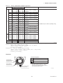
2.6.2 Withstand voltage test procedure
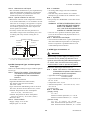
䊏 Testing between the output terminal and the
input terminal
1. Lay transition wiring between the + terminal, the –
terminal, and the check terminal of the terminal box.
2. Lay transition wiring between terminals 1, 2, 3, 4
and 5 of the terminal box.
3. Connect the withstand voltage tester (with the power
turned OFF) between the transition wiring shown in
Steps 1 and 2 above.
4. After setting the current limit value of the withstand
voltage tester to 10mA, turn the power ON, and
carefully increase the impressed voltage from 0V to
the specified value.
5. The voltage at the specified value must remain for a
duration of one minute.
6. Upon completion of the test, carefully reduce the
voltage so that no voltage surge occurs.
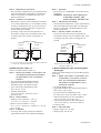
䊏 Testing between the output terminal and the
grounding terminal
1. Lay the transition wiring between the + terminal, the
- terminal and the check terminal of the terminal
box, and connect the withstand voltage tester (with
the power turned OFF) between the transition wiring
and the grounding terminal. Connect the grounding
side of the withstand voltage tester to the grounding
terminal.
2. After setting the current limit value of the withstand
voltage tester to 10mA, turn the power ON, and
gradually increase the impressed voltage from 0V to
the specified value.
3. The voltage at the specified value must remain for a
duration of one minute.
4. Upon completion of the test, carefully reduce the
voltage so that no voltage surge occurs.
䊏 Testing between the input terminal and the
grounding terminal
1. Lay the transition wiring across terminals 1, 2, 3, 4,
and 5 of the terminal box and connect the withstand
voltage tester (with the power turned OFF) between
the transition wiring and the grounding terminal.
Connect the grounding side of the withstand voltage
tester to the grounding terminal.
2. After setting the current limit value of the withstand
voltage tester to 10mA, turn the power ON, and
gradually increase the impressed voltage from 0V to
the specified value.
3. The voltage at the specified value must remain for a
duration of one minute.
4. Upon completion of the test, carefully reduce the
voltage so that no voltage surge occurs.
2.7 Installation of Explosion
Protected Type Transmitters
In this section, further requirements and differences
and for explosionproof type instrument are described.
For explosionproof type instrument, the description in
this chapter is prior to other description in this users
manual.
CAUTION
To preserve the safety of explosionproof equipment requires great care during mounting,
wiring, and piping. Safety requirements also
place restrictions on maintenance and repair
activities. Please read the following sections very
carefully.
2.7.1 CSA Certification
Model YTA110/CU1, YTA310/CU1 and YTA320/CU1
temperature transmitters can be selected the type of
protection (CSA Intrinsically Safe, Non-incendive, or
Explosionproof) for use in hazardous locations.
Note 1. For the installation of this transmitter,
once a particular type of protection is
selected, any other type of protection
cannot be used. The installation must be
in accordance with the description about
the type of protection in this instruction
manual.
Note 2. In order to avoid confusion, unnecessary
marking is crossed out on the label other
than the selected type of protection when
the transmitter is installed.
a) CSA Intrinsically Safe Type/Non-incendive
Type
Caution for CSA Intrinsically safe type. (Following
contents refers “DOC No. ICS008-A13 P.1-1 and P.12”)
Note 1. Model YTA110/CU1, YTA310/CU1 and
YTA320/CU1 temperature transmitters
are applicable for use in hazardous
locations:
Certificate 172608-0001053837
[For CSA C22.2]
• Applicable Standard: C22.2 No.0, C22.2 No.0.4,
C22.2 No.25, C22.2 No.94, C22.2 No.142, C22.2
No.157, C22.2 No.213
• Intrinsically Safe for Class I, II, III, Division 1,
Groups A, B, C, D, E, F & G.
• Non-incendive for Class I, II, Division 2, Groups A,
B, C, D, F & G, Class III, Division 1.
2-3
IM 01C50B01-01E










![j:j_"Xt$l"j:]:":,lg]:"r/Human Resources have been duty - e](http://vs1.manualzilla.com/store/data/005657435_1-26d97049bf04f0fd92265d73e45a9ab3-150x150.png)