1
User Manual
Compact Signal Calibrator
AMETEK JOFRA CSC101
Contents
1. Introduction. . . . . . . . . . . . . . . . . . . . . . . . . . . . . . . . . . . . . . . . . . . . . . . . . . . . . 1
1.1 Contacting Ametek. . . . . . . . . . . . . . . . . . . . . . . . . . . . . . . . . . . . . . . . . . . . . . . . . . . . . . . . . . 1
1.2 Standard Equipment. . . . . . . . . . . . . . . . . . . . . . . . . . . . . . . . . . . . . . . . . . . . . . . . . . . . . . . . . 1
1.3 Safety information. . . . . . . . . . . . . . . . . . . . . . . . . . . . . . . . . . . . . . . . . . . . . . . . . . . . . . . . . . . 2
2. Calibrator Interface. . . . . . . . . . . . . . . . . . . . . . . . . . . . . . . . . . . . . . . . . . . . . . . 4
2.1 Inputs and Primary User Interface. . . . . . . . . . . . . . . . . . . . . . . . . . . . . . . . . . . . . . . . . . . . . . 4
2.2 Calibrator Configuration. . . . . . . . . . . . . . . . . . . . . . . . . . . . . . . . . . . . . . . . . . . . . . . . . . . . . . 5
3. Operation in the Current Mode (4mA to 20mA) . . . . . . . . . . . . . . . . . . . . . . . 9
3.1 Sourcing Current. . . . . . . . . . . . . . . . . . . . . . . . . . . . . . . . . . . . . . . . . . . . . . . . . . . . . . . . . . . 9
3.2 Simulating Current. . . . . . . . . . . . . . . . . . . . . . . . . . . . . . . . . . . . . . . . . . . . . . . . . . . . . . . . . . 9
3.3 Measuring Current. . . . . . . . . . . . . . . . . . . . . . . . . . . . . . . . . . . . . . . . . . . . . . . . . . . . . . . . . 10
3.4 Measuring Current with Loop Power . . . . . . . . . . . . . . . . . . . . . . . . . . . . . . . . . . . . . . . . . . 10
4. Operation in the Voltage Mode. . . . . . . . . . . . . . . . . . . . . . . . . . . . . . . . . . . . 11
4.1 Measuring Volts (30VDC max). . . . . . . . . . . . . . . . . . . . . . . . . . . . . . . . . . . . . . . . . . . . . . . . 11
5. Advanced Features. . . . . . . . . . . . . . . . . . . . . . . . . . . . . . . . . . . . . . . . . . . . . . 12
5.1 Step and Ramp Operation. . . . . . . . . . . . . . . . . . . . . . . . . . . . . . . . . . . . . . . . . . . . . . . . . . . 12
5.2 Valve Test . . . . . . . . . . . . . . . . . . . . . . . . . . . . . . . . . . . . . . . . . . . . . . . . . . . . . . . . . . . . . . . . 12
5.3 Flow Calculation. . . . . . . . . . . . . . . . . . . . . . . . . . . . . . . . . . . . . . . . . . . . . . . . . . . . . . . . . . . 12
5.4 Hart 250Ω Resistor. . . . . . . . . . . . . . . . . . . . . . . . . . . . . . . . . . . . . . . . . . . . . . . . . . . . . . . . . 13
6. Specifications . . . . . . . . . . . . . . . . . . . . . . . . . . . . . . . . . . . . . . . . . . . . . . . . . 13
7. Maintenance . . . . . . . . . . . . . . . . . . . . . . . . . . . . . . . . . . . . . . . . . . . . . . . . . . . 14
7.1 Replacing Batteries . . . . . . . . . . . . . . . . . . . . . . . . . . . . . . . . . . . . . . . . . . . . . . . . . . . . . . . . 14
7.2 Cleaning the Unit . . . . . . . . . . . . . . . . . . . . . . . . . . . . . . . . . . . . . . . . . . . . . . . . . . . . . . . . . . 14
7.3 Service Center Calibration or Repair . . . . . . . . . . . . . . . . . . . . . . . . . . . . . . . . . . . . . . . . . . 14
7.4 Replacement Parts & Accessories. . . . . . . . . . . . . . . . . . . . . . . . . . . . . . . . . . . . . . . . . . . . . 14
2
1. Introduction
The Ametek Jofra CSC101 is a handheld Compact Signal Calibrator, primarily
designed to calibrate and verify 4 to 20mA process loops and precision
voltage signal conditioning equipment. The CSC101 can both source and
measure current over a 0 to 24mA range and measure voltage from zero to
30VDC. The calibrator has the following features and functions:
• A digital "knob" along with selectable decade control allows quick and easy
adjustment of the desired output.
• A large easy to read display used to display electrical parameters.
• Measurement and sourcing capabilities for current.
• Flow Calculation and Valve Test Capabilities.
• Voltage measurement capabilities.
• An interactive menu
• All input and output jacks are protected through internal self resetting fuses
providing protection to 240VAC.
1.1 Contacting Ametek
US, Canada, Latin America
AMETEK TCI at 1-800-527-9999
Europe, Africa, Middle East
AMETEK Denmark A/S at + 45 4816 8000
AsiaAMETEK Singapore Pte. Ltd. at
+ 65 (64) 842 388
1.2 Standard Equipment
Inspect the unit carefully upon receipt. Save packing carton in case
re-shipment is necessary. If there appears to be any damage, equipment
missing or if there are any questions about the unit, contact AMETEK.
Check to see if your calibrator is complete. It should include:
• CSC101 Calibrator
• Instruction Manual
• Test Leads
1
1.3 Safety information
Symbols Used
The following table lists the International Electrical Symbols. Some or all of
these symbols may be used on the instrument or in this manual.
SymbolDescription
AC (Alternating Current)
AC-DC
Battery
CE Complies with European Union Directives
DC
Double Insulated
Electric Shock
Fuse
PE Ground
Hot Surface (Burn Hazard)
Read the User’s Manual (Important Information)
Off
On
Canadian Standards Association
2
This calibrator must be recycled or disposed of properly (2002/96/EC).
The following definitions apply to the terms “Warning” and “Caution”.
• “Warning” identifies conditions and actions that may pose hazards to the
user.
• “Caution” identifies conditions and actions that may damage the
instrument being used.
Use the calibrator only as specified in this manual, otherwise injury and
damage to the calibrator may occur.
Warning
To avoid possible electric shock or personal injury:
• Do not apply more than the rated voltage. See specifications for
supported ranges.
• Follow all equipment safety procedures.
• Do not use the calibrator if it is damaged. Before you use the calibrator,
inspect the case. Look for cracks or missing plastic. Pay particular
attention to the insulation surrounding the connectors.
• Select the proper function and range for your measurement.
• Make sure the battery cover is closed and latched before you operate the
calibrator.
• Remove test leads from the calibrator before you open the battery door.
• Inspect the test leads for damaged insulation or exposed metal. Check
test leads continuity. Replace damaged test leads before you use the
calibrator.
• When using the probes, keep your fingers away from the probe contacts.
Keep your fingers behind the finger guards on the probes.
• Do not use the calibrator if it operates abnormally. Protection may be
impaired. When in doubt, have the calibrator serviced.
• Do not operate the calibrator around explosive gas, vapor, or dust.
• Disconnect test leads before changing to another measure or source
function.
• To avoid false readings, which could lead to possible electric shock or
personal injury, replace the battery as soon as the battery indicator
appears.
• To avoid personal injury or damage to the calibrator, use only the specified
replacement parts and do not allow water into the case.
3
Caution
To avoid possible damage to calibrator or to equipment under test:
• Disconnect the power and discharge all high-voltage capacitors before
testing resistance or continuity.
• Use the proper jacks, function, and range for your measurement or
sourcing application.
• To avoid damaging the plastic lens and case, do not use solvents or
abrasive cleansers.
Clean the calibrator with a soft cloth dampened with water or water and mild
soap.
2. Calibrator Interface
Mode
JOFRA
Simultaneous % Display
4mA = 0.00%
20mA = 100.00%
CSC101
Source
0.00%
4.000mA
Cursor
Compact Signal Calibrator
Step / Ramp Enable
Backlight
On / Off
MENU
EXIT
100%
100% Key: Sets Output to 20mA
25%
25% Key: Steps 4, 8, 12, 16, 20mA
0% Key: Sets Output to 4mA
0%
Digital Knob Sets Output Value
Press to Move Cursor
Menu
Press to Enter Setup Menu
Press Again to Exit
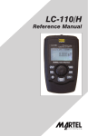
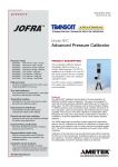
Figure 1
2.1 Inputs and Primary User Interface
The Calibrator has two numeric displays. The main display area displays
the signal which is being sourced or measured. The smaller numeric
display area is used in the mA modes to display the percent of range.
Normally values in the 4mA to 20mA range correspond to a percentage
from 0% to 100%. The unit can also be configured for 0 to 20 mA fullscale.
4
The CSC101 has one input terminal located on the top of the unit. These
terminals are provided for all milliamp functions and voltage functions. The
terminals will accommodate standard banana plugs.
The CSC101 has an knob and a series of key used to operate and
configure the unit.
Figure 1 shows the layout of the calibrator keypad while Table 1 lists the
calibrator's components and describes their functions.
2.2 Calibrator Configuration
2.2.1 Main Menu
The Main Menu is used to configure the primary mode of the calibrator and
allow access to the calibrator set-up.
mA Source
mA Simulate
mA Measure
mA Measure with 24V
Volts Measure
Calibrator Setup Menu
The knob is used to highlight the menu selection in reverse video. Pressing
the knob executes the highlighted action. If the user can exit without
making a change by pressing the Menu/Exit key.
2.2.2 Calibrator Setup Menus
The Calibrator Setup consists of two menu screens.
Auto Ramp Time
Auto Step Time
Flow Calculation
Valve Test
HART 250Ω Resistor
Other Parameters
mA Span
Contrast
Auto Shutdown Time
5
The knob is used to highlight the menu selection in reverse video. Pressing
the knob executes the highlighted action. The user can exit without making
a change by pressing the Menu/Exit key.
Setting Auto Ramp Time
Auto Ramp Time
10 SEC.
Press & hold to Save
This is the time for the mA ramp function (See Section 5 Advanced
Features). The value can be set from 5 to 300 seconds. The knob is used
to adjust the value. When the desired value is attained press and hold the
knob to save it. If you wish to revert to the previous value press the menu
exit key.
Setting Auto Step Time
Auto Step Time
10 SEC.
Press & hold to Save
This is the time for the mA Auto Step Feature (See Section 5 Advanced
Features). The value can be set from 5 to 300 seconds. The knob is used
to adjust the value. When the desired value is attained press and hold the
knob to save it. If you wish to revert to the previous value press the menu
exit key.
6
Enabling Valve Test
Valve Test Enable
OFF
ON
Use the knob to highlight the selection. Press the knob to store the
highlighted selection. If you wish to revert to the previous setting press the
menu exit key.
Enabling Flow Calculation
Valve Test Enable
OFF
ON
Use the knob to highlight the selection. Press the knob to store the
highlighted selection. If you wish to revert to the previous setting press the
menu exit key.
Enabling Hart Resistor
HART Resistor Enable
OFF
ON
Use the knob to highlight the selection. Press the knob to store the
highlighted selection. If you wish to revert to the previous setting press the
menu exit key.
7
Selecting mA Span
mA Span Selection
4 to 20 mA
0 to 20 mA
Use the knob to highlight the selection. Press the knob to store the
highlighted selection. If you wish to revert to the previous setting press the
menu exit key.
Contrast Adjustment
Contrast
Sample normal video
Sample reverse video
Use the knob to adjust the contrast. The range of values is shown by the
bar graph, with higher contrast shown by a longer bar. The sample normal
and reverse video text lines allow evaluation of both text modes. Press the
knob to store contrast value. If you wish to revert to the previous setting
press the menu exit key.
Configuring Auto Shutdown
Auto Shutdown Time
10 MIN.
8
Use the knob to adjust the time before the unit with shutdown if the user
interface is not used. Auto shutdown can also be disabled is disable by
turning the knob counter clockwise until “Disabled” is displayed on the
screen.
3. Operation in the Current Mode (4mA to 20mA)
The CSC101 offers four (4) different operational functions when operated in
the current or milliamp mode. These functions are:
1.mA Source - Current can be sourced from the CSC101 over a 0 to
24mA range into loads of up to 1000 ohms.
2.mA Simulate - The CSC101 can act like a 2-wire transmitter by
controlling the loop current when power comes from an external power
supply.
3.mA Measure - The CSC101 displays input current over a range of 0 to
24mA.
4.mA Measure with Loop Power - Displayed as mA Measure 24V, this
mode measures current while simultaneously supplying 24 volts to the
loop.
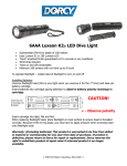
3.1 Sourcing Current
Figure 2 shows how to connect the CSC101 to source current.
(–)
4 to 20mA
4-20mA INPUT DEVICE
RECORDER/INDICATOR
SCADA SYSTEM ETC.
(+)
JOFRA
CSC101
Source
0.00%
4.000mA
Compact Signal Calibrator
100%
25%
MENU
EXIT
0%
Figure 2
3.2 Simulating Current
Figure 3 shows how to connect the CSC101 to simulate current (2-wire
mode) using an external power supply.
9
(+)
POWER SUPPLY
30 VDC MAX
4 to 20mA
(–)
JOFRA
(+)
CSC101
Simulate
0.00%
4-20mA
INPUT DEVICE
4.000mA
(–)
Compact Signal Calibrator
100%
25%
0%
MENU
EXIT
Figure 3
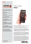
3.3 Measuring Current
Figure 4 shows how to connect the CSC101 to measure 4 to 20mA.
–
–
+
JOFRA
+
4 to 20mA
CSC101
Measure
0.00%
4.000mA
Compact Signal Calibrator
100%
25%
MENU
EXIT
0%
Figure 4
3.4 Measuring Current with Loop Power
Figure 5 shows the CSC101 connected to a 2-wire transmitter where the
CSC101 is providing 24 volt loop power while reading the resultant current.
10
–
4 to 20mA
+
JOFRA
CSC101
Measure 24V
0.00%
4.000mA
Compact Signal Calibrator
100%
25%
0%
MENU
EXIT
Figure 5
4. Operation in the Voltage Mode
The CSC101 can measure voltage up to 30 VDC.
4.1 Measuring Volts (30VDC max)
Figure 6 shows how to connect the CSC101 to measure volts.
)–(
Power Supply
or
Other Output Device
)+(
JOFRA
CSC101
Measure
10.000V
Compact Signal Calibrator
100%
25%
MENU
EXIT
0%
Figure 6
11
5. Advanced Features
The CSC101 has many advanced features that are available through the
Calibrator Setup Menus. How the features are enabled and what they do is
described below.
5.1 Step and Ramp Operation
The CSC101 has several unique features that are helpful aids when
doing milliamp calibrations. The percent keys allow the user to the output to
0% of scale, 100% of scale or in 25% steps from 0 or 4 to 20 mA. The "Step/
Ramp" allows hands free operation by automatically stepping or ramping
the milliamp output.
5.1.1 Manual Stepping
1. Use the main menu to set the CSC101 to source or simulate current.
2. Press the "25%" key to step the output in 25% increments from 4mA to
20mA and 20mA to 4mA.
5.1.2 Automatic Stepping & Ramping
1. Set the CSC101 to source or simulate current. See figures 2 & 3.
2. The CSC101 has separate Auto ramp and step times. Use the menu
system to set the step or ramp time. (see section 2.2 Calibrator
Configuration)
3. Once the desired times are set use the {ramp/step} to continually ramp
or step the value from 0% to 100% and back.
5.2 Valve Test
The has CSC101 has a Valve Test mode for verifying proper operation of
valves. In Valve Test user can step the output to the following values: 3.8
mA, 4.0mA, 4.2mA, 8.0 mA, 12.0 mA, 16.0 mA, 19.8 mA, 20.0 mA, 20.2 mA.
1. Use the main menu to set the CSC101 to source or simulate current.
2. If Valve Test is not enabled use the menu system to enable it. (see section
2.2 Calibrator Configuration)
3. The Press the Automatic Stepping Function or the "25%" key to step the
output to verify the proper valve operation.
5.3 Flow Calculation
The has CSC101 has a Flow Calculation mode for displaying flow (0-100%)
as a function of mA. Flow is displayed in the percent display. Flow
Calculation can be enabled through the menu system. (see section 2.2
Calibrator Configuration)
12
5.4 Hart 250Ω Resistor
The has CSC101 has the ability to insert a 250Ω resistor in series with the
power supply in order to facilitate the use or a Hart communicator. The Hart
resistor can be enabled through the menu system. (see section 2.2
Calibrator Configuration)
6. Specifications
Functions:
mA source, mA simulate, mA read, mA read/loop
power, and volts read.
Ranges:
mA (0 to 24mA) and Volts (0 to 30VDC)
Resolution:
1uA on mA ranges and 1mV on voltage range
Accuracy (1 year):
± 0.01% RDG +/- 2LSD, all ranges (@ 23° ±5°C)
Operating Temp range:
-10°C to 55°C
Humidity range:
10 to 95% non-condensing
Stability:
20ppm of F.S. /°C from -10°C to 18°C and 28°C to
55°C
Display:
128 x 64 pixels, LCD Graphic w/backlight, .34” high
digits
Power:
6AAA alkaline, lithium, or NiMH batteries
Battery Life:
≥ 40 hours continuous use (measure mode)
Loop Compliance Voltage: 24VDC @ 20mA
Loop Drive Capability:
1200Ω without HART resistor, 950 Ω with HART
resistor
Over-Voltage Protection:
240VAC
Overload Current
Protection:
28mA DC
EMC:
EN61326 Annex A (Portable Instruments)
Dimensions (L x W x D):
6” x 3.6” x 1.3” (15 cm x 9 cm x 3 cm)
Weight:
9.5 ounces (0.3 kg)
Included Accessories:
NIST traceable calibration certificate with data, batteries, test leads, and manual
13
7. Maintenance
7.1 Replacing Batteries
Replace batteries as soon as the battery indicator turns on to avoid false
measurements.
7.2 Cleaning the Unit
Warning
To avoid personal injury or damage to the calibrator, use only the specified
replacement parts and do not allow water into the case.
Caution
To avoid damaging the plastic lens and case, do not use solvents or
abrasive cleansers.
Clean the calibrator with a soft cloth dampened with water or water and mild
soap.
7.3 Service Center Calibration or Repair
Only qualified service personnel should perform calibration, repairs, or
servicing not covered in this manual. If the calibrator fails, check the
batteries first, and replace them if needed.
Verify that the calibrator is being operated as explained in this manual. If the
calibrator is faulty, send a description of the failure with the calibrator. Be
sure to pack the calibrator securely, using the original shipping container if it
is available.
7.4 Replacement Parts & Accessories
Order Number Description
14
SPK-CSC-004 Operating Manual
104203 Test Lead Set
SPK-CSC-004 Rev. B 10/12 0220063
15
AMETEK Calibration Instruments
is one of the world’s leading manufacturers
and developers of calibration instruments for
temperature, pressure and process signals as well
as for temperature sensors both from a commercial
and a technological point of view.
JOFRA Temperature Instruments
Portable precision thermometers. Dry-block and
liquid bath calibrators: 5 series, with more than 25
models and temperature ranges from -90° to 1205°C
/ -130° to 2200°F. All featuring speed, portability,
accuracy and advanced documenting functions with
JOFRACAL calibration software.
JOFRA Pressure Instruments
Convenient electronic systems ranging from -25
mbar to 1000 bar (0.4 to 15,000 psi) - multiple
choices of pressure ranges, pumps and accuracies,
fully temperature-compensated for problem-free and
accurate field use.
JOFRA Signal Instruments
Process signal measurement and simulation for
easy control loop calibration and measurement
tasks - from handheld field instruments to laboratory
reference level bench top instruments.
JOFRA / JF Marine Instruments
A complete range of calibration equipment for
temperature, pressure and signal, approved for
marine use.
FP Temperature Sensors
A complete range of temperature sensors for
industrial and marine use.
M&G Pressure Testers
Pneumatic floating-ball or hydraulic piston dead
weight testers with accuracies to 0.015% of reading.
M&G Pumps
Pressure generators from small pneumatic “bicycle”
style pumps to hydraulic pumps generating up to
1,000 bar (15,000 psi).
www.jofra.com
UK
Denmark
Singapore
France
USA
China
Germany
India
Lloyd Instruments Ltd
Tel +44 (0)1243 833 370
[email protected]
AMETEK S.A.S.
Tel +33 (0)1 30 68 89 40
[email protected]
AMETEK GmbH
Tel +49 (0)2159 9136 510
[email protected]
AMETEK Denmark
Tel +45 4816 8000
[email protected]
AMETEK MCT
Tel +1 (727) 536 7831
[email protected]
AMETEK Instruments India Pvt Ltd.
Tel +91 22 2836 4750
[email protected]
Information in this document is subject to change without notice. ©2012, by AMETEK, Inc., www.ametek.com. All rights reserved.
AMETEK Singapore Pte Ltd
Tel +65 6484 2388
[email protected]
AMETEK Inc. - Shanghai
Tel +86 21 5868 5111
AMETEK Inc. - Beijing
Tel +86 10 8526 2111
AMETEK Inc. - Guangzhou
Tel +86 20 8363 4768
[email protected]