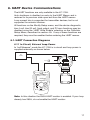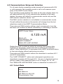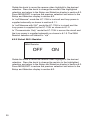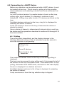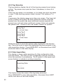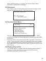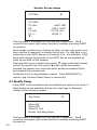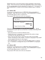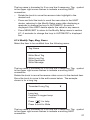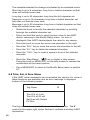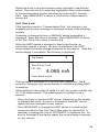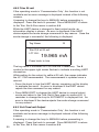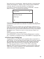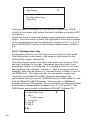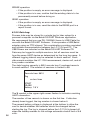
1
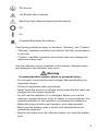
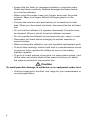
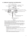
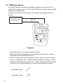
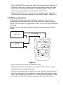
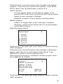
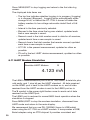
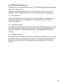
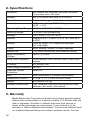
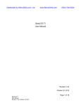
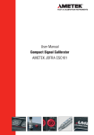
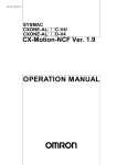
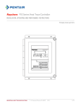
LC-110/H Reference Manual 1. Introduction . . . . . . . . . . . . . . . . . . . . . . . . . . . . . . . . . . . . . . . . 1 1.1 Customer Service . . . . . . . . . . . . . . . . . . . . . . . . . . . . . . . . . . . . . . . . . . . . . . . . . 1 1.2 Standard Equipment . . . . . . . . . . . . . . . . . . . . . . . . . . . . . . . . . . . . . . . . . . . . . . . 2 1.3 Safety information . . . . . . . . . . . . . . . . . . . . . . . . . . . . . . . . . . . . . . . . . . . . . . . . . 2 2. Calibrator Interface and Operation . . . . . . . . . . . . . . . . . . . . . 5 2.1 2.2 2.3 2.4 2.5 Milliamp Source. . . . . . . . . . . . . . . . . . . . . . . . . . . . . . . . . . . . . . . . . . . . . . . . . . Milliamp Simulate. . . . . . . . . . . . . . . . . . . . . . . . . . . . . . . . . . . . . . . . . . . . . . . . . . Milliamp Measure without 24V power. . . . . . . . . . . . . . . . . . . . . . . . . . . . . . . . . . Milliamp Measure with 24V power . . . . . . . . . . . . . . . . . . . . . . . . . . . . . . . . . . . . Volts Measure . . . . . . . . . . . . . . . . . . . . . . . . . . . . . . . . . . . . . . . . . . . . . . . . . . . . 6 7 8 9 9 3. Main Menu . . . . . . . . . . . . . . . . . . . . . . . . . . . . . . . . . . . . . . . . 10 4. Calibrator Setup Menu . . . . . . . . . . . . . . . . . . . . . . . . . . . . . . 11 4.1 4.2 4.3 4.4 4.5 4.6 4.7 4.8 Setting Auto Ramp Time . . . . . . . . . . . . . . . . . . . . . . . . . . . . . . . . . . . . . . . . . . . Setting Auto Step Time . . . . . . . . . . . . . . . . . . . . . . . . . . . . . . . . . . . . . . . . . . . . Enabling Valve Test . . . . . . . . . . . . . . . . . . . . . . . . . . . . . . . . . . . . . . . . . . . . . . . Enabling the HART Resistor. . . . . . . . . . . . . . . . . . . . . . . . . . . . . . . . . . . . . . . . . Selecting mA Span . . . . . . . . . . . . . . . . . . . . . . . . . . . . . . . . . . . . . . . . . . . . . . . Contrast Adjustment. . . . . . . . . . . . . . . . . . . . . . . . . . . . . . . . . . . . . . . . . . . . . . Configuring Auto Shutdown . . . . . . . . . . . . . . . . . . . . . . . . . . . . . . . . . . . . . . . . HART Write Enable. . . . . . . . . . . . . . . . . . . . . . . . . . . . . . . . . . . . . . . . . . . . . . . . 11 12 12 13 13 13 14 14 5. Advanced Features . . . . . . . . . . . . . . . . . . . . . . . . . . . . . . . . . 15 5.1 Step and Ramp Operation. . . . . . . . . . . . . . . . . . . . . . . . . . . . . . . . . . . . . . . . . . 15 5.2 Valve Test. . . . . . . . . . . . . . . . . . . . . . . . . . . . . . . . . . . . . . . . . . . . . . . . . . . . . . . 16 5.3 HART 250Ω Resistor . . . . . . . . . . . . . . . . . . . . . . . . . . . . . . . . . . . . . . . . . . . . . . 16 6. HART Device Communications . . . . . . . . . . . . . . . . . . . . . . . 17 6.1. HART Connection Diagrams. . . . . . . . . . . . . . . . . . . . . . . . . . . . . . . . . . . . . . . . 6.2 Communications Setup and Selection . . . . . . . . . . . . . . . . . . . . . . . . . . . . . . . . 6.3 Connecting to a HART Device. . . . . . . . . . . . . . . . . . . . . . . . . . . . . . . . . . . . . . . 6.4 Disconnect. . . . . . . . . . . . . . . . . . . . . . . . . . . . . . . . . . . . . . . . . . . . . . . . . . . . . . 6.5 Function Select Menu . . . . . . . . . . . . . . . . . . . . . . . . . . . . . . . . . . . . . . . . . . . . . 6.6 Display Setup & Data. . . . . . . . . . . . . . . . . . . . . . . . . . . . . . . . . . . . . . . . . . . . . . 6.7 Modify Setup . . . . . . . . . . . . . . . . . . . . . . . . . . . . . . . . . . . . . . . . . . . . . . . . . . . . 6.8 Trim, Set, & Zero Menu. . . . . . . . . . . . . . . . . . . . . . . . . . . . . . . . . . . . . . . . . . . . 6.9 Device Diagnostic. . . . . . . . . . . . . . . . . . . . . . . . . . . . . . . . . . . . . . . . . . . . . . . . 6.10 Data Log & Config Log. . . . . . . . . . . . . . . . . . . . . . . . . . . . . . . . . . . . . . . . . . . 6.11 HART Modem Simulation. . . . . . . . . . . . . . . . . . . . . . . . . . . . . . . . . . . . . . . . . . 6.12 Error Displays. . . . . . . . . . . . . . . . . . . . . . . . . . . . . . . . . . . . . . . . . . . . . . . . . . . 17 19 21 23 23 23 24 28 32 33 38 39 7. Maintenance . . . . . . . . . . . . . . . . . . . . . . . . . . . . . . . . . . . . . . 45 7.1 Replacing Batteries. . . . . . . . . . . . . . . . . . . . . . . . . . . . . . . . . . . . . . . . . . . . . . . 45 7.2 Cleaning the Unit. . . . . . . . . . . . . . . . . . . . . . . . . . . . . . . . . . . . . . . . . . . . . . . . . 45 7.3 Fuse Protection. . . . . . . . . . . . . . . . . . . . . . . . . . . . . . . . . . . . . . . . . . . . . . . . . . 45 8. Specifications . . . . . . . . . . . . . . . . . . . . . . . . . . . . . . . . . . . . . 46 9. Warranty . . . . . . . . . . . . . . . . . . . . . . . . . . . . . . . . . . . . . . . . . . 46 Introduction The Martel LC-110 and LC-110H are mA (loop) calibrators designed to be simple to use and to offer the highest accuracy of any loop calibrator in their class. The LC-110H differs from the standard LC-110 in that it incorporates HART communications and supports a select subset of the HART universal and common practice commands. This unique feature allows the LC-110H to be used as both a loop calibrator and basic function communicator. The calibrator supports the following functions: • Current measurement and sourcing, including selectable 24V supply • Voltage measurement • Valve test capability • Selectable HART 250Ω loop resistor • Output step and ramp The calibrator has the following features: • Large easy to read display for measurements and data entry • Digital knob with selectable decade control for quick and easy data entry • Interactive menus • Input and output jacks protected by self resetting fuses providing protection to 240VAC In the communicator mode the user is able to read basic device information, perform diagnostic tests, and trim the calibration on most HART enabled transmitters. In the past this could only be done with a dedicated communicator. The LC-110H can also be used as a HART modem, allowing PC host applications to perform more sophisticated diagnostics and setup. HART format commands from the host are passed to the transmitter, and responses are passed back. 1.1 Customer Service Corporate Office: www.martelcorp.com e-mail: [email protected] Tel: (603) 434-1433 800-821-0023 Fax: (603) 434-1653 Martel Electronics 3 Corporate Park Drive Derry, NH 03038 1 1.2 Standard Equipment Check to see if your calibrator is complete. It should include: • Calibrator • 6x AAA batteries (installed) • Test leads - The LC-110 is supplied with one set of leads with alligator clips installed - The LC-110H is supplied with two sets of tests. One set with alligator clips and the other set with mini-grabber style ends • Owner’s Manual • NIST Certificate 1.3 Safety information Symbols Used The following table lists the International Electrical Symbols. Some or all of these symbols may be used on the instrument or in this manual. Symbol Description AC (Alternating Current) AC-DC Battery CE Complies with European Union Directives DC Double Insulated Electric Shock Fuse 2 PE Ground Hot Surface (Burn Hazard) Read the User’s Manual (Important Information) Off On Canadian Standards Association The following definitions apply to the terms “Warning” and “Caution”. • “Warning” identifies conditions and actions that may pose hazards to the user. • “Caution” identifies conditions and actions that may damage the instrument being used. Use the calibrator only as specified in this manual, otherwise injury and damage to the calibrator may occur. Warning To avoid possible electric shock or personal injury: • Do not apply more than the rated voltage. See specifications for supported ranges. • Follow all equipment safety procedures. • Never touch the probe to a voltage source when the test leads are plugged into the current terminals. • Do not use the calibrator if it is damaged. Before you use the calibrator, inspect the case. Look for cracks or missing plastic. Pay particular attention to the insulation surrounding the connectors. • Select the proper function and range for your measurement. • Make sure the battery cover is closed and latched before you operate the calibrator. • Remove test leads from the calibrator before you open the battery door. 3 • Inspect the test leads for damaged insulation or exposed metal. Check test leads continuity. Replace damaged test leads before you use the calibrator. • When using the probes, keep your fingers away from the probe contacts. Keep your fingers behind the finger guards on the probes. • Connect the common test lead before you connect the live test lead. When you disconnect test leads, disconnect the live test lead first. • Do not use the calibrator if it operates abnormally. Protection may be impaired. When in doubt, have the calibrator serviced. • Do not operate the calibrator around explosive gas, vapor, or dust. • Disconnect test leads before changing to another measure or source function. • When servicing the calibrator, use only specified replacement parts. • To avoid false readings, which could lead to possible electric shock or personal injury, replace the battery as soon as the battery indicator appears. • To avoid a violent release of pressure in a pressurized system, shut off the valve and slowly bleed off the pressure before you attach the pressure module to the pressure line. Caution To avoid possible damage to calibrator or to equipment under test: • Use the proper jacks, function, and range for your measurement or sourcing application. 4 2. Calibrator Interface and Operation Mode LC-110H Simultaneous % Display 4mA = 0.00% 20mA = 100.00% Precision Loop Calibrator w/HART™ Source 0.00% 4.000mA Cursor MARTEL ELECTRONICS Step / Ramp Enable 100% 100% Key: Sets Output to 20mA Backlight 25% 25% Key: Steps 4, 8, 12, 16, 20mA On / Off MENU EXIT 0% Key: Sets Output to 4mA 0% Digital Knob Sets Output Value Press to Move Cursor Menu Press to Enter Setup Menu Press Again to Exit Figure 1 Figure 1 is typical of the main display for all operating modes. It shows the present measurement or output value. The individual operating modes are described below. Use the MENU/EXIT key to display the main menu described in section 3 to select the primary operating mode of the calibrator, to access the calibrator setup functions, or to enter HART mode. In output mode: • Press the knob to move the decade cursor. • Rotate the knob to increment or decrement the output in steps indicated by the selected decade. • Use the 3 percent keys to directly set the output to preset values. • Use the step/ramp key to select and stop these advanced modes which are described in section 5.1. 5 2.1 Milliamp Source In the mA Source mode the calibrator outputs a signal from 0 to 24mA into a load of up to 1000 ohms (750 ohms if the internal HART resistor is switched on). Figure 2 shows the main display and typical connections for this mode. 4-20mA INPUT DEVICE RECORDER/INDICATOR SCADA SYSTEM ETC. )+( 4 to 20mA )–( LC-110H Precision Loop Calibrator w/HART™ Source 0.00% 4.000mA MARTEL ELECTRONICS 100% 25% MENU EXIT 0% Figure 2 • Press the knob to move the decade cursor. • Rotate the knob to increment or decrement the output in steps indicated by the selected decade. • Use the 3 percent keys to directly set the output to preset values. • Use the step/ramp key to select and stop these advanced modes which are described in section 5.1. When automatic step or ramp is active one of the following is shown in the lower left corner: Automatic step: Automatic ramp: 6 ∧ • Press MENU/EXIT to enter the main menu described in section 3. • The text ‘Valve Test’ is shown in the lower center when the valve test function has been enabled on the Setup Menu, section 4.3. Valve test is described in more detail in section 5.2. • The text ‘250Ω’ text is shown in the lower right corner when the HART resistor has been enabled on the Setup Menu, section 4.4. 2.2 Milliamp Simulate In the mA Simulate mode the calibrator functions like a 2-wire transmitter by controlling the loop current from an external power supply. This function is a great way to test a loop with the transmitter removed. Figure 3 shows the main display and typical connections for this mode. )+( POWER SUPPLY 30 VDC MAX 4 to 20mA )–( LC-110H )+( Precision Loop Calibrator w/HART™ Simulate 4-20mA INPUT DEVICE 0.00% 4.000mA )–( MARTEL ELECTRONICS 100% 25% MENU EXIT 0% Figure 3 • Press the knob to move the decade cursor. • Rotate the knob to increment or decrement the output in steps indicated by the selected decade. • Use the 3 percent keys to directly set the output to preset values. • Use the step/ramp key to select and stop these advanced modes which are described in section 5.1. When automatic step or ramp is active one of the following is shown in the lower left corner: 7 Automatic step: Automatic ramp: ∧ • Press MENU/EXIT to enter the main menu described in section 3. • The text ‘Valve Test’ is shown in the lower center when the valve test function has been enabled on the Setup Menu, section 4.3. Valve test is described in more detail in section 5.2. • The text ‘250Ω’ text is shown in the lower right corner when the HART resistor has been enabled on the Setup Menu, section 4.4. 2.3 Milliamp Measure without 24V power In the mA Measure mode, the calibrator displays the loop current. Figure 4 shows the main display and typical connections for this mode. )+( 4-20mA OUTPUT DEVICE 4 to 20mA )–( LC-110H Precision Loop Calibrator w/HART™ Measure 0.00% 4.000mA MARTEL ELECTRONICS 100% 25% MENU EXIT 0% Figure 4 • Press MENU/EXIT to enter the main menu described in section 3. • The text ‘250Ω’ text is shown in the lower right corner when the HART resistor has been enabled on the Setup Menu, section 4.4. 8 2.4 Milliamp Measure with 24V power In the mA Measure with 24V mode, the calibrator outputs 24VDC while displaying the loop current. The mode is useful for powering a transmitter without the need for a separate power supply. Figure 5 shows the main display and typical connections for this mode. LC-110H Precision Loop Calibrator w/HART™ Measure 24V 0.00% 4.000mA MARTEL ELECTRONICS 100% 25% MENU EXIT 0% Figure 5 • Press MENU/EXIT to enter the main menu described in section 3. • The text ‘250Ω’ text is shown in the lower right corner when the HART resistor has been enabled on the Setup Menu, section 4.4. 2.5 Volts Measure In the Volts Measure mode, the calibrator displays the loop voltage. Figure 6 shows the main display and typical connections for this mode. • Press MENU/EXIT to enter the main menu described in section 3. 9 )+( VOLTAGE OUTPUT DEVICE )–( LC-110H Precision Loop Calibrator w/HART™ Measure 10.000V MARTEL ELECTRONICS 100% 25% MENU EXIT 0% Figure 6 3. Main Menu The Main Menu is used to select the primary operating mode of the calibrator, to access the calibrator setup functions, and to enter HART mode. mA Source mA Simulate mA Measure mA Measure with 24V Volts Measure Calibrator Setup Menu HART Comm. Menu Rotate the knob to select an action by moving the reverse video highlight up and down. Press the knob to perform the selected action. Press MENU/EXIT to return to the main display without performing an action. The first five actions change the operating mode accordingly and return to the main display described in section 2. The “Calibrator Setup Menu” action is described in section 4. The “HART Comm. Menu” action is described in section 6. The ‘HART’ menu item only appears on the LC-110H device. 10 4. Calibrator Setup Menu The calibrator setup menu consists of two screens. The second screen is reached by selecting ‘Other Parameters’ on the first screen. Auto Ramp Time Auto Step Time Valve Test HART 250Ω Resistor Other Parameters mA Span Contrast Auto Shutdown Time HART Write Enable Rotate the knob to select an action by moving the reverse video highlight up and down. Press the knob to perform the selected action. Press MENU/EXIT to return to the main display without performing an action. Note: The ‘HART Write Enable’ menu item only appears on the LC-110H device. 4.1 Setting Auto Ramp Time Auto Ramp Time 10 SEC. Press & hold to Save This function sets the full scale ramp time for the mA ramp feature described in more detail in section 5.1. The value can be set from 5 to 300 seconds. Rotate the knob to adjust the value. Press and hold the knob to save it. Press MENU/EXIT to restore the previous value and return to the main display. 11 4.2 Setting Auto Step Time Auto Step Time 10 SEC. Press & hold to Save This function sets the step interval time for the mA Auto Step feature described in more detail in section 5.1. The value can be set from 5 to 300 seconds. Rotate the knob to adjust the value. Press and hold the knob to save it. Press MENU/EXIT to restore the previous value and return to the main display. 4.3 Enabling Valve Test Valve Test Enable OFF ON This function enables and disables the valve test feature described in more detail in section 5.2. Rotate the knob to move the reverse video highlight to the desired selection. Press the knob to save the highlighted selection. Press MENU/EXIT to restore the previous selection and return to the main display. 12 4.4 Enabling the HART Resistor HART Resistor Enable OFF ON This function enables and disables the HART resistor described in more detail in section 5.3. Rotate the knob to move the reverse video highlight to the desired selection. Press the knob to save the highlighted selection. Press MENU/EXIT to restore the previous selection and return to the main display. 4.5 Selecting mA Span mA Span Selection 4 to 20 mA 0 to 20 mA This function selects the mA span used to calculate the percent of span field on the main display, and to set the value used by the 0% key. Rotate the knob to move the reverse video highlight to the desired selection. Press the knob to save the highlighted selection. Press MENU/EXIT to restore the previous selection and return to the main display. 4.6 Contrast Adjustment Contrast Sample normal video Sample reverse video This function sets the display contrast. Rotate the knob to adjust the contrast. The range of values is shown by the bar graph, with higher contrast shown by a longer bar. The sample normal and reverse video text lines allow evaluation of both 13 text modes. Press the knob to save the contrast value. Press MENU/ EXIT to restore the previous selection and return to the main display. 4.7 Configuring Auto Shutdown Auto Shutdown Time 10 MIN. This function sets or disables the time before the unit automatically shuts down if the keypad is not used. The value can be set to ‘Disabled’, or from 1 to 30 minutes. Rotate the knob to adjust the value. Press and hold the knob to save it. Press MENU/EXIT to restore the previous value and return to the main display. 4.8 HART Write Enable This setting is available only on the LC-110H. It protects all functions on the Modify Setup menu, and the Device Diagnostic, Trim 4mA, Trim 20mA, Set Fixed Output, and PV Zero functions. The default setting is “ON”, but may be turned off if the user wants to protect against unauthorized use. HART Write Enable OFF ON Rotate the knob to move the reverse video highlight to the desired selection. Press the knob to save the highlighted selection. Press MENU/EXIT to restore the previous selection and return to the main display. Before the setting is changed, a password is required to accept it. The password is set to 617 at the factory. Enter the password on the following display. The range of values that can be set is 000 to 999. 14 Password 000 Press & hold to Save Press the knob to move the decade cursor. Rotate the knob to adjust the value in steps indicated by the decade selected. Press and hold the knob to save the write enable setting. Press MENU/EXIT to restore the previous HART enable selection and return to the main display. The write enable setting is saved only when the correct password is entered. Otherwise an error message is displayed. 5. Advanced Features The calibrator has several advanced features that are available through the Calibrator Setup Menus. How the features are enabled and what they do is described below. 5.1 Step and Ramp Operation The calibrator has several unique features that are helpful aids when doing milliamp calibrations. The percent keys allow the user to set the milliamp output to 0% of span, 100% of span, or step it by 25% of span. The “Step/Ramp” key allows hands free operation by automatically stepping or ramping the milliamp output from 0% to 100% and back continuously. The 100% value is always 20 mA, but the 0% value may be 0 mA or 4 mA depending on the mA span setting described in section 4.5. The 25% step size is either 5 mA or 4 mA accordingly. 5.1.1 Manual Stepping 1. U se the main menu to set the calibrator to source or simulate current. 2. Press the “0%” key to set the output to 0% of span. 3. Press the “100%” key to set the output to 100% of span. 4. P ress the “25%” key to step the output in 25% of span increments, from 0% of span to 100% of span and back. 15 5.1.2 Automatic Stepping and Ramping 1. U se the main menu to set the calibrator to source or simulate current. 2. T he calibrator has separate Auto ramp and step times. Use the menu system to set the ramp or step time as described in section 4.1 or 4.2. 3. P ress the “Step/Ramp” key once to continually step the output from 0% of span to 100% of span and back in increments of 25% of span at the specified interval. Press the “Step/Ramp” once more to go to auto ramp. Press one of the percent keys, or the “Step/Ramp” twice more, to turn off the auto step and ramp. 4. P ress the “Step/Ramp” key twice to continually ramp the output from 0% of span to 100% of span over the specified interval, and then back over the specified interval. Press one of the percent keys, or the “Step/Ramp” once more, to turn off the auto step and ramp. 5.2 Valve Test The calibrator has a valve test mode for verifying proper operation of valves. In valve test the user can step the output to the following values: 3.8 mA, 4.0mA, 4.2mA, 8.0 mA, 12.0 mA, 16.0 mA, 19.8 mA, 20.0 mA, 20.2 mA, and back. The valve test mA values are not affected by the mA span setting described in section 4.5 1. U se the main menu to set the calibrator to source or simulate current. 2. If valve test is not enabled, use the menu system to enable it as described in section 4.3. 3. P ress the “Step/Ramp” key or the “25%” key to step the output to verify the proper valve operation. 4. Use the menu system to disable valve test when done. 5.3 HART 250Ω Resistor The calibrator has the ability to insert a 250Ω resistor in series with the power supply in order to facilitate the use of a HART communicator. The HART resistor is enabled through the menu system as described in section 4.4. 16 6. HART Device Communications The HART functions are only available in the LC-110H. Auto shutdown is disabled on entry to the HART Menus and is restored to its previous state upon exit from the HART menus. Loop current trim is supported for transmitter devices, but is not supported for actuator devices. All functions on the Modify Setup menu, and the device diagnostic, trim 4 mA, trim 20 mA, fixed output, and PV zero functions may be disabled using the ‘HART Write Enable’ selection on the Calibrator Setup Menu, described in section 4.8. If any of these functions are required, they must be enabled before entering the HART menus. 6.1. HART Connection Diagrams 6.1.1 In Circuit, External Loop Power In “mA Measure” mode the LC-110H is in circuit and loop power is supplied externally as shown below. )+( 24V SUPPLY )–( 4 to 20mA LC-110H Precision Loop Calibrator w/HART™ Measure 0.00% 4.000mA 250Ω MARTEL ELECTRONICS 100% 25% MENU EXIT 0% Note: In this situation the 250Ω HART resistor is enabled. If your loop already has 250Ω, do not enable the HART resistor. 17 6.1.2 In Circuit, LC-110H Loop Power In “mA Measure with 24V” mode the LC-110H is in circuit and the loop power is supplied by the LC-110H as shown below. )+( )–( LC-110H Precision Loop Calibrator w/HART™ Measure 24V 0.00% 4.000mA 250Ω MARTEL ELECTRONICS 100% 25% 0% MENU EXIT Note: In this situation the 250Ω HART resistor is enabled. If your loop already has 250Ω, do not enable the HART resistor. 6.1.3 Across Circuit, Communicator Only In “Communicator Only” mode the LC-110H is across the circuit and the loop power is supplied externally as shown below. )+( 24V SUPPLY 4 to 20mA RL≥250Ω )–( LC-110H Precision Loop Calibrator w/HART™ PT12234 Device Setup & Data Write LRV & URV Value Trim, Set, & Zero Device Diagnostic Data Log & Config Log MARTEL ELECTRONICS 100% 25% MENU EXIT 18 0% Note: In the Communicator Only Mode, there must be 250Ωs resistance present in the loop. 6.2 Communications Setup and Selection For all main display operating modes except mA measure with 24V or volts measure, the operating mode is set to mA measure upon entry of the HART Comm. Menu. The operating mode remains the same as the main display when it is mA measure with 24V. If volts measure was selected in the main display, the menu will default to communicator mode only and the 250Ω resistor selection shows “n/a”. The 250Ω resistor selection is not editable in communicator mode. On exit neither the mode nor the resistor will change from the last selections made in the HART Communications Menu. The mode and 250Ω resistor settings must correspond to how the test leads are hooked up before connecting or simulating a modem. HART Comm. Menu 4.123 mA Mode: mA 250Ω Resistor: ON HART CONNECT SIMULATE HART MODEM Rotate the knob to select an action by moving the reverse video highlight up and down. Press the knob to perform the selected action. Press MENU/EXIT to disconnect from HART mode and return to the main display without performing an action. The mode and 250Ω resistor actions are described in sections 6.2.1 and 6.2.2 respectively. The “HART CONNECT” action and subsequent operations are described in sections 6.3 through 6.10. An error is displayed and no action is taken if the measured input is out of range, OL, or –OL. The “SIMULATE HART MODEM” action is described in section 6.11. 6.2.1 Select Mode Mode mA Measure mA Measure with 24V Communicator Only 19 Rotate the knob to move the reverse video highlight to the desired selection. Press the knob to change the mode to the highlighted selection and return to the Setup and Selection display in section 6.2. Press MENU/EXIT to restore the previous selection and return to the Setup and Selection display in section 6.2. In “mA Measure” mode the LC-110H is in circuit and loop power is supplied externally as shown in section 6.1.1. In “mA Measure with 24V” mode the LC-110H is in circuit and the loop power is supplied by the LC-110H as shown in 6.1.2. In “Communicator Only” mode the LC-110H is across the circuit and the loop power is supplied externally as shown in 6.1.3. The 250Ω Resistor selection will default to “n/a”. 6.2.2 Select 250Ω Resistor 250Ω Resistor OFF ON Rotate the knob to move the reverse video highlight to the desired selection. Press the knob to change the resistor to the highlighted selection and return to the Setup and Selection display in section 6.2. Press MENU/EXIT to restore the previous selection and return to the Setup and Selection display in section 6.2. 20 6.3 Connecting to a HART Device Before any operation may be performed with a HART device, it must be located on the loop. This is done by polling all of the possible device addresses and selecting a device from those addresses that respond. If a HART protocol revision 5 or earlier device is found on the loop, polling stops at poll address 15, otherwise it continues to poll address 63. Polling stops after a total of 10 devices are found on the loop. If multiple devices are found on the loop, a tag list is displayed for selecting the device of interest. If only one device is found on the loop, it becomes the device of interest by default. Once a device of interest is determined all relevant data is read from the device and the operations described in sections 6.5 through 6.10 become available. 6.3.1 Polling The polling starts immediately and the display changes to the following where the string of dots is extended once per second to show the operation is progressing. Polling Loop ........... Found 2 devices Press knob to skip remainder The number of devices found on the loop so far during polling is displayed. The knob may be pressed to stop polling early if it is known that all of the devices on the loop have been found. Press MENU/EXIT to stop polling, disconnect from HART mode, and return to the main display. An error is displayed if no devices are found. If multiple devices are found, a list of tags is displayed for selecting the device of interest. If only one device is found the tag selection step is skipped. 21 6.3.2 Tag Selection The tag selection display lists all of the long tag names found during polling. Tag names may span two lines if necessary to show all of the text. If the long tag name is not available, or it is blank, the short tag name is used. If the short tag name is blank, the text “Poll address x” is used. If necessary, the display spans more than one screen. The lower left corner contains the symbol when additional screens follow the present one, the symbol when additional screens precede the present one, and both when additional screens follow and precede the present one. If there is only one screen, there is no symbol. Long Tag 1 on two lines Long Tag 2 Long Tag 3 Long Tag 4 on two lines Rotate the knob to move the reverse video highlight to the desired tag. Press the knob to select the highlighted tag and proceed to the data acquisition display. Press MENU/EXIT to disconnect from HART mode and return to the main display. 6.3.3 Data Acquisition This display is shown while acquiring all of the configuration data from the device. The string of dots is extended once per second to show the operation is progressing. The ♥ symbol in the upper right corner flashes to indicate a working connection. Acquiring Data ♥ ............ Tag name The display shows the name of the tag being accessed. Press MENU/EXIT to stop data acquisition, disconnect from HART mode, and return to the main display. 22 When data acquisition is complete, the Function Select Menu described in section 6.5 is displayed. 6.4 Disconnect This display is shown before returning to the main display to allow the user to disconnect the LC-110H from the loop. Disconnect from Loop Press Menu/Exit to exit HART mode 6.5 Function Select Menu Tag Name ♥ Display Setup & Data Modify Setup Trim, Set, & Zero Device Diagnostic Data Log & Config Log The tag name is truncated to fit on one line if necessary. The ♥ symbol in the upper right corner flashes to indicate a working HART connection. Rotate the knob to move the reverse video highlight to the desired action. Press the knob to select the highlighted action and proceed to the corresponding display described in sections 6.6 through 6.10. Press MENU/EXIT to disconnect from HART mode and return to the main display. 6.6 Display Setup & Data This display spans 11 screens with the following general format. It displays all of the data retrieved during the Data Acquisition procedure described in section 6.3.3. 23 Sample Screen Image PT12234 ♥ PT12234 PV Unit: inWC 68F PV: 226.0 inWC PV mA: 13.016 mA PV %: 56.35 % The tag name is truncated to fit on one line if necessary. The ♥ symbol in the upper right corner flashes to indicate a working HART connection. Each screen contains up to 6 items of data. An item may span more than one line if necessary to display the full text. If a data item is not supported in the HART device, it is marked “n/a”, not available. Data items that change dynamically in the HART device are updated as often as possible on the screens. The lower left corner contains the symbol when additional screens follow the present one, the symbol when additional screens precede the present one, and both when additional screens follow and precede the present one. Rotate the knob to step between screens. Press MENU/EXIT to return to the Function Select menu in section 6.5. 6.7 Modify Setup If the HART write commands are not enabled per section 4.8, none of these functions are available and an error message is displayed instead of the following screen. Tag Name ♥ Write LRV Write URV Write PV Unit Modify Tags,Msg,Descr 24 The tag name is truncated to fit on one line if necessary. The ♥ symbol in the upper right corner flashes to indicate a working HART connection. Rotate the knob to move the reverse video highlight to the desired action. Press the knob to select the highlighted action and proceed to the corresponding display described in section 6.7.1 through 6.7.4. Press MENU/EXIT to return to the Function Select menu in section 6.5. 6.7.1 Write LRV A warning to change the loop to MANUAL before proceeding is displayed. Press the knob to proceed. Press MENU/EXIT to return to the Modify Setup menu in section 6.7. The present LRV value and units are displayed.. Tag Name ♥ Write LRV: degrees F 300.5 Press & hold to Write The tag name is truncated to fit on one line if necessary. The ♥ symbol in the upper right corner flashes to indicate a working HART connection. • Press the knob to move the decade cursor. • Rotate the knob to increment or decrement the value in steps indicated by the selected decade. • Press and hold the knob to send the new value to the HART device, remaining on this display. An error is displayed if the HART device rejects the value for any reason. • Press MENU/EXIT to return to the Modify Setup menu in section 6.7. A reminder to change the loop to AUTOMATIC is displayed first. 6.7.2 Write URV A warning to change the loop to MANUAL before proceeding is displayed. Press the knob to proceed. Press MENU/EXIT to return to the Modify Setup menu in section 6.7. The present URV value and units are displayed. 25 Tag Name ♥ Write URV: degrees F 300.5 Press & hold to Write The tag name is truncated to fit on one line if necessary. The ♥ symbol in the upper right corner flashes to indicate a working HART connection. • Press the knob to move the decade cursor. • Rotate the knob to increment or decrement the value in steps indicated by the selected decade. • Press and hold the knob to send the new value to the HART device, remaining on this display. An error is displayed if the HART device rejects the value for any reason. • Press MENU/EXIT to return to the Modify Setup menu in section 6.7. A reminder to change the loop to AUTOMATIC is displayed first. 6.7.3 Write PV Unit A warning to change the loop to MANUAL before proceeding is displayed. Press the knob to proceed. Press MENU/EXIT to return to the Modify Setup menu in section 6.7. The available units are displayed with the present unit highlighted in reverse video. The available units listed correspond to the type of unit presently selected. For example, if the present unit is PSI only pressure units are listed, if the present unit is °C only temperature units are listed. Tag Name ♥ Select PV Unit: degree C degree F degree R degree K Press & hold to Write 26 The tag name is truncated to fit on one line if necessary. The ♥ symbol in the upper right corner flashes to indicate a working HART connection. • R otate the knob to move the reverse video highlight to the desired unit. • P ress and hold the knob to send the new value to the HART device, returning to the Modify Setup menu after displaying a reminder to change the loop to AUTOMATIC. An error is displayed if the HART device rejects the value for any reason. • P ress MENU/EXIT to return to the Modify Setup menu in section 6.7. A reminder to change the loop to AUTOMATIC is displayed first. 6.7.4 Modify Tags, Msg, Descr Select the item to be modified from the following menu. Tag Name ♥ Write Short Tag Write Long Tag Write Descriptor Write Message The tag name is truncated to fit on one line if necessary. The ♥ symbol in the upper right corner flashes to indicate a working HART connection. Rotate the knob to move the reverse video cursor to the desired item. Press the knob to move to the edit screen below. The example shown is for a long tag. Truncated Long Tag ♥ Long tag: Furnace 3 oxygen temp erature Press for help Press & hold to Write The tag name is truncated to fit on one line if necessary. The ♥ symbol in the upper right corner flashes to indicate a working HART connection. 27 The character selected for change is indicated by an underline cursor. Short tag is up to 8 characters long from a limited character set that does not include lower case. Long tag is up to 32 characters long from the full character set. Descriptor is up to 16 characters long from a limited character set that does not include lower case. Message is up to 32 characters long from a limited character set that does not include lower case. • R otate the knob to modify the selected character by scrolling through the available character set. • P ress and hold the knob to send the new value to the HART device, returning to the Modify Setup menu. An error is displayed if the HART device rejects the value for any reason. • Press the knob to move the cursor one character to the right. • Press the “25%” key to move the cursor one character to the left. • Press the “0%” key to delete the selected character. • P ress the “100%” key to insert a space in front of the selected character. key to display a help screen. • P ress the “Step/Ramp” Press the knob or MENU/EXIT on the help screen to resume the modification at the same position. • P ress MENU/EXIT to return to the Modify Setup menu in section 6.7. 6.8 Trim, Set, & Zero Menu If the HART write commands are not enabled per section 4.8, none of these functions are available and an error message is displayed instead of the following screen. Tag Name ♥ Trim D/A at 4 mA Trim D/A at 20 mA Set fixed mA Output PV Zero The tag name is truncated to fit on one line if necessary. The ♥ symbol in the upper right corner flashes to indicate a working HART connection. 28 Rotate the knob to move the reverse video highlight to the desired action. Press the knob to select the highlighted action and proceed to the corresponding display described in sections 6.8.1 through 6.8.4. Press MENU/EXIT to return to the Function Select menu in section 6.5. 6.8.1 Trim 4 mA If the operating mode is ‘Communicator Only’, this function is not available and an error message is displayed instead of the following screens. A warning to change the loop to MANUAL before proceeding is displayed. Press the knob to proceed. Press MENU/EXIT to return to the Trim, Set & Zero menu in section 6.8. While the HART device is changed to fixed output mode, an information display is shown. An error is displayed if the HART device rejects the mode change command for any reason. Once the mode change is successful, the following is displayed. Tag Name ♥ Trim D/A at 4 mA LC110H: 4.065 mA Press knob to trim The tag name is truncated to fit on one line if necessary. The ♥ symbol in the upper right corner flashes to indicate a working HART connection. While waiting for the output to settle at 4 mA, the screen indicates the LC-110H measurement. The measurement is updated once a second. • Press the knob to trim the HART device, remaining on this display to evaluate the result. An error is displayed if the HART device rejects the trim command for any reason. • Press MENU/EXIT to change the HART device to normal output mode and return to the Trim, Set & Zero menu in section 6.8. A reminder to change the loop to AUTOMATIC is displayed first. An error is displayed if the device rejects the mode change command for any reason. 29 6.8.2 Trim 20 mA If the operating mode is ‘Communicator Only’, this function is not available and an error message is displayed instead of the following screens. A warning to change the loop to MANUAL before proceeding is displayed. Press the knob to proceed. Press MENU/EXIT to return to the Trim, Set & Zero menu in section 6.8. While the HART device is changed to fixed output mode, an information display is shown. An error is displayed if the HART device rejects the mode change command for any reason. Once the mode change is successful, the following is displayed. Tag Name ♥ Trim D/A at 20 mA LC110H: 19.965 mA Press knob to trim The tag name is truncated to fit on one line if necessary. The ♥ symbol in the upper right corner flashes to indicate a working HART connection. While waiting for the output to settle at 20 mA, the screen indicates the LC-110H measurement. The measurement is updated once a second. • Press the knob to trim the HART device, remaining on this display to evaluate the result. An error is displayed if the HART device rejects the trim command for any reason. • Press MENU/EXIT to change the HART device to normal output mode and return to the Trim, Set & Zero menu in section 6.8. A reminder to change the loop to AUTOMATIC is displayed first. An error is displayed if the device rejects the mode change command for any reason. 6.8.3 Set Fixed mA Output If the operating mode is ‘Communicator Only’, this function is not available and an error message is displayed instead of the following screens. 30 A warning to change the loop to MANUAL before proceeding is displayed. Press the knob to proceed. Press MENU/EXIT to return to the Trim, Set & Zero menu in section 6.8. While the HART device is changed to fixed output mode, an information display is shown. An error is displayed if the HART device rejects the mode change command for any reason. Once the mode change is successful, the following is displayed. Tag Name ♥ LC110H: 4.065 mA Select fixed output: 4.000 mA Press & hold to Send The tag name is truncated to fit on one line if necessary. The ♥ symbol in the upper right corner flashes to indicate a working HART connection. The screen is used to set a fixed output and monitor the result with the LC-110H measurement. The measurement is updated once a second. The range of values that can be set is 3.0 to 21.0 mA. • Press the knob to move the decade cursor. • Rotate the knob to increment or decrement the value in steps indicated by the selected decade. • Press and hold the knob to send the new value to the HART device, remaining on this display. An error is displayed if the HART device rejects the value for any reason. • Press MENU/EXIT to change the HART device to normal output mode and return to the Trim, Set & Zero menu in section 6.8. A reminder to change the loop to AUTOMATIC is displayed first. An error is displayed if the device rejects the mode change command for any reason. 6.8.4 PV Zero A warning to change the loop to MANUAL before proceeding is displayed. Press the knob to proceed. Press MENU/EXIT to return to the Trim, Set & Zero menu in section 6.8. This screen requests the user to set the PV process input signal to zero and monitors the result with the LC-110H measurement. The measurement is updated once a second. 31 When the operating mode is ‘Communicator Only’, the mA measurement is not available and the message ‘mA not available’, ‘in Comm. Only mode’ is displayed instead. Tag Name ♥ Set PV input to zero LC110H: 4.065 mA Press knob to zero The tag name is truncated to fit on one line if necessary. The ♥ symbol in the upper right corner flashes to indicate a working HART connection. • Press the knob to zero the HART device, remaining on this display to evaluate the result. An error is displayed if the HART device rejects the zero command for any reason. • Press MENU/EXIT to return to the Trim, Set & Zero menu in section 6.8. A reminder to restore the PV process input signal to normal operating configuration and change the loop to AUTOMATIC is displayed first. 6.9 Device Diagnostic If the HART write commands are not enabled per section 4.8, this function is not available and an error message is displayed instead of the following screens. A warning to change the loop to MANUAL before proceeding is displayed. Press the knob to proceed. Press MENU/EXIT to return to the Function Select menu in section 6.5. Tag Name ♥ Self Test Press knob to test The tag name is truncated to fit on one line if necessary. The ♥ symbol in the upper right corner flashes to indicate a working HART connection. 32 Press the knob to start the test. While the self test is performed the bottom line changes to “Testing” and a string of dots is extended once per second to show the operation is progressing. At the end of the test the following screen is displayed. It shows either “No errors”, or the first error reported. Tag Name ♥ Self Test Results RAM fault The tag name is truncated to fit on one line if necessary. The ♥ symbol in the upper right corner flashes to indicate a working HART connection. The lower left corner contains the symbol when additional errors follow the present one, the symbol when additional errors precede the present one, and both when additional errors follow and precede the present one. If there is no error or only one error, there is no symbol. Rotate the knob to step between errors. Press MENU/EXIT to return to the Function Select menu in section 6.5. A reminder to change the loop to AUTOMATIC is displayed first. 6.10 Data Log & Config Log Configuration Log and Data Log are available when connected to a HART device. To use the Data Log and Config Log functions requires the purchase of the optional BetaLOG HART software application. BetaLOG HART allows the user to upload the data files from the LC-110H and store them on a PC as .TXT, .CSV or Excel files. BetaLOG HART includes the necessary communications cable and USB driver to support calibrator to PC communications. Additional cables can be purchased separately. 33 Tag Name ♥ Configuration Log Data Log The tag name is truncated to fit on one line if necessary. The ♥ symbol in the upper right corner flashes to indicate a working HART connection. Rotate the knob to move the reverse video highlight to the desired action. Press the knob to select the highlighted action and proceed to the corresponding display described in sections 6.10.1 or 6.10.2. Press MENU/EXIT to return to the Function Select menu in section 6.5. 6.10.1 Configuration Log Configuration data for up to 20 tags may be stored for later recall. The configuration data saved is the same as that shown on the Device Data screen, section 6.6. The initial display spans more than one screen and shows a list of the tags contained in storage. Tag names span two lines if they exceed the length of a single line. If a storage position is not used, the tag name area displays ‘<empty>’. After a storage position is selected, data may be saved to it, recalled from it, erased, or sent to the RS232 port. The data may also be uploaded to a personal computer via the BetaLOG HART Windows application. We recommend that you use PN: 1920049 (Lemo to USB Cable) for use with the BetaLOG HART Software . It incorporates a USB/Serial adapter using an FTDI chipset. This combination provides consistent and reliable communications between the LC-110H and PC. The USB Drivers are included on the BetaLOG HART Software CD. Configuration Log 8 Tag 1 on two lines 9 <empty> 10 Tag 3 11 Tag 4 34 ♥ The ♥ symbol in the upper right corner flashes to indicate a working HART connection. The lower left corner contains the symbol when additional screens follow the present one, the symbol when additional screens precede the present one, and both when additional screens follow and precede the present one. Rotate the knob to move the reverse video highlight to the desired storage position. Press the knob to select the storage position. Press MENU/EXIT to return to the Log Select menu in section 6.10. Once a storage position has been selected, the following menu is displayed to select the operation to be performed. Position: ♥ 3 Tag on two lines SAVE RECALL ERASE SEND The ♥ symbol in the upper right corner flashes to indicate a working HART connection. The number and contents of the storage position are shown at the top. The tag number is ‘<empty>’ if the storage position is empty. Rotate the knob to move the reverse video highlight to the desired operation. Press the knob to perform the operation. Press MENU/ EXIT to return to the Log Select menu in section 6.10. SAVE operation: • If the position is empty, save the present device configuration data into the storage position. • If the position is in use, confirm that the existing data is to be replaced with the present tag data before saving it into the storage position. RECALL operation: • If the position is empty, an error message is displayed. • If the position is in use, display the data in a sequence of screens identical to the Device Data screen, section 6.6. Return from those screens to this screen. 35 ERASE operation: • If the position is empty, an error message is displayed. • If the position is in use, confirm that the existing data is to be permanently erased before doing so. SEND operation: • If the position is empty, an error message is displayed. • If the position is in use, send the data to the RS232 port in a report format. 6.10.2 Data Log Process data may be stored for a single tag for later upload to a personal computer via the BetaLOG HART Windows application. We recommend that you use PN: 1920049 (Lemo to USB Cable) for use with the BetaLOG HART Software . It incorporates a USB/Serial adapter using an FTDI chipset. This combination provides consistent and reliable communications between the LC-110H and PC. The USB Drivers are included on the BetaLOG HART Software CD. Data may be logged in multiple sessions, but all sessions must be from the same HART device as determined by the long tag name. A different logging interval may be selected for each session. Each data sample contains the LC-110H measurement, device mA, and all four process variables. The data logging capacity is 9810 records less 2 overhead records for each session. The number of sessions is limited to 99. Records free: 9810 ♥ Tag on two lines START ERASE Battery: 7.6 V The ♥ symbol in the upper right corner flashes to indicate a working HART connection. The number of free records is shown on the first line. If data has already been logged, the tag number is shown below it. 36 The present battery voltage is displayed at the bottom to allow the user to decide whether the batteries should be changed before starting the log. The log is stopped before the LC-110H is turned off when the battery reaches its low voltage automatic shutoff limit of 5.6 volts. Rotate the knob to move the reverse video highlight to the desired operation. Press the knob to perform the operation. Press MENU/ EXIT to return to the Log Select menu in section 6.10. START operation: • If no free records remain, no free sessions remain, or the present HART device does not match the HART device already logged, an error message is displayed. • Otherwise, proceed to interval selection described below. ERASE operation: • If there is no logged data, an error message is displayed. • Otherwise, confirm that the existing data is to be permanently erased before doing so. Select the logging interval. Select Interval ♥ 1 second 2 seconds 5 seconds 10 seconds 30 seconds 60 seconds The ♥ symbol in the upper right corner flashes to indicate a working HART connection. Rotate the knob to move the reverse video highlight to the desired interval. Press the knob to start logging at that interval. Press MENU/EXIT to return to the first data log screen. While logging the following is displayed to monitor progress and to allow logging to be stopped. Logging ♥ Interval: 30 seconds Elapsed: 2:15:25 Records used: 270 Records free: 9430 LC110H 6.288 mA PV mA: 6.317 mA The ♥ symbol in the upper right corner flashes to indicate a working HART connection. 37 Press MENU/EXIT to stop logging and return to the first data log screen. The displayed data items are: • The top line indicates whether logging is in progress (Logging) or is stopped (Stopped). Logging stops automatically when storage is full, or before the LC-110H is turned off when the battery reaches its low voltage automatic shutoff limit of 5.6 volts. • Interval is the item previously selected. • Elapsed is the time since the log was started, updated each time a new sample is saved. • Records used is the total number used to date for all sessions, updated each time a new sample is saved. • Records free is the total number that remain unused, updated each time a new sample is saved. • LC110H is the present measurement, updated as often as possible. • PV mA is the last HART device measurement, updated as often as possible. 6.11 HART Modem Simulation Simulate HART Modem ♥ 4.123 mA The LEMO communications port is set to 1200 baud, 8 data bits plus odd parity, and 1 stop bit per the HART standard. All data received on the LEMO port is sent to the HART modem as is, and all data received from the HART modem is sent to the LEMO port as is. The ♥ symbol in the upper right flashes once for each set of data received on the LEMO port. The LEMO port is restored to normal 9600 baud operation when the simulation is stopped. Press MENU/EXIT to stop the modem simulation, disconnect from HART mode and return to the main display. We recommend that you use PN: 1920049 (Lemo to USB cable) when using the LC-110H as a HART modem. It incorporates a USB/ Serial adapter using an FTDI chipset. It provides consistent and 38 reliable communications between the LC-110H and PC. USB drivers are included on a CD with the cable when purchased from Martel. 6.12 Error Displays There are two classes of errors which may occur during HART communications. The first class contains errors that are reported by the loop device in its response. The second class contains errors that are detected by the LC110H when receiving responses from the loop device. Loop Device Errors These errors are reported by the loop device in its response to the LC110H, per the HART protocol. They are indicated by the text “Loop Device error:” at the top of the display. This is followed by one of the following error messages. 1) Invalid selection The data value sent with the HART command is not allowed by this loop device. The command was ignored by the loop device. HART response code 2. 2) Value too large The data value sent with the HART command is greater than the range allowed by this loop device. The command was ignored by the loop device. HART response code 3. 3) Value too small The data value sent with the HART command is less than the range allowed by this loop device. The command was ignored by the loop device. HART response code 4. 4) Message too short The HART command received contains fewer characters than expected by this loop device. The command was ignored by the loop device. HART response code 5. 5) Device specific error The loop device has detected a device specific error. The LC110H does not support the reporting of details on device specific errors. The command was ignored by the loop device. HART response code 6. 39 6) Write protected The loop device is write protected. The LC110H can not alter the write protect status of a device. The command was ignored by the loop device. HART response code 7. 7) Set to nearest possible value The data value sent with the HART command was rounded or truncated due to limitations within the loop device. The command was accepted by the loop device. The resultant data values should be checked. HART response code 8. 8) Update in progress The loop device is updating the data value on a delayed basis. The command was accepted by the loop device. HART response code 8. 9) Incorrect loop mA mode or value The loop device is not in fixed current mode, or the mA value supplied is invalid. The command was ignored by the loop device. HART response code 9. 10)LRV too high The LRV value received is greater than the Upper Transducer Limit of this loop device, or some other physical device limitation is exceeded. The command was ignored by the loop device. HART response code 9. 11)Applied process too high The data value received is greater than some device limit. The command was ignored by the loop device. HART response code 9. 12)LRV too low The LRV value received is less than the Lower Transducer Limit of this loop device, or some other device physical limitation is exceeded. The command was ignored by the loop device. HART response code 10. 13)Applied process too low The data value received is less than some device limit. The command was ignored by the loop device. HART response code 10. 40 14)URV too high The URV value received is greater than the Upper Transducer Limit of this loop device. The command was ignored by the loop device. HART response code 11. 15)Loop mA not active The loop device is in multi-drop mode. The command was ignored by the loop device. HART response code 11. 16)URV too low The URV value received is less than the Lower Transducer Limit of this loop device. The command was ignored by the loop device. HART response code 12. 17)LRV & URV out of limits The LRV and/or URV value received is outside of the Transducer Limits of this loop device, or some other device physical limitation is exceeded. The command was ignored by the loop device. HART response code 13. 18)Span too small The span of the LRV and URV values received is less than the Minimum Span allowed by this loop device. The command was ignored by the loop device. HART response code 14. 19)Access restricted The HART command received is not allowed when the loop device in its current operating mode. The command was ignored by the loop device. HART response code 16. 20)Invalid units code The units code received is not allowed by the loop device in its current operating mode. The command was ignored by the loop device. HART response code 18. 21)Invalid span The data values in the HART command would result in an invalid span for this loop device. The command was ignored by the loop device. HART response code 29. 41 22)Busy The loop device is temporarily busy performing some internal operation. The command was ignored by the loop device. Try the command again later. HART response code 32. 23)Command not implemented The HART command has not been implemented in this loop device. The command was ignored by the loop device. HART response code 64. 24)Character parity The loop device detected a character parity error in one or more characters received. The command was ignored by the loop device. Try the command again. If the error persists, check the power and connections to the loop device. HART response code 192 (hex C0). 25)Character over run The loop device detected a general communications error. The command was ignored by the loop device. Try the command again. If the error persists, check the power and connections to the loop device. HART response code 160 (hex A0). 26)Character framing The loop device detected a character framing error in one or more characters received. The command was ignored by the loop device. Try the command again. If the error persists, check the power and connections to the loop device. HART response code 144 (hex 90). 27)Check byte bad The command received by the loop device did not contain a valid check byte per the HART protocol definition. The command was ignored by the loop device. Try the command again. If the error persists, check the power and connections to the loop device. HART response code 136 (hex 88). 28)Buffer overflow The loop device detected a general communications error. The command was ignored by the loop device. Try the command again. If the error persists, check the power and connections to the loop device. HART response code 130 (hex 82). 42 LC110H Detected Errors These errors are detected by the LC110H when receiving responses from the loop device. They are indicated by the text “LC110H error:” at the top of the display. This is followed by one of the following error messages. a) No response The loop device did not respond to the last HART command sent. Check the power and connections to the loop device. Try the command again. b) Character parity The response received from the loop device contained one or more characters with an invalid parity check. Try the command again. If the error persists, check the power and connections to the loop device. c) Character frame The response received from the loop device contained one or more characters with an invalid frame format. Try the command again. If the error persists, check the power and connections to the loop device. 43 d) Character overrun A general communications error occurred during the response received from the loop device. Try the command again. If the error persists, check the power and connections to the loop device. e) Buffer overrun A general communications error occurred during the response received from the loop device. Try the command again. If the error persists, check the power and connections to the loop device. f) Framing bad The structure of the response received from the loop device did not match the HART protocol definition. Try the command again. If the error persists, check the power and connections to the loop device. g) Check byte bad The response received from the loop device did not contain a valid check byte per the HART protocol definition. Try the command again. If the error persists, check the power and connections to the loop device. h) Invalid address The response received from the loop device contained a HART device address different from that sent. Ensure there are no burst mode devices broadcasting on the loop. Try the command again. If the error persists, check the power and connections to the loop device. i) Invalid command The response received from the loop device contained a HART command code different from that sent. Try the command again. If the error persists, check the power and connections to the loop device. j) Invalid fixed data The structure of the response received from the loop device did not match the HART protocol definition. Try the command again. If the error persists, check the power and connections to the loop device. 44 7. Maintenance 7.1 Replacing Batteries Replace batteries as soon as the battery indicator turns on to avoid false measurement. If the batteries discharge too deeply the LC-110 will automatically shut down to avoid battery leakage. Note: Use only AAA size alkaline, lithium batteries, or rechargeable NiMh cells. 7.2 Cleaning the Unit Warning To avoid personal injury or damage to the calibrator, use only the specified replacement parts and do not allow water into the case. Caution To avoid damaging the plastic lens and case, do not use solvents or abrasive cleaners. Clean the calibrator with a soft cloth dampened with water or water and mild soap. 7.3 Fuse Protection The LC-110 Series is protected with an internal polyfuse against overcurrent conditions. The fuse will automatically reset, usually within a few seconds. Do not attempt to open the unit and troubleshoot. This will void the product warranty. 45 8. Specifications Functions: mA source, mA simulate, mA read, mA read/ loop power, and volts read. Ranges: mA (0 to 24mA) and Volts (0 to 30VDC) Resolution: 1uA on mA ranges and 1mV on voltage range Accuracy: 0.01% of reading ± 2LSD all ranges (@23° ± 5°C) Operating Temp Range: -10°C to 55°C (14°F to 131°F) Humidity Range: 10 to 95% non-condensing Storage: -20°C to 60°C (-4°F to 140°F) Stability: 20ppm of F.S. /°C from -10°C to 18°C and 28°C to 55°C Display: 128 x 64 pixels, LCD Graphic w/backlight, .34” high digits Power: 6AAA alkaline, lithium, or NiMH batteries Battery Life: ≥ 40 hours continuous use (measure mode) Loop Compliance Voltage: 24VDC @ 20mA Loop Drive Capability: 1200Ω without HART resistor, 950 Ω with HART resistor IP Rating: IEC 60529: IP40 Over-Voltage Protection: 240VAC Overload Current Protection: 28mA DC EMC: EN61326 Annex A (Portable Instruments) Dimensions (LxWxD): 6” x 3.6” x 1.3” (15 cm x 9 cm x 3 cm) Weight: 9.5 ounces (0.3 kg) Included Accessories: NIST traceable calibration certificate with data, batteries, test leads, and manual 9. Warranty Martel Electronics Corporation warrants all products against material defects and workmanship for a period of twelve (12) months after the date of shipment. Problems or defects that arise from misuse or abuse of the instrument are not covered. If any product is to be returned, a “Return Material Authorization” form can be obtained from our website www.martelcorp.com under customer service. You can 46 also call 1-800-821-0023 to have a form faxed. Martel will not be responsible for damage as a result of poor return packaging. Out of warranty repairs and recalibration will be subject to specific charges. Under no circumstances will Martel Electronics be liable for any device or circumstance beyond the value of the product. 47 www.martelcalibrators.com e-mail: [email protected] Tel: (603) 434-1433 800-821-0023 Fax: (603) 434-1653 Martel Electronics 3 Corporate Park Drive Derry, NH 03038 0220024 Rev B 8/13