1
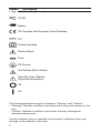
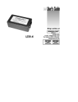
User’s Guide
Shop online at
omega.com
e-mail: [email protected]
For latest product manuals:
omegamanual.info
M-3666/0513
PCL1000 Multi-Function Calibrator
OMEGAnet ® Online Service
www.omega.com
Internet e-mail
[email protected]
Servicing North America:
USA:
ISO 9001 Certified
Canada:
One Omega Drive, Box 4047
Stamford CT 06907-0047
Tel: (203) 359-1660
e-mail: [email protected]
976 Bergar
Laval (Quebec) H7L 5A1, Canada
Tel: (514) 856-6928
e-mail: [email protected]
FAX: (203) 359-7700
FAX: (514) 856-6886
For immediate technical or application assistance:
USA and Canada: Sales Service: 1-800-826-6342 / 1-800-TC-OMEGA®
Customer Service: 1-800-622-2378 / 1-800-622-BEST®
Engineering Service: 1-800-872-9436 / 1-800-USA-WHEN®
TELEX: 996404 EASYLINK: 62968934 CABLE: OMEGA
Mexico:
En Españ ol: (001) 203-359-7803
FAX: (001) 203-359-7807
e-mail: [email protected]
[email protected]
Servicing Europe:
Benelux:
Postbus 8034, 1180 LA Amstelveen, The Netherlands
Tel: +31 (0)20 3472121
FAX: +31 (0)20 6434643
Toll Free in Benelux: 0800 0993344
e-mail: [email protected]
Czech Republic:
Frystatska 184, 733 01 Karvina´, Czech Republic
Tel: +420 (0)59 6311899
FAX: +420 (0)59 6311114
Toll Free: 0800-1-66342
e-mail: [email protected]
France:
11, rue Jacques Cartier, 78280 Guyancourt, France
Tel: +33 (0)1 61 37 2900
FAX: +33 (0)1 30 57 5427
Toll Free in France: 0800 466 342
e-mail: [email protected]
Germany/Austria: Daimlerstrasse 26, D-75392 Deckenpfronn, Germany
Tel: +49 (0)7056 9398-0
Toll Free in Germany: 0800 639 7678
e-mail: [email protected]
United Kingdom:
ISO 9002 Certified
FAX: +49 (0)7056 9398-29
One Omega Drive, River Bend Technology Centre
Northbank, Irlam, Manchester
M44 5BD United Kingdom
Tel: +44 (0)161 777 6611
FAX: +44 (0)161 777 6622
Toll Free in United Kingdom: 0800-488-488
e-mail: [email protected]
It is the policy of OMEGA to comply with all worldwide safety and EMC/EMI regulations that
apply. OMEGA is constantly pursuing certification of its products to the European New Approach
Directives. OMEGA will add the CE mark to every appropriate device upon certification.
The information contained in this document is believed to be correct, but OMEGA Engineering, Inc. accepts
no liability for any errors it contains, and reserves the right to alter specifications without notice.
WARNING: These products are not designed for use in, and should not be used for, human applications.
Table of Contents
1. Introduction
2. Quick Start Instructions
A. Key Functions . . . . . . . . . . . . . . . . . . . . . . . . . . . . . . . . . . . .4
B. Setpoints . . . . . . . . . . . . . . . . . . . . . . . . . . . . . . . . . . . . . . . .4
3. Connection Diagrams & Instructions
A. Measuring High Voltage AC or DC . . . . . . . . . . . . . . . . . . . .6
B. Measuring Low Voltage
and Frequency . . . . . . . . . . . . . . . . . . . . . . . . . . . . . . . . . . .6
C. Measuring Current . . . . . . . . . . . . . . . . . . . . . . . . . . . . . . . . .7
D. Sourcing Current . . . . . . . . . . . . . . . . . . . . . . . . . . . . . . . . . .7
E. Simulating Current . . . . . . . . . . . . . . . . . . . . . . . . . . . . . . . . .8
F. Sourcing Voltage/
Resistance/Frequency . . . . . . . . . . . . . . . . . . . . . . . . . . . . . .8
G. Sourcing a Thermocouple Signal . . . . . . . . . . . . . . . . . . . . .9
H. Measuring Temperature Using a Thermocouple . . . . . . . . .9
I. Measuring Resistance (RTDs) . . . . . . . . . . . . . . . . . . . . . . . .9
J. Sourcing Resistance (RTDs) . . . . . . . . . . . . . . . . . . . . . . . .10
4. Maintenance
A. Power Requirements . . . . . . . . . . . . . . . . . . . . . . . . . . . . . .11
B. Calibration . . . . . . . . . . . . . . . . . . . . . . . . . . . . . . . . . . . . . .11
5. Specifications . . . . . . . . . . . . . . . . . . . . . . . . . . . . . . . . . . . . .12
PCL1000
1. Introduction
The PCL1000 is designed to be a versatile, easy to use multi-function calibrator with a simple user interface. The following instructions will allow the
user to begin simple calibration tasks by learning the basic operation of the
keys and their functions.
1.1 Customer Service
Omega Engineering
One Omega Drive
Box 4047
Stamford, CT 06907-0047
Tel: (203) 359-1660
Fax: (203) 359-7811
www.omega.com
email: [email protected]
1.2 Unpacking
Remove the packing list and verify that all equipment has been received. If
there are any questions about the shipment please call Omega at 1-800826-6342. When the shipment is received inspect the container and
equipment for any signs of damage. Note any evidence of rough handling
in transit. Immediately report any damage to the shipping agent.
Note: The carrier will not honor any claims unless all shipping material is
saved for their examination. After examining and removing contents, save
packing material and carton in the event reshipment is necessary.
1.3 Safety information
Symbols Used
The following table lists the International Electrical Symbols. Some or all of
these symbols may be used on the instrument or in this manual.
1
Symbol
Description
AC (Alternating Current)
AC-DC
Battery
CE Complies with European Union Directives
DC
Double Insulated
Electric Shock
Fuse
PE Ground
Hot Surface (Burn Hazard)
Read the User’s Manual
(Important Information)
Off
On
The following definitions apply to the terms “Warning” and “Caution”.
• “Warning” identifies conditions and actions that may pose hazards to the
user.
• “Caution” identifies conditions and actions that may damage the
instrument being used.
Use the calibrator only as specified in this manual, otherwise injury and
damage to the calibrator may occur.
2
Warning
To avoid possible electric shock or
personal injury:
• Do not apply more than the rated voltage. See specifications for
supported ranges.
• Follow all equipment safety procedures.
• Do not use the calibrator if it is damaged. Before you use the calibrator,
inspect the case. Look for cracks or missing plastic. Pay particular
attention to the insulation surrounding the connectors.
• Select the proper function and range for your measurement.
• Make sure the battery cover is closed and latched before you operate the
calibrator.
• Remove test leads from the calibrator before you open the battery door.
• Inspect the test leads for damaged insulation or exposed metal.
• When using the probes, keep your fingers away from the probe contacts.
Keep your fingers behind the finger guards on the test leads.
• Do not use the calibrator if it operates abnormally. Protection may be
impaired. When in doubt, have the calibrator serviced.
• Do not operate the calibrator around explosive gas, vapor, or dust.
• Disconnect test leads before changing to another measure or source
function.
• When servicing the calibrator, use only specified replacement parts.
• To avoid false readings, which could lead to possible electric shock or
personal injury, replace the battery as soon as the battery indicator
appears.
Caution
To avoid possible damage to calibrator or to equipment under
test:
• Use the proper jacks, function, and range for your measurement or
sourcing application.
3
2. Quick Start Instructions
A. Key Functions
Function
Key
Input/Output
Toggles the function selected from measurement mode to
source mode.
V/mA/Hz
Selects between volts, milliamps, and frequency modes
TC/RTD
Selects between temperature modes either T/C or RTD.
Ohms and mV ranges are also included in these functions.
Ranges/Units This key toggles through all the ranges for a chosen function. Example: If T/C mode is selected the Range key toggles through the ranges J, K, T, E, etc.
0-9 keys
These keys allow a user to enter an output value. Example:
to output 20 mA select mA output and Press the “2” key
then the “0” key followed by the “ENTER” key.
Arrow ↑↓
These keys allow small changes to be made to an output
value. Press either the up or the down arrow key to set the
value as desired.
CE
The clear entry key allows the user to clear a value before
the enter key is pressed.
Shift
This key has a blue text color and acts as a second function key to all keys that have an associated second function. Features such as setpoints, °F/°C, backlight and
external pressure module activation all use the Shift key.
B. Setpoints
1. Storing Setpoints
The setpoint mode allows up to 9 setpoints to be stored in non-volitile memory for each range. The procedure is as follows:
a. Set the output to the desired value.
b. Press shift followed by the “SET” key.
c. Choose the desired setpoint storage location by pressing a key (1-9).
d. Enter a new value and repeat steps 1 thru 3 as needed, up to 9
setpoints for each range can be stored.
2. Recalling Setpoints
a. To recall a setpoint, press shift followed by the”SPT” key.
b. You will be prompted to enter the number of the desired setpoint
location stored previously.
c. Press the desired location number and the unit will go to that output.
4
3. Automated Stepping
The PCL1000 can auto-step through some or all of the stored setpoints for a given range. The procedure is as follows:
a. Press “Shift” followed by auto.
b. “Auto SPT ?” will appear. Enter the ending setpoint location.
Example: if you have all 9 setpoints stored but only want to step
through the first 3 then enter “3” for this question.
c. The next screen prompts you to enter the dwell time from 5 to 500
seconds. Simply enter a number in that range. Then press the
“Enter” key.
d. Auto-step will begin.
e. To exit auto-step press “CE” key or enter a value.
4. Manual Stepping
The PCL1000 can be manually stepped through all or some of the
stored setpoints. The procedure is as follows:
a. Press “Shift” followed by “Man”.
b. Using the arrow keys, toggle up and down through the stored setpoints.
c. To exit press CE or simply enter a new output value.
5. Pressure Module Interface
The PCL1000 has the capability to interface with a family of pressure
modules available from OMEGA. The procedure is as follows:
a. Connect the pressure module to the 15 pin “D” connector on top
of the PCL1000.
b. Press “Shift” followed by the “
” key.
c. Always zero the pressure module before starting a calibration.
Press “Shift” followed by the “Zero” key.
Note: More detailed information can be found with the instructions packaged
with each module.
5
3. Connection Diagrams & Instructions
A. Measuring High Voltage AC or DC
1. Select the Voltage Input Mode. Use the “Range” key to select either AC
or DC input.
2. Connect the device to be measured as shown in Figure 1.
! WARNING !
When measuring high voltage be sure to use proper connections as shown
in Figure 1. Failure to do so will cause serious damage to the calibrator.
Figure 1.
B. Measuring Low Voltage and Frequency
1. Select the desired mode Voltage or Frequency. Use the “Range” key to
select the proper range for the mode chosen.
2. Connect the device under test as shown in Figure 2.
6
Figure 2.
! WARNING !
Do not exceed 20 VDC at the V/Ω/Hz input.
C. Measuring Current
1. Select the mA input mode. Note: To power the loop while reading current, select the “mAPW” mode.
2. Connect the device under test as shown in Figure 3.
3. Current can either be measured directly in mA or as a percentage such
that 4 to 20 mA corresponds to 0 to 100%.
Figure 3.
D. Sourcing Current
1. Select the mA output mode on the calibrator.
2. Connect device under test as shown in Figure 4.
3. Enter the value of desired output current.
Note: If the loop is open “OL” will appear in the display.
Figure 4.
7
E. Simulating Current
The PCL1000 can act as a two-wire transmitter and control a 4-20mA loop
from the external power supply for that loop.
1. Select the mA “2W” output mode.
2. Connect the device as shown in figure 5.
3. Enter the desired output.
Figure 5.
F. Sourcing Voltage/Resistance/Frequency
1. Select the proper operation mode: volts, ohms, frequency.
2. Connect device under test as shown.
3. In the resistance or frequency modes use the “Range” key to choose the
desired range for the mode you’re operating in.
4. The PCL1000 is capable of driving up to ±1 mA on the Voltage and
Frequency ranges and is able to handle up to a 3 mA excitation on the
Resistance Simulation Range. Exceeding these limits will result in a warning on the display.
Figure 6.
Note: The frequency output is a 5 Volt square wave with –.1 volt offset
8
G. Sourcing a Thermocouple Signal
TC wire must be used to achieve an accurate calibration.
Figure 7.
Note: For best accuracy allow a 10 minute warm-up period after the
PCL1000 is turned on.
H. Measuring Temperature Using a Thermocouple
Figure 8.
I. Measuring Resistance (RTDs)
When measuring resistance (ohms) there are 3 choices when using the
PCL1000; 2-wire, 3-wire, and 4-wire. While 4-wire offers the highest accuracy, most industrial RTDs are a balance 3-wire. Figure 9. shows how to hook
up the PCL1000 for the 3 types of measurements.
1. Choose the desired RTD/ohms range by first pressing the “TC/RTD” key
to get into the RTD mode. Then use the “Range” key to select the desired
range within the RTD mode.
2. Make sure the PCL1000 is in the Input Mode (Note: that it will indicate 2,
3, or 4W in the upper left corner of the LCD).
To set the desired wire configuration use the “Up/Down arrow” keys to
toggle through the 2, 3, and 4 wire modes.
9
Measuring a 2 Wire RTD or Using the Continuity Function
Measuring a 3 Wire RTD
Measuring a 4 Wire RTD
Figure 9.
J. Sourcing Resistance Into a RTD Transmitter
1. As described previously in section F the PCL1000 can source resistance
in a RTD Transmitter or measuring device. In many cases the unit under
test will require a 3 or 4 wire connection to achieve best accuracy. Refer
to Figure 10 for connection information.
10
Figure 10.
4. Maintenance
A. Power Requirements
The PCL1000 operates on 4 AA alkaline batteries. To replace the alkaline batteries, remove the two (2) screws on the rear battery door and lift the battery
cover.
B. Calibration
The PCL1000 should hold its rated specifications for a minimum of one
year. Given this, annual re-calibration is required for best performance.
11
5. Specifications
Pressure
Ranges:
T/C Ranges:
RTD Ranges:
Ohms Ranges:
mA Range:
Voltage:
Frequency:
Continuity:
Accuracy:
mA Compliance:
Voltage Drive
Capability:
RTD IEX-range:
RTD Frequency
Response:
Oper. Temp:
Storage Temp:
Loop Power:
Size:
Module Dependent Operates with selected PX971
Transducers
J, K, T, E, R, S, N, B, L, U including – 10 to 70mV
Pt 385 (100, 200, 500, 1000 ohms)
Pt 392, JIS, Ni120, CU10, YSI400
0 to 400.00 and 400.0 to 4000.0
0 to 24.000 mA
(Low) Input 0-20.000 V, Output 0-10.000 V
(High) Input only 0-250 VDC or VAC
0-1000.0 CPM
Note: The frequency output is a 5
0-1000.0 Hz
Volt square wave with –.1 volt offset
0-10.00 KHz
0 to 400.0 ohms, audible tone when under 10 ohms
T/C Type J: ±.3°C ±10 mV (±0.6°C total error)
RTD PT100: ±.1°C ±.075 W (±0.3°C total error)
Ohms (400): ±0.1 W
Ohms (3200): ±1.0 W
Up to 1000 W load
1 mA
0.01 mA to 3 mA
10 mS – works with all pulsed XMTR’s
-10°C to 50°C
-40°C to 60°C
4 AA alkaline batteries, 25 hours typical operating time
7.5" x 4" x 1.5"
Range & Accuracy
Range
Min
Max
V Read (low)
VDC Read (high)
VAC Read (high)
V Source
mV Read
mV Source
mA Read
mA Source
0.000
0.0
0.0
0.000
0.00
0.00
0.000
0.000
CPM Source
Hz Source
1.0
1
600.0
1000
± 0.05%
± 0.05%
KHz Source
CPM Read
Hz Read
KHz Read
1.00
0.0
0
0.00
10.00
600.0
1000
10.00
± 0.25%
0.05% ± 1
0.05% ± 1
0.05% ± 1
12
20.000
250.0
250.0
10.000
90.00
100.00
24.000
24.000
Accuracy
(% of reading ± counts)
0.015% ± 2
0.05% ± 2
0.5% ± 2
0.015% ± 2
0.015% ±2
0.015% ±2
0.015% ± 2
0.015% ± 2
Range & Accuracy (cont.)
Range
Ohms Read (low)
Ohms Read (high)
Range
Ohms Source (low)
Ohms Source (high)
Min
0.00
400.0
1500.1
Min
5.00
5.00
400.0
1500.0
Max
400.00
1500.0
3200.0
Max
400.00
400.00
1500.0
3200.0
Thermocouple Read and Source (All errors included)
Range
Min
Max
J Thermocouple
-200.0
0.0
0.0
1200.0
K Thermocouple
-200.0
0.0
0.0
1370.0
T Thermocouple
-200.0
0.0
0.0
400.0
E Thermocouple
-200.0
0.0
0.0
950.0
R Thermocouple
-20
0.0
0
500
500
1750
S Thermocouple
-20
0
0
500
500
1750
B Thermocouple
600
800
800
1000
1000
1800
L Thermocouple
-200
0.0
0.0
900.0
U Thermocouple
-200
0.0
0.0
400.0
N Thermocouple
-200
0.0
0.0
1300.0
mV Read/Source
-10.00
75.00
RTD Read and Source
Range
Ni120 (672)
Pt100 (385)
Pt100(3926)
Pt100(3916)
Pt200(385)
Pt500(385)
Pt1000(385)
Cu10
YSI400
Min
-80.0
-200.0
-200.0
-200.0
-200.0
-200.0
500.0
-200.0
100.0
-100.0
15.00
Max
260.0
800.0
630.0
630.0
630.0
500.0
630.0
100.0
630.0
250.0
50.00
Accuracy
(% of reading ± counts)
0.1 ohm
0.5 ohm
1.0 ohm
Excitation
Current
0.1 to 0.5 mA
0.5 to 3 mA
0.05 to 0.8 mA
0.05 to 0.4 mA
Accuracy
0.15 ohm
0.1 ohm
0.5 ohm
1.0 ohm
Accuracy
0.6°C
0.4°C
0.8°C
0.5°C
0.8°C
0.5°C
0.5°C
0.4°C
2.49°C
1.7°C
1.3°C
2.4°C
1.7°C
1.4°C
2.1°C
1.7°C
1.3°C
0.45°C
0.4°C
0.7°C
0.45°C
1.1°C
0.6°C
0.015% ±.02 mV
Accuracy
0.2°C
0.33°C
0.3°C
0.3°C
0.8°C
0.3°C
0.4°C
0.2°C
0.3°C
2.2°C
0.05°C
13
14
WARRANT Y/ DISCLAIMER
OMEGA ENGINEERING, INC. warrants this unit to be free of defects in materials and
workmanship for a period of 13 months from date of purchase. OMEGA’s Warranty adds an
additional one (1) month grace period to the normal one (1) year product warranty to cover
handling and shipping time. This ensures that OMEGA’s customers receive maximum
coverage on each product.
If the unit malfunctions, it must be returned to the factory for evaluation. OMEGA’s Customer
Service Department will issue an Authorized Return (AR) number immediately upon phone or
written request. Upon examination by OMEGA, if the unit is found to be defective, it will be
repaired or replaced at no charge. OMEGA’s WARRANTY does not apply to defects resulting
from any action of the purchaser, including but not limited to mishandling, improper interfacing,
operation outside of design limits, improper repair, or unauthorized modification. This
WARRANTY is VOID if the unit shows evidence of having been tampered with or shows evidence
of having been damaged as a result of excessive corrosion; or current, heat, moisture or vibration; improper specification; misapplication; misuse or other operating conditions outside of
OMEGA’s control. Components which wear are not warranted, including but not limited to
contact points, fuses, and triacs.
OMEGA is pleased to offer suggestions on the use of its various products. However,
OMEGA neither assumes responsibility for any omissions or errors nor assumes liability for any damages that result from the use of its products in accordance with information provided by OMEGA,
either
verbal
or
written.
OMEGA
warrants
only
that
the
parts
manufactured by it will be as specified and free of defects. OMEGA MAKES NO OTHER
W A R R A N T I E S O R RE P R E S E N T A T I O N S O F A N Y K I N D W H A T S O E V E R , E X P R E S S O R I M P L I E D ,
EXCEPT THAT OF TITLE, AND ALL IMPLIED WARRANTIES INCLUDING ANY WARRANTY OF MERCHANTABILITY AND FITNESS FOR A PARTICULAR PURPOSE ARE HEREBY DISCLAIMED. LIMITATION OF LIABILITY: The remedies of purchaser set forth herein are exclusive, and the total liability of
OMEGA with respect to this order, whether based on contract, warranty, negligence, indemnification,
strict liability or otherwise, shall not exceed the purchase price of the component upon which liability
is based. In no event shall OMEGA be liable for consequential, incidental or special damages.
CONDITIONS: Equipment sold by OMEGA is not intended to be used, nor shall it be used: (1) as
a “Basic Component” under 10 CFR 21 (NRC), used in or with any nuclear installation or activity;
or (2) in medical applications or used on humans. Should any Product(s) be used in or with any
nuclear installation or activity, medical application, used on humans, or misused in any way,
OMEGA assumes no responsibility as set forth in our basic WARRANTY/ DISCLAIMER language,
and, additionally, purchaser will indemnify OMEGA and hold OMEGA harmless from any liability
or damage whatsoever arising out of the use of the Product(s) in such a manner.
RETURN REQUESTS/INQUIRIES
Direct all warranty and repair requests/inquiries to the OMEGA Customer Service Department.
BEFORE RETURNING ANY PRODUCT(S) TO OMEGA, PURCHASER MUST OBTAIN AN
AUTHORIZED RETURN (AR) NUMBER FROM OMEGA’S CUSTOMER SERVICE DEPARTMENT
(IN ORDER TO AVOID PROCESSING DELAYS). The assigned AR number should then be
marked on the outside of the return package and on any correspondence.
The purchaser is responsible for shipping charges, freight, insurance and proper packaging to
prevent breakage in transit.
FOR WARRANTY RETURNS, please have the
following information available BEFORE
contacting OMEGA:
1. Purchase Order number under which
the product was PURCHASED,
2. Model and serial number of the product
under warranty, and
3. Repair instructions and/or specific
problems relative to the product.
FOR NON-WARRANTY REPAIRS, consult
OMEGA for current repair charges. Have the
following information available BEFORE
contacting OMEGA:
1. Purchase Order number to cover the
COST of the repair,
2. Model and serial number of the
product, and
3. Repair instructions and/or specific problems
relative to the product.
OMEGA’s policy is to make running changes, not model changes, whenever an improvement is possible.
This affords our customers the latest in technology and engineering.
OMEGA is a registered trademark of OMEGA ENGINEERING, INC.
© Copyright 2004 OMEGA ENGINEERING, INC. All rights reserved. This document may not be copied, photocopied,
reproduced, translated, or reduced to any electronic medium or machine-readable form, in whole or in part, without
the prior written consent of OMEGA ENGINEERING, INC.
Where Do I Find Everything I Need for
Process Measurement and Control?
OMEGA…Of Course!
Shop online at www.omega.com
TEMPERATURE
✓ Thermocouple, RTD & Thermistor Probes, Connectors, Panels & Assemblies
✓ Wire: Thermocouple, RTD & Thermistor
✓ Calibrators & Ice Point References
✓ Recorders, Controllers & Process Monitors
✓ Infrared Pyrometers
PRESSURE, STRAIN AND FORCE
✓
✓
✓
✓
Transducers & Strain Gages
Load Cells & Pressure Gages
Displacement Transducers
Instrumentation & Accessories
FLOW/LEVEL
✓
✓
✓
✓
Rotameters, Gas Mass Flowmeters & Flow Computers
Air Velocity Indicators
Turbine/Paddlewheel Systems
Totalizers & Batch Controllers
pH/CONDUCTIVITY
✓
✓
✓
✓
pH Electrodes, Testers & Accessories
Benchtop/Laboratory Meters
Controllers, Calibrators, Simulators & Pumps
Industrial pH & Conductivity Equipment
DATA ACQUISITION
✓
✓
✓
✓
✓
Data Acquisition & Engineering Software
Communications-Based Acquisition Systems
Plug-in Cards for Apple, IBM & Compatibles
Datalogging Systems
Recorders, Printers & Plotters
HEATERS
✓
✓
✓
✓
✓
Heating Cable
Cartridge & Strip Heaters
Immersion & Band Heaters
Flexible Heaters
Laboratory Heaters
ENVIRONMENTAL
MONITORING AND CONTROL
✓
✓
✓
✓
✓
✓
Metering & Control Instrumentation
Refractometers
Pumps & Tubing
Air, Soil & Water Monitors
Industrial Water & Wastewater Treatment
pH, Conductivity & Dissolved Oxygen Instruments
M3666/0513