1
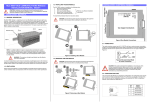
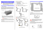
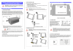
PROFI-2510 / PROFI-2541 User Manual Warranty All products manufactured by ICP DAS are warranted against defective materials for a period of one year from the date of delivery to the original purchaser. Warning ICP DAS assumes no liability for damages consequent to the use of this product. ICP DAS reserves the right to change this manual at any time without notice. The information furnished by ICP DAS is believed to be accurate and reliable. However, no responsibility is assumed by ICP DAS for its use, or for any infringements of patents or other rights of third parties resulting from its use. Copyright Copyright 2012 by ICP DAS Co., LTD. All rights reserved worldwide. Trademark The names used for identification only may be registered trademarks of their respective companies. Revision Note Date 2012/11/31 Author Version Ryan Lin 1.0 PROFI-2510 / PROFI-2541 User Manual Revision Release (Nov/2012) -------------1 Table of Content 1. Introduction ..............................................................................................................................3 1.1. Overview ....................................................................................................................3 1.2. Product Information ...............................................................................................3 1.3. Appearance ...............................................................................................................4 1.4. Features .....................................................................................................................4 1.5. Specifications...........................................................................................................5 2. Hardware ...................................................................................................................................6 2.1. Bus Wiring.................................................................................................................6 2.2. PROFIBUS Cable and Transmission Distance ................................................7 2.3. Status Indicator........................................................................................................8 2.4. Connector ..................................................................................................................9 2.5. Baud rate support .................................................................................................10 2.6. Wire Connection .................................................................................................... 11 Appendix A. Dimensions.............................................................................................................12 PROFI-2510 / PROFI-2541 User Manual (Nov/2012) -------------2 1. Introduction 1.1. Overview PROFIBUS is an open, digital communication system with a wide range of applications, particularly in the fields of factory automation and process automation. PROFIBUS is suitable for both fast, time-critical applications and complex communication tasks. PROFIBUS-DP is a famous protocol that enables simple, fast, cyclic and deterministic process data exchange between Master and assigned Slave. The PROFI-2510 is a PROFIBUS repeater used to establish a physical coupling of two or more segments of a CAN bus system. According to the PROFIBUS specification, up to 32 PROFIBUS devices are allowed per segment. Connecting via PROFI-2510, the division of a PROFIBUS system into several subsystems increases the maximum number of bus nodes. The PROFI-2541 is a PROFIBUS to Fiber Converter and it is the economic solution for applications which require protecting the data transmission from electrical exposure, surges, lightning or chemical corrosion. 1.2. Product Information Type Repeater Converter Model PROFI-2510 PROFI-2541 PROFI-2541-SC PROFI-2510 / PROFI-2541 User Manual Description Isolated PROFIBUS Repeater PROFIBUS to Fiber Converter(ST Type) PROFIBUS to Fiber Converter(SC Type) (Nov/2012) -------------3 1.3. Appearance PROFI-2510 1.4. Features PROFI-2510 Protocol Supports Transmission Rate (Kbps) Transmission Rate Setting Indicators PROFI-2541(SC) PROFIBUS DP 9.6, 19.2, 45.45, 93.75, 187.5, 500, 1500, 3000, 6000, 12000 detected automatically PWR LED, DP1 LED and DP2 LED ESD Protection Network Isolation Protection DC Isolation Protection 4kV class A High Speed iCoupler 3000VDC on PROFIBUS side PROFI-2541/ PROFI-2541-SC Protocol Supports Transmission Rate (Kbps) PROFIBUS DP 9.6, 19.2, 45.45, 93.75, 187.5, 500, 1500, 3000 PROFI-2510 / PROFI-2541 User Manual (Nov/2012) -------------4 Transmission Rate Setting Indicators Fiber Wave Length Fiber Type Network Isolation Protection DC Isolation Protection 1.5. Specifications PROFI-2510 PROFIBUS Interface PROFIBUS Transceiver Transmission Rate Power Requirement Power Consumption Operating Temp. Storage Temp. Humidity Dimensions detected automatically PWR LED, TxD LED and RxD LED 850 nm ST / SC(Multi-Mode) High Speed iCoupler 3000VDC on PROFIBUS side 9-pin D-Sub(Female) ADI ADM2486 iCoupler Isolated transceiver Up to 12Mbps 10V ~ 30V 1W -25℃ ~ +75℃ -30℃ ~ +85℃ 5% ~ 95%(Non Condensing) 33 mm x 126.8 mm x 93.4 mm (W x L x H) PROFI-2541/ PROFI-2541-SC PROFIBUS Interface 9-pin D-Sub(Female) PROFIBUS Transceiver ADI ADM2486 iCoupler Isolated transceiver Transmission Rate Up to 3Mbps Power Requirement 10V ~ 30V Connector ST / SC(Multi-Mode) Wave Length 850 nm Fiber cable 62.5 / 125 μm Propagation Delay Transmission Distance Operating Temp. Storage Temp. Humidity Dimensions PROFI-2510 / PROFI-2541 User Manual 125ns max (125ns delay shortens bus line length by ~ 25 m) 1.4 km max (in 62.5/125 μm fiber cable) -25℃ ~ +75℃ -30℃ ~ +85℃ 5% ~ 95%(Non Condensing) 33 mm x 126.8 mm x 104.5 mm (W x L x H) (Nov/2012) -------------5 2. Hardware 2.1. Bus Wiring In order to minimize the reflection effect of the signal transmission, PROFIBUS device has to fit with an active terminal resistor at both first node and last node, as shown below However, the number of station in PROFIBUS network is also restricted. According to PROFIBUS specification, it is up to 32 stations connected in a PROFIBUS segment. If more than 32 stations are connected, the PROFIBUS repeater must be used to link the individual bus segments. PROFI-2510 / PROFI-2541 User Manual (Nov/2012) -------------6 2.2. PROFIBUS Cable and Transmission Distance The PROFIBUS cable with following properties has different transmission distance with respect to different transmission rate, shown in the following table 1. 2. 3. 4. 5. Impedance :135~165Ω Capacity : lower than 30 pF/m Loop resistance : lower than 110Ω/Km Wire diameter : larger than 0.65mm Core cross-section : larger than 0.34mm2 Transmission Rate(Kbps) 9.6, 19.2, 45.45, 93.75 187.5 500 1500 3000, 6000, 12000 PROFI-2510 / PROFI-2541 User Manual Transmission Distance per Segment (meter) 1200 1000 400 200 100 (Nov/2012) -------------7 2.3. Status Indicator PROFI-2510 PROFI-2541(SC) It provides three status indicator, In PROFI-2510, they are PWR LED (red),DP1 LED(green) and DP2 LED (green). In PROFI-2541(SC), they are PWR LED (red), TxD LED(green) and RxD LED (green). When the power is supplied to module, PWR LED will turn on; Transmitting/receiving one data to/from fiber cable will flash the DP1/DP2/TxD/RxD LED once. The DP1/DP2/TxD/RxD LED may always be turned on if there are a lot of datas transmitted on fiber cable. PROFI-2510 PROFI-2541(SC) PWR Led (Red) PWR Led (Red) ON Module active ON Module active OFF Module inactive OFF Module inactive DP1 Led (Green) TxD Led (Green) Flashing Data transmitting Flashing Data transmitting OFF OFF No data transmitting No data transmitting DP2 Led (Green) RxD Led (Green) Flashing Data transmitting Flashing Data transmitting OFF OFF No data transmitting PROFI-2510 / PROFI-2541 User Manual No data transmitting (Nov/2012) -------------8 2.4. Connector The connector of PROFI-2510 / PROFI-2541(SC) is shown below Pin No. Signal Meaning 3 B-Line Receive/Transmit data - plus 4 CNTR-P Repeater control signal, RTS signal 5 GND Power ground of active terminator 6 VP Power 5 volt of active terminator 8 A-Line Receive/Transmit data - minus Note: The connector of PROFI-2510 / PROFI-2541(SC) has no terminators; users must use the connector with the terminator inside. The power of the terminator will provide by terminal device. PROFI-2510 / PROFI-2541 User Manual (Nov/2012) -------------9 2.5. Baud rate support PROFI-2510 / PROFI-2541(SC) has a functionality of auto- detection for baud rates, users don’t need to set the baud rate manually. PROFI-2510 supports the entire baud rates of PROFIBUS. They are 9.6Kbps, 19.2Kbps, 45.45Kbps, 187.5Kbps, 500Kbps, 1.5Mbps, 3Mbps, 6Mbps, and 12Mbps. PROFI-2541(SC) supports the entire baud rates of PROFIBUS. They are 9.6Kbps, 19.2Kbps, 45.45Kbps, 187.5Kbps, 500Kbps, 1.5Mbps, and 3Mbps. Note: Many baud rates only are supported by the particular cable or speed. For the detail, please refer to the above section “PROFIBUS Cable and Transmission Distance” PROFI-2510 / PROFI-2541 User Manual (Nov/2012) -------------10 2.6. Wire Connection PROFI-2510 If PROFI-2510 is a end device of PROFIBUS segment 1 and PROFIBUS segment 2. The terminal resistor of segment 1 is ON. The terminal resistor of segment 2 is ON. If PROFI-2510 is an intermediary device of PROFIBUS segment 1. The terminal resistor of segment 1 is OFF. PROFI-2541(SC) PROFI-2510 / PROFI-2541 User Manual (Nov/2012) -------------11 Appendix A. Dimensions PROFI-2510 PROFI-2510 / PROFI-2541 User Manual (Nov/2012) -------------12 PROFI-2541 PROFI-2510 / PROFI-2541 User Manual (Nov/2012) -------------13 PROFI-2541-SC PROFI-2510 / PROFI-2541 User Manual (Nov/2012) -------------14