1
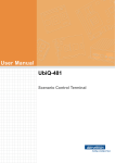
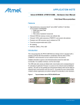
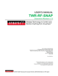
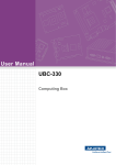
User Manual UbiQ-231 Scenario Control Terminal Copyright The documentation and the software included with this product are copyrighted 2012 by Advantech Co., Ltd. All rights are reserved. Advantech Co., Ltd. reserves the right to make improvements in the products described in this manual at any time without notice. No part of this manual may be reproduced, copied, translated or transmitted in any form or by any means without the prior written permission of Advantech Co., Ltd. Information provided in this manual is intended to be accurate and reliable. However, Advantech Co., Ltd. assumes no responsibility for its use, nor for any infringements of the rights of third parties, which may result from its use. Acknowledgements ARM is trademarks of ARM Corporation. Ti OMAP is trademarks of Ti Corporation. Microsoft Windows are registered trademarks of Microsoft Corp. All other product names or trademarks are properties of their respective owners. Declaration of Conformity CE This product has passed the CE test for environmental specifications. Test conditions for passing included the equipment being operated within an industrial enclosure. In order to protect the product from being damaged by ESD (Electrostatic Discharge) and EMI leakage, we strongly recommend the use of CE-compliant industrial enclosure products. FCC Class B Note: This equipment has been tested and found to comply with the limits for a Class B digital device, pursuant to part 15 of the FCC Rules. These limits are designed to provide reasonable protection against harmful interference in a residential installation. This equipment generates, uses and can radiate radio frequency energy and, if not installed and used in accordance with the instructions, may cause harmful interference to radio communications. However, there is no guarantee that interference will not occur in a particular installation. If this equipment does cause harmful interference to radio or television reception, which can be determined by turning the equipment off and on, the user is encouraged to try to correct the interference by one or more of the following measures: Reorient or relocate the receiving antenna. Increase the separation between the equipment and receiver. Connect the equipment into an outlet on a circuit different from that to which the receiver is connected. Consult the dealer or an experienced radio/TV technician for help.\ UbiQ-231 User Manual Part No. 2008023100 Edition 1 Printed in Taiwan March 2012 ii Warning! Any changes or modifications made to the equipment which are not expressly approved by the relevant standards authority could void your authority to operate the equipment. Technical Support and Assistance 1. 2. Visit the Advantech website at http://support.advantech.com where you can find the latest information about the product. Contact your distributor, sales representative, or Advantech's customer service center for technical support if you need additional assistance. Please have the following information ready before you call: – Product name and serial number – Description of your peripheral attachments – Description of your software (operating system, version, application software, etc.) – A complete description of the problem – The exact wording of any error messages Warnings, Cautions and Notes Warning! Warnings indicate conditions, which if not observed, can cause personal injury! Caution! Cautions are included to help you avoid damaging hardware or losing data. e.g. There is a danger of a new battery exploding if it is incorrectly installed. Do not attempt to recharge, force open, or heat the battery. Replace the battery only with the same or equivalent type recommended by the manufacturer. Discard used batteries according to the manufacturer's instructions. Note! Notes provide optional additional information. iii UbiQ-231 User Manual Safety Instructions 1. 2. 3. Read these safety instructions carefully. Keep this User Manual for later reference. Disconnect this equipment from any AC outlet before cleaning. Use a damp cloth. Do not use liquid or spray detergents for cleaning. 4. For plug-in equipment, the power outlet socket must be located near the equipment and must be easily accessible. 5. Keep this equipment away from humidity. 6. Put this equipment on a reliable surface during installation. Dropping it or letting it fall may cause damage. 7. The openings on the enclosure are for air convection. Protect the equipment from overheating. DO NOT COVER THE OPENINGS. 8. Make sure the voltage of the power source is correct before connecting the equipment to the power outlet. 9. Position the power cord so that people cannot step on it. Do not place anything over the power cord. 10. All cautions and warnings on the equipment should be noted. 11. If the equipment is not used for a long time, disconnect it from the power source to avoid damage by transient overvoltage. 12. Never pour any liquid into an opening. This may cause fire or electrical shock. 13. Never open the equipment. For safety reasons, the equipment should be opened only by qualified service personnel. 14. If one of the following situations arises, get the equipment checked by service personnel: The power cord or plug is damaged. Liquid has penetrated into the equipment. The equipment has been exposed to moisture. The equipment does not work well, or you cannot get it to work according to the user's manual. The equipment has been dropped and damaged. The equipment has obvious signs of breakage. 15. DO NOT LEAVE THIS EQUIPMENT IN AN ENVIRONMENT WHERE THE STORAGE TEMPERATURE MAY GO BELOW -20° C (-4° F) OR ABOVE 60° C (140° F). THIS COULD DAMAGE THE EQUIPMENT. THE EQUIPMENT SHOULD BE IN A CONTROLLED ENVIRONMENT. 16. CAUTION: DANGER OF EXPLOSION IF BATTERY IS INCORRECTLY REPLACED. REPLACE ONLY WITH THE SAME OR EQUIVALENT TYPE RECOMMENDED BY THE MANUFACTURER, DISCARD USED BATTERIES ACCORDING TO THE MANUFACTURER'S INSTRUCTIONS. The sound pressure level at the operator's position according to IEC 704-1:1982 is no more than 70 dB (A). DISCLAIMER: This set of instructions is given according to IEC 704-1. Advantech disclaims all responsibility for the accuracy of any statements contained herein. Instructions for the User The document combines text and illustrations, providing a comprehensive overview of the system. The information is presented as sequential steps of action, allowing the user to learn directly how to use the device. The text provides explanations and instructs the user step by step in the practical use of the product, with short, clear instructions in easy-to-follow sequence. UbiQ-231 User Manual iv Contents Chapter 1 Introduction..........................................1 1.1 Overview ................................................................................................... 2 Figure 1.1 Overview of the UbiQ-231 .......................................... 3 Figure 1.2 I/O Ports of the UbiQ-231 ........................................... 3 System Configuration................................................................................ 4 Figure 1.3 System Configuration of the UbiQ-231....................... 4 1.2 Chapter 2 Hardware and Software Description ..5 2.1 2.2 2.3 Main Specifications ................................................................................... 6 General Specifications .............................................................................. 7 Mechanical Specifications......................................................................... 8 Figure 2.1 System Dimensions of the UbiQ-231 ......................... 8 Figure 2.2 Wall-Box Dimensions of the UbiQ-231 ....................... 8 Figure 2.3 Bracket Dimensions of the UbiQ-231 ......................... 9 External View ............................................................................................ 9 Figure 2.4 Overview..................................................................... 9 Figure 2.5 Front View ................................................................ 10 Figure 2.6 back View ................................................................. 10 Installation & Mounting Guide ................................................................. 11 Figure 2.7 Installation View of the UbiQ-231 ............................. 11 2.5.1 Pre-Market: Assembly with Wall Box .......................................... 11 2.5.2 After-Market: Assembly with Bracket .......................................... 11 2.4 2.5 Chapter Chapter 3 Software Description.........................13 3.1 Window CE Embedded software specifications...................................... 14 3.1.1 UbiQ-231 Image.......................................................................... 14 Figure 3.1 User Manual Download Page................................... 14 3.1.2 UbiQ-231 SDK application develop tools.................................... 14 Figure 3.2 Hotkey Control.......................................................... 15 Figure 3.3 UART Control ........................................................... 15 Figure 3.4 LED Control .............................................................. 16 Figure 3.5 Audio Control............................................................ 16 4 Design Requirements........................17 4.1 4.2 Environmental Specifications .................................................................. 18 Reliability................................................................................................. 18 v UbiQ-231 User Manual UbiQ-231 User Manual vi Chapter 1 1 Introduction This chapter briefly introduces the UbiQ-231 product. Sections include: Overview System Configuration 1.1 Overview The UbiQ-231 comes with a 4.3” flat touch panel design scenario control panel. The 4.3" true color TFT LCD let the interaction between life and UbiQ-231 become more natural and colorful. Built-in powerful TI ARM Cortex-A8 OMAP-3503 CPU, Microsoft Windows® CE 6.0, IR receiver, RS-485, LAN and USB ports for versatile connectivity and more optional functions. IR receiver and Zigbee function make the UbiQ-231 has more remote control capability. Furthermore, the elegant outlook with slim faceplate which protrudes only 10 mm from the wall make the UbiQ-231 be more suitable for home environment. UbiQ-231 Features 4.3" TFT LCD with Touch screen RISC base platform with Fan-less Design Ideal for Access & Scenario Control High performance with TI ARM Cortex-A8 OMAP-3503 Flat touch panel design Support Horizontal or Vertical display Built-in Speaker Ethernet x 1, RS-485 x 1, USB x 2 Microsoft Windows® CE 6.0 Advantech SUSI API manager is supported for easy SI development Various Faceplate (by Request) PoE Power(Power over Ethernet) / Zigbee(802.15.4) / IR receiver by project UbiQ-231 User Manual 2 Chapter 1 Introduction Front Back Figure 1.1 Overview of the UbiQ-231 The I/O placement is arranged for control and data networking systems Function Key IR USB x 2 Reset Key Speaker RS-485 PoE x 1(Optional) Function Key Front I/O Back I/O Figure 1.2 I/O Ports of the UbiQ-231 3 UbiQ-231 User Manual 1.2 System Configuration A block diagram of the UbiQ-231 Home Terminal based home automation environment & scenario control is shown in the following diagram: 3.3V LOGIC UART Interface TP Controller PENMOUNT6000UART2 OMAP 3503 1.8V LOGIC SDRC (RAM control part) DDR 256MB SAMSUNG-K4X1G163PE DC Input(Adapter) (10~24V/2A) 3.3V LOGIC RTC Controller System power ANACHIP_AP1501 I2C Interface 1.8V LOGIC SEIKO_S-35390A I2C3 SD/MMC Interface 1.8V LOGIC ULPI Interface USB Controller SMSC_USB3320C USB2 (CN3) 3.3V LOGIC GPMC Interface 3.3V LOGIC SANDISK_SDIN5D2-2G PMIC TI_TPS65930A2ZCH (CPU Core power) MMC2 GPIO Interface 2-Set LED indicator 3.3V LOGIC UART CONTROLLER EXAR-XR16L2751CM (DATA-BUS process) FREESCALE MC13224V Zigbee 3.3V LOGIC 3.3V LOGIC UART Interface RS-232 Transceiver MAX3243CAI UART3 (CN5) For Debug ADI_ADM2486 RS-485 ULPI Interface USB0 3.3V LOGIC UART Interface CIR Controller ST_STM32F102C6T6 UART1 PMIC TI_TPS65930A2ZCH 3V LOGIC 3.3V LOGIC GPMC Interface Ethernet DAVICOM_DM9000BEP (CN9) USB Client (CN2) I2S Interface SD/MMC Interface MMC1 PAM_PAM8301AAF Speaker (CN11) SD/MMC Card Slot TTL LCD Interface CHI-MEI 4.3" LCD 3.3V LOGIC Figure 1.3 System Configuration of the UbiQ-231 UbiQ-231 User Manual 4 PMIC Power TI_TPS5430DDAG4 Chapter 2 2 Hardware and Software Description This chapter describes the hardware features of the UbiQ-231 product. Sections include: Main Specifications General Specifications Mechanical Specifications External View Installation & Mounting Guide 2.1 Main Specifications The UBIQ-231 is an elegant touch panel with customizable fascias that installs in the walls of residential and commercial spaces to control anything from audio, video and communications appliances to lighting, climate and security devices. Windows CE 6.0 enables slick graphical user interfaces and an IR port accepts commands from remote controls for convenient operation. In light of a soaring market demand, Advantech moves to efficiently and fully combine technology with comfort by establishing Advantech Intelligent Services that seek to extend the “UbiQuitous” model to every possible corner on the foundation of “Comfort, Convenience, Safety, and Energy-Consciousness”. Advantech also infuses its embedded system technology into putting together the “UBIQ Scenario Master” lighting scenario control modules. This produce line is compatible with community security monitoring and intercom systems; aside from control panels, Advantech is realizing a highly-sough-after intelligent living scenario for any digital home residents in the intelligent living industry. Whether it’s household space, or commercial venues such as hotels, restaurants, and boardrooms, all can enjoy the amenity and comfort of Advantech’s living solutions promised by the combination of remote monitoring and real estate markets internet-controlled systems through the internet control system. UBIQ Scenario Master are currently an integral part of numerous development projects, including luxury homes in Taiwan and India, Dubai, Australia, and many more international players catching on. Advantech’s UBIQ Scenario Master has won a place among lighting scenario control modules in digital homes; its user-friendly operation interface further promises the bliss of intelligent home living. UBIQ-231 Features 4.3" TFT LCD with Touch screen RISC base platform with Fan-less Design Ideal for Access & Scenario Control High performance with TI ARM Cortex-A8 OMAP-3503 Flat touch panel design Support Horizontal or Vertical display Built-in Speaker Ethernet x 1, RS-485 x 1, USB x 2 Microsoft Windows® CE 6.0 Advantech SUSI API manager is supported for easy SI development Various Faceplate (by Request) PoE Power(Power over Ethernet) / Zigbee(802.15.4) / IR receiver by project UbiQ-231 User Manual 6 Model Name UbiQ-231 Processor TI OMAP 3503 600 MHz Memory Size 256 MB Module Type Mobile DDR OS Support Windows CE 6.0 4.3” TFT color LCD Max. Resolution VGA 480 x 272 2 Brightness (cd/m ) 500cd/m2 Viewing Angle 130/105 Brightness Control PWM Chipset CPU build-in Storage / Type I/O Port Mechanical iNAND 2 GB flash on board SD Slot (optional, up to 32 GB) Rear I/O RS-485 x1 Front I/O USB 2.0 Host x1/Client x1 (Below Cover) Mounting type Wall Mounting Dimension (W x H x D) 106.7 x 174.7 x 34.6 mm LED 2 Network (LAN) 10/100 Mbps Ethernet (RJ-45) x 1 Chipset - SPK / MIC Speaker x 1 output Output Rating 12 ~ 24 VDC Input Voltage 100 ~ 240 VAC Touch screen Technology Resistive(controller) Touch Life Cycle 10 million touches Temperature Operation 0 ~ 40° C Storage -20° C ~ 60° C Audio Power Certificate Option Wall Box CE/FCC Class B, CCC, BSMI, UL Wi-Fi - PoE By Project IR receiver x 1 By Project Zigbee By Project 101.8 x 133.22 x 52 mm 7 UbiQ-231 User Manual Hardware and Software Description Size/Type Display Chapter 2 2.2 General Specifications 2.3 Mechanical Specifications System dimensions: 106.7 (W) x 174.7 (H) x 34.6 (D) mm Figure 2.1 System Dimensions of the UbiQ-231 Figure 2.2 Wall-Box Dimensions of the UbiQ-231 UbiQ-231 User Manual 8 12.14 87.59 0 6.3 79.73 50 䓨 140 4 25.04 5 50.08 Figure 2.3 Bracket Dimensions of the UbiQ-231 2.4 External View Figure 2.4 Overview 9 UbiQ-231 User Manual Hardware and Software Description 113.19 3 0 - 147 3. 㕌 4 113.86 1.75 Chapter 2 14.30 Figure 2.5 Front View Figure 2.6 back View UbiQ-231 User Manual 10 Chapter 2 2.5 Installation & Mounting Guide D C A T3 * 3 PCS M3 * 4 PCS Figure 2.7 Installation View of the UbiQ-231 2.5.1 Pre-Market: Assembly with Wall Box 1. 2. 3. 4. Put Wall Box (D) in the wall Bracket (C) with Wall Box (D) Mid Cover (B) with Bracket (C) Put Front cover (A) on the Mid Cover (B) 2.5.2 After-Market: Assembly with Bracket 1. 2. 3. Bracket (C) with Wall Box (D) Mid Cover (B) with Bracket (C) Put Front cover (A) on the Mid Cover (B) 11 UbiQ-231 User Manual Hardware and Software Description B UbiQ-231 User Manual 12 Chapter 3 3 Software Description The chapter description the software feature for the UbiQ-231. Windows CE Embedded software specifications 3.1 Window CE Embedded software specifications. 3.1.1 UbiQ-231 Image UbiQ-231 Image (Embedded the Window CE 6.0 OS) include by system. Please link to website to download software manual download. SUSI 3.0 User Manual: http://www.advantech.com/ess/download.aspx Figure 3.1 User Manual Download Page 3.1.2 UbiQ-231 SDK application develop tools UbiQ-231 SDK applications develop tools. Hotkey control UART control LED control Audio control Please link to website to download manual download. UbiQ-231 SDK : http://www.advantech.com/ess/download.aspx UbiQ-231 User Manual 14 Chapter 3 Software Description Figure 3.2 Hotkey Control Figure 3.3 UART Control 15 UbiQ-231 User Manual Figure 3.4 LED Control Figure 3.5 Audio Control UbiQ-231 User Manual 16 Chapter 4 4 Design Requirements The chapter description the design requirements for the UbiQ231. Sections include: Environmental Specifications Reliability 4.1 Environmental Specifications Temperature & Humidity: Operating Temperature: 0 ~ 40° C Storage Temperature : 0 ~ 60° C Relative Humidity: 0 ~ 95% RH (Non-condensed) Case / Panel Temperature: Less than 40° C @ 25° C ambient temperature (front bezel) Certification: CE FCC class B approved UL CCC 4.2 Reliability MTBF: 20,000 hours Touch Screen: 1 million touch actuation times on a single point with a 5/8" diameter silicon finger under a 350 g load at 2 Hz Power Requirements DC Input Voltage: 10 V ~ 24 V Power Consumption: less than 8 W (adapter: no less than 8 W) Note! 1. 2. 3. UbiQ-231 User Manual UbiQ-231 is to be connected only to PoE networks without rounting to the outside plant. This product is intended to be supplied by a listed power unit marked "Class 2" and rated O/P: 10 to 24 VDC, minimum 3 A. Make sure external power adapter (includes power cords and plug assemblies) provided with the unit will be certified and suitable for use in the countries. 18 Chapter 4 Design Requirements UbiQ-231 User Manual 19 www.advantech.com Please verify specifications before quoting. This guide is intended for reference purposes only. All product specifications are subject to change without notice. No part of this publication may be reproduced in any form or by any means, electronic, photocopying, recording or otherwise, without prior written permission of the publisher. All brand and product names are trademarks or registered trademarks of their respective companies. © Advantech Co., Ltd. 2012