1
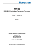
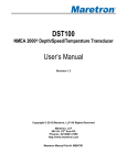
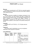
PROFI-5000 User Manual Warranty All products manufactured by ICP DAS are warranted against defective materials for a period of one year from the date of delivery to the original purchaser. Warning ICP DAS assumes no liability for damages consequent to the use of this product. ICP DAS reserves the right to change this manual at any time without notice. The information furnished by ICP DAS is believed to be accurate and reliable. However, no responsibility is assumed by ICP DAS for its use, or for any infringements of patents or other rights of third parties resulting from its use. Copyright Copyright 2013 by ICP DAS Co., LTD. All rights reserved worldwide. Trademark The names used for identification only may be registered trademarks of their respective companies. Revision Note Date 2009/10/01 2012/06/08 Author Version Jeff Ma 1.0 Ryan Lin 1.1 2013/06/18 Ryan Lin 1.2 Revision Release Add PROFI-5017/ PROFI-5017C/ PROFI-5024 Add PROFI-5018 PROFI-5000 Remote I/O Module User Manual (Version 1.2, Nov/2013) -------------1 Table of Content 1. 2. 3. 4. 5. Introduction ..............................................................................................................................3 1.1. Overview ....................................................................................................................3 1.2. Product Information ...............................................................................................3 1.3. Features .....................................................................................................................4 1.4. Specifications...........................................................................................................4 Hardware ...................................................................................................................................7 2.1. Bus Wiring.................................................................................................................7 2.2. PROFIBUS Cable and Transmission Distance ................................................8 2.3. Status Indicator........................................................................................................9 2.4. Connector ................................................................................................................ 11 2.5. Node Address .........................................................................................................12 2.6. Baud rate support .................................................................................................14 2.7. Pin assignment and I/O wiring ..........................................................................15 PROFIBUS DP System .........................................................................................................26 3.1. Power On / Reset ...................................................................................................27 3.2. Wait Parameterization ..........................................................................................27 3.3. Wait Configuration ................................................................................................30 3.4. Data Exchange .......................................................................................................30 3.5. Establish connection with PROFI-5000 ...........................................................39 3.6. Diagnostic Message Report ...............................................................................40 PROFI-5000 Guideline (for SIMATIC Step 7) ..................................................................41 Appendix A:FAQ .................................................................................................................50 PROFI-5000 Remote I/O Module User Manual (Version 1.2, Nov/2013) -------------2 1. Introduction 1.1. Overview PROFIBUS is an open, digital communication system with a wide range of applications, particularly in the fields of factory automation and process automation. PROFIBUS is suitable for both fast, time-critical applications and complex communication tasks. PROFIBUS-DP is a famous protocol that enables simple, fast, cyclic and deterministic process data exchange between Master and assigned Slave. The PROFI-5000 Compact Remote I/O Module is specially designed for the slave device of PROFIBUS DP protocol. To setup PROFIBUS network, users can choose and configure I/O modules by using the GSD file without any other setting tools. 1.2. Product Information Type Digital Output Model PROFI-5045 PROFI-5051 PROFI-5052 PROFI-5053 Description 24-channel Isolated Digital Output 24-channel Isolated Digital Input 12-channel Isolated Digital Input Digital Input 24-channels Dry Contact Non-Isolated Digital Input PROFI-5050 16-channel Non-Isolated Digital Input and 8-channel Non-Isolated Digital Input and Digital Output Digital Output PROFI-5055 8-channel Isolated Digital Input and 8-channel Isolated Digital Output PROFI-5060 8-channel Isolated Digital Input and Power Relay Output 4-channel Relay Output PROFI-5017 8-Ch Isolated Analog Voltage Input Voltage & Analog Current PROFI-5017C 8-Ch Isolated Analog Current Input Input Thermocouple PROFI-5018 10-Ch Isolated Thermocouple Input PROFI-5024 4-Ch Isolated Analog Voltage & Analog Output Current Output PROFI-5000 Remote I/O Module User Manual (Version 1.2, Nov/2013) -------------3 1.3. Features PROFI-5045/ PROFI-5050/ PROFI-5051/ PROFI-5052/ PROFI-5053/ PROFI-5055/ PROFI-5060 Protocol & Hierarchy DP-V0 Slave Supports Transmission Rate 9.6, 19.2, 45.45, 93.75, 187.5, 500, (Kbps) 1500, 3000, 6000, 12000 Transmission Rate Setting detected automatically Address Setting 0~99 set by Rotary switches Indicators PWR and RUN LED I/O modules Configuration Configured by GSD file Network Isolation Protection High Speed iCoupler DC Isolation Protection 3000VDC on PROFIBUS side PROFI-5017/ PROFI-5017C/ PROFI-5018/PROFI-5024 Protocol & Hierarchy DP-V0 Slave Supports Transmission Rate 9.6, 19.2, 45.45, 93.75, 187.5, 500, (Kbps) 1500, 3000, 6000, 12000 Transmission Rate Setting detected automatically Address Setting 0~126 set by Rotary switches or SAA-telegram Indicators PWR LED and RUN LED,ERR LED I/O modules Configuration Configured by GSD file Network Isolation Protection High Speed iCoupler DC Isolation Protection 3000VDC on PROFIBUS side 1.4. Specifications PROFI-5045/ PROFI-5050/ PROFI-5051/ PROFI-5052/ PROFI-5053/ PROFI-5055/ PROFI-5060 PROFIBUS Interface 9-pin D-Sub(Female) PROFIBUS Controller Profichip VPCLS2 PROFIBUS Transceiver ADI ADM2486 iCoupler Isolated transceiver Transmission Rate Up to 12Mbps Power Requirement 10V ~ 40V Power Consumption 1W Operating Temp. -25℃ ~ +75℃ Storage Temp. -30℃ ~ +85℃ PROFI-5000 Remote I/O Module User Manual (Version 1.2, Nov/2013) -------------4 Humidity Dimensions 5% ~ 95%(Non Condensing) 91x128x52 mm PROFI-5017/ PROFI-5017C PROFIBUS Interface 9-pin D-Sub(Female) PROFIBUS Controller Siemens SPC3 PROFIBUS Transceiver ADI ADM2486 iCoupler Isolated transceiver Transmission Rate Up to 12Mbps Power Requirement 10V ~ 40V Power Consumption 3W Operating Temp. -25℃ ~ +75℃ Storage Temp. Humidity Dimensions PROFI-5018 PROFIBUS Interface PROFIBUS Controller PROFIBUS Transceiver Transmission Rate Power Requirement Power Consumption Operating Temp. Storage Temp. Humidity Dimensions PROFI-5024 PROFIBUS Interface PROFIBUS Controller PROFIBUS Transceiver Transmission Rate Power Requirement Power Consumption -30℃ ~ +85℃ 5% ~ 95%(Non Condensing) 91x128x52 mm 9-pin D-Sub(Female) Siemens SPC3 ADI ADM2486 iCoupler Isolated transceiver Up to 12Mbps 10V ~ 40V 3.5W -25℃ ~ +75℃ -30℃ ~ +85℃ 5% ~ 95%(Non Condensing) 91x130x52 mm 9-pin D-Sub(Female) Siemens SPC3 ADI ADM2486 iCoupler Isolated transceiver Up to 12Mbps 10V ~ 40V 4W PROFI-5000 Remote I/O Module User Manual (Version 1.2, Nov/2013) -------------5 Operating Temp. Storage Temp. Humidity Dimensions -25℃ ~ +75℃ -30℃ ~ +85℃ 5% ~ 95%(Non Condensing) 91x128x52 mm PROFI-5000 Remote I/O Module User Manual (Version 1.2, Nov/2013) -------------6 2. Hardware 2.1. Bus Wiring In order to minimize the reflection effect of the signal transmission, PROFIBUS device has to fit with an active terminal resistor at both first node and last node, as shown below However, the number of station in PROFIBUS network is also restricted. According to PROFIBUS specification, it is up to 32 stations connected in a PROFIBUS segment. If more than 32 stations are connected, the PROFIBUS repeater must be used to link the individual bus segments. PROFI-5000 Remote I/O Module User Manual (Version 1.2, Nov/2013) -------------7 2.2. PROFIBUS Cable and Transmission Distance The PROFIBUS cable with following properties has different transmission distance with respect to different transmission rate, shown in the following table 1. 2. 3. 4. 5. Impedance :135~165Ω Capacity : lower than 30 pF/m Loop resistance : lower than 110Ω/Km Wire diameter : larger than 0.65mm Core cross-section : larger than 0.34mm2 Transmission Rate(Kbps) 9.6, 19.2, 45.45, 93.75 187.5 500 1500 3000, 6000, 12000 Transmission Distance per Segment (meter) 1200 1000 400 200 100 PROFI-5000 Remote I/O Module User Manual (Version 1.2, Nov/2013) -------------8 2.3. Status Indicator PROFI-5045/ PROFI-5050/ PROFI-5051/ PROFI-5052/ PROFI-5053/ PROFI-5055/ PROFI-5060 It provides two status indicator, they are PWR LED (red) and RUN LED (green). When the power is supplied to module, PWR LED will turn on; If CHK_CFG procedure is finished, RUN LED will turn on. The table explains the relationship between them. Status Indicator PWR ON & RUN OFF Meaning Master not Ready, or Address not Match or Cfg Fault(Note 2.) PWR ON & RUN ON Module is in clear mode or Operate mode*. Recommend solution 1. Check the address setting of module and DP-master. 2. Sets the DP-Master to operation mode. 3. Make sure of the consistency of Module Selection. N/A PROFI-5017/ PROFI-5017C/ PROFI-5018/ PROFI-5024 It provides three types of status indicator, they are PWR LED (yellow), ERR LED (red) and RUN LED (green). When the power is supplied to module, PWR LED will turn on; If CHK_CFG procedure is finished, RUN LED will turn on and ERR LED will turn off. The table explains the relationship between PROFI-5000 Remote I/O Module User Manual (Version 1.2, Nov/2013) -------------9 them. Status Indicator ERR ON & RUN OFF Meaning Offline Mode Recommend solution Check the address setting of module and DP-master. Stop Mode Check the DP-Master is ready to communicate with module. ERR Flash(2Hz) Prm Fault Check the setting of module in the master interface and make sure of the consistency. ERR Flash(1Hz) Cfg Fault Same as above ERR Flash(10Hz) ERR ON & RUN ON Clear Mode Sets the DP-Master from clear mode to operation mode ERR OFF & RUN ON Operate Mode PWR & ERR Flash lnterlace(2Hz) Diag Exist Check the Input/Output value (Diag. Msg. Request) that if exceed/under the limit Note 1: “Prm Fault” is the abbreviation of “Parameter Fault”; It means that the number of parameter data which receive from DP-Master is not consistency with DP-Slave (PROFI-5017(C)), and it could due to the difference between module installation and master setting. Note 2:“Cfg Fault” is the abbreviation of “Configuration Fault”, it means that the number of configuration data which receive from DP-Master is not consistency with DP-Slave (PROFI-5017(C)), and it could due to the wrong order of installation. Note *: there are four kinds of state in PROFIBUS DP Master. 1. Offline mode: Master not active on the bus. 2. Stop mode: Master only transmit token on the bus, and PROFIBUS DP is not active. 3. Clear mode: DP Master active, but all output are zero or set to fail-safe state. 4. Operate mode: DP Master full active. PROFI-5000 Remote I/O Module User Manual (Version 1.2, Nov/2013) -------------10 2.4. Connector The connector of PROFI-5000 is shown below Pin No. Signal Meaning 3 B-Line Receive/Transmit data - plus 4 CNTR-P Repeater control signal, RTS signal 5 GND Power ground of active terminator 6 VP Power 5 volt of active terminator 8 A-Line Receive/Transmit data - minus Note: The connector of PROFI-5000 has no terminators; users must use the connector with the terminator inside. The power of the terminator will provide by terminal device. PROFI-5000 Remote I/O Module User Manual (Version 1.2, Nov/2013) -------------11 2.5. Node Address According to PROFIBUS specification, the station address which from 0 to 126 is valid, and the address 126 is a special address that supports the remote setting SSA telegram from Class 2 DP-Master. PROFI-5045/ PROFI-5050/ PROFI-5051/ PROFI-5052/ PROFI-5053/ PROFI-5055/ PROFI-5060 - The figure shown above is the decimal rotary switch. It dominates the node (station) address of PROFI-5000. The left side switch is high nibble of address and the other one is low nibble of address. - It doesn’t support SSA service for setting node address. EX 1 : MSB = 2, LSB = 3, node address => (2*10+3) = 23 PROFI-5017/ PROFI-5017C/ PROFI-5018/ PROFI-5024 - The figure shown above is the decimal rotary switch. It dominates the node (station) address of PROFI-5000. The switch is which labeled MSB is high nibble of address and the other one is low nibble of address. - Module applies the setting of rotary switch as its address if the address is valid. While the address is invalid, module loads the pre-saved value from EEPROM. Moreover, if the address is invalid (126) again, module awaits the SSA telegram and applies it. (Note: If you want to clear the setting stored at EEPROM, you just adjust rotary switch to FF before the power supplied). Rotary Pre-saved address SSA Telegram PROFI-5000 Remote I/O Module User Manual (Version 1.2, Nov/2013) Station Address -------------12 Switch(dec) 0~125 126~254 255 (EEPROM) Do not care 0~125 No Accept No Accept 126(default) Accept with address 0~125 127~254 impossible Clear to 126 Accept with address 0~125 Rotary Switch Pre-saved address(EEPROM) SSA Telegram and save address to EEPROM N/A SSA telegram and save address to EEPROM Note 1: Only one DP-Slave station with address 126 permitted in the bus. Note 2: if you want to change the station address after data exchange, PROFI-5017(C) should return to Wait-Prm state and wait for one second to apply the new address. EX 1 : MSB = 0, LSB = B, node address => (0*16+11) = 11 EX 2 : MSB =7, LSB = 9, node address => (7*16+9) = 121 EX 3 : MSB =7, LSB = F, EEPROM = 15, 126 < (7*16+F) = 127 < 254 node Address = Pre-saved address (EEPROM) = 15 EX 4 : MSB = 8, LSB = A, EEPROM = 126, 126 < (8*16+A) = 128 < 254 node Address = SSA Telegram and save address to EEPROM EX 5 : MSB = F, LSB = F, (F*16+F) = 255 Station Address = SSA Telegram and save address to EEPROM PROFI-5000 Remote I/O Module User Manual (Version 1.2, Nov/2013) -------------13 2.6. Baud rate support PROFI-5000 supports the entire baud rates of PROFIBUS. They are 9.6Kbps, 19.2Kbps, 45.45Kbps, 187.5Kbps, 500Kbps, 1.5Mbps, 3Mbps, 6Mbps, and 12Mbps. Because PROFI-5000 has a functionality of auto- detection for baud rates, users don’t need to set the baud rate manually. Note: Many baud rates only are supported by the particular cable or speed. For the detail, please refer to the above section “PROFIBUS Cable and Transmission Distance” PROFI-5000 Remote I/O Module User Manual (Version 1.2, Nov/2013) -------------14 2.7. Pin assignment and I/O wiring PROFI-5045 PROFI-5000 Remote I/O Module User Manual (Version 1.2, Nov/2013) -------------15 PROFI-5050 PROFI-5000 Remote I/O Module User Manual (Version 1.2, Nov/2013) -------------16 PROFI-5051 PROFI-5000 Remote I/O Module User Manual (Version 1.2, Nov/2013) -------------17 PROFI-5052 PROFI-5000 Remote I/O Module User Manual (Version 1.2, Nov/2013) -------------18 PROFI-5053 PROFI-5000 Remote I/O Module User Manual (Version 1.2, Nov/2013) -------------19 PROFI-5055 PROFI-5000 Remote I/O Module User Manual (Version 1.2, Nov/2013) -------------20 PROFI-5060 PROFI-5000 Remote I/O Module User Manual (Version 1.2, Nov/2013) -------------21 PROFI-5017 PROFI-5000 Remote I/O Module User Manual (Version 1.2, Nov/2013) -------------22 PROFI-5017C PROFI-5000 Remote I/O Module User Manual (Version 1.2, Nov/2013) -------------23 PROFI-5018+DB-1820(transformation connector) PROFI-5000 Remote I/O Module User Manual (Version 1.2, Nov/2013) -------------24 PROFI-5024 PROFI-5000 Remote I/O Module User Manual (Version 1.2, Nov/2013) -------------25 3. PROFIBUS DP System The flow chart of the DP-slave Power On / Reset Invalid Address Valid Address / SSA_Telegram Wait Parameter Slave Diagnosis Get Configuration Check Configuration Not Ok Wait Configuration Check Configuration Not Ok / Set Parameter Not Ok Data Exchange Slave Diagnosis Set Parameter OK Get Configuration Data Exchange Check Configuration OK Set Parameter Ok Read Input Read Output Get Configuration Slave Diagnosis Before DP-Slave changes to data exchange state, it employs some telegrams to initialize and establish the connection with DP-Master. These telegrams include Slave Diagnosis (Slave_Diag), Set Parameter (Set_Prm), Check Configuration (Chk_Cfg), Slave Diagnosis, Data Exchange (Data_Exch) and optional global control (GC). The explanation is as follows: PROFI-5000 Remote I/O Module User Manual (Version 1.2, Nov/2013) -------------26 3.1. Power On / Reset While the power supplied, PROFI-5000 loads the value of rotary switches first and decides to apply it immediately. Be attention to duplicate address setting with others, it may occur any unpredictable accident. 3.2. Wait Parameterization In order to establish the connection completely, the DP-Slave should obtain enough information from the DP-Master. The DP-Slave applies the parameterization data to the I/O module of DP-Slave. DP-master divided these parameters into two parts: one is master-related parameter, and another one is module-related parameter. Master-related parameters provide the common setting between DP-Master and DP-Slave (e.g. Byte-Order). Module-related parameters provide the fundamental setting of the I/O modules in DP-Slave. If the parameters have been applied successfully, DP-state will switch to wait configuration, otherwise return to wait parameter. System Parameters - Byte Order Byte order is an important factor related to the memory allocation. Big-endian byte order (Motorola format) allocates more significant byte in lower memory address. On the other hand, little-endian Byte order (Intel format) allocates more significant byte in higher memory address. For example, the integer which value is 0x0400(hex) will allocates 0x40(hex) in the first byte of the memory allocated to the integer and 0x00(hex) in the second byte. PROFI-5045/ PROFI-5050/ PROFI-5051/ PROFI-5052/ PROFI-5053/ PROFI-5055/ PROFI-5060 - Module has no parameterization data. PROFI-5017/ PROFI-5017C PROFI-5017(C) is a standard analog input module; it requires the parameter of “Data Format”, “Data Range” and “Diag Enable” to establish the connection completely. Data range means the measurement type (voltage, current) and range. 1. Volt Inp. Range: +/- 10.0 V 2. Volt Inp. Range: +/- 5.0 V PROFI-5000 Remote I/O Module User Manual (Version 1.2, Nov/2013) -------------27 3. 4. 5. Volt Inp. Range: +/- 2.5 V Volt Inp. Range: +/- 1.25 V Curr Inp. Range: 0 ~20000uA Data format can be selected either engineer unit format or hexadecimal format. 1. Engineer-unit format 2. Hexadecimal format Diag Enable is a flag that determines PROFI-5017(C) whether diagnostic message will report or not. PROFI-5018 PROFI-5018 is a Thermocouple input module; it requires the parameter of “Data Format”, “Filter Selection”, “CJC Enable”, “Channel Enable”, “Diag Enable”, “Type Code” and “CJC-Offset” to establish the connection completely. Data format can be selected either engineer unit format or hexadecimal format. 1. Engineer-unit 2. 2’s Complement HEX Filter Selection can be selected either 60Hz rejection or 50Hz rejection. CJC Enable is a flag that determines PROFI-5018 whether CJC(cold junction compensation) will enable or not. Channel Enable is a flag that determines PROFI-5018 whether current channel will acquisition data or not. Diag Enable is a flag that determines PROFI-5018 whether diagnostic message will report or not. Type Code means the measurement type (voltage, current, temperature) and range. 1. +/- 15 mV 2. +/- 50 mV 3. +/- 100 mV PROFI-5000 Remote I/O Module User Manual (Version 1.2, Nov/2013) -------------28 4. +/- 500 mV 5. +/- 1.0 V 6. +/- 2.5 V 7. +/- 20mA (external 125 Ohm) 8. +4 ~ 20mA (external 125 Ohm) 9. Thermocouple J type 10. Thermocouple K type 11. Thermocouple T type 12. Thermocouple E type 13. Thermocouple R type 14. Thermocouple S type 15. Thermocouple B type 16. Thermocouple N type 17. Thermocouple C type 18. +0 ~ 20mA (external 125 Ohm) CJC Offset is used to adjust CJC. PROFI-5024 PROFI-5024 is a standard analog output module; it requires the data of “Data Format” and “Diag Enable” to establish the connection completely. Data format can be selected either engineer unit format or hexadecimal format and output type (voltage, current). 1. Engineer-unit format(mV) 2. Hexidecimal format(Voltage) 3. Engineer-unit format(mA) 4. Hexidecimal format(Current) 5. Engineer-unit format(uA) Diag Enable is a flag that determines PROFI-5024 whether diagnostic message will report or not. On the other hand, PROFI-5024 has the Safe Value output mechanism. It can output the Safe Value while PROFI-5024 has been changed to stop mode (or offline mode). The safe value can make sure of the correctness of operating. There are three modes in safe value for users: Retain Last Value, Clear Output and Switch to Substitute Value. PROFI-5000 Remote I/O Module User Manual (Version 1.2, Nov/2013) -------------29 “Retain Last Value” is that PROFI-5024 retain the last valid output value for the corresponding channel. “Clear Output” clear the corresponding channel to analog zero volt, analog zero ampere. “Substitute Value” follows Safe mode selection in module parameter, it is setting by user, it must be obey the data range of corresponding data format and type-code. 3.3. Wait Configuration Configuration data generates by configuration tools according to GSD file. The users select the module he wants, and configuration data generate correspondingly. If the module installed is not consistency with configuration, “configuration fault” diagnosis message will report by slave device. 3.4. Data Exchange After the configuration procedure has been accomplished, PROFI-5000 exchanges I/O data with the DP-Master cyclically. In following section, we introduce the Numeric Notation and Byte Order briefly. PROFI-5045/ PROFI-5050/ PROFI-5051/ PROFI-5052/ PROFI-5053/ PROFI-5055/ PROFI-5060 Byte Order It support only little-endian Byte Order. The digital input or output module arrange its data as follow (for example: 4-Byte INPUT). PROFI-5017/ PROFI-5017C PROFI-5000 Remote I/O Module User Manual (Version 1.2, Nov/2013) -------------30 Byte Order PROFI-5017(C) has 8 analog channels. Every channel has 2 bytes. For example, the following figure shows data arrangement of PROFI-5017(C). Note: The order of I/O data is ranked by channel’s identifier, so the channel with lower ID has priority over the channel with higher ID. PROFI-5018 Byte Order PROFI-5018 has 10 analog channels. Every channel has 2 bytes. For example, the following figure shows data arrangement of PROFI-5018. Note: The order of I/O data is ranked by channel’s identifier, so the channel with lower ID has priority over the channel with higher ID. PROFI-5000 Remote I/O Module User Manual (Version 1.2, Nov/2013) -------------31 PROFI-5024 Byte Order PROFI-5024 has 4 analog channels. Every channel has 2 bytes. For example, the following figure shows data arrangement of PROFI-5024. Note: The order of I/O data is ranked by channel’s identifier, so the channel with lower ID has priority over the channel with higher ID. PROFI-5000 Remote I/O Module User Manual (Version 1.2, Nov/2013) -------------32 3.4.1. Numeric Representation PROFI-5017/ PROFI-5017C +/- 10 V : The range for Engineer-Unit: -10000~10000(mV) The range for 2’s complement hexadecimal: 0000~1FFF (0v ~ 10v), 2000~3FFF (-10v~1.22mV) Conversion from Engineer-Unit to 2’s complement hexadecimal: HexValue= EngineerValue × 8192-1 10000 HexValue= EngineerValue × 8192+16384 10000 Measurement Value if 0≦EngineerValue≦10000 if -10000≦EngineerValue<0 Decimal Hexadecimal 10000 0x2710 0 0x0000 -10000 0xD8F0 +10v(Hex mode) 8191 0x1FFF +5v(Hex mode) 4095 0x1000 +10v(Engineer mode) 0v(Engineer mode) -10v(Engineer mode) PROFI-5000 Remote I/O Module User Manual (Version 1.2, Nov/2013) -------------33 0v(Hex mode) 0 0x0000 -5v(Hex mode) 12288 0x3000 -10v(Hex mode) 8192 0x2000 +/- 5 V : The range for Engineer-Unit: -5000~5000(mV) The range for 2’s complement hexadecimal: 0000~1FFF (0v ~ 5v), 2000~3FFF (-5v~0.61mV) Conversion from Engineer-Unit to 2’s complement hexadecimal: HexValue= EngineerValue × 8192-1 5000 HexValue= EngineerValue × 8192+16384 5000 Measurement Value if 0≦EngineerValue≦5000 Decimal if -5000≦EngineerValue<0 Hexadecimal +5v(Engineer mode) 5000 0x1388 0v(Engineer mode) 0 0x0000 -5v(Engineer mode) -5000 0xEC78 +5v(Hex mode) 8191 0x1FFF +2.5v(Hex mode) 4095 0x1000 0v(Hex mode) 0 0x0000 -2.5v(Hex mode) 12288 0x3000 -5v(Hex mode) 8192 0x2000 +/- 2.5 V : The range for Engineer-Unit: -2500~2500(mV) The range for 2’s complement hexadecimal: 0000~1FFF (0v ~ 2.5v), 2000~3FFF (-2.5v~0.3mV) Conversion from Engineer-Unit to 2’s complement hexadecimal: HexValue= EngineerValue × 8192-1 2500 HexValue= EngineerValue × 8192+16384 2500 Measurement Value if 0≦EngineerValue≦2500 Decimal if -2500≦EngineerValue<0 Hexadecimal +2.5v(Engineer mode) 2500 0x09C4 0v(Engineer mode) 0 0x0000 PROFI-5000 Remote I/O Module User Manual (Version 1.2, Nov/2013) -------------34 -2.5v(Engineer mode) -2500 0xF63C +2.5v(Hex mode) 8191 0x1FFF +1.25v(Hex mode) 4095 0x1000 0v(Hex mode) 0 0x0000 -1.25v(Hex mode) 12288 0x3000 -2.5v(Hex mode) 8192 0x2000 +/- 1.25 V : The range for Engineer-Unit: -1250~1250(mV) The range for 2’s complement hexadecimal: 0000~1FFF (0v ~ 1.25v), 2000~3FFF (-1.25v~0.15mV) Conversion from Engineer-Unit to 2’s complement hexadecimal: HexValue= EngineerValue × 8192-1 1250 HexValue= EngineerValue × 8192+16384 1250 Measurement Value if 0≦EngineerValue≦1250 Decimal if -1250≦EngineerValue<0 Hexadecimal +1.25v(Engineer mode) 1250 0x04E2 0v(Engineer mode) 0 0x0000 -1.25v(Engineer mode) -1250 0xFB1E +1.25v(Hex mode) 8191 0x1FFF +0.675v(Hex mode) 4095 0x1000 0v(Hex mode) 0 0x0000 -0.675v(Hex mode) 12288 0x3000 -1.25v(Hex mode) 8192 0x2000 0 ~ 20 mA : The range for Engineer-Unit: 0~20000(uA) The range for 2’s complement hexadecimal: 0000~1FFF (0mA ~ 20mA) Conversion from Engineer-Unit to 2’s complement hexadecimal: HexValue= EngineerValue × 8192-1 20000 Measurement Value if 0≦EngineerValue≦20000 Decimal Hexadecimal 20mA(Engineer mode) 20000 0x4E20 10mA(Engineer mode) 10000 0x2710 PROFI-5000 Remote I/O Module User Manual (Version 1.2, Nov/2013) -------------35 0mA(Engineer mode) 0 0x0000 20mA(Hex mode) 8191 0x1FFF 10mA(Hex mode) 4095 0x1000 0mA(Hex mode) 0 0x0000 PROFI-5018 Type Code Measurement Type 00 -15mV to +15mV 01 -50mV to +50mV 02 -100mV to +100mV 03 -500mV to +500mV 04 -1V to +1V 05 -25V to +25V 06 -20mA to +20mA 7 +4mA to +20mA 0E J Type 0F K Type 10 T Type 11 E Type 12 R Type 13 S Type Data Format Max. Value Min. Value Engineer Unit +15000 -15000 2's Complement HEX 7FFF 8000 Engineer Unit +5000 -5000 2's Complement HEX 7FFF 8000 Engineer Unit +10000 -10000 2's Complement HEX 7FFF 8000 Engineer Unit +5000 -5000 2's Complement HEX 7FFF 8000 Engineer Unit +10000 -10000 2's Complement HEX 7FFF 8000 Engineer Unit +25000 -25000 2's Complement HEX 7FFF 8000 Engineer Unit +20000 -20000 2's Complement HEX 7FFF 8000 Engineer Unit +20000 +4000 2's Complement HEX 7FFF 1999 Engineer Unit +12000 -2100 2's Complement HEX 7FFF E99a Engineer Unit +13720 -2700 2's Complement HEX 7FFF E6D0 Engineer Unit +4000 -2700 2's Complement HEX 7FFF A99A Engineer Unit +10000 -2700 2's Complement HEX 7FFF DD71 Engineer Unit +17650 -500 2's Complement HEX 7FFF FC60 Engineer Unit +17650 -500 2's Complement HEX 7FFF FC60 PROFI-5000 Remote I/O Module User Manual (Version 1.2, Nov/2013) -------------36 14 B Type 15 N Type 16 C Type 1A 0mA to +20mA Engineer Unit +18200 +00000 2's Complement HEX 7FFF 0000 Engineer Unit +13000 -2700 2's Complement HEX 7FFF E56B Engineer Unit +23200 +00000 2's Complement HEX 7FFF 0000 Engineer Unit +20000 +00000 2's Complement HEX 7FFF 0000 PROFI-5024 +/-10V : The range for Engineer-Unit: -10000~10000(mV) The range for 2’s complement hexadecimal: 0000~7FFF (0v ~ 10v), 8000~FFFF (-10v~0.3mV) Conversion from Engineer-Unit to two’s complement hexadecimal: EngineerValue 10000 × 32768-1 if 0≦EngineerValue≦10000 HexValue= EngineerValue 10000 HexValue= × 32768+65536 if-10000≦EngineerValue<0 Measurement Value 10v(Engineer mode) 0v(Engineer mode) -10v(Engineer mode) 10v(Hex mode) 0v(Hex mode) -10v(Hex mode) Decimal 10000 0 -10000 32767 0 -32768 Hexadecimal 0x2710 0x0000 0xD8F0 0x7FFF 0x1000 0x8000 +20mA : The range for Engineer-Unit: -20000~20000(uA) The range for 2’s complement hexadecimal: 0000~7FFF (0v ~ +20mA) Conversion from Engineer-Unit to 2’s complement hexadecimal: EngineerValue 20000 HexValue= × 32768-1 PROFI-5000 Remote I/O Module User Manual (Version 1.2, Nov/2013) -------------37 Measurement Value 20mA(Engineer mode) 0mA(Engineer mode) 20mA(Hex mode) 0mA(Hex mode) Decimal 20000 0 32767 0 Hexadecimal 0x4E20 0x0000 0x7FFF 0x0000 PROFI-5000 Remote I/O Module User Manual (Version 1.2, Nov/2013) -------------38 3.5. Establish connection with PROFI-5000 Before establish the connection between DP-Master and PROFI-5000, user should obey the following step first. First, users must load the electronic device description file(GSD file) of the PROFI-5000(IPDS0C47) into the DP-Master, and select the corresponding modules. Finally change your DP-master from Offline state to Operate state. While DP-Master changes to operate mode, PROFI-5000 will initial the modules and wait for Chk_Cfg telegram in order. If there is no error occurs, PROFI-5000 proceeds into data exchange state. Users can observe the status indicator LED to know the state of PROFI-5000. At the meantime, if there is any error occurs, PROFI-5000 will return to wait configuration. PROFI-5000 Remote I/O Module User Manual (Version 1.2, Nov/2013) -------------39 3.6. Diagnostic Message Report The diagnostic messages report to DP-Master when the DP-Slave has errors or the unusual event occurs. Usually, It report diagnosis due to following standard channel-related event. PROFI-5045/ PROFI-5050/ PROFI-5051/ PROFI-5052/ PROFI-5053/ PROFI-5055/ PROFI-5060 - It doesn’t support diagnostic message report. PROFI-5017/ PROFI-5017C/ PROFI-5018/ PROFI-5024 - It support error code “2”,”3”,”7” and ”8”. - PROFI-5018 support additional error code “5” and “6”. Error Code Error Type 0 Reserved 1 Short Circuit 2 Under-voltage 3 Over-voltage 4 Overload 5 Over-temperature 6 Line/wire Break 7 Upper Limit Value Exceeded (Current) 8 Lower Limit Value Exceeded(Current, Sensor) 9 Error 10~15 Reserved 16~31 Manufacture Specific/Device-Related PROFI-5000 Remote I/O Module User Manual (Version 1.2, Nov/2013) -------------40 4. PROFI-5000 Guideline (for SIMATIC Step 7) In this example, we use Siemens S7-300 PLC (as a PROFIBUS master)、 a PROFI-5017 (as a PROFIBUS slave) to read voltage(9v) from channel 0~channel 7. Step 1:Open “SIMATIC Manager” tool and select “New Project Wizard” to open a new project. PROFI-5000 Remote I/O Module User Manual (Version 1.2, Nov/2013) -------------41 Step 2:Double Click “Hardware” to open “HW Config” Step 3:Install GSD file a. Click “Install GSD File” PROFI-5000 Remote I/O Module User Manual (Version 1.2, Nov/2013) -------------42 b. Select the directory of PROFI-5017’s GSD file(ipds0c47.gsd) and click “OK” c. Click “Install” d. Click “”OK” PROFI-5000 Remote I/O Module User Manual (Version 1.2, Nov/2013) -------------43 Step 4:Setup PROFI-5017 module a. Select PROFI-5000 module b. Add a “PROFI-5017(C) module” PROFI-5000 Remote I/O Module User Manual (Version 1.2, Nov/2013) -------------44 Step 5:Setup the parameters of the PROFI-5017 a. Use the default setting Step 6:Download the HW settings into SIMATIC PLC a. Click “Save and Compile” PROFI-5000 Remote I/O Module User Manual (Version 1.2, Nov/2013) -------------45 b. Click “Download” Step 7:Edit “OB1” a. Double click “OB1” b. Variables used in the example LAD Program PROFI-5000 Remote I/O Module User Manual (Version 1.2, Nov/2013) -------------46 c. Program Step 8:Download the settings into SIMATIC PLC PROFI-5000 Remote I/O Module User Manual (Version 1.2, Nov/2013) -------------47 Step 9:Make sure the RUN LED of the PROFI-5017 is ON. Step 10:read voltage from channel 0~channel 7 PROFI-5000 Remote I/O Module User Manual (Version 1.2, Nov/2013) -------------48 PROFI-5000 Remote I/O Module User Manual (Version 1.2, Nov/2013) -------------49 5. Appendix A:FAQ 1. HOW to reads voltage(9v) from PROFI-5017 (for SIMATIC Step7)? 2. HOW to reads current(10mA) from PROFI-5017C (for SIMATIC Step7)? 3. HOW to sends voltage(9v) from PROFI-5024 (for SIMATIC Step7)? 4. HOW to sends current(10mA) from PROFI-5024 (for SIMATIC Step7)? PROFI-5000 Remote I/O Module User Manual (Version 1.2, Nov/2013) -------------50