1
ZENER
Networking Guide ‐ Modbus SMARTSTART 6000 Series Ethernet
Modbus RS485
IMPORTANT – Read this first !
Ensure every device on the Modbus RS485 serial bus has a unique address. Otherwise abnormal behaviour of the whole bus can occur, potentially inhibiting communication with all devices. Only one network TCP client must control and/or configure a Smartstart® 6000 at any given time. Otherwise conflicts in register writes can arise which may result in unexpected behaviour. Network security must be in place to ensure Smartstart® 6000 behaviour cannot be compromised by unauthorised network clients. On changeover between local and network control and vice versa, the motor may start or stop depending on the state of the new command source (local or network). This may result in an unintentional operation on change of a configuration parameter or on change of state of the “Local” input. The local and network control system (e.g. PLC) must to be designed and configured to satisfy the system’s safety and operational requirements. Start Logic (A53) and/or 3‐wire control can be configured to help avoid unintentional motor starts. Essential Services Override (ESO) request via network should only be used as backup to the normal local ESO request. Contact Zener for more information on the ESO operation and associated risks. This manual must be read in conjunction with the SMARTSTART 6000 Instruction manual. PLEASE NOTE: Current Firmware (Revision 1.20) or earlier does not support the changing of parameters via communications. Smartstart®6000
Contents
1 2 3 4 5 Introduction .................................................................................................................................... 2 1.1 References .............................................................................................................................. 2 1.2 Definitions ............................................................................................................................... 3 Installation ...................................................................................................................................... 4 2.1 Prepare .................................................................................................................................... 4 2.2 Configure ................................................................................................................................. 5 2.3 Connect ................................................................................................................................... 5 2.4 Provision .................................................................................................................................. 5 Network Diagnostics ....................................................................................................................... 6 3.1 Network Status Summary ....................................................................................................... 6 3.2 Network Diagnostic Menu ...................................................................................................... 7 Modbus Application Protocol ......................................................................................................... 8 4.1 Functions ................................................................................................................................. 8 4.2 Exceptions ............................................................................................................................... 8 4.3 Address Map ........................................................................................................................... 8 Device Monitoring and Control ....................................................................................................... 9 5.1 Status Registers ....................................................................................................................... 9 5.2 Control Command Flags Register ............................................................................................ 9 5.3 Network Control Permission ................................................................................................... 9 5.4 Network Control Methods .................................................................................................... 10 5.5 Network Control Timeout and Restoration .......................................................................... 10 5.6 Operating Motor when Network is down ............................................................................. 10 5.7 Local/Network Changeover .................................................................................................. 10 6 Device Configuration ..................................................................................................................... 10 7 Specifications ................................................................................................................................ 11 8 7.1 Specifications – Modbus Application Layer .......................................................................... 11 7.2 Specifications – Modbus over RS485 .................................................................................... 11 7.3 Specifications – Modbus over TCP ........................................................................................ 12 APPENDIX A: Modbus Map ........................................................................................................... 13 Smartstart® 6000 Page 1 I0055 SS6000 Network Guide 1 Introduction
The Smartstart® 6000 includes the following networking features: Modbus RTU over RS485 via embedded interface (2 wire cabling – screw terminals) Modbus over TCP via Ethernet option board (CAT5 cabling – RJ45 connector) Control and monitoring of the SmartStart® via network Motor stops on a network timeout error (soft‐stop or trip options) A programmable input (“Local”) can be configured to facilitate local override Easily configured via the “Network” menu Network access permissions are configurable Display provides comprehensive network diagnostic information 1.1
[1] [2] [3] [4] [5] [6] [7] References
Smartstart® 6000 Series User Manual, IMI0042, Zener Electric (Newcastle) Smartstart® 6000 Series Modbus Address Map, APPENDIX A Modbus Application Protocol Specification V1.1b3 (www.Modbus.org) Modbus over Serial Line Specification and Implementation Guide V1.03 (www.Modbus.org) Modbus Messaging on TCP/IP Implementation Guide V1.0b (www.Modbus.org) Basics of the RS‐485 Standard, Technical Article, B&B Electronics (www.bb‐elec.com) RS‐422 and RS‐485 Applications eBook v1.0, B&B Electronics (www.bb‐elec.com) Smartstart® 6000 Page 2 I0055 SS6000 Network Guide 1.2
AOK AR CAT5 CIDR Client Coast Common CRC Device DHCP ESO FC FE IP LAN LEN Local Master N/C Net N/O OR PC PE PLC Req Rsp RTU SCADA Server Slave TCP T/O Unit ID XC Definitions
All Okay Auto Reset /Restart Category 5 (or 5e) cabling for Ethernet over twisted pair Classless Inter‐Domain Routing (IP address format #.#.#.#/#) A device (e.g. PLC or SCADA) that initiates requests (also see master) Free‐wheel stop The signal common in the EIA/TIA standards Cyclic Redundancy Check (detects communication errors) Electronic component connected to network (client or server) Dynamic Host Configuration Protocol Essential Services Override Function Code (Modbus definition) Framing Error (invalid stop bit) Internet Protocol Local Area Network (e.g. TCP/IP over Ethernet with CAT5 cabling) Length (e.g. length error – packet to short or broken up) A programmable input to force local control (or a general reference to local control) Legacy term for client (e.g. RS485 terminology) Normally Closed Network (or bus) Normally Open Over Run (character overrun error) Personal Computer Parity Error Programmable Logic Controller (network client/master) Request (from client to server) Response (from server back to client) Remote Terminal Unit or a reference to the Modbus binary transmission mode Supervisory Control And Data Acquisition A device (e.g. Smartstart®) that sends responses back to client (also see slave) Legacy term for server (e.g. RS485 terminology) Transmission Control Protocol Timeout Modbus TCP header field used to address serial line slave devices via gateway eXception Code (Modbus definition) Smartstart® 6000 Page 3 I0055 SS6000 Network Guide 2 Installation
2.1
Prepare
Prepare for commissioning by filling in the following check list. Item / Description Set protocol to suit type of network used. Options: Disabled; Modbus/RS485 or Modbus/TCP. Set operation on network timeout. Options: Disabled; Stop On T/O or Trip On T/O. Where Net Control (N02) is enabled, consider need for a force “Local” override input. Set network control timeout to suit system safety requirements (0.1 to 60.0s). Allow configuration / parameter changes over network. THIS IS NOT CURRENTLY AVAILABLE. CONFIGURE Address (1 to 247) Speed/Baud (4800 to 38400 bps) Format (8e1, 8o1, 8n1 or 8n2) Set required static IP Address. Set IP Address to 0.0.0.0 for automatic address assignment (via DHCP). When editing the IP Address, the [RESET] key can be used to zero current value Set IP Mask Bits to number of 1’s in subnet mask (per CIDR). Are site schematics or network cabling guidelines available? Phone number for SCADA control centre (if applicable). CONNECT Have suitable RS485 line terminators been installed at each end of line? Have suitable RS485 line polarisation resistors been installed? Who will program and configure the network PROVISION client (e.g. PLC) to work with the Smartstart®? Modbus / RS485 Modbus / TCP MB / RS485 Category Smartstart® 6000 Page 4 Setting / Notes N01 Net Protocol = N02 Net Control = N03 Net Timeout = N04 Net Config = [NOT AVAILABLE] N10 RS485 Addr = N11 RS485 Speed = N12 RS485 Format = N20 IP Address = ___.___.___.___ N25 IP Mask Bits = /___ I0055 SS6000 Network Guide 2.2
Configure
It is preferable to configure the Smartstart® before connecting it to a live network as incorrect settings could disrupt the network. Press [ENTER] to access the menu system to set and review parameters as per the check list. Press [ESC] to exit the menu system. New settings take effect after menu exit and motor off. Older units may require control supply to be cycled for an IP address change to take effect. 2.3
Connect
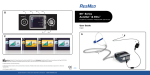
Before wiring the Smartstart®6000, make sure the requirements for shielding, twisted pairs, signal common, line termination and line polarisation are understood (see “Specifications” section). The Smartstart®6000 provides following network terminals. Smartstart® Modbus EIA‐485 Recommended Description Terminal Name [5] Name Wire Colour [5] 17: SCREEN ‐ ‐ Shield Protective ground 22: RS485 DATA+ D1 B/B’ Yellow High when bus idle (Note 2) 23: RS485 DATA‐ D0 A/A’ Brown Low when bus idle (Note 2) 24: RS485 COM Common C/C’ Green Signal common (isolated) ETHERNET PORT ‐ ‐ CAT5 cable RJ45 on RHS of Smartstart® Procedure: 1. Inform system control of task activity (e.g. possible alarms or disruptions) 2. Isolate the Smartstart®6000 (control and power circuits) 3. Wire network cabling to Smartstart®6000 terminals per above table (Notes 2 and 3) 4. Turn Smartstart®6000 on and check Net status on “Clock & Network” screen (e.g. Idle or Live) 5. Inform system control of task completion (e.g. ready to provision for new Smartstart®) Notes: 1. Incorrect configuration can disrupt the network (e.g. address must be unique). 2. Some vendors use A/B naming opposite to the EIA‐485 standard. 3. Unplugging the Modbus RS485 connector also breaks the motor thermistor circuit. 2.4
Provision
The Smartstart®6000 is provisioned into a system by programming and configuring the network client (e.g. PLC). Information is this guide is provided to assist this process. Once provisioned, check the “Clock & Network” screen to confirm Smartstart® is communicating correctly (e.g. Net status shows RxOk or Ctrl). Smartstart® 6000 Page 5 I0055 SS6000 Network Guide 3 NetworkDiagnostics
3.1
NetworkStatusSummary
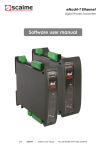
The network status summary is shown on the “Clock & Network” dashboard screen: 17:25:45 Net*
14 Apr 2013 RxOk Status text is shown under “Net” and the top RH corner (*) shows a clockwise rotating event wheel which indicates the approximate rate of network transactions. Status Status Description Text Possible causes / solutions Off
Networking is disabled Boot
Network adapter is initialising Idle
Network is idle (no activity) Live
Network active, but Smartstart® NOT addressed FLT!
Network adapter fault BRK!
Communication break condition ERR!
Communication error occurred Message corrupt (discarded) BAD!
Processing exception occurred Request invalid (discarded) RxOk
Request processed normally Ctrl
Control via network is enabled and online Networking has not been configured. Check setting of N01 Net Protocol parameter. Network adapter option board (e.g. Ethernet) is initialising. Smartstart® is not connected; network client is not connected or not running. A network client is not programmed and/or not provisioned to address the Smartstart®. The Smartstart® network address is not set correctly. Network adapter (e.g. Ethernet option board) not detected or faulty (warning alarm also raised). Network wire is broken, short‐circuited or reverse polarity. Check suitable line terminators and biasing resistors are installed. Check network wiring. Data link settings are incorrect (baud, parity, stop bits, etc.), faulty cabling (wiring, termination, screening) or significant signal interference. Note 1. The Smartstart® is being addressed okay (no data link errors), but request is invalid. Check network client (e.g. PLC) programming. Note 1. Smartstart® is processing requests normally (note that “Ctrl” will override “RxOk”). Smartstart® is receiving and acting on control command requests. Note 2. Notes: 1. The Network Diagnostic menu can be used to further diagnose communications errors (ERR!) and request exceptions (BAD!). See next section for more information. 2. The “Ctrl” status text indicates Smartstart® is being controlled by a network client (Net Control Online). The “Ctrl” message is disabled when the “Local” input is asserted irrespective of received requests (e.g. back to “RxOk” message). See section “Smartstart® Control” for more information. Smartstart® 6000 Page 6 I0055 SS6000 Network Guide 3.2
NetworkDiagnosticMenu
The “Network Diag” menu provides comprehensive network diagnostic information including the diagnostic counters as defined in the Modbus specification [5]. Press the [RESET] key to clear the counters. Use this menu to diagnose network communication and/or measure transaction rate. Network Diagnostic Description Screen Net Status Ctrl* Network status text and event wheel as per “Network Status Summary”. Diag Flags 003Ah Network Diagnostic Flags (in hex) as per Smartstart® Modbus map [2]. C0:ReqsAok 12345 Count of requests processed normally. Note 2. C1:BusMsgs 12345 Count of error‐free bus messages. Note 4. C2:BusErrs 12345 Count of bus messages with a communication error. Note 4. FE PE OR LEN CRC Shows “No comms errors” or lists the type of errors detected. Note 5. C3:ReqsBad 12345 Count of bad requests received. A001 FC016 XC002 Shows “No exceptions” or the last exception (bad request). Note 6. C4:ReqsRxd 12345 Count of requests received (with or without exceptions). A001 FC023 okay
Shows “No requests” or the last function code. Note 6 and 7. C5:ReqCast 12345 Count of broadcast requests received. C6:RspNaks 12345 Count of exception responses sent. C7:RspBusy 12345 Count of busy responses sent (always zero for Smartstart®). C8:OvrRuns 12345 Count of messages detected with a character overrun error. Notes: 1. Press [RESET] to clear all diagnostic registers and counters (only when in this menu). 2. C0 is the event counter described in [4] for FC 11 “Get Comm Event Counter”. 3. C1 to C8 correspond to the serial line diagnostic counter numbering as defined in [5]. 4. Regarding C1 & C2, the Smartstart® does not error check messages to/from other devices. 5. Errors shown: framing, parity, overrun, length and CRC (FE, PE, OR, LEN & CRC). 6. Shows device address (A) & function code (FC). If applicable exception code (XC) is shown. A000 indicates a broadcast request. Meanings of exception codes (XC) are listed in [4]. 7. For Modbus/TCP, the device address (A) is the “Unit Identifier” from the Modbus/TCP header. Smartstart® 6000 Page 7 I0055 SS6000 Network Guide 4 ModbusApplicationProtocol
The Modbus application protocol is defined in [4]. Modbus communications can be used to monitor, and control the Smartstart®. The ability to configure via the network is currently not available. Modbus/RS485 and Modbus/TCP share the same application layer protocol and functionality. 4.1
Functions
Supported Modbus Functionality Supported Modbus Function Codes Read 16‐bit registers FC 03, 04 & 23 Write 16‐bit registers FC 06, 16 & 23 Notes: 1. A full list of supported function codes is given in “Specifications”. 2. Input registers overlap and Holding registers (i.e. FC 03 and 04 are equivalent). 3. FC 23 (read & write) can be used to efficiently monitor and control the Smartstart®. 4.2
Code XC 01 XC 02 XC 03 XC 11 Exceptions
Name Illegal Function Illegal Data Address Illegal Data Value Gateway target device failed to respond Meaning Request contained an unsupported function code Request referenced an undefined register address (i.e. not in [2]) Error in request format (e.g. implied length is incorrect). Note 1. The Smartstart® did not respond to a Modbus/TCP request. Check Net Protocol is set to Modbus/TCP. Notes: 1. XC 03 does NOT cover range error of data written to registers. The client should read back values where data validation is required. 4.3
AddressMap
The Smartstart® Modbus Address Map is fully defined in [2]. The address space consists of: Group Name Access Data Type Comments Device Identification Read Only Static Product information. Trip Log Read Only Persistent Log of last 10 trips. Operation History Read Only Persistent Counters, meters, etc. Operation Status Read Only Dynamic Live status of Smartstart® operation. Network Diagnostics Read Only Dynamic Network diagnostic flags and counters Device Control Read/Write Dynamic See section “Smartstart® Control”. Note 3. Device Configuration Read/Write Dynamic / See section “Smartstart® Configuration”. stored THIS FEATURE IS CURRENTLY NOT AVAILABLE Notes: 1. Any attempt to access an undefined register returns an exception response (XC 02). 2. Any attempt to write to a read‐only register returns an exception response (XC 02). 3. Some registers can be write‐protected (e.g. by configuration and/or Local input asserted). Attempting to write to a protected register returns a normal response even though data is discarded. The client can read back register values when validation is required. FC 23 can be used to write and read in a single request for efficient validation of changes. 4. To avoid unexpected behaviour, ensure only one Modbus client writes to registers. 5. Ensure network security is in place to prevent writes from unauthorised clients. Smartstart® 6000 Page 8 I0055 SS6000 Network Guide 5 DeviceMonitoringandControl
The Smartstart®6000 can be monitored and/or controlled via a network. For information on local monitoring and control, see [1] and [3]. 5.1
StatusRegisters
A network client can read registers (as defined in [2]) to monitor the status of Smartstart® at any time, irrespective of Net Control (N02) setting or Force Local mode. The register space includes device identification, trip log, operation history, operation status and network diagnostics. A network client can use status information to assist with the control of the Smartstart®6000 and/or other system devices. 5.2
ControlCommandFlagsRegister
A network client can control the Smartstart®6000 by regularly writing to the Control Command Flags register (see [2]). The following control flags are supported. Flag Description Reset 0‐>1 = Attempts to reset trip alarm. Motor may start. Enable 1 = enables start and run of motor; 1‐>0 = initiates motor stop Start 1 = start motor (provided Enable on and other conditions permit start) Coast 1 = force free‐wheel stop ESO 1 = Essential services override request (overrides protection). Note 4. Notes: 1. Acceptance of Start flag is per Start Logic (A53) setting (level or edge sense). 2. Enable and Start can be logically coupled for simple run/stop control. Keeping the Enable and Start flags asserted makes system highly available (when set for level sense start logic) and motor will auto start whenever conditions permit (e.g. network restoration, trip reset, restoration of line supply, activation of local enable input, etc.). 3. Where unintentional start must be avoided, review Start flag PLC logic, Start Logic (A53) setting and/or Net Control (N02) setting (e.g. trip on network timeout). 4. ESO is only available when a programmable input has been configured for ESO (Inputs menu). Network ESO request requires: Enable=1, Start=1, Coast=0 and ESO=1. Network ESO request should only be used as a backup of the local ESO request. ESO operation overrides all starter and motor protection and can void Smartstart® warranty. 5.3
NetworkControlPermission
Network control of the Smartstart® is only permitted when ALL of the following are satisfied: “Net Control” parameter is set to enable network control (i.e. not “Disabled”) “Local” input (D1 or D2) is NOT asserted (or not configured) to force local control. Enable (EN) input is asserted; AND Network client (e.g. PLC) is regularly writing to the Control Command register. Smartstart® 6000 Page 9 I0055 SS6000 Network Guide 5.4
NetworkControlMethods
There are number of terminal wiring options to support network control with or without Force Local support (override network control). The following is applicable when Net Control (N02) is enabled. Control Method Network Only Network with Local Stop Network with Simple Override Network with Classic Override 5.5
Inputs Used Enable (bridged) Enable (switched) Enable & Local Enable, Local & Start Description Enable is bridged to +24VDC. Motor start and stop are only controlled by the network client. Local control is not available. Enable is to N/C switch to provide local stop control. There is no provision to force local start. Closing switch may initiate a motor start (where PLC logic asserts Enable and Start flags). Enable and Local are wired to a three (3) position changeover switch (e.g. RUN/STOP/AUTO).This is simplest way to Force Local control of motor start and motor stop. Enable and Local are wired to a three (3) position changeover switch (e.g. LOCAL/OFF/REMOTE). Start is wired to N/O [START] button. Start input is only functional in Force Local mode (“Local” asserted). NetworkControlTimeoutandRestoration
The motor stops when writes to the Control Command Flags register cease for Net Timeout (N03). The stop behaviour (normal stop or trip) is defined by the Net Control (N02) parameter. On restoration of network communications, the motor may automatically start (when network Enable and Start flags are on). This can be avoided by having PLC logic use a pulse timer for motor start, setting Start Logic (A53) to edge sense, and/or setting Net Control (N02) to Trip on T/O. After a NET TIMEOUT trip and after network restoration, the PLC can toggle the reset bit to clear the trip alarm. 5.6
OperatingMotorwhenNetworkisdown
If it is necessary to be able to run a motor when the network (or network client) is down, the Smartstart® will need to change to a “Local Only” mode. Be aware that the motor may start on changeover. Options to change over to a local control mode are: Operate a changeover switch to “Force Local” (assert the “Local” input); or Change the “Net Control” parameter to “Disabled” to permit local control. 5.7
Local/NetworkChangeover
Changing the state of the “Local” input (Force Local mode) or the Net Control (N02) setting can change the control source. Bump‐less transfer is supported when control signals are same as previous source. Depending on the state of the new control signals (Enable, Start, Stop & Coast), the motor may start or stop on changeover. 6 DeviceConfiguration
The current firmware does not support the configuration or the changing of Soft Starter parameters via the network. If this feature is required contact Zener for more details . Smartstart® 6000 Page 10 I0055 SS6000 Network Guide 7 Specifications
7.1
Specifications–ModbusApplicationLayer
Item (Note) Function Codes Exception Codes Reachable Registers Diagnostics 7.2
Description FC 03 Read Input Registers (max 125) FC 04 Read Holding Registers (max 125) FC 06 Write Single Register FC 16 Write Multiple Registers (max 123) FC 23 Read/Write Multiple Registers (max 121) XC 01 Illegal Function XC 02 Illegal Data Address XC 04 Illegal Data Value XC 11 Gateway target device failed to respond (Modbus/TCP only) Defined in document: “Smartstart® 6000 Modbus Map” Available on display: status text, event wheel, diagnostic flags (including communication errors), diagnostic counters (per Modbus specification), last function code & last exception code. Notes
Specifications–ModbusoverRS485
Item Implementation Class Description Default / Notes All “basic” requirements. Most “regular” requirements (excludes ASCII transmission mode and 4 wire cabling). Addressing 0 to 247 0, Note 1 Baud Rate (bps) 4800, 9600, 19200 & 38400 19200 Parity ODD, EVEN, NO (8o1, 8e1, 8n1 & 8n2) EVEN, Note 2 Configurable Yes (address, baud rate and parity) Broadcast Yes Transmission Mode Binary RTU only Electrical Interface RS485 2 wire cabling (1 twisted pair plus Common) Note 3 Connector Type Screw terminals (Data+, Data‐, Common & Screen) Grounding Common is isolated (ground/screen terminal available) Note 4 Line Isolation Yes (internal isolated RS485 transceiver) Line Termination Not provided Note 5 Line Polarisation Lightweight only (internal 10K pull up/down resistors) Note 6 Notes: 1. When address is set to zero (default), only broadcast requests are processed. 2. The 10 bit character format (8n1) is not compliant with the Modbus specification [5], but is supported for compatibility with other systems. 3. Shielded cable with two twisted pairs is recommended. Use one pair for circuit “Common” and other pair for balanced data lines. Connect shield of each cable segment to protective ground at one end only. 4. The “Common” circuit must be connected to all devices on the bus and connected directly to protective ground (at one point only, typically near the master device). “Screen” terminal provides a local protective ground (e.g. for cable shield). 5. It is required to place a Line Terminator near each of the two ends of the bus [5]. A capacitor (1nF) in series with a resistor (120 Ohms) is recommended for both Line Terminators [5]. 6. Line polarisation (450 to 650 Ohms pull up and pull down) is recommended [5], typically near the master device. Smartstart® 6000 Page 11 I0055 SS6000 Network Guide 7.3
Specifications–ModbusoverTCP
Item Implementation Addressing Description Default / Notes Modbus TCP/IP server Static IP address or assigned via DHCP. Standard Modbus TCP port 502. Accepts any Unit Identifier. Note 1. Configurable Yes. IP address and subnet mask bits. Set IP Address to 0.0.0.0/24 0.0.0.0 to enable assignment via DHCP. (DHCP) Network Interface RJ45 Ethernet 10Base‐T or 100Base‐TX (auto‐sensing) LEDs Ethernet Link Activity (on RJ45 connector) Isolation Yes (via Ethernet magnetics) Diagnostics Net “Boot” displayed while Ethernet adapter boots up. Net Check correct “FLT!” and warning “W08 ETH PORT FLT” displayed on boot option board is failure. Other diagnostics as per Modbus application layer. fitted Exception Codes XC 11 Gateway target device failed to respond. This Check “N01 Net (unique to indicates that Modbus/TCP client connected the Ethernet Protocol” is set Modbus/TCP) adapter okay, but the Smartstart® is not responding. correctly Notes: 1. The Smartstart®6000 is addressed by IP address and will respond irrespective of value in the Unit Identifier field (Modbus header). Smartstart® 6000 Page 12 I0055 SS6000 Network Guide 8 APPENDIXA:ModbusMap
Smartstart® 6000 Page 13 I0055 SS6000 Network Guide Zener SMARTSTART 6000
Modbus Map
Classic Hex. Decimal Bit No. GROUP NAME / Data Item Name
Number Address Address
41025
41026
41027
41028
41029
41030
41031
0x0400
0x0401
0x0402
0x0403
0x0404
0x0405
0x0406
41033
0x0408
41034
41035
41036
41039
41042
41045
41048
41051
41054
41057
41060
0x0409
0x040A
0x040B
0x040E
0x0411
0x0414
0x0417
0x041A
0x041D
0x0420
0x0423
1024
1025
1026
1027
1028
1029
"
"
"
1030
1032
"
"
1033
1034
1035
1038
1041
1044
1047
1050
1053
1056
1059
SS6K_Modbus_Map_V1.2
0
1
2
DEVICE IDENTIFCATION
Product Identifer
Firmware version number
Firmware revision letter
Product Series
Product Rating (full load current)
Product Option Flags . . .
/ Custom Model
/ Six Wire Support
/ Reserved (to bit 15)
Reserved
Reg. Data Type
Count
1
1
1
1
1
1
UINT16
UINT16
ASCII[1]
ASCII[2]
UINT16
BOOLEAN
BOOLEAN
BOOLEAN
V1.2 for SS6K firmware V1.20
Units
0.01
0.1A
Comment
Static/constant data (read only)
0x5560 for SMARTSTART 6000
100 to 999 (version 1.00 to 9.99)
32 (' ') for none, 65 to 90 ('A' to 'Z')
"6E", "6R", "6V" etc (e.g. 0x3652 for "6R")
e.g. 30 to 8300 for 3A to 830A models
See below . . .
1 = Special customised model
1 = Model supports 6 wire installation
2
TRIP LOG
Persistent data (read only**)
Trip Log 1: Trip Info . . .
1
. . .
Information about last trip (most recent) . . .
UINT8 (low)
ENUM Operating state at time of trip
0..7 / Operating State
UINT8 (high)
code Cause of trip (see T## codes in user manual)
8..15 / Trip Code
Trip Log 1: Trip Date (month & day)
1
BCD16
mmdd Date of trip (e.g. 0x1231 for December 31st)
Trip Log 1: Trip Time (hour & minute)
1
BCD16
hhmm Time of trip (e.g. 0x2359 for 23:59 = 11:59 PM)
Trip Log 2
3
As above
L02 trip info, date and time
Trip Log 3
3
"
L03 "
Trip Log 4
3
"
L04 "
Trip Log 5
3
"
L05 "
Trip Log 6
3
"
L06 "
Trip Log 7
3
"
L07 "
3
"
L08 "
Trip Log 8
Trip Log 9
3
"
L09 "
Trip Log 10
3
"
L10 " (oldest trip)
NOTE: The trip log has entries for the last 10 trips. Trip log 1 (L01) is the most recent trip (i.e. last trip), while trip log 10 (L10) is the oldest trip. Each entry has the same format (3 registers each). If a trip has not been logged, the log registers read as zero. The "Trip Info" register includes the operating state at the time of trip and cause of trip (see "Operating State" and "Trip Code" registers for more information). Trip date and time are encoded in binary coded decimal. The trip log can be cleared using the "Commands" menu.
30/06/2014
APPENDIX A ‐ 1
Zener SMARTSTART 6000
Modbus Map
Classic Hex. Decimal Bit No. GROUP NAME / Data Item Name
Number Address Address
41063
41065
41067
41069
41071
41072
0x0426
0x0428
0x042A
0x042C
0x042E
0x042F
Units
Comment
OPERATION HISTORY
Persistent data (read only**)
Energy Meter (kWh)
2
UINT32
0.1 kWh Rollover after 99999999.9 (9 digits)
Operating Meter (hrs)
2
UINT32
0.1 hr "
Start Counter
2
UINT32
count Rollover after 999999999 (9 digits)
Trip Counter
2
UINT32
count "
NOTE: Meters and counters are viewable via the dashboard screens and can be cleared via the "Command" menu.
1062
1064
1066
1068
1070
"
"
"
"
"
"
"
"
"
"
"
"
"
"
"
"
0
1
2
3
4
5
6
7
8
9
10
11
12
13
14
15
1071
"
"
"
"
0
1
2
3
SS6K_Modbus_Map_V1.2
Reg. Data Type
Count
V1.2 for SS6K firmware V1.20
OPERATION STATUS
Dynamic data (read only)
Protection Threshold Flags . . .
1
. . .
BOOLEAN
1 = starter too hot to start (Ts > reset temp.)
/ Starter Thermal Hot
/ Motor Thermal Hot
BOOLEAN
1 = motor too hot to start (i2t TOL > reset level)
/ Motor Overtemp Hot
BOOLEAN
1 = motor too hot to start (thermistor > ~1k6 ohms)
/ Alarm Input D1 Detect
BOOLEAN
1 = trip input prewarning (e.g. low pressure)
/ Alarm Input D2 Detect
BOOLEAN
1 = trip input prewarning (e.g. low flow)
/ Acceleration Overtime Detect
BOOLEAN
1 = accel timer expired AND NOT up to speed
/ Current Imbalance Detect
BOOLEAN
1 = imbalance deteteced (prewarning)
/ Motor Stall Detect
BOOLEAN
1 = stall current detected (prewarning)
BOOLEAN
1 = heavy load detected (prewarning)
/ Motor Overcurrent Detect
/ Motor Overtorque Detect
BOOLEAN
1 = heavy load detected (prewarning)
/ Motor Undercurrent Detect
BOOLEAN
1 = light load detected (prewarning)
/ Motor Undertorque Detect
BOOLEAN
1 = light load detected (prewarning)
/ Voltage Imbalance Detect
BOOLEAN
1 = imbalance deteteced (prewarning)
/ Reserved
BOOLEAN
/ Reserved
BOOLEAN
/ Other Alarm Detect
BOOLEAN
1 = Another alarm input condition is active
NOTE: Above can be used for prewarning indication (e.g. threshold exceeded)
Protection Warning Flags . . .
1
. . .
/ Starter Thermal Warning
BOOLEAN
1 = thermal level above "Warn Level"
/ Motor Thermal Warning
BOOLEAN
1 = "
/ Motor Overtemp Warning
BOOLEAN
1 = near trip point (Rt > ~1k6 ohms)
BOOLEAN
1 = trip timer greater than "Warn Delay"
/ Alarm Input D1 Warning
30/06/2014
APPENDIX A ‐ 2
Zener SMARTSTART 6000
Modbus Map
Classic Hex. Decimal Bit No. GROUP NAME / Data Item Name
Number Address Address
41073
0x0430
"
"
"
"
"
"
"
"
"
"
"
"
4
5
6
7
8
9
10
11
12
13
14
15
1072
"
"
"
"
"
"
"
"
"
"
"
"
"
"
"
"
0
1
2
3
4
5
6
7
8
9
10
11
12
13
14
15
SS6K_Modbus_Map_V1.2
Reg. Data Type
Count
V1.2 for SS6K firmware V1.20
Units
Comment
/ Alarm Input D2 Warning
BOOLEAN
1 = "
/ Acceleration Overtime Warning
BOOLEAN
1 = "
/ Current Imbalance Warning
BOOLEAN
1 = "
/ Motor Stall Warning
BOOLEAN
1 = "
/ Motor Overcurrent Warning
BOOLEAN
1 = "
BOOLEAN
1 = "
/ Motor Overtorque Warning
/ Motor Undercurrent Warning
BOOLEAN
1 = "
/ Motor Undertorque Warning
BOOLEAN
1 = "
/ Voltage Imbalance Warning
BOOLEAN
1 = "
/ Reserved
BOOLEAN
/ Reserved
BOOLEAN
/ Other Alarm Warning
BOOLEAN
1 = Another alarm warning (see Warning Code)
NOTE: Above gives pre‐trip warning indication ("Warning Code" gives highest priority warning)
Protection Trip Flags . . .
1
. . .
1 = starter thermal overload/overtemp trip
BOOLEAN
/ Starter Thermal Trip
1 = motor i2t thermal overload trip
/ Motor Thermal Trip
BOOLEAN
1 = motor overtemp (Rt reached 3k ohms)
/ Motor Overtemp Trip
BOOLEAN
1 = external trip input timeout
/ Alarm Input D1 Trip
BOOLEAN
1 = external trip input timeout
/ Alarm Input D2 Trip
BOOLEAN
1 = timeout waiting for motor to get up to speed
/ Acceleration Overtime Trip
BOOLEAN
1 = imbalance timeout
/ Current Imbalance Trip
BOOLEAN
1 = motor stalled
/ Motor Stall Trip
BOOLEAN
1 = heavy load timeout
/ Motor Overcurrent Trip
BOOLEAN
1 = heavy load timeout
/ Motor Overtorque Trip
BOOLEAN
1 = light load timeout
/ Motor Undercurrent Trip
BOOLEAN
1 = light load timeout
/ Motor Undertorque Trip
BOOLEAN
1 = imbalance timeout
/ Voltage Imbalance Trip
BOOLEAN
/ Reserved
BOOLEAN
/ Reserved
BOOLEAN
/ Other Alarm Trip
BOOLEAN
1 = Another alarm has tripped (see Trip Code)
NOTE: Above is a subset of trip conditions. Other trip conditions can be decoded by testing the "Trip Code" register.
30/06/2014
APPENDIX A ‐ 3
Zener SMARTSTART 6000
Modbus Map
Classic Hex. Decimal Bit No. GROUP NAME / Data Item Name
Number Address Address
41074
41075
41076
0x0431
0x0432
0x0433
1073
"
"
"
"
"
"
"
"
"
"
"
"
"
"
"
"
1074
"
"
"
"
"
"
"
"
1075
"
"
SS6K_Modbus_Map_V1.2
0
1
2
3
4
5
6
7
8
9
10
11
12
13
14
15
0
1
2
3
4
5
6
7
0
1
Input/Output Flags . . .
/ Control Supply Healthy
/ Line Supply On
/ Line Rotation 123 (Fwd)
/ Line Rotation 321 (Rev)
/ Enable Input (EN)
/ Digitial Input 1 (D1)
/ Digitial Input 2 (D2)
/ Thermistor Input
/ Current Sensed
/ Motoring (+ve power)
/ Regenerating (‐ve power)
/ Reserved
/ Relay Output 1 / Relay Output 2
/ Relay Output 3
/ Relay Output 4
Programmable Input Flags . . .
/ Trip Input
/ Reset Input
/ Start Input
/ Stop Input
/ Coast Input
/ Local Input
/ ESO Input
/ Reserved (to bit 15)
Programmable Signal Flags . . .
/ Trip Signal
/ Reset Signal
Reg. Data Type
Count
1
BOOLEAN
BOOLEAN
BOOLEAN
BOOLEAN
BOOLEAN
BOOLEAN
BOOLEAN
BOOLEAN
BOOLEAN
BOOLEAN
BOOLEAN
BOOLEAN
BOOLEAN
BOOLEAN
BOOLEAN
BOOLEAN
1
BOOLEAN
BOOLEAN
BOOLEAN
BOOLEAN
BOOLEAN
BOOLEAN
BOOLEAN
BOOLEAN
1
BOOLEAN
BOOLEAN
30/06/2014
V1.2 for SS6K firmware V1.20
Units
Comment
. . .
1 = on; 0 = PSU dip/brownout
1 = three phase line supply on (L1, L2, L3)
1 = line on with forward rotation sequence
1 = line on with reverse rotation sequence
1 = on/closed (local start/stop control)
1 = on/closed (programmable input)
1 = on/closed (programmable input)
1 = okay/closed/cold (Rt < ~1k6 ohms)
1 = CTs sensing current
1 = power going to motor
1 = power returning to line supply
1 = on/closed (programmable relay)
1 = on/closed (programmable relay)
1 = on/closed (programmable relay)
1 = on/closed (programmable relay)
. . .
1 = trip request (e.g. low oil pressure)
1 = reset trip request (e.g. panel keyswitch)
1 = start request at terminals (e.g. start button)
1 = stop request at terminals
1 = coast request at terminals
1 = request "Force Local" (disable net ctrl & cfg)
1 = local ESO request (overrides protection!)
. . .
1 = post delay signal
1 = post delay signal
APPENDIX A ‐ 4
Zener SMARTSTART 6000
Modbus Map
Classic Hex. Decimal Bit No. GROUP NAME / Data Item Name
Number Address Address
41077
41078
41079
0x0434
0x0435
0x0436
"
"
"
"
2
3
4
5
"
"
1076
"
"
1077
"
"
"
"
"
"
"
"
"
"
"
"
"
1078
"
"
"
"
"
"
6
7
SS6K_Modbus_Map_V1.2
Reg. Data Type
Count
/ Start Signal
/ Stop Signal
/ Coast Signal
/ Local Signal
/ ESO Signal
/ Reserved (to bit 15)
Active Alarm
0..7 / Alarm Code
8..15 / Alarm Type
Special Mode Flags . . .
0 / Reserved
1 / Reserved
2 / Torque Control Active
3 / Voltage Control Active
4 / Current Limiting Active
5 / ESO Request
6 / ESO Proof
7 / Any Trip Override
8 / Starter Trip Override
9 / Starter Stressed (persistent flag)
10 / AR Pending
11 / AR Lockout
12 / Reserved (to bit 15)
Auxiliary Status Flags . . .
0 / Prewarning
1 / Warning
2 / Tripped
3 / Standby
4 / Ready
5 / Local Control Only
V1.2 for SS6K firmware V1.20
Units
Comment
BOOLEAN
BOOLEAN
BOOLEAN
BOOLEAN
1 = post delay signal
1 = post delay signal
1 = post delay signal
1 = post delay signal
BOOLEAN
BOOLEAN
1 = post delay signal
1
UINT8 (low)
UINT8 (high)
1
BOOLEAN
BOOLEAN
BOOLEAN
BOOLEAN
BOOLEAN
BOOLEAN
BOOLEAN
BOOLEAN
BOOLEAN
BOOLEAN
BOOLEAN
BOOLEAN
BOOLEAN
1
BOOLEAN
BOOLEAN
BOOLEAN
BOOLEAN
BOOLEAN
BOOLEAN
30/06/2014
code
ENUM
Highest priority active alarm
Alarm code (0..99). See codes in user manual
Alarm type. 0=interlock; 1=warning & 2=trip.
. . .
1 = torque control active (accel or decel)
1 = voltage control active (kick, accel or decel)
1 = current limiting active (accel or decel)
1 = ESO request (local or via network)
1 = ESO request, motor on and current sensed
1 = starter on with any trip alarm (ESO)
1 = starter on with "starter" trip overriden (ESO)
1 = starter has been over stressed (void warranty)
1 = automatic trip reset is pending (could restart)
1 = AR lockout on final trip (after AR Attempts)
. . .
1 = protection threshold exceeded
1 = warning alarm (see Warning Code)
1 = latched trip/fault alarm (see Trip Code)
1 = standing by for line power‐up start (local only)
1 = only waiting for Enable/Start command 1 = force local control or net control disabled
APPENDIX A ‐ 5
Zener SMARTSTART 6000
Modbus Map
Classic Hex. Decimal Bit No. GROUP NAME / Data Item Name
Number Address Address
41080
41081
0x0437
0x0438
"
"
"
"
"
"
"
"
"
1079
"
"
"
"
"
"
"
"
"
"
"
"
"
"
"
1080
SS6K_Modbus_Map_V1.2
6
7
8
9
10
11
12
13
14
0
1
2
3
4
5
6
7
8
9
10
11
12
13
14
Reg. Data Type
Count
V1.2 for SS6K firmware V1.20
Units
Comment
/ Local Enable Command
BOOLEAN
1 = local control enable conditions
/ Local Start Command
BOOLEAN
1 = local start request
/ Net Control Only
BOOLEAN
1 = net control enabled AND NOT force local
/ Net Control Online
BOOLEAN
1 = network control command accepted
/ Net Enable Command
BOOLEAN
1 = network control enable conditions
/ Net Start Command
BOOLEAN
1 = network start request
/ Wait Delay (cooling)
BOOLEAN
1 = motor off delay or waiting to cool (mtr|str)
/ Start Delay Active
BOOLEAN
1 = start requested, but start is being delayed
BOOLEAN
/ Reserved (to bit 15)
Operating Status Flags . . .
1
. . .
/ Line Control
BOOLEAN
1 = external line contactor on/close command
/ Reserved
BOOLEAN
/ Fan Control
BOOLEAN
1 = internal fan on/run command
/ Operating
BOOLEAN
1 = motor on/energised (SCRs or bypass)
/ Ramping
BOOLEAN
1 = regulating conduction (kick, accel or decel)
BOOLEAN
1 = ramp up active (starting, includes kick start)
/ Starting
/ Kick Start
BOOLEAN
1 = kick start boost active
/ Overtime BOOLEAN
1 = accel timer expired and NOT Up To Speed
/ Up To Speed
BOOLEAN
1 = at operating speed (continuous or bypass)
/ Run Mode
BOOLEAN
1 = Up To Speed AND accel timer expired
/ Bypass Control
BOOLEAN
1 = bypass contactor on/close command
/ Continuous
BOOLEAN
1 = SCRs continuously firing
/ Reserved
BOOLEAN
/ Stopping
BOOLEAN
1 = ramp down active (stopping/decel)
/ Reserved (to bit 15)
BOOLEAN
Last Warning Code
1
UINT16
code Cause of last warning (see W## codes in manual)
NOTE: Warning conditions do not inhibit starter operation. The value indicates the cause of the last warning and corresponds to the "W##" value shown on the display (see SMARTSTART User Manual). When there are multiple warnings, the highest priority warning is given. This code can be used to identify specific warnings not covered by "Protection Warning Flags".
30/06/2014
APPENDIX A ‐ 6
Zener SMARTSTART 6000
Modbus Map
Classic Hex. Decimal Bit No. GROUP NAME / Data Item Name
Number Address Address
41082
0x0439
1081
41083
0x043A
1082
41084
41085
41086
41087
41088
0x043B
0x043C
0x043D
0x043E
0x043F
1083
1084
1085
1086
1087
SS6K_Modbus_Map_V1.2
Reg. Data Type
Count
V1.2 for SS6K firmware V1.20
Units
Comment
Last Trip Code
1
UINT16
code Cause of last trip (see T## codes in user manual)
NOTE: Above indicates the cause of the last trip and corresponds to the "T##" value shown on the display (see SMARTSTART User Manual). This code can be used to identify specific trips not covered by "Protection Trip Flags".
Operating State
1
UINT16
ENUM Current operating state
Val : (op code) Name and description
0 : ('O') Off. Line off AND enable off.
1 : ('S') Standby. Line off AND enable on (waiting for line supply).
2 : ('R') Ready. Line on AND enable off (waiting for start request).
3 : ('Y') Start request/delayed (cooling or min off time active).
4 : Reserved = ('H') Heating. Preheating
5 : ('K') Kick start.
6 : ('A') Accelerating (acceleration timer active)
7 : ('U') Up To Speed (acceleration timer active)
8: ('V') Acceleration oVertime (acceleration timer expired)
9 : ('C') Continuous. Run mode with continuous conduction.
10 : Reserved = ('E') Energy save mode. Eco run mode.
11 : ('B') Bypass. Run mode with bypass contactor closed
12 : ('D') Decelerating
13: ('w') Wait/Deflux delay (~3s, "Motor Off" displayed)
14 : ('W') Wait/Cooling delay (min off time active and no start request)
15 : ('T') Tripped. Cause of trip given by "Trip Code".
16 : ('P') AR Pending. Tripped, but and automatic trip reset is pending.
17 : ('L') AR Lockout. Final trip after all AR attempts exhaused.
18 : ('Z') Shutdown. Control PSU shutdown detected (normal on power down).
19 : ('z') Brownout. Persistent control PSU under voltage condition (fault).
Note: The op code listed above is printed to logger and shown in trip log.
AR Counter
1
UINT16
count Counts trips. Indicates # for next restart attempt.
AR Delay
1
UINT16
s
Delay to next auto trip reset (0 = anytime)
Ramp Progress Timer
1
UINT16
0.1 % Ramps up to 1000 (accel) and down to 0 (decel)
Motor Current (A)
1
UINT16
0.1 A Current (from line CTs)
Motor Current (%)
1
UINT16
0.1 % In Current as % of motor rating
30/06/2014
APPENDIX A ‐ 7
Zener SMARTSTART 6000
Modbus Map
Classic Hex. Decimal Bit No. GROUP NAME / Data Item Name
Number Address Address
41089
41090
41092
41093
41094
41095
41096
41097
41098
41099
41100
41101
41102
41103
41104
41105
41106
41107
41108
41109
41110
41113
0x0440
0x0441
0x0443
0x0444
0x0445
0x0446
0x0447
0x0448
0x0449
0x044A
0x044B
0x044C
0x044D
0x044E
0x044F
0x0450
0x0451
0x0452
0x0453
0x0454
0x0455
0x0458
1088
1089
1091
1092
1093
1094
1095
1096
1097
1098
1099
1100
1101
1102
1103
1104
1105
1106
1107
1108
1109
Output Torque (%)
Input Power (W, 32 bit)
Input Power (%)
Power Factor
Motor Thermal Capacity
Motor Thermistor Resistance
Starter Heatsink Temperature
Starter Thermal Capacity
Ambient Temperature
Line Voltage (V)
Line Voltage (%)
Line Frequency
Current Imbalance
Phase L1 Current
Phase L2 Current
Phase L3 Current
Voltage Imbalance
Phase L12 Voltage
Phase L23 Voltage
Phase L31 Voltage
Reserved
1112
"
"
"
"
"
"
"
"
NETWORK DIAGNOSTICS
Network Diagnostic Flags . . .
/ Listen Only Mode
/ Bus Active
/ Broadcast Request Received
/ Normal Request Received
/ Normal Response Sent
/ Control Write Accepted
/ Config Write Accepted
/ Reserved
SS6K_Modbus_Map_V1.2
0
1
2
3
4
5
6
7
Reg. Data Type
Count
1
2
1
1
1
1
1
1
1
1
1
1
1
1
1
1
1
1
1
1
3
INT16
INT32
INT16
INT16
UINT16
UINT16
UINT16
UINT16
UINT16
UINT16
UINT16
UINT16
UINT16
UINT16
UINT16
UINT16
UINT16
UINT16
UINT16
UINT16
UINT16
1
BOOLEAN
BOOLEAN
BOOLEAN
BOOLEAN
BOOLEAN
BOOLEAN
BOOLEAN
BOOLEAN
30/06/2014
V1.2 for SS6K firmware V1.20
Units
0.1 % Tn
1 W
0.1 % Pn
0.001
0.1 %
1 ohm
0.1 K
0.1 %
0.1 K
0.1 V
0.1 %
0.1 Hz
0.1 %
0.1 A
0.1 A
0.1 A
0.1 %
0.1 V
0.1 V
0.1 V
Comment
Power/torque as % of motor rating (signed)
Measured active input power (signed 32 bit)
Real input power as % of motor rating (signed)
Power factor (cos phi, signed)
Thermal capacity remaining (trips at 0%)
Value above 10k ohms indicates open circuit
Measured heatsink temperature
Thermal capacity remaining (trips at 0%)
Ambient temperature (0 K = not available)
Line voltage
Line voltage
Line frequency
Current imbalance
Phase current
Phase current
Phase current
Voltage imbalance
Phase to phase voltage
Phase to phase voltage
Phase to phase voltage
Dynamic data (read only)
. . .
1 = special network diagnostic mode (LOM)
1 = bus activity detected (Live, not Idle)
1 = broadcast request received (no errors)
1 = addressed request received (no errors)
1 = normal response sent
1 = control write accepted (Net status = "Ctrl")
1 = config write accepted
APPENDIX A ‐ 8
Zener SMARTSTART 6000
Modbus Map
Classic Hex. Decimal Bit No. GROUP NAME / Data Item Name
Number Address Address
"
"
"
"
"
"
"
"
41114
41115
41116
41117
41118
41119
41120
41121
41122
0x0459
0x045A
0x045B
0x045C
0x045D
0x045E
0x045F
0x0460
0x0461
1113
1114
1115
1116
1117
1118
1119
1120
1121
42049
0x0800
2048
"
"
"
"
"
"
SS6K_Modbus_Map_V1.2
8
9
10
11
12
13
14
15
0
1
2
3
4
5
Reg. Data Type
Count
V1.2 for SS6K firmware V1.20
Units
Comment
/ Communication Error
BOOLEAN
1 = data error detected (FE, PE, OR, LEN, CRC)
/ Framming Error
BOOLEAN
1 = invalid stop bit detected (FE)
/ Parity Error
BOOLEAN
1 = invalid parity bit detected (PE)
/ Character Overrun
BOOLEAN
1 = receive buffer overrun error (OR)
/ Length Error
BOOLEAN
1 = unexpected msg length (LEN) short, split etc.
/ CRC Error
BOOLEAN
1 = cyclic Redunancy Check failed (CRC)
/ Bad Request Received (exception)
BOOLEAN
1 = exception occurred processing request
/ Exception Response Sent
BOOLEAN
1 = exception response sent (after bad request)
NOTE: Most of the above flags auto‐clear every 10 seconds.
1
UINT16
C0:ReqsAok = Modbus "Comm Event Counter"
Good Requests Received (AOK)
Bus Message Count (total on bus)
1
UINT16
C1:BusMsgs = Bus messages without data errors
Bus Comms Error Count
1
UINT16
C2:BusErrs = Bus messages with data errors
Server Exception Error Count
1
UINT16
C3:ReqsBad = Bad requests (exceptions)
Server Message Count
1
UINT16
C4:ReqsRxd = Requests received (good & bad)
Server No Response Count
1
UINT16
C5:ReqCast = Broadcast requests rxd (no rsp)
Server NAK Count (response sent)
1
UINT16
C6:RspNaks = Exception responses sent (neg ack)
Server Busy Count (response sent)
1
UINT16
C7:RspBusy = Server busy exception rsps sent
Character Overrun Count
1
UINT16
C8:OvrRuns = Messages with overrun error
NOTE: See "Serial Line Diagnostic Counters" in Modbus specification for definitions.
DEVICE CONTROL
Control Command Flags
/ Reset
/ Enable
/ Start
/ Coast
/ ESO / Reserved (to bit 15)
1
BOOLEAN
BOOLEAN
BOOLEAN
BOOLEAN
BOOLEAN
BOOLEAN
30/06/2014
Write access when "Net Control" Enabled
. . .
0‐>1 = attempt to reset trip condition
1 = allow start/run; 0 = stop/decel motor
1 = start motor (pulse to latch)
1 = force a freewheel stop
1 = ESO request (requires Enable+Start+!Coast)
APPENDIX A ‐ 9