1
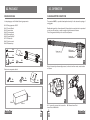
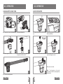
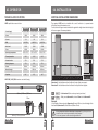
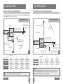
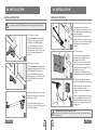
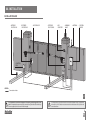
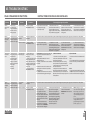
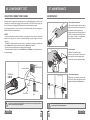
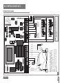
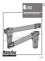
EN
LINCE
USER’S AND INSTALLER’S MANUAL
v2.2
REV. 07/2015
00. CONTENT
01. SAFETY INSTRUCTIONS
INDEX
STANDARDS TO FOLLOW
01. SAFETY INSTRUCTIONS
ATTENTION:
STANDARDS TO FOLLOW
01B
02.PACKAGE
INSIDE PACKAGE
02A
03. OPERATOR
CHANGE MOTOR DIRECTION
02B
MANUAL RELEASE
03B
TECHNICAL SPECIFICATIONS
04A
04. INSTALLATION
INSTALLATION DIMENSIONS
04B
INSTALLATION STEPS
06A
INSTALLATION MAP
07
05. TROUBLESHOOTING
FINAL CONSUMERS INSTRUCTIONS
08
INSTRUCTIONS FOR SPECIALIZED INSTALLERS
08
06. COMPONENTS TEST
CAPACITORS CONNECTION SCHEME
09A
07. MAINTENANCE
MAINTENANCE
• To ensure the safety of people, it is important that you read all the following
instructions.Incorrect installation or incorrect use of the product can cause physical
injury and material damage.
• Keep these instructions in a safe place for future reference.
• This product was designed and produced strictly for the use indicated in this manual.
Any other use, not expressly indicated here, could compromise the good condition/
operation of the product and/or be a source of danger.
• ELECTROCELOS S.A. is not responsible for the improper use of the product, or other
use than that for which it was designed.
• ELECTROCELOS S.A. is not responsible if safety standards were not taken into account
when installing the equipment, or for any deformation that may occur to it.
• ELECTROCELOS S.A. is not responsible for the safety and proper operation when
using components not sold by them.
• Do not make any modifications to the operator components and / or their accessories.
• Beffore installation unplug the automatism from the source of power.
• The installer must inform the client how to handle the product in case of emergency
and provide this manual to user.
• Keep remote controls away from children, to prevent the automated system from
being activated involuntarily.
• The customer shall not, under any circumstances, attempt to repair or tune the
operator .Must call qualified technician only.
• Connect the automatism to a 230V plug with ground wire.
• Operator for outdoor and indoor use.
09B
08. CONTROL BOARD MC2
CONNECTIONS SCHEME
10
2A
EN
2B
EN
02. PACKAGE
03. OPERATOR
INSIDE PACKAGE
CHANGE MOTOR DIRECTION
In the package you will find the following components:
The operator LINCE, is a product developed exclusively for the automatic opening of
swing gates.
01• 02 Swing operators LINCE
02• 01 Control Board
03• 02 transmitters
04• 02 Front supports
05• 02 Rear supports
06• 02 Capacitors 8μF
07• 01 Photocells
08• 01 User’s manual
09• 02 Release keys
Besides being pratical, safe and powerful, this product has a new function incorporated
so that you can transform a motor to apply on right leaves to left leaves.
This allows greater flexibility in the use of each operator.
09•
04•
05•
Middle part
Upper part
08•
Lower part
01•
06•
04
01
Motor disassembly and assembly process, in order to transform motor, must be done
as follows:
Electronic components the kit:
07•
03•
02•
02
210mm
280mm
05
810mm
03
3A
EN
01 • Loosen the screws that secure the
Lower Part to Middle Part
3B
EN
06
02 • Remove Lower Part
03. OPERATOR
03. OPERATOR
CHANGE MOTOR DIRECTION
UNLOCK OPERATOR
07
03 • Loosen the screws of the Middle Part
09
05 • Rotate Upper Part 180°
08
04 • Remove Middle Part
01 • Remove the plastic cap from the rear
end
Information engraved on the unlock shaft
D=Unlock || B=Lock
14
10
06 • Assemble operator by tightening all
components with the screws
13
12
15
02 • Insert Release key on the unlock shaft. 03 • Rotate key 180 ° in the direction indicated in the figure to unlock
04 • Operator unlocked.
16
11
07 • Full transformed operator
4A
EN
4B
EN
Note • To lock operator so it can work
automatically, must do it by turning the key
anticlockwise.
03. OPERATOR
04. INSTALLATION
TECHNICAL SPECIFICATIONS
VERTICAL INSTALLATION DIMENSIONS
LINCE specifications are as follow:
The operator LINCE must be installed with a small inclination , to prevent water
infiltration through the extension arm.
For this, the front support must be fixed to the gate with a height lower than the height
of the rear support. See example below:
LINCE300
LINCE400
LINCE600
AC 230V 50/60Hz
AC 230V 50/60Hz
AC 230V 50/60Hz
• Power
180W
180W
180W
• Current
1,3A
1,3A
1,3A
1400 RPM
1400 RPM
1400 RPM
• Noise level
<50dB
<50dB
<50dB
• Force
2300N
2300N
2300N
-25°C to 75°C
-25°C to 75°C
-25°C to 75°C
120°C
120°C
120°C
• Protection class
IP54
IP54
IP54
• Working frequence
25%
25%
25%
• Course
300mm
400mm
600mm
• Max leaf lenght
2500mm
3000mm
4000mm
8µF
8µF
8µF
• Power Supply
• RPM
• Operating temperatures
• Thermal protection
• Capacitor
A
B
A
B
18
LINCE 300 || 400 || 600 dimensions are the following:
Dimension A • Vertical distance from the floor to the top of the rear support .
Dimension B • Vertical distance from the floor to the top of the front support.
962mm || 1162mm || 1562mm
175mm
A
? mm
B
A-10mm
• Set dimension A (this can be any size of your choice).
• After you set dimension A, subtract 10mm to find dimensionB.
Example:
• If the height of the rear bracket (dimension A)is set at 600 mm, then the height of the
front bracket (dimension B) will be 590 mm (600mm-10mm).
159mm
647mm || 747mm || 947mm
104mm
It is very important that these dimensions are respected! Only this way can be assured the correct functioning and durability of the operators!
It is also very important to have a levelled ground/terrain!
17
5A
EN
5B
EN
04. INSTALLATION
04. INSTALLATION
VERTICAL INSTALLATION DIMENSIONS
HORIZONTAL INSTALLATION DIMENSIONS
On the Illustrated diagrams below and on the next page, are the horizontal dimensions
for the installation of the automated system.
INTERIOR OPENING
EXTERIOR OPENING
Axis of rotation of the
motor, on the front bracket
(EXTERIOR)
Opening mechanical stopper
Opening
direction
Closing mechanical
stopper
Axis of rotation of the gate
(center of the door hinge)
(EXTERIOR)
Y
W
Distance between the
centers of the holes on the
supports from operator
X
Axis of rotation of the
motor, on the rear support
Axis of rotation of the gate
(center of the door hinge)
Y
Opening
direction
(INTERIOR)
Opening mechanical stopper
• LINCE300
• LINCE400
• LINCE600
Axis of rotation of the
motor, on the rear support
19
X
Y
W
95º
120 a 180
120 a 180
895 a 900
• LINCE300
95º
120 a 180
120 a 180
1095 a 1100
120º
160 a 180
120 a 140
1095 a 1100
95º
120 a 350
120 a 200
1495 a 1500
120º
200 a 280
120 a 200
1495 a 1500
Opening angle
It is very important that these dimensions are respected! Only this way can be assured
the correct functioning and durability of the operators!
6A
EN
Axis of rotation of the motor,
on the front support
X
(INTERIOR)
Opening angle
Closing mechanical
stopper
W
Distance between the centers of the
holes on the supports from operator
X
Y
W
95º
120 a 180
120 a 180
595 a 600
• LINCE400
95º
160 a 200
120 a 180
695 a 700
• LINCE600
95º
160 a 300
120 a 280
900 a 905
Legend:
Dimension X - Horizontal distance between hinge axis of the door and the rear axle of the motor.
Dimension Y - Vertical distance between hinge axis of the door and the rear axle of the motor.
Dimension W - Distance between axis of the motor brackets.
6B
EN
20
04. INSTALLATION
04. INSTALLATION
INSTALLATION STEPS
INSTALLATION STEPS
04 • Install operator on the supports
Pay attention to installation dimensions mentioned on pages 04B, 05A and 05B!
01 • Fixing rear support
• The Rear support must be fixed to
the pillar or wall using dimensions
provided in the preceding pages.
It can be fixed using screws with
mechanical bushing or chemical
welding process, or one of your choice
since it provides an appropriate
support.
24
• The operator must be placed on
both supports the same time to avoid
leaving the operator suspended by only
one of the supports.
To make the task easier, you should
unlock the operator in order to be able
to stretch / retract arm easily (see page
03B),to get the correct position for
supports.
05 • Test movement
21
02 • Fixing front support
• The Front support should be fixed to
the gate, respecting height dimensions
and distance to the rear support.
This may be fixed by using screws,
welding process, or to choose another
long as it provides a secure proper
support.
25
• Install the pins removed earlier on
each place with a small amount of
lubricant for less friction.
• Move the door manually to see if the
door opens and closes uniformly and
correctly, without any irregular friction
during its entire travel;
This will ensure that operator is not
subjected to problems during operation.
06 • Connecting operator to control
board and configuring control devices.
22
03 • Remove caps and pins from motor
• Before installing motor, remove caps
and pins from motor.
26
• At the end of the installation, put
back plastic covers for a better visual
finish of the operator.
• With the operator installed, connect
it to control board for system
configuration (see control board user
manual).
Must also configure the desired control
devices (transmitters, wall switch, etc.)
and other additional components such
as antenna, warning light, key selector,
among others.
It is important to respect this installation order!
Otherwise, it is not possible to ensure correct installation and operators may not
work properly!
23
7A
EN
7B
EN
04. INSTALLATION
INSTALLATION MAP
• INTERIOR
PHOTOCELLS
• EXTERIOR
PHOTOCELLS
• MOTOR LINCE
• EXTERIOR
PHOTOCELLS
• KEY
SELECTOR
• WARNING
LAMP
• ANTENNA
• CONTROL
BOARD
• JUNCTION
BOX
LEGEND:
• Connection cables
27
It is important to use mechanical stoppers in the opening and closing position of the
gate.If not respected, components of the automation may suffer efforts for which they
were not prepared, and as a result will be damaged.
It is important to use junction boxes for connections between motors, components
and control unit. All cables must enter and exit on the bottom of the junction and
control board box.
8
EN
05. TROUBLESHOOTING
INSTRUCTIONS FOR SPECIALIZED INSTALLERS
FINAL CONSUMERS INSTRUCTIONS
Anomaly
Procedure
Behavior
• Still not working
Procedure II
• Motor
doesn't work
at all
•Make sure you
have 230V power
supply connected to
operator and if it is
working properly.
• Motor
doesn’t move
but makes
noise
• Unlock motor and
• Encountered
• Consult an experienced
move gate by hand to problems?
gate expert
check for mechanical
problems on the gate. •Gate moves easily? • Consult a qualified
MOTORLINE technician.
• Motor opens • Unlock motor and
• Gate opened but
but doesn’t
move gate by hand to didn’t close again.
close
closed position.
Lock motor(s) again
and turn off power
supply for 5 seconds.
Reconnect it and send
order to open
gate using
transmitter.
• Motor
doesn’t make
complete
route
• Consult a qualified
MOTORLINE technician.
1 • Check if there is any
obstacle in front of the
photocells;
2 • Check if any of the control
devices (key selector, push
button, video intercom, etc.)
of the gate are jammed and
sending permanent signal to
control unit;
3 • Consult a qualified
MOTORLINE technician.
• Unlock motor and
• Encountered
• Consult an experienced
move gate by hand to problems?
gate expert
check for mechanical
problems on the gate. • Gate moves easily? • Consult a qualified
MOTORLINE technician.
Discovering the origin of the problem
1 • Open control box and check if
it has 230V power supply;
2 • Check input fuses;
3 • Disconnect motors from
control board and test them by
connecting directly to power
supply in order to find out if they
have problems (see page 09A).
4 • If the motors work, the
problem is on the control board.
Pull it out and send it to our
MOTORLINE technical services
for diagnosis;
5 • If the motors doesn’t work,
remove them from installation
site and send to our MOTORLINE
technical services for diagnosis.
1 • Check all motion axis and associated motion systems related with gate and operators (pins, hinges, etc.) to find out what is the problem.
1 • Check capacitors, testing
operator with new capacitors;
2 • If capacitors are not the
problem, disconnect motors
from control board and test them
by connecting directly to power
supply in order to find out if they
have problems (see page 09A).
All MOTORLINE control boards have LEDs that
easily allow to conclude which devices are
with anomalies.
All safety devices LEDs (DS) in normal
situations remain On.
All "START" circuits LEDs in normal situations
remain Off.
If LEDs devices are not all On, there is some
security systems malfunction (photocells,
safety edges), etc.
If "START" circuits LEDs are turn On, there is
a control device sending permanent signal.
3 • If the motors work, the
problem is from control board.
Pull it out and send it to our
MOTORLINE technical services
for diagnosis;
4 • If the motors doesn’t work,
remove them from installation
site and send to our MOTORLINE
technical services for diagnosis.
A) SECURITY SYSTEMS:
B) START SYSTEMS:
1 • Close with a shunt all safety systems
on the control board (check manual of the
control board in question).
If the automated system starts working
normally check for the problematic device.
2 • Remove one shunt at a time until you find
the malfunction device .
3 • Replace it for a functional device and
check if the operator works correctly with
all the other devices. If you find another one
defective, follow the same steps until you find
all the problems.
1 • Disconnect all wires from START terminal
input.
2 • If the LED turned Off, try reconnecting one
device at a time until you find the defective
device.
NOTE:
n case procedures described in sections A)
and B) don’t result, remove control board and
send to our technical services for diagnosis.
1 • Check all motion axis and associated motion systems related with gate and operators (pins, hinges, etc.) to find out what is the problem.
1 • Check capacitors, testing
with new capacitors;
2 • If capacitors are not the
problem, disconnect motors
from control board and test them
by connecting directly to power
supply in order to find out if they
are faulty;
3 • If the motors doesn’t work,
remove them from installation
site and send to our MOTORLINE
technical services for diagnosis.
4 • If motors work well and move
gate at full force during the
entire course, the problem is
from controller. Set force using
trimmer on the board. Make a
new working time programming ,
giving suffient time for opening
and closing with appropriate
force (see manual of the
controller in question).
5 • If this doesn’t work, remove
control unit and send it to
MOTORLINE technical services
services.
NOTE: Setting force of the
controller should be sufficient to
make the gate open and close
without stopping, but should
stop with a little effort from a
person.
In case of safety systems failure,
the gate shall never cause
physical damaged to obstacles
(vehicles, people, etc.).
9
EN
06. COMPONENTS TEST
07. MAINTENANCE
CAPACITORS CONNECTION SCHEME
MAINTENANCE
To detect which components have problems on an automated system, sometimes it is
necessary to conduct tests using a direct connection to a 230V AC power supply. For
this it is necessary to merge a 8μF capacitor to make the operator to work.
In the diagram below is shown how this link should be made and how to merge the
different wires of the components.
• Clean stainless steel arm
• With a cloth soaked in lubricant spray,
wipe any residue that accumulates on
the operator’s stainless steel arm.
• Apply a small amount of spray lubricant
on the arm and using a dry cloth remove
the excess, leaving a homogeneous
layer of lubricant over the arm.
NOTES:
• To perform these tests you don’t need to remove operator from where it is installed,
because this way you can know if connected directly to power supply it will work
correctly.
• The order of wiring capacitor to motor wires is not important, as long you connect one
wire to Brown wire of motor and the other one to Black wire of motor;
• Common wire should always be connected to power supply.
• To reverse motor direction, just replace Black wire with Brown wire of the operator on
the power supply.
Common (Blue)
OPERATOR
LINCE
29
• Lubricate pins
• Remove front and rear caps
• Place a small amount of lubricant on
the holes that contains support pins.
• Install caps on the respective holders.
230V
POWER SUPPLY
30
• Check motor supports
Black
•Make sure that supports remain well
fixed on the pillars and gate to ensure
proper functioning of the equipment.vz
Brown
Earth wire
CAPACITOR
8µF
31
28
All tests must be performed by qualified personnel due to serious danger associated
with the misuse of electrical systems!
These maintenance measures must be applied every year in order to insure proper
functioning of the automated system.
10A
10B
EN
EN
2
N
110V
Earth wire
8
µ
4
LAMP
3
Light Bulb
L N
L
110V
1
6
7
MOTORE 1
AP COM CH
5
9 10
MOTORE 2
AP COM CH
8
Black
Motor 2
Black
Blue
Brown
NOTE • If any one of the motors moves in
the wrong way, just switch the brown and
black cables of that motor to change the
direction.
- Motor 1 starts opening before Motor 2
- Motor 2 starts closing before Motor 1
- It must be applied an 8µ capacitor in
each motor, on the opening and closing
wires as explained above.
PL
3
8
µ
Brown
Motor 1
2
Earth wire
1
V
1
2
4
PUL
5
6
8
DS2
-
+
~ ~
5
NC
3
4
5
K2
Close the circuit with bridge (shunt)
when the photocells circuit is not
being used!
~ ~
+
-
-
+
0V 12/24V COM
~ ~
4
COM NC NO
1
K1
10V 12/24V
2
2
NC
3
K2
COM NC NO
Interior Photocells
~ ~
+
-
2
0V 12/24V COM
1
10V 12/24V
2
K1
Antenna
9 10 11 12
Pedestrian
Opening
(1 leaf)
PED DS1
7
Exterior Photocells
Complete
Opening
(2 leaves)
Lock
SERR.
3
PUL PED DS1 DS2
- Force +
T.RIT.ANT
T. PAUSA
T.MOT.PED
T.MOTOR
INB.CMD.AP
CODE PED
CODE
AUT/P-P
08. CONTROL BOARD MC2
CONNECTIONS SCHEME
Blue
32
11
EN