1
COMPACT-LINE Programming manual ER23K Installationmanual ER23K Inverter EN 6 1 8 0 0 -3 Line voltage: Line voltage: Line voltage Line voltage 02/2010 1 ~ 200 - 240 V 1(3)~ 200 - 240 V 3 ~ 380 - 500 V 3 ~ 525 - 600 V - Output: 3~ 0 - 240 V Output: 3~ 0 - 240 V Output: 3~ 0 - 500 V Output: 3~ 0 - 600 V Power: 0,18Power: 0,18Power: 0,37Power: 0,75- 2,2 15,0 15,0 15,0 kW kW kW kW Contents Important information __________________________________________________________________________________________ 4 Before you begin______________________________________________________________________________________________ 5 Documentation structure________________________________________________________________________________________ 7 Steps for setting up the drive ____________________________________________________________________________________ 8 Setup - Preliminary Recommendations ____________________________________________________________________________ 9 Factory configuration _________________________________________________________________________________________ 10 Basic functions ______________________________________________________________________________________________ 11 Remote display terminal option, ER22 ____________________________________________________________________________ 13 Remote graphic display terminal option, ER40______________________________________________________________________ 14 Remote display terminal option, ER12 ____________________________________________________________________________ 18 Structure of the parameter tables ________________________________________________________________________________ 19 Compatibility of functions ______________________________________________________________________________________ 20 List of functions that can be assigned to inputs/outputs _______________________________________________________________ 22 List of functions that can be assigned to the Network and Modbus control word bits ________________________________________ 24 Checklist ___________________________________________________________________________________________________ 25 Programming _______________________________________________________________________________________________ 26 [SPEED REFERENCE] (rEF-) menu _____________________________________________________________________________ 30 [SETTINGS] (SEt-) menu ______________________________________________________________________________________ 31 [MOTOR CONTROL] (drC-) menu _______________________________________________________________________________ 39 [INPUTS / OUTPUTS CFG] (I-O-) menu __________________________________________________________________________ 45 [COMMAND] (CtL-) menu______________________________________________________________________________________ 48 [COMMAND] (CtL-) menu______________________________________________________________________________________ 59 [APPLICATION FUNCT.] menu (FUn-) ___________________________________________________________________________ 60 [FAULT MANAGEMENT] (FLt-) menu ____________________________________________________________________________ 86 [COMMUNICATION] (COM-) menu ______________________________________________________________________________ 92 [MONITORING] (SUP-) menu __________________________________________________________________________________ 94 Migration ER22K/P - ER23K____________________________________________________________________________________ 99 Diagnostics and troubleshooting________________________________________________________________________________ 100 Index of functions ___________________________________________________________________________________________ 105 Index of parameter codes and customer settings___________________________________________________________________ 106 Wiring / evaluation of PTC ___________________________________________________________________________________ 120 3 Important information NOTICE Read these instructions carefully, and look at the equipment to become familiar with the device before trying to install, operate, or maintain it. The following special messages may appear throughout this documentation or on the equipment to warn of potential hazards or to call attention to information that clarifies or simplifies a procedure. The addition of this symbol to a Danger or Warning safety label indicates that an electrical hazard exists, which will result in personal injury if the instructions are not followed. This is the safety alert symbol. It is used to alert you to potential personal injury hazards. Obey all safety messages that follow this symbol to avoid possible injury or death. DANGER DANGER indicates an imminently hazardous situation which, if not avoided, will result in death, serious injury or equipment damage. WARNING WARNING indicates a potentially hazardous situation which, if not avoided, can result in death, serious injury or equipment damage. CAUTION CAUTION indicates a potentially hazardous situation which, if not avoided, can result in injury or equipment damage. CAUTION CAUTION, used without the safety alert symbol, indicates a potentially hazardous situation which, if not avoided, can result in equipment damage. PLEASE NOTE The word "drive" as used in this manual refers to the "controller portion" of the adjustable speed drive as defined by NEC. Electrical equipment should be installed, operated, serviced, and maintained only by qualified personnel. No responsibility is assumed by BLEMO for any consequences arising out of the use of this documentation. © 2009 BLEMO. All rights reserved. 4 Before you begin Read and understand these instructions before performing any procedure with this drive. DANGER HAZARD OF ELECTRIC SHOCK, EXPLOSION, OR ARC FLASH • Read and understand this manual before installing or operating the ER23K drive. Installation, adjustment, repair, and maintenance must be performed by qualified personnel. • The user is responsible for compliance with all international and national electrical code requirements with respect to grounding of all equipment. • Many parts of this drive, including the printed circuit boards, operate at the line voltage. DO NOT TOUCH. Use only electrically insulated tools. • DO NOT touch unshielded components or terminal strip screw connections with voltage present. • DO NOT short across terminals PA/+ and PC/– or across the DC bus capacitors. • Before repairing the variable speed drive: - Disconnect all power, including external control power that may be present. - Place a “DO NOT TURN ON” label on all power disconnects. - Lock all power disconnects in the open position. - WAIT 15 MINUTES to allow the DC bus capacitors to discharge. - Measure the voltage of the DC bus between the PA/+ and PC/– terminals to ensure that the voltage is less than 42 Vdc. - If the DC bus capacitors do not discharge completely, contact your local BLEMO representative. Do not repair or operate the drive • Install and close all covers before applying power or starting and stopping the drive. Failure to follow these instructions will result in death or serious injury. DANGER UNINTENDED EQUIPMENT OPERATION • Read and understand this manual before installing or operating the ER23K drive. • Any changes made to the parameter settings must be performed by qualified personnel. Failure to follow these instructions will result in death or serious injury. WARNING DAMAGED EQUIPMENT Do not install or operate any drive that appears damaged. Failure to follow these instructions can result in death, serious injury, or equipment damage. 5 Before you begin WARNING LOSS OF CONTROL • The designer of any wiring diagram must take account of potential control channel failure modes and, for certain critical control functions, incorporate a way of achieving a safe state during and after a channel failure. Examples of critical control functions are emergency stop and overtravel stop. • Separate or redundant control channels must be provided for critical control functions. • System control paths may include communication links. Consideration must be given to the implications of unanticipated transmission delays or failures of the link. a Failure to follow these instructions can result in death, serious injury, or equipment damage. a) For additional information, refer to NEMA ICS 1.1 (latest edition), "Safety Guidelines for the Application, Installation, and Maintenance of Solid State Control" and to NEMA ICS 7.1 (latest edition), "Safety Standards for Construction and Guide for Selection, Installation and Operation of Adjustable-Speed Drive Systems". 6 Documentation structure The following ER23K technical documents are available on the BLEMO website (www.blemo.com). Installation Manual This manual describes how to install and connect the drive. User manual This manual describes the functions and parameters of the drive's terminals and how to use them. Simplified manual This manual is a simplified version of the installation and programming manuals. It is supplied with the drive. Quick Start This document describes how to connect and configure the drive so that the motor can be started both quickly and easily for basic applications. This document is supplied with the drive. Manuals for Modbus, CANopen, etc. These manuals describe the installation process, the bus or network connections, signaling, diagnostics and the configuration of parameters specific to communication. They also describe the communication services of the protocols. 7 Steps for setting up the drive INSTALLATION 1. Please refer to the Installation Manual. PROGRAMMING 2. Apply input power to the drive, but do not give a run command. 3. Configure: • The Tips: • Before beginning programming, complete the customer setting tables, page 106. • Use the [Restore config.] (FCS) parameter, page 44, to return to the factory settings at any time. • To locate the description of a function quickly, use the index of functions on page 105. • Before configuring a function, read carefully the "Function compatibility" section on pages 20 and 21. • Note: The following operations must be performed for optimum drive performance in terms of accuracy and response time: - Enter the values indicated on the (motor) rating plate in the [MOTOR CONTROL] (drC-) menu, page 39. - Perform auto-tuning with the motor cold and connected using the [Auto-tuning] (tun) parameter, page 41. - Adjust the [FreqLoopGain] (FLG) parameter, page 32 and the [Fr.Loop.Stab] (StA) parameter, page 33. nominal frequency of the motor [Standard mot. freq] (bFr) page 39 if this is not 50 Hz, • The motor parameters in the [MOTOR CONTROL] (drC-) menu, page 39, only if the factory configuration of the drive is not suitable, • The application functions in the [INPUTS / OUTPUTS CFG] (I-O-) menu, page 45, the [COMMAND] (CtL-) menu, page 48, and the [APPLICATION FUNCT.] (FUn-) menu, page 60, only if the factory configuration of the drive is not suitable. 4. In the [SETTINGS] (SEt-) menu, adjust the following parameters: • [Acceleration] (ACC), page 31 and [Deceleration], (dEC) page 31, • [Low speed] (LSP), page 32 and [High speed] (HSP), page 32, • [Mot. therm. current] (ItH), page 32. 5. Start the drive. 8 Setup - Preliminary Recommendations Before powering up the drive DANGER UNINTENDED EQUIPMENT OPERATION Make sure that all logic inputs are inactive to avoid any unintended operation. Failure to follow these instructions will result in death or serious injury. Before configuring the drive DANGER UNINTENDED EQUIPMENT OPERATION • Read and understand this manual before installing or operating the ER23K drive. • Any changes made to the parameter settings must be performed by qualified personnel. • Make sure that all logic inputs are inactive to avoid any unintended operation when parameters are being changed. Failure to follow these instructions will result in death or serious injury. Start-up Note: When factory settings apply and during power-up/manual reset or after a stop command, the motor can only be powered once the "forward", "reverse" and "DC injection stop" commands have been reset. If they have not been reset, the drive will display [Freewheel stop] (nSt) but will not start. If the automatic restart function has been configured ([Automatic restart] (Atr) parameter in the [FAULT MANAGEMENT] (FLt-) menu, page 86), these commands are taken into account without a reset (to zero) being necessary. Line contactor CAUTION RISK OF DAMAGE TO DRIVE • Frequent use of the contactor will cause premature ageing of the filter capacitors. • Do not have cycle times less than 60 seconds. Failure to follow these instructions can result in equipment damage. Using a motor with a lower rating or dispensing with a motor altogether • With the factory settings, motor output phase loss detection is active ([Output Phase Loss] (OPL) = [YES] (YES), page 89). To avoid having to use a motor with the same rating as the drive when testing the drive or during a maintenance phase, deactivate motor output phase loss detection ([Output Phase Loss] (OPL) = [No] (nO)). This can prove particularly useful if very powerful drives are being used. • Set the [U/F mot 1 selected] (UFt) parameter, page 42, on [Cst. torque] (L) in the [MOTOR CONTROL] (drC-) menu. CAUTION RISK OF DAMAGE TO MOTOR Motor thermal protection will not be provided by the drive if the motor 's nominal current is 20% lower than that of the drive. Find an alternative source of thermal protection. Failure to follow these instructions can result in equipment damage. 9 Factory configuration Factory settings The ER23K is factory-set for the most common operating conditions: • Display: drive ready [Ready] (rdY) with motor stopped, and motor frequency with motor running. • The LI5 and LI6 and logic inputs, AI3 analog input, AOC analog output, and R2 relay are unaffected. • Stop mode when fault detected: freewheel Code Description Value Page bFr [Standard mot. freq] [50Hz IEC] 39 tCC [2/3 wire control] [2 wire] (2C): 2-wire control 29 UFt [U/F mot 1 selected] [SVC] (n): Sensorless flux vector control for constant torque applications 42 ACC DEC [Acceleration] [Deceleration] 3.00 seconds 61 LSP [Low speed] 0 Hz 32 HSP [High speed] 50 Hz 32 ItH [Mot. therm. current] Nominal motor current (value depending on drive rating) 32 SdC1 [Auto DC inj. level 1] 0.7 x nominal drive current, for 0.5 seconds 33 SFr [Switching freq.] 4 kHz 38 rrS [Reverse assign.] [LI2] (LI2): Logic input LI2 46 PS2 [2 preset speeds] [LI3] (LI3): Logic input LI3 69 PS4 [4 preset speeds] [LI4] (LI4): Logic input LI4 69 Fr1 [Ref.1 channel] [AI1] (AI1) - Analog input AI1 28 SA2 [Summing ref. 2] [AI2] (AI2) - Analog input AI2 67 r1 [R1 Assignment] [No drive flt] (FLt): The contact opens when a fault is detected or when the drive has been switched off 47 brA [Dec ramp adapt.] [Yes] (YES): Function active (automatic adaptation of deceleration ramp) 62 Atr [Automatic restart] [No] (nO): Function inactive 86 Stt [Type of stop] [Ramp stop] (rMP): On ramp 63 CFG [Macro configuration] [Factory set.] (Std) (1) 43 Check whether the values above are compatible with the application. If necessary, the drive can be used without changing the settings. (1) If you want to keep the drive's presettings to a minimum, select the macro configuration [Macro configuration] (CFG) = [Start/stop] (StS) followed by [Restore config.] (FCS) = [Config. CFG] (InI) (page 44). The [Start/stop] (StS) macro configuration is the same as the factory configuration, apart from the I/O assignment: • Logic inputs: - LI1, LI2 (reversing): 2-wire transition detection control, LI1 = run forward, LI2 = run reverse. - LI3 to LI6: Inactive (not assigned). • Analog inputs: - AI1: Speed reference 0-10 V. - AI2, AI3: Inactive (not assigned). • Relay R1: The contact opens in the event of a detected fault (or drive off). • Relay R2: Inactive (not assigned). • Analog output AOC: 0-20 mA, inactive (not assigned). 10 Basic functions Drive thermal protection Functions: Thermal protection by PTC probe fitted on the heatsink or integrated in the power module. Indirect protection of the drive against overloads by tripping in the event of an overcurrent. Typical tripping values: - Motor current = 185% of nominal drive current: 2 seconds - Motor current = 150% of nominal drive current: 60 seconds Time (seconds) Motor current/In drive Drive ventilation The fan starts up when the drive is powered up then shuts down after 10 seconds if a run command has not been received. The fan is powered automatically when the drive is unlocked (direction of operation + reference). It is powered down a few seconds after the drive is locked (motor speed < 0.2 Hz and injection braking completed). 11 Basic functions Motor thermal protection Function: Thermal protection by calculating the I2t. The protection takes account of self-cooled motors. Tripping time t in seconds Motor current/ [Mot. therm. current] (ItH) CAUTION RISK OF DAMAGE TO MOTOR External protection against overloads is required under the following circumstances: • When the product is being switched on again, as there is no memory to record the motor thermal state • When supplying more than one motor • When supplying motors with ratings less than 0.2 times the nominal drive current • When using motor switching Failure to follow these instructions can result in equipment damage. 12 Remote display terminal option, ER23K This terminal is a local control unit which can be mounted on the door of the wall-mounted or floor-standing enclosure. It has a cable with connectors, which is connected to the drive serial link (see the manual supplied with the terminal). Its display capabilities are practically identical to those of the ER23K. With this terminal, however, up and down arrows are used for navigation rather than a jog dial. There is also an access locking switch for the menus. There are three buttons for controlling the drive (1): • FWD/REV: Reversal of the direction of rotation • RUN: Motor run command • STOP/RESET: Motor stop command or reset Pressing the button a first time stops the motor, and if DC injection standstill braking is configured, pressing it a second time stops this braking. View of the front panel:: View of the rear panel : 4-character display Connector Access locking switch: • Position: • Position: • Position: [MONITORING] (SUP-) and [SPEED REFERENCE] (rEF-) menus can be accessed. [SETTINGS] (SEt-), [MONITORING] (SUP-) and [SPEED REFERENCE] (rEF-) can be accessed. All menus can be accessed Note: Protection via customer confidential code has priority over the switch. Note: • The remote terminal access locking switch also locks access by the drive keys. • When the remote display terminal is disconnected, any locking remains active for the drive keys. • The remote display terminal will only be active if the [Modbus baud rate] (tbr) parameter in the [COMMUNICATION] (COM-) menu, page 92, still has its factory setting: [19.2 Kbps] (19.2). (1) To activate the buttons on the remote display terminal, you first have to configure [HMI command] (LCC) = [Yes] (YES), page 58. Saving and loading configurations Up to four complete configurations for ER23K drives without an option card can be stored on the remote display terminal. These configurations can be saved, transported and transferred from one drive to another of the same rating. 4 different operations for the same device can also be stored on the terminal. See the [Saving config.] (SCS) and [Restore config.] (FCS) parameters in the [MOTOR CONTROL] (drC-) menu, pages 43 and 44, the [INPUTS / OUTPUTS CFG] (I-O-) menu, pages 47 and 47, the [COMMAND] (CtL-) menu, pages 59 and 59, and the [APPLICATION FUNCT.] (FUn-) menu, pages 85 and 85. To transfer a configuration between an ER23K and an ER22, follow the procedure on page 85. 13 Remote graphic display terminal option, ER40 Description of the terminal Thanks to the screen size of this graphic display terminal, which works with FLASH V1.1IE19 or higher and is part of the ER40, it is possible to display more detailed information than can be shown on an on-board display. It is connected in the same way as the ER23K remote display terminal. 1 Graphic display 2 Function keys: F1: CODE F2, F3: not used F4: MODE 3 Button to stop/reset 7 ESC button:cancels a value, a parameter or a menu to return to the previous selection 4 Run button 6 Button for reversing the direction of rotation of the motor 5 Navigation button: • Press (ENT): - To save the current value - To enter the selected menu or parameter • Turn CW/CCW: - To increase or decrease a value - To go to the next or previous line - To increase or decrease the reference if control via the display terminal is activated Note: Keys 3, 4, 5 and 6 can be used to control the drive directly, if control via the terminal is activated. To activate the buttons on the remote display terminal, you first have to configure [HMI command] (LCC) = [Yes] (YES), page 58. 14 Remote graphic display terminal option, ER40 (continued) Powering up the graphic display terminal for the first time When powering up the graphic display terminal for the first time, the user has to select the required language. LANGUAGE English Français Deutsch Espanol Italiano Display after the graphic display terminal has been powered up for the first time. Select the language and press ENT. Chinese Russian Turkish The drive's rating details will now appear. ER23K 1.5kW/2HP 200/240V MAIN MENU DRIVE MENU LANGUAGE The [MAIN MENU] follows automatically. 3 seconds or ENT DRIVE MENU SPEED REFERENCE SETTINGS MOTOR CONTROL INPUTS / OUTPUTS CFG COMMAND Code APPLICATION FUNCT. FAULT MANAGEMENT COMMUNICATION Automatically switches to the [DRIVE MENU] menu after 3 seconds. Select the menu and press ENT. Mode 15 Remote graphic display terminal option, ER40 (continued) Powering up the drive for the first time When powering up the drive for the first time, the user immediately accesses the 3 parameters below: [Standard mot. freq] (bFr), [Ref.1 channel] (Fr1), and [2/3 wire control] (tCC), page 29. . Display after the drive has been powered up for the first time. ER23K 1.5kW/2HP 200/240V MAIN MENU DRIVE MENU LANGUAGE The [MAIN MENU] follows automatically. 3 seconds DRIVE MENU Standard mot. freq 2/3 wire control Ref.1 channel SPEED REFERENCE SETTINGS Automatically switches to the [DRIVE MENU] menu after 3 seconds. Select the menu and press ENT. MOTOR CONTROL INPUTS / OUTPUTS CFG COMMAND APPLICATION FUNCT. FAULT MANAGEMENT COMMUNICATION ESC DRIVE MENU The word "Ready" appears on the graphic display terminal if you press the ESC key when in the [DRIVE MENU]. Ready Code 16 Mode Remote graphic display terminal option, ER40 (continued) Subsequent power-ups Display after powering up. ER23K 1.5kW/2HP 200/240V MAIN MENU DRIVE MENU LANGUAGE The [MAIN MENU] follows automatically. 3 seconds DRIVE MENU SPEED REFERENCE SETTINGS MOTOR CONTROL INPUTS / OUTPUTS CFG COMMAND Code APPLICATION FUNCT. FAULT MANAGEMENT COMMUNICATION Automatically switches to the [DRIVE MENU] menu after 3 seconds. Select the menu and press ENT. Mode ESC DRIVE MENU The word "Ready" appears on the graphic display terminal if you press the ESC key when in the [DRIVE MENU]. Ready Code Mode 17 Remote display terminal option, ER12 Description of the terminal This terminal is a local control unit which can be mounted on the door of the wall-mounted or floor-standing enclosure. It has a cable with connectors, which is connected to the drive serial link (see the manual supplied with the terminal). Its display capabilities are practically identical to those of the ER23. With this terminal, up and down arrows are used for navigation rather than a jog dial. 1 Graphic display 2 MODE button (1): If [SPEED REFERENCE] (rEF-) is displayed, this will take you to the [SETTINGS] (SEt-) menu. If not, it will take you to the [SPEED REFERENCE] (rEF-) menu. 3 ESC button Used to quit a menu/parameter or remove the currently displayed value in order to revert to the previous value retained in the memory 4 RUN button Executes the function assuming it has been configured 5 Navigation keys 6 ENT button Used to save the current value or access the selected menu/parameter 7 STOP button Used to stop the motor and perform a reset 8 Button for reversing the direction of rotation of the motor (1) If the drive is locked by a code ([PIN code 1] (COd), page 97), pressing the Mode key enables you to switch from the [MONITORING] (SUP-) menu to the [SPEED REFERENCE] (rEF-) menu and vice versa. To activate the buttons on the remote display terminal, you first have to configure [HMI command] (LCC) = [Yes] (YES), page 58. 18 Structure of the parameter tables The parameter tables contained in the descriptions of the various menus are organized as follows. Example : 5 APPLICATION FUNCT.] menu (Fun-) 6 1 Code 2 Name/Description Adjustment range Factory setting • [PI regulator] PI- Note: The "PI regulator" function is incompatible with several functions (see page 20). It can only be configured if these functions are unassigned, in particular the summing inputs (set [Summing ref. 2] (SA2) to [No] (nO), page 67) and the preset speeds (set [2 preset speeds] (PS2) and [4 preset speeds] (PS4) to [No] (nO), page 69) which will have been assigned as part of the factory settings. 3 4 PIF no AI1 A12 A13 • [PID feedback ass.] - [Non] (nO): not assigned - [AI1] (AI1): analog input AI1 - [AI2] (AI2): analog input AI2 - [AI3] (AI3): analog input AI3 7 [Non] (nO) 8 1. Name of menu on 4-digit 7-segment display 5. Name of menu on ER40 graphic display terminal 2. Submenu code on 4-digit 7-segment display 6. Name of submenu on ER40 graphic display terminal 3. Parameter code on 4-digit 7-segment display 7. Name of parameter on ER40 graphic display terminal 4. Parameter value on 4-digit 7-segment display 8. Value of parameter on ER40 graphic display terminal 19 Compatibility of functions Incompatible functions The following functions will be inaccessible or deactivated in the cases described below: Automatic restart This is only possible for the 2-wire level control type ([2/3 wire control] (tCC) = [2 wire] (2C) and [2 wire type] (tCt) = [Level] (LEL) or [Fwd priority] (PFO)). Catch on the fly This is only possible for the 2-wire level control type ([2/3 wire control] (tCC) = [2 wire] (2C) and [2 wire type] (tCt) = [Level] (LEL) or [Fwd priority] (PFO)). This function is locked if automatic standstill injection has been configured as DC ([Auto DC injection] (AdC) = [Continuous] (Ct)). Function compatibility table The choice of application functions may be limited by the number of I/O and by the fact that some functions are incompatible with one another. Functions which are not listed in this table are compatible. If there is an incompatibility between functions, the first function configured will prevent the others being configured. Management of limit switches Freewheel stop Fast stop DC injection stop Brake control Jog operation Management of limit switches PI regulator +/- speed (1) Preset speeds (factory setting) Summing inputs (factory setting) +/- speed (1) Summing inputs (factory setting) To configure a function, first check that functions which are incompatible with it are unassigned, especially those which are assigned in the factory settings. Preset speeds (factory setting) f PI regulator Jog operation f Brake control f DC injection stop Fast stop Freewheel stop f f (1) Excluding special application with reference channel [Ref.2 channel] (Fr2) (see diagrams 51 and 53) Incompatible functions Compatible functions Not applicable Priority functions (functions which cannot be active at the same time): The function marked with the arrow takes priority over the other. f Stop functions take priority over run commands. Speed references via logic command take priority over analog references. 20 Compatibility of functions Logic and analog input application functions Each of the functions on the following pages can be assigned to one of the inputs. A single input can activate several functions at the same time (reverse and 2nd ramp for example). The user must therefore ensure that these functions can be used at the same time. The [MONITORING] (SUP-) menu ([[LOGIC INPUT CONF.]] (LIA-) parameter, page 98, and [[ANALOG INPUTS IMAGE]] (AIA-) parameter, page 98) can be used to display the functions assigned to each input in order to check their compatibility. Before assigning a reference, command or function to a logic or analog input, the user must check that this input has not already been assigned in the factory settings and that no other input has been assigned to an incompatible or unwanted function. • Example of incompatible function to be unassigned: In order to use the "+speed/-speed" function, the preset speeds and summing input 2 must first be unassigned. The table below lists the factory-set input assignments and the procedure for unassigning them. Assigned input Function Code To unassign, set to: Page LI2 Run reverse rrS nO 46 LI3 2 preset speeds PS2 nO 69 LI4 4 preset speeds PS4 nO 69 AI1 Reference 1 Fr1 Anything but AI1 56 LI1 Run forward tCC 2C or 3C 45 AI2 Summing input 2 SA2 nO 67 21 List of functions that can be assigned to inputs/outputs Logic inputs Page Code Not assigned - - LI5 - LI6 Run forward - - LI1 2 preset speeds 69 PS2 LI3 4 preset speeds 69 PS4 LI4 8 preset speeds 69 PS8 16 preset speeds 70 PS16 2 preset PI references 77 Pr2 4 preset PI references 78 Pr4 + speed 74 USP - speed 74 dSP Jog operation 72 JOG Ramp switching 62 rPS 2nd current limit switching 81 LC2 Fast stop via logic input 63 FSt DC injection via logic input 63 dCI Freewheel stop via logic input 64 nSt Run reverse 46 rrS External fault 88 EtF RESET 87 rSF Forced local mode 93 FLO Reference switching 57 rFC Control channel switching 58 CCS Motor switching 82 CHP Forward limit switch 84 LAF Reverse limit switch 84 LAr Fault inhibition 91 InH Analog inputs Page Code Not assigned - - AI3 Reference 1 56 Fr1 AI1 Reference 2 56 Fr2 Summing input 2 67 SA2 Summing input 3 67 SA3 PI regulator feedback 77 PIF 22 Factory setting LI2 Factory setting AI2 List of functions that can be assigned to inputs/outputs Analog/logic output Page Code Not assigned - - Motor current 46 OCr Motor frequency 46 OFr Motor torque 46 Otr Power supplied by the drive 46 OPr Drive detected fault (logic data) 46 FLt Drive running (logic data) 46 rUn Frequency threshold reached (logic data) 46 FtA High speed (HSP) reached (logic data) 46 FLA Current threshold reached (logic data) 46 CtA Frequency reference reached (logic data) 46 SrA Motor thermal threshold reached (logic data) 46 tSA Brake sequence (logic data) 46 bLC Page Code Relay Factory setting AOC/AOV Factory setting Not assigned - - R2 Detected fault 47 FLt R1 Drive running 47 rUn Frequency threshold reached 47 FtA High speed (HSP) reached 47 FLA Current threshold reached 47 CtA Frequency reference reached 47 SrA Motor thermal threshold reached 47 tSA Brake sequence 47 bLC Copy of the logic input 47 LI1 to LI6 23 List of functions that can be assigned to the Network and Modbus control word bits Bits 11 to 15 of the control word Page Code 2 preset speeds 69 PS2 4 preset speeds 69 PS4 8 preset speeds 69 PS8 16 preset speeds 70 PS16 2 preset PI references 77 Pr2 4 preset PI references 78 Pr4 Ramp switching 62 rPS 2nd current limit switching 81 LC2 Fast stop via logic input 63 FSt DC injection 63 dCI External fault 88 EtF Reference switching 57 rFC Control channel switching 58 CCS Motor switching 82 CHP 24 Checklist Carefully read the information contained in the programming, installation and simplified manuals, as well as the information in the catalog. Before starting to use the drive, please check the following points relating to mechanical and electrical installations. For the full range of documentation, please visit www.blemo.com. 1. Mechanical installation (see the simplified and installation manuals) • For details of the different installation types and recommendations concerning ambient temperature, please refer to the installation instructions in the simplified or installation manuals. • Install the drive vertically in accordance with the specifications. Please refer to the installation instructions in the simplified or installation manuals. • When using the drive, both the environmental conditions defined under standard 60721-3-3 and the levels defined in the catalog must be respected. • Install the required options for your application. Refer to the catalog for details. 2. Electrical installation (see the simplified and installation manuals) • Ground the drive. See the sections on how to ground equipment in the simplified and installation manuals. • Make sure the input supply voltage matches the nominal drive voltage and connect the line supply in accordance with the simplified and installation manuals. • Make sure you use appropriate input line fuses and circuit breakers. See the simplified and installation manuals. • Arrange the cables for the control terminals as required (see the simplified and installation manuals). Separate the supply and control cables in accordance with EMC compatibility rules. • The ER23-...K and ER23-.../4K ranges include an EMC filter Using an IT jumper helps reduce leakage current. This is explained in the paragraph about the internal EMC filter on the ER23-...K and the ER23-.../4K in the installation manual. • Make sure the motor connections are right for the voltage (star, delta). 3. Using and starting up the drive • Start the drive. [Standard mot. freq] (bFr), page 28, is displayed the first time the drive is powered up. Make sure the frequency defined by frequency bFr (the factory setting is 50 Hz) matches the motor's frequency. • When the drive is powered up for the first time, the [Ref.1 channel] (Fr1) parameter, page 28, and the [2/3 wire control] (tCC) parameter, page 29, are displayed after [Standard mot. freq] (bFr). These parameters will need to be adjusted if you wish to control the drive locally. • When the drive is powered up subsequently, [Ready] (rdY) is displayed on the HMI. • The [Restore config.] (FCS) function, page 44, is used to reinitialize the drive with the factory settings. 25 Programming Description of the HMI Functions of the display and the keys • 4 x 7 segment display • REF LED, illuminated if [SPEED REFERENCE] (rEF-) menu is active • Load LED • MON LED, illuminated if [MONITORING] (SUP-) menu is active • 2 CANopen status LEDs • Used to quit a menu or parameter or to clear the value displayed in order to revert to the value in the memory • CONF LED, illuminated if the [SETTINGS] (SEt-), [MOTOR CONTROL] (drC-),[INPUTS / OUTPUTS CFG] (I-O-), [COMMAND] (CtL-), [APPLICATION FUNCT] (FUn-), [FAULT MANAGEMENT] (FLt-) or [COMMUNICATION] (COM-) menus are active • MODE button (1): If [SPEED REFERENCE] (rEF-) is displayed, this will take you to the [SETTINGS] (SEt-) menu. If not, it will take you to the [SPEED REFERENCE] (rEF-) menu. • Jog dial - can be used for navigation by turning it clockwise or counter-clockwise - pressing the jog dial enables the user to make a selection or confirm information. Functions as a potentiometer if [Ref.1 channel] (Fr1-) in the [COMMAND] (CtL-) menu is set to [Image input AIV1] (AIV1) • RUN button: Controls powering up of the motor for forward running if the [2/3 wire control] (tCC) parameter in the [INPUTS / OUTPUTS CFG] (I-O-) menu is set to [Local] (LOC), page 45 STOP/RESET button • Enables detected fault to be reset • Can be used to control motor stopping - If [2/3 wire control] (tCC) is not set to [Local] (LOC), freewheel stop - If [2/3 wire control] (tCC) is set to [Local] (LOC), stop on ramp or freewheel stop during DC injection braking Normal display, with no fault code displayed and no startup: - - : Displays the parameter selected in the [MONITORING] (SUP-) menu (default: motor frequency). If the current is limited, the display flashes. In such cases, CLI will appear at the top left if an ER40 graphic display terminal is connected to the drive. InIt: Initialization sequence rdY: Drive ready dCb: DC injection braking in progress nSt: Freewheel stop FSt: Fast stop tUn : Auto-tuning in progress In the event of a detected fault, the display will flash to notify the user accordingly. If an ER40 graphic display terminal is connected, the name of the detected fault will be displayed. (1) If the drive is locked by a code ([PIN code 1] (COd), page 97), pressing the Mode key enables you to switch from the [MONITORING] (SUP-) menu to the [SPEED REFERENCE] (rEF-) menu and vice versa. 26 Programming Structure of the menus Powering up Parameter selection These three parameters are only visible when the drive is powered up for the first time. The settings can be amended subsequently in the menus: [MOTOR CONTROL] (drC-) for [Standard mot. freq] (bFr), [COMMAND] (CtL-) for [Ref.1 channel] (Fr1) [INPUTS / OUTPUTS CFG] (I-O-) for [2/3 wire control] (tCC) [SPEED REFERENCE] (rEF-) [SETTINGS] (SEt-) [MOTOR CONTROL] (drC-) [INPUTS / OUTPUTS CFG] (I-O-) [COMMAND] (CtL-) [APPLICATION FUNCT.] (FUn-) [FAULT MANAGEMENT] (FLt) [COMMUNICATION] (COM-) [MONITORING] (SUP-) On the 7-segment display, a dash after menu and submenu codes is used to differentiate them from parameter codes. Examples: [APPLICATION FUNCT.] (FUn-) menu, [Acceleration] (ACC) parameter 27 Programming Configuring the [Standard mot. freq] (bFr), [2/3 wire control] (tCC), and [Ref.1 channel] (Fr1) parameters These parameters can only be modified when the drive is stopped and no run command is present. Code Description • [Standard mot. freq] bFr Fr1 AI1 AI2 AI3 AIU1 Factory setting [50Hz IEC] (50) This parameter is only visible the first time the drive is powered up. It can be modified at any time in the [MOTOR CONTROL] (drC-) menu. [50Hz IEC] (50): 50 Hz [60Hz NEMA] (60): 60 Hz This parameter modifies the presets of the following parameters: [High speed] (HSP), page 32, [Freq. threshold] (Ftd), page 37, [Rated motor freq.] (FrS), page 39, and [Max frequency] (tFr), page 42 50 60 28 Adjustment range • [Ref.1 channel] - [AI1] (AI1) - Analog input AI1 - [AI2] (AI2) - Analog input AI2 - [AI3] (AI3) - Analog input AI3 - [Network AI] (AIV1) - In terminal control mode, the jog dial functions as a potentiometer. UPdt UPdH - LCC - Mdb nEt - [AI1] (AI1) If [ACCESS LEVEL] (LAC) = [Level 2] (L2) or [Level 3] (L3), the following additional assignments are possible: [+/- SPEED] (UPdt): +/- speed reference via LI. See configuration page 74. [+/-spd HMI] (UPdH): +/- speed reference by turning the jog dial on the ER23K keypad. To use, display the frequency [Output frequency] (rFr), page 95. The +/- speed function via the keypad or the terminal is controlled from the [MONITORING] (SUP-) menu by selecting the [Output frequency] (rFr) parameter. If [ACCESS LEVEL] (LAC) = [Level 3] (L3), the following additional assignments are possible: [HMI] (LCC) reference via the remote display terminal, [HMI Frequency ref.] (LFr) parameter in the [SETTINGS] (SEt-) menu, page 31 [Modbus] (Mdb): Reference via Modbus [Network] (nEt): Reference via network communication protocol Programming Code Description Adjustment range [2 wire] (2C) • [2/3 wire control] tCC Factory setting DANGER UNINTENDED EQUIPMENT OPERATION When the [2/3 wire control] (tCC) parameter is changed, the [Reverse assign.] (rrS) parameter, page 46, and the [2 wire type] (tCt) parameter, page 45, and all the assignments involving the logic inputs will revert to their default values. Check that this change is compatible with the wiring diagram used. Failure to follow these instructions will result in death or serious injury. 2C 3C LOC - Control configuration: [2 wire] (2C): 2-wire control [3 wire] (3C): 3-wire control [Local] (LOC): Local control (RUN/STOP/RESET drive) (invisible if [ACCESS LEVEL] (LAC) = [Level 3] (L3), page 56) 2-wire control: The open or closed state of the input controls running or stopping. Wiring example: LI1: Forward LIx: Reverse 2s 3-wire control (pulse control): A "forward" or "reverse" pulse is sufficient to control startup, a "stop" pulse is sufficient to control stopping. Wiring example: LI1: Stop LI2: Forward LIx: Reverse 2s The jog dial (ENT) needs to be pressed and held down (for 2 s) to change the assignment for this parameter. 29 [SPEED REFERENCE] (rEF-) menu rEFSEt- The [SPEED REFERENCE] (rEF-) menu displays [HMI Frequency ref.] (LFr), [Image input AIU1] (AIU1) or [Frequency ref.] (FrH) depending on which control channel is active. drCI-0- During local control, the HMI's jog dial functions as a potentiometer, making it possible to increase or reduce the reference value within limits defined by the [Low speed] (LSP) and [High speed] (HSP) parameters. CtLFUn- When local control is deactivated, by the [Ref.1 channel] (Fr1) parameter, only the reference values are displayed. The value will be readonly and can only be changed via the jog dial (the speed reference is supplied by an AI or another source). FLt- The reference displayed will depend on how the drive has been configured. COM- Code SUP- LFr Description Factory setting • [HMI Frequency ref.] 0 to 500 Hz This parameter only appears if the function has been enabled. It is used to change the speed reference from the remote control. ENT does not have to be pressed to enable a change of reference. AIU1 • [Image input AIU1] 0 to 100% Used to amend the speed reference via the jog dial FrH • [Frequency ref.] LSP to HSP Hz This parameter is read-only. It enables you to display the speed reference applied to the motor, regardless of which reference channel has been selected. 30 [SETTINGS] (SEt-) menu rEFSEtdrCI-0- Speed reference via the display terminal CtLFUnFLtCOMSUP- Scaling factor for the [Cust. output value] (SPd1) parameter The adjustment parameters can be modified with the drive running or stopped. Note: Changes should preferably be made with the drive stopped. Code LFr * rPI * ACC Description • [HMI Frequency ref.] Adjustment range Factory setting 0 to HSP - This parameter is displayed if [HMI command] (LCC) = [Yes] (YES), page 58 or if [Ref.1 channel] (Fr1)/[Ref.2 channel] (Fr2) = [HMI] (LCC) page 56, and if a remote display terminal is connected. In such cases, [HMI Frequency ref.] (LFr) can also be accessed via the drive's keypad. [HMI Frequency ref.] (LFr) is reinitialized to 0 when power is switched off. • [Internal PID ref.] 0.0 to 100% 0% Parameter is only visible if [PID feedback ass.] (PIF) is not set to [No] (nO), page 77. • [Acceleration] In accordance with Inr, page 61 3s Defined to accelerate from 0 to the nominal frequency [Rated motor freq.] (FrS) in the [MOTOR CONTROL] (drC-) menu. AC2 * dE2 * dEC • [Acceleration 2] In accordance with Inr, page 61 5s Parameter can be accessed if [Ramp 2 threshold] (Frt) > 0, page 62, or if [Ramp switch ass.] (rPS) is assigned, page 62. • [Deceleration 2] In accordance with Inr, page 61 5s Parameter can be accessed if [Ramp 2 threshold] (Frt) > 0, page 62, or if [Ramp switch ass.] (rPS) is assigned, page 62. • [Deceleration] In accordance with Inr, page 61 3s Defined to decelerate from the nominal frequency [Rated motor freq.] (FrS) (parameter in the [MOTOR CONTROL] (drC-)) menu to 0. Check that the value for [Deceleration] (dEC) is not too low in relation to the load to be stopped. * These parameters only appear if the corresponding function has been selected in another menu. When the parameters can also be accessed and set from within the configuration menu for the corresponding function, their description is detailed in these menus, on the pages indicated, to aid programming. 31 [SETTINGS] (SEt-) menu rEFSEt- Code Description drCI-0- tA1 CtL- * • [Begin Acc round] Adjustment range Factory setting 0 to 100 10 Parameter can be accessed if the [Ramp type] (rPt) = [Customized] (CUS), page 60. FUn- tA2 FLtCOM- * SUP- tA3 * tA4 * LSP 0 to (100-tA1) • [End Acc round] 10 Parameter can be accessed if the [Ramp type] (rPt) = [Customized] (CUS), page 60. 0 to 100 • [Begin Dec round] 10 Parameter can be accessed if the [Ramp type] (rPt) = [Customized] (CUS), page 60. 0 to (100-tA3) • [End Dec round] 10 Parameter can be accessed if the [Ramp type] (rPt) = [Customized] (CUS), page 60. • [Low speed] 0 to HSP 0 LSP to tFr bFr Motor frequency at min. reference HSP • [High speed] Motor frequency at max. reference: Ensure that this setting is appropriate for the motor and the application. ItH 0.2 to 1.5 In (1) • [Mot. therm. current] In accordance with the drive rating Set [Mot. therm. current] (ItH) to the nominal current indicated on the motor's rating plate. If you wish to suppress thermal protection, see [Overload fault mgt] (OLL), page 89. UFr 0 to 100% • [IR compensation] 20% - For [U/F mot 1 selected] (UFt) = [SVC] (n) or [Energy sav.] (nLd), page 42: IR compensation - For [U/F mot 1 selected] (UFt) = [Cst. torque] (L) or [Var. torque] (P), page 42: Voltage boost Used to optimize the torque at very low speed (increase [IR compensation] (UFr) if the torque is insufficient). Check that the value for [IR compensation] (UFr) is not too high when the motor is in a hot state otherwise some instabilities can occur. Note: Changing [U/F mot 1 selected] (UFt), page 42, will cause [IR compensation] (UFr) to return to its factory setting (20%). FLG * 1 to 100% • [FreqLoopGain] 20% Parameter can only be accessed if [U/F mot 1 selected] (UFt) = [SVC] (n) or [Energy sav.] (nLd), page 42. The FLG parameter adjusts the drive's ability to follow the speed ramp on the basis of the inertia of the machine being driven. Too high a gain may result in operating instability. FLG high In this case, reduce FLG. FLG low FLG correct (1) In corresponds to the nominal drive current indicated in the Installation Manual and on the drive nameplate. * 32 These parameters only appear if the corresponding function has been selected in another menu. When the parameters can also be accessed and set from within the configuration menu for the corresponding function, their description is detailed in these menus, on the pages indicated, to aid programming. [SETTINGS] (SEt-) menu rEF- Code StA Adjustment range Factory setting SEt- Description 1 to 100% • [Fr.Loop.Stab] drC- 20% I-0- Parameter can only be accessed if [U/F mot 1 selected] (UFt) = [SVC] (n) or [Energy sav.] (nLd), page 42. Used to adapt the return to steady state after a speed transient (acceleration or deceleration), according to the dynamics of the machine. Gradually increase the stability to avoid any overspeed. CtLFUnFLt- * COM- StA high In this case, reduce StA. StA low SUP- StA correct In this case, SLP * IdC * tdC * tdC1 * SdC1 * tdC2 * SdC2 * 0 to 150% • [Slip compensation] 100% Parameter can only be accessed if [U/F mot 1 selected] (UFt) = [SVC] (n) or [Energy sav.] (nLd), page 42. Adjusts the slip compensation around the value set by the nominal motor speed. The speeds given on motor rating plates are not necessarily exact. • If slip setting < actual slip: the motor is not rotating at the correct speed in steady state. • If slip setting > actual slip: the motor is overcompensated and the speed is unstable. • [DC inject. level 1] (2) 0 to In (1) 0.7 In (1) Parameter can be accessed if [Type of stop] (Stt) = [DC injection] (dCI), page 63, or if [DC injection assign.] (dCI) is not set to [No] (nO), page 63. After 5 seconds, the injection current is limited to 0.5 [Mot. therm. current] (ItH) if set to a higher value. • [DC injection time 2] (2) 0.1 to 30 s 0.5 s Parameter can be accessed if [Type of stop] (Stt) = [DC injection] (dCI) , page 63. • [Auto DC inj. time 1] 0.1 to 30 s 0.5 s Parameter can be accessed if [Auto DC injection] (AdC) is not set to [No] (nO), page 65. • [Auto DC inj. level 1] 0 to 1.2 In (1) 0.7 In (1) Parameter can be accessed if [Auto DC injection] (AdC) is not set to [No] (nO), page 65. Note: Check that the motor will withstand this current without overheating. • [Auto DC inj. time 2] 0 to 30 s 0s Parameter can be accessed if [Auto DC injection] (AdC) is not set to [No] (nO), page 65. • [Auto DC inj. level 2] 0 to 1.2 In (1) 0.5 In (1) Parameter can be accessed if [Auto DC injection] (AdC) is not set to [No] (nO), page 65. Note: Check that the motor will withstand this current without overheating. (1) In corresponds to the nominal drive current indicated in the Installation Manual and on the drive nameplate. (2) Note: These settings are not related to the "automatic standstill DC injection" function. * These parameters only appear if the corresponding function has been selected in another menu. When the parameters can also be accessed and set from within the configuration menu for the corresponding function, their description is detailed in these menus, on the pages indicated, to aid programming. 33 [SETTINGS] (SEt-) menu rEFSEt- Code drC- JPF Description Adjustment range Factory setting • [Skip Frequency] 0 to 500 Hz 0 Hz I-0- Helps to prevent prolonged operation at a frequency range of ± 1 Hz around [Skip Frequency] (JPF). This function helps to prevent a critical speed which leads to resonance. Setting the function to 0 renders it inactive. CtLFUn- JF2 • [Skip Frequency 2] 1 to 500 Hz 0 Hz FLt- Helps to prevent prolonged operation at a frequency range of ± 1 Hz around [Skip Frequency 2] (JF2). This function helps to prevent a critical speed which leads to resonance. Setting the function to 0 renders it inactive. COM- JGF SUP- • [Jog frequency] • [PID prop. gain] • [PID integral gain] • [PID fbk scale factor] nO YES 0.01 to 100/s 1 0.1 to 100 1 Parameter is only visible if [PID feedback ass.] (PIF) is not set to [No] (nO), page 77. For adapting the process. * PIC 1 Parameter is only visible if [PID feedback ass.] (PIF) is not set to [No] (nO), page 77. It provides static precision when PI feedback is changing slowly. * FbS 0.01 to 100 Parameter is only visible if [PID feedback ass.] (PIF) is not set to [No] (nO), page 77. It provides dynamic performance when PI feedback is changing quickly. * rIG 10 Hz Parameter can be accessed if [JOG] (JOG) is not set to [No] (nO), page 72. * rPG 0 to 10 Hz [No] (nO) • [PID correct. reverse] - Parameter is only visible if [PID feedback ass.] (PIF) is not set to [No] (nO), page 77. [No] (nO): Normal [Yes] (YES): Reverse * rP2 * rP3 * rP4 * SP2 * * 34 • [Preset ref. PID 2] 0 to 100% 30% Parameter is only visible if [PID feedback ass.] (PIF) is not set to [No] (nO), page 77, and if [2 preset PID ref.] (Pr2), page 77, has been enabled by the input selection. • [Preset ref. PID 3] 0 to 100% 60% Parameter is only visible if [PID feedback ass.] (PIF) is not set to [No] (nO), page 77, and if [4 preset PID ref.] (Pr4), page 78, has been enabled by the input selection. • [Preset ref. PID 4] 0 to 100% 90% Parameter is only visible if [PID feedback ass.] (PIF) is not set to [No] (nO), page 77, and if [4 preset PID ref.] (Pr4), page 78, has been enabled by the input selection. • [Preset speed 2] 0 to 500 Hz 10 Hz See page 70. These parameters only appear if the corresponding function has been selected in another menu. When the parameters can also be accessed and set from within the configuration menu for the corresponding function, their description is detailed in these menus, on the pages indicated, to aid programming. [SETTINGS] (SEt-) menu rEF- Code SP3 * Description • [Preset speed 3] Adjustment range Factory setting 0 to 500 Hz 15 Hz SEtdrCI-0- See page 70. CtLFUn- SP4 * SP5 * SP6 * SP7 * SP8 * SP9 * SP10 * SP11 * SP12 * SP13 * SP14 * SP15 * SP16 * * • [Preset speed 4] 0 to 500 Hz 20 Hz FLt- See page 70. • [Preset speed 5] COM- 0 to 500 Hz 25 Hz 0 to 500 Hz 30 Hz 0 to 500 Hz 35 Hz 0 to 500 Hz 40 Hz 0 to 500 Hz 45 Hz 0 to 500 Hz 50 Hz 0 to 500 Hz 55 Hz 0 to 500 Hz 60 Hz 0 to 500 Hz 70 Hz 0 to 500 Hz 80 Hz 0 to 500 Hz 90 Hz 0 to 500 Hz 100 Hz SUP- See page 70. • [Preset speed 6] See page 70. • [Preset speed 7] See page 70. • [Preset speed 8] See page 70. • [Preset speed 9] See page 70. • [Preset speed 10] See page 70. • [Preset speed 11] See page 71. • [Preset speed 12] See page 71. • [Preset speed 13] See page 71. • [Preset speed 14] See page 71. • [Preset speed 15] See page 71. • [Preset speed 16] See page 71. These parameters only appear if the corresponding function has been selected in another menu. When the parameters can also be accessed and set from within the configuration menu for the corresponding function, their description is detailed in these menus, on the pages indicated, to aid programming. 35 [SETTINGS] (SEt-) menu rEF- Code SEt- Description drC- CLI I-0- • [Current Limitation] Adjustment range Factory setting 0.25 to 1.5 In (1) 1.5 In (1) 0.25 to 1.5 In (1) 1.5 In (1) Used to limit the torque and the temperature rise of the motor. CtLFUn- CL2 • [I Limit. 2 value] FLt- * COM- tLS SUP- Parameter is only visible if [Current limit 2] (LC2) is not set to [No] (nO), page 81. • [Low speed time out] 0 to 999.9 s 0 (no time limit) After operating at [Low speed] (LSP) for a given time, the motor is stopped automatically. The motor restarts if the frequency reference is greater than the [Low speed] (LSP) and if a run command is still present. Note: Value 0 corresponds to an unlimited period. rSL * UFr2 * • [PID wake up thresh.] 0 to 100% 0% Parameter is only visible if [PID feedback ass.] (PIF) is not set to [No] (nO), page 77. If the "PI" and "Low speed operating time" [Low speed time out] (tLS) functions, page 36, are configured at the same time, the PI regulator may attempt to set a speed lower than [Low speed] (LSP). This results in unsatisfactory operation, which consists of starting, operating at [Low speed] (LSP), then stopping, and so on. The [PID wake up thresh.] (rSL) parameter (restart error threshold) is used to set a minimum PID error threshold for restarting after a stop at prolonged [Low speed] (LSP). The function is inactive if [Low speed time out] (tLS) = 0. • [IR compensation 2] 0 to 100% 20% For [U/F mot.2 selected] (UFt2) = [SVC] (n) or [Energy sav.] (nLd): IR compensation. For [U/F mot.2 selected] (UFt2) = [Cst. torque] (L) or [Var. torque] (P): voltage boost. Used to optimize the torque at very low speed (increase [IR compensation 2] (UFr2) if the torque is insufficient). Check that the value for [IR compensation 2] (UFr2) is not too high when the motor is in a hot state otherwise some instabilities can occur. Changing [U/F mot.2 selected] (UFt2) will cause [IR compensation 2] (UFr2) to return to its factory setting (20%). (1) In corresponds to the nominal drive current indicated in the Installation Manual and on the drive nameplate. * 36 These parameters only appear if the corresponding function has been selected in another menu. When the parameters can also be accessed and set from within the configuration menu for the corresponding function, their description is detailed in these menus, on the pages indicated, to aid programming. [SETTINGS] (SEt-) menu rEF- Code FLG2 Description • [FreqLoopGain 2] Adjustment range Factory setting 0 to 100% 20% SEtdrCI-0CtL- Parameter can only be accessed if [U/F mot.2 selected] (UFT2) = [SVC] (n) or [Energy sav.] (nLd), page 83. The [FreqLoopGain 2] (FLG2) parameter adjusts the drive's ability to follow the speed ramp on the basis of the inertia of the machine being driven. Too high a gain may result in operating instability. FUnFLtCOM- * FLG2 high FLG2 low StA2 FLG2 correct 0 to 100% • [Freq. loop stability 2] SUP- In this case, reduce FLG2. 20% Parameter can only be accessed if [U/F mot.2 selected] (UFT2) = [SVC] (n) or [Energy sav.] (nLd) , page 83. Used to adapt the return to steady state after a speed transient (acceleration or deceleration), according to the dynamics of the machine. Gradually increase the stability to avoid any overspeed. * StA2 low SLP2 * Ftd • [Slip compensation 2] In this case, reduce StA2 StA2 high StA2 correct 0 to 150% 100% Parameter can only be accessed if [U/F mot.2 selected] (UFT2) = [SVC] (n) or [Energy sav.] (nLd), page 83. Adjusts the slip compensation around the value set by the nominal motor speed. The speeds given on motor rating plates are not necessarily exact. • If slip setting < actual slip: The motor is not rotating at the correct speed in steady state. • If slip setting > actual slip: The motor is overcompensated and the speed is unstable. • [Freq. threshold] 0 to 500 Hz bFr Threshold beyond which the contact on the relay ([R1 Assignment] (r1) or [R2 Assignment] (r2) = [Freq.Th.att.] (FtA)) closes or output AOV = 10 V ([Analog./logic output] (dO) = [Freq. limit] (FtA)). ttd • [Motor therm. level] 1 to 118% 100% Threshold beyond which the contact on the relay ([R1 Assignment] (r1) or [R2 Assignment] (r2) = [Th.mot. att.] (tSA)) closes or output AOV = 10 V ([Analog./logic output] (dO) = [Drv thermal] (tSA)). Ctd • [Current threshold] 0 to 1.5 In (1) In (1) Threshold beyond which the contact on the relay ([R1 Assignment] (r1) or [R2 Assignment] (r2) = [I attained] (CtA)) closes or output AOV = 10 V ([Analog./logic output] (dO) = [Current limit] (CtA)). (1) In corresponds to the nominal drive current indicated in the Installation Manual and on the drive nameplate. * These parameters only appear if the corresponding function has been selected in another menu. When the parameters can also be accessed and set from within the configuration menu for the corresponding function, their description is detailed in these menus, on the pages indicated, to aid programming. 37 [SETTINGS] (SEt-) menu rEFSEt- Code Description drC- SdS I-0CtL- • [Scale factor display] Adjustment range Factory setting 0.1 to 200 30 Used to display a value in proportion to the output frequency [Output frequency] (rFr): the machine speed, the motor speed, etc. • If [Scale factor display] (SdS) y 1, [Cust. output value] (SPd1) is displayed (possible definition = 0.01) • If 1 < [Scale factor display] (SdS) y 10, [Cust. output value] (SPd2) is displayed (possible definition = 0.1) • If [Scale factor display] (SdS) > 10, [Cust. output value] (SPd3) is displayed (possible definition = 1) • If [Scale factor display] (SdS) > 10 and [Scale factor display] (SdS) x [Output frequency] (rFr) > 9,999: FUnFLtCOMSUP- the display will show [Cust. output value] (SPd3) = [Scale factor display] (SdS) x [Output frequency] (rFr) 1000 to 2 decimal places example: for 24,223, display will show 24.22 - If [Scale factor display] (SdS) > 10 and [Scale factor display] (SdS) x [Output frequency] (rFr) > 65,535, display locked at 65.54 Example: Display motor speed for 4-pole motor, 1,500 rpm at 50 Hz (synchronous speed): [Scale factor display] (SdS) = 30 [Cust. output value] (SPd3) = 1,500 at [Output frequency] (rFr) = 50 Hz SFr • [Switching freq.] (1) 2.0 to 16 kHz 4 kHz Parameter can also be accessed in the [MOTOR CONTROL] (drC-) menu. The frequency can be adjusted to reduce the noise generated by the motor. If the frequency has been set to a value higher than 4 kHz, in the event of excessive temperature rise, the drive will automatically reduce the switching frequency and increase it again once the temperature has returned to normal. (1) Parameter can also be accessed in the [MOTOR CONTROL] (drC-) menu. 38 [MOTOR CONTROL] (drC-) menu rEFSEtdrCI-0- Standard motor frequency CtLFUnFLtCOMSUP- Return to factory settings/Restore configuration With the exception of [Auto tuning] (tUn), which can power up the motor, parameters can only be changed in stop mode, with no run command present. On the optional ER23K remote display terminal, this menu can be accessed with the switch in the position. Drive performance can be optimized by: - Entering the values given on the motor rating plate in the Drive menu - Performing an auto-tune operation (on a standard asynchronous motor) Code Description 50 60 Factory setting [50Hz IEC] (50) • [Standard mot. freq] bFr UnS Adjustment range [50Hz IEC] (50): 50 Hz: IEC [60Hz NEMA] (60): 60 Hz: NEMA This parameter modifies the presets of the following parameters: [High speed] (HSP), page 32, [Freq. threshold] (Ftd), page 37, [Rated motor freq.] (FrS), page 39, and [Max frequency] (tFr), page 42. • [Rated motor volt.] In accordance with the drive rating In accordance with the drive rating Nominal motor voltage given on the rating plate. When the line voltage is lower than the nominal motor voltage, set [Rated motor volt.] (UnS) to the same value as the line voltage for the drive terminals. ER23-...K: 100 to 240 V ER23-.../3K: 100 to 240 V ER23-.../4K: 100 to 500 V ER23-.../6K: 100 to 600 V FrS • [Rated motor volt.] 10 to 500 Hz 50 Hz Nominal motor frequency marked on the rating plate. The factory setting is 50 Hz, or 60 Hz if [Standard mot. freq] (bFr) is set to 60 Hz. Note: The ratio [Rated motor volt.] (UnS) (in volts) [Rated motor freq.] (FrS) (in Hz) must not exceed the following values: ER23-...K: 7 max. ER23-.../3K: 7 max. ER23-.../4K: 14 max. ER23-.../6K: 17 max. The factory setting is 50 Hz, or preset to 60 Hz if [Standard mot. freq] (bFr) is set to 60 Hz. nCr • [Rated mot. current] 0.25 to 1.5 In (1) In accordance with the drive rating Nominal motor current given on the rating plate. (1) In corresponds to the nominal drive current indicated in the Installation Manual and on the drive nameplate. 39 [MOTOR CONTROL] (drC-) menu rEFSEt- Code drC- nSP Description Adjustment range Factory setting 0 to 32,760 rpm • [Rated motor speed] I-0CtL- In accordance with the drive rating 0 to 9,999 rpm then 10.00 to 32.76 krpm If, rather than the nominal speed, the nameplate indicates the synchronous speed and the slip in Hz or as a %, calculate the nominal speed as follows: FUnFLt- • Nominal speed = synchronous speed x or • Nominal speed = synchronous speed x or • Nominal speed = synchronous speed x COMSUP- COS 100 - slip as a % 100 50 - slip in Hz 50 60 - slip in Hz 60 • [Motor 1 Cosinus Phi] (50 Hz motors) (60 Hz motors) 0.5 to 1 In accordance with the drive rating Motor Cos Phi given on the motor rating plate rSC nO InIt 8888 [No] (nO) • [Cold stator resist.] - [No] (nO): function inactive. For applications which do not require high performance or do not tolerate - automatic auto-tuning (passing a current through the motor) each time the drive is powered up. [Init] (InIt): activates the function. To improve low-speed performance whatever the thermal state of the motor. Value of cold state stator resistance used, in mΩ. Note: • It is strongly recommended that this function is activated for mechanical handling applications. • The function should only be activated [Init] (InIt) when the motor is cold. • When [Cold stator resist.] (rSC) = [Init] (InIt), the [Auto-tuning] (tUn) parameter is forced to [Power on] (POn). At the next run command the stator resistance is measured with an auto-tune. The [Cold stator resist.] (rSC) then changes to a value of (8888) and maintains it, [Auto-tuning] (tUn) is still forced to [Power on] (POn). The [Cold stator resist.] (rSC) parameter remains at [Init] (InIt) as long as the measurement has not been performed. • Value 8888 can be forced or changed using the jog dial (1). (1) Procedure: - Check that the motor is cold. - Disconnect the cables from the motor terminals. - Measure the resistance between 2 of the motor terminals (U. V. W.) without modifying its connection. - Use the jog dial to enter half the measured value. - Increase the factory setting of [IR compensation] (UFr), page 32, to 100% rather than 20%. Note: Do not use [Cold stator resist.] (rSC) if it is not set to [No] (nO) or = [Power on] (POn) with catch on the fly ([CATCH ON THE FLY] (FLr-), page 88). 40 [MOTOR CONTROL] (drC-) menu rEF- Code Description Adjustment range drC- [No] (nO) • [Auto tuning] tUn SEt- Factory setting I-0CtL- DANGER FUn- HAZARD OF ELECTRIC SHOCK, EXPLOSION, OR ARC FLASH FLt- • During auto-tuning the motor operates at nominal current. • Do not work on the motor during auto-tuning. COMSUP- Failure to follow these instructions will result in death or serious injury. DANGER UNINTENDED EQUIPMENT OPERATION • It is essential that the [Rated motor volt.] (UnS), [Rated motor freq.] (FrS), [Rated motor freq.] (nCr), [Rated motor speed] (nSP) , and [Rated motor power] (nPr) or [Motor 1 Cosinus Phi.] (COS) parameters are configured correctly before starting auto-tuning. • When one or more parameters have been changed after auto-tuning has been performed, [Auto-tuning] (tUn) will return [No] (nO) and the procedure will have to be repeated. Failure to follow these instructions will result in death or serious injury. nO YES - dOnE rUn POn LI1 to LI6 - [No] (nO): Auto-tuning not performed [Yes] (YES): Auto-tuning is performed as soon as possible, then the parameter automatically changes to [Done] (dOnE) or [No] (nO) in the event that Auto-tuning is not successful [AUTO TUNING FAULT] (tnF) is displayed if [Autotune fault mgt] (tnL) = [Yes] (YES), page 90). [Done] (dOnE): Use of the values given the last time auto-tuning was performed [Drv running] (rUn): Auto-tuning is performed every time a run command is sent. [Power on] (POn): Auto-tuning is performed on every power-up. [LI1] to [LI16] (LI1) to (LI6): Auto-tuning is performed on the transition from 0 V 1 of a logic input assigned to this function. Note: [Auto-tuning] (tUn) is forced to [Power on] (POn) if [Cold stator resist.] (rSC) = [Init] (InIt). Auto-tuning is only performed if no command has been activated. If a "freewheel stop" or "fast stop" function is assigned to a logic input, this input must be set to 1 (active at 0). Auto-tuning may take 1 to 2 seconds. Do not interrupt the process. Wait for the display to change to [Done] (dOnE) or [No] (nO). tUS tAb PEnd PrOG FAIL dOnE Strd • [Auto tuning state] - [Not done] (tAb) (For information only, cannot be modified) [Not done] (tAb): The default stator resistance value is used to control the motor. [Pending] (PEnd): Auto-tuning has been requested but not yet performed. [In Progress] (PrOG): Auto-tuning in progress. [Failed] (FAIL): Auto-tuning was unsuccessful. [Done] (dOnE): The stator resistance measured by the auto-tuning function is used to control the motor. [Entered R1] (Strd): The cold state stator resistance ([Cold stator resist.] (rSC) which is not set to [No] (nO)) is used to control the motor. 41 [MOTOR CONTROL] (drC-) menu rEF- Code SEt- Description Adjustment range drC- UFt I-0- L P n nLd CtLFUnFLt- Factory setting [SVC] (n) • [U/F mot 1 selected] - [Cst. torque] (L): Constant torque for motors connected in parallel or special motors. - [Var. torque] (P): Variable torque for pump and fan applications. - [SVC] (n): Sensorless flux vector control for constant torque applications. - [Energy sav.] (nLd): Energy saving, for variable torque applications not requiring high dynamics (behaves in a similar way to the [Var. torque] (P) ratio with no load and the [SVC] (n) ratio on load). COM- Voltage SUP- Frequency nrd YES nO [Yes] (YES) • [Noise reduction] - [Yes] (YES): Frequency with random modulation. - [No] (nO): Fixed frequency. Random frequency modulation helps to prevent any resonance which may occur at a fixed frequency. • [Switching freq.] SFr (1) 2.0 to 16 kHz 4 kHz The frequency can be adjusted to reduce the noise generated by the motor. If the frequency has been set to a value higher than 4 kHz, in the event of excessive temperature rise, the drive will automatically reduce the switching frequency and increase it again once the temperature has returned to normal. • [Max frequency] tFr 10 to 500 Hz 60 Hz The factory setting is 60 Hz, or preset to 72 Hz if [Standard mot. freq] (bFr) is set to 60 Hz. SrF nO YES [No] (nO): • [Speed loop filter] - [No] (nO): The speed loop filter is active (helps to prevent the reference being exceeded). - [Yes] (YES): The speed loop filter is suppressed (in position control applications, this reduces the response time and the reference may be exceeded). (1) Parameter can also be accessed in the [SETTINGS] (SEt-) menu. 42 [MOTOR CONTROL] (drC-) menu rEF- Code Description SCS nO StrI Adjustment range Factory setting SEt- (1) [No] (nO) • [Saving config.] - [No] (nO): Function inactive - [Config 1] (Str1): Saves the current configuration (but not the result of auto-tuning) to EEPROM. [Saving drCI-0CtL- config.] (SCS) automatically switches to [No] (nO) as soon as the save has been performed. This function is used to keep another configuration in reserve, in addition to the current configuration. When drives leave the factory the current configuration and the backup configuration are both initialized with the factory configuration. • If the ER23K remote display terminal option is connected to the drive, the following additional selection options will appear: [File 1] (FIL1), [File 2] (FIL2), [File 3] (FIL3), [File 4] (FIL4) (files available in the remote display terminal's EEPROM memory for saving the current configuration). They can be used to store between 1 and 4 different configurations which can also be stored on or even transferred to other drives of the same rating. [Saving config.] (SCS) automatically switches to [No] (nO) as soon as the save has been performed. 2s (1) • [Macro configuration] CFG FUnFLtCOMSUP- [Factory set.] (Std) DANGER UNINTENDED EQUIPMENT OPERATION 2s Check that the selected macro configuration is compatible with the wiring diagram used. Failure to follow these instructions will result in death or serious injury. StS - Std - Choice of source configuration. [Start/Stop] (StS): Start/stop configuration Identical to the factory configuration apart from the I/O assignments: • Logic inputs: - LI1, LI2 (reversing): 2-wire transition detection control, LI1 = run forward, LI2 = run reverse - LI3 to LI6: Inactive (not assigned) • Analog inputs: - AI1: Speed reference 0-10 V - AI2, AI3: Inactive (not assigned) • Relay R1: The contact opens in the event of a detected fault (or drive off). • Relay R2: Inactive (not assigned) • Analog output AOC: 0-20 mA, inactive (not assigned) [Factory set.] (Std): Factory configuration (see page 10). Note: The assignment of [Macro configuration] (CFG) results directly in a return to the selected configuration. (1) [Saving config.] (SCS), [Macro configuration] (CFG), and [Restore config.] (FCS) can be accessed from several configuration menus, but they apply to all menus and parameters. (2) Parameter can also be accessed in the [SETTINGS] (SEt-) menu. The jog dial (ENT) needs to be pressed and held down (for 2 s) to change the assignment for this parameter. 2s 43 [MOTOR CONTROL] (drC-) menu rEFSEt- Code drC- Description Adjustment range Factory setting (1) • [Restore config.] FCS [No] (nO) I-0CtL- DANGER FUn- UNINTENDED EQUIPMENT OPERATION 2s FLt- Check that the changes made to the current configuration are compatible with the wiring diagram used. COM- Failure to follow these instructions will result in death or serious injury. SUP- nO rECI - InI - [No] (nO): Function inactive. [Internal] (rEC1): The current configuration becomes identical to the backup configuration previously saved by [Saving config.] (SCS) = [Config 1] (Str1). [Internal] (rEC1) is only visible if the backup has been carried out. [Restore config.] (FCS) automatically switches to [No] (nO) as soon as this action has been performed. [Config. CFG] (InI): The current configuration is replaced by the configuration selected by the [Macro configuration] (CFG) parameter (2). [Restore config.] (FCS) automatically switches to [No] (nO) as soon as this action has been performed. If the ER23K remote display terminal option is connected to the drive (3), the following additional selection options appear, as long as the corresponding files in the remote display terminal's EEPROM memory have been loaded (0 to 4 files): [File 1] (FIL1), [File 2] (FIL2), [File 3] (FIL3), [File 4] (FIL4). They enable the current configuration to be replaced with one of the 4 configurations that may be loaded on the remote display terminal. [Restore config.] (FCS) automatically switches to [No] (nO) as soon as this action has been performed. Note: If nAd appears on the display briefly before the parameter switches to [No] (nO), this means that the configuration transfer is not possible and has not been performed (different drive ratings, for example). If ntr appears on the display briefly before the parameter switches to [No] (nO), this means that an invalid configuration transfer has occurred and that the factory settings will need to be restored using [Config. CFG] (InI). In both cases, check the configuration to be transferred before trying again. (1) [Saving config.] (SCS), [Macro configuration] (CFG), and [Restore config.] (FCS) can be accessed from several configuration menus, but they apply to all menus and parameters. (2) The following parameters are not modified by this function; they retain their configuration: - [Standard mot. freq] (bFr), page 39 - [HMI command] (LCC), page 58 - [PIN code 1] (COd), (terminal access code), page 97 - The parameters in the [COMMUNICATION] (COM-) menu - The parameters in the [MONITORING] (SUP-) menu (3) Options [File 1] (FIL1) to [File 4] (FIL4) continue to be displayed on the drive, even after the ER23K remote terminal has been disconnected. 2s 44 The jog dial (ENT) needs to be pressed and held down (for 2 s) to change the assignment for this parameter. [INPUTS / OUTPUTS CFG] (I-O-) menu rEFSEtdrCI-0- 2-wire/3-wire control CtLFUnFLtCOMSUP- Return to factory settings/Restore configuration The parameters can only be modified when the drive is stopped and no run command is present. On the optional ER23K remote display terminal, this menu can be accessed with the switch in the Code Description position. Adjustment range [2 wire] (2C) • [2/3 wire control] tCC Factory setting See page 29. 2s [Transition] (trn) • [2 wire type] tCt DANGER UNINTENDED EQUIPMENT OPERATION Check that the changes made to 2-wire control are compatible with the wiring diagram used. Failure to follow these instructions will result in death or serious injury. 2s LEL trn - PFO - Parameter can be accessed if [2/3 wire control] (tCC) = [2 wire] (2C), page 45. [Level] (LEL): State 0 or 1 is taken into account for run or stop. [Transition] (trn): A change of state (transition or edge) is necessary to initiate operation, in order to help prevent accidental restarts after a break in the power supply. [Fwd priority] (PFO): State 0 or 1 is taken into account for run or stop, but the "forward" input takes priority over the "reverse" input. The jog dial (ENT) needs to be pressed and held down (for 2 s) to change the assignment for this parameter. 45 [INPUTS / OUTPUTS CFG] (I-O-) menu rEF- Code Description Adjustment range SEtdrC- [LI2] (LI2) • [Reverse assign.] rrS I-0- nO LI1 LI2 LI3 LI4 LI5 LI6 CtLFUnFLtCOMSUP- - Factory setting If [Reverse assign.] (rrS) = [No] (nO), run reverse remains active by means of negative voltage on AI2, for example. [No] (nO): Not assigned [LI1] (LI1): Logic input LI1 [LI2] (LI2): Logic input LI2 can be accessed if [2/3 wire control] (tCC) = [2 wire] (2C), page 45. [LI3] (LI3): Logic input LI3 [LI4] (LI4): Logic input LI4 [LI5] (LI5): Logic input LI5 [LI6] (LI6): Logic input LI6 CrL3 • [AI3 min. value] 0 to 20 mA 4 mA CrH3 • [AI3 max. value] 4 to 20 mA 20 mA These two parameters are used to configure the input for 0-20 mA, 4-20 mA, 20-4 mA, etc. Frequency Frequency Example: 20 - 4 mA • [AO1 Type] AO1t [Current](0A) This parameter is not visible when a communication card is connected to the product. 0A 4A 10U - [Current] (0A): 0 - 20 mA configuration (use terminal AOC) [Cur. 4-20] (4A): 4 - 20 mA configuration (use terminal AOC) [Voltage] (10U): 0 - 10 V configuration (use terminal AOV) • [Analog./logic output] dO [No] (nO) This parameter is not visible when a communication card is connected to the product. nO OCr OFr - Otr OPr - FLt rUn FtA - FLA CtA - SrA tSA - bLC - APL - [No] (nO): Not assigned [I motor] (OCr): Motor current. 20 mA or 10 V corresponds to twice the nominal drive current. [Motor freq.] (OFr): Motor frequency. 20 mA or 10 V corresponds to the maximum frequency [Max frequency] (tFr), page 42. [Motor torq.] (Otr): Motor torque. 20 mA or 10 V corresponds to twice the nominal motor torque. [P. supplied] (OPr): Power supplied by the drive. 20 mA or 10 V corresponds to twice the nominal drive power. Making the following assignments (1) will transform the analog output to a logic output (see diagram in the Installation Manual): [Drive fault] (FLt): Fault detected [Drv running] (rUn): Drive running [Freq. limit] (FtA): Frequency threshold reached ([Freq. threshold] (Ftd) parameter in the [SETTINGS] (SEt-) menu, page 37) [HSP limit] (FLA): [High speed] (HSP) reached [I attained] (CtA): Current threshold reached ([Current threshold] (Ctd) parameter in the [SETTINGS] (SEt-) menu, page 37) [Freq. ref.] (SrA): Frequency reference reached [Drv thermal] (tSA): Motor thermal threshold reached ([Motor therm. level] (ttd) parameter in the [SETTINGS] (SEt-) menu, page 37) [Brake seq] (bLC): Brake sequence (for information, as this assignment can only be activated or deactivated from the [APPLICATION FUNCT.] (FUn-) menu, page 80) [No 4-20mA] (APL): Loss of 4-20 mA signal, even if [4-20mA loss] (LFL) = [No] (nO), page 90 The logic output is in state 1 (24 V) when the selected assignment is active, with the exception of [Drive fault] (FLt) (state 1 if the drive operation is normal). Note: (1) With these assignments, configure [AO1 Type] (AO1t) = [Current] (OA). 46 [INPUTS / OUTPUTS CFG] (I-O-) menu rEF- Code Description Adjustment range • [R1 Assignment] r1 nO FLt rUn FtA - FLA CtA - SrA tSA - APL LI1 to LI6 - r2 nO FLt rUn FtA SrA tSA - bLC - APL LI1 to LI6 - 2s 2s I-0CtL- [No] (nO): Not assigned [No drive flt] (FLt): No drive detected fault [Drv running] (rUn): Drive running [Freq.Th.att.] (FtA): Frequency threshold reached ([Freq. threshold] (Ftd) parameter in the [SETTINGS] (SEt-) menu, page 37) [HSP attain.] (FLA): [High speed] (HSP) reached [I attained] (CtA): Current threshold reached ([Current threshold] (Ctd) parameter in the [SETTINGS] (SEt-) menu, page 37) [Freq.ref.att] (SrA): Frequency reference reached [Th.mot. att.] (tSA): Motor thermal threshold reached ([Motor therm. level] (ttd) parameter in the [SETTINGS] (SEt-) menu, page 37) [4-20mA] (APL): Loss of 4-20 mA signal, even if [4-20mA loss] (LFL) = [No] (nO), page 90 [LI1] to [LI6] (LI1) to (LI6): Returns the value of the selected logic input FUnFLtCOMSUP- (SEt-) menu, page 37) [HSP attain.] (FLA): [High speed] (HSP) reached [I attained] (CtA): Current threshold reached ([Current threshold] (Ctd) parameter in the [SETTINGS] (SEt-) menu, page 37) [Freq.ref.att] (SrA): Frequency reference reached [Th.mot. att.] (tSA): Motor thermal threshold reached ([Motor therm. level] (ttd) parameter in the [SETTINGS] (SEt-) menu, page 37) [Brk control] (bLC): Brake sequence (for information, as this assignment can only be activated or deactivated from the [APPLICATION FUNCT.] (FUn-)- menu, page 80) [4-20mA] (APL): Loss of 4-20 mA signal, even if [4-20mA loss] (LFL) = [No] (nO), page 90 [LI1] to [LI6] (LI1)to (LI6): Returns the value of the selected logic input The relay is energized when the selected assignment is active, with the exception of [No drive flt] (FLt) (energized if the drive has not detected a fault). nO See page 43. • [Macro configuration] (1) Std See page 43. • [Restore config.] (1) FCS drC- This parameter is not visible when a communication card is connected to the product. • [Saving config.] (1) CFG [No drive flt] (FLt) [No] (nO) • [R2 Assignment] - [No] (nO): Not assigned - [No drive flt] (FLt): No drive detected fault - [Drv running] (rUn): Drive running - [Freq.Th.att.] (FtA): Frequency threshold reached ([Freq. threshold] (Ftd) parameter in the [SETTINGS] - 2s SEt- The relay is energized when the selected assignment is active, with the exception of [No drive flt] (FLt) (energized if the drive has not detected a fault). FLA CtA SCS Factory setting nO See page 44. (1) [Saving config.] (SCS), [Macro configuration] (CFG), and [Restore config.] (FCS) can be accessed from several configuration menus, but they apply to all menus and parameters. The jog dial (ENT) needs to be pressed and held down (for 2 s) to change the assignment for this parameter. 2s 47 [COMMAND] (CtL-) menu rEFSEtdrCI-0- Function access level CtLFUnFLtCOM- Return to factory settings/Restore configuration SUP- The parameters can only be modified when the drive is stopped and no run command is present. On the optional remote display terminal, this menu can be accessed with the switch in the position. Control and reference channels Run commands (forward, reverse, etc.) and references can be sent using the following channels: Command CMD tEr: Terminals (LI.) LCC: Remote display terminal (RJ45 socket) LOC: Control via the keypad Mdb: Modbus (RJ45 socket) nEt: Network Reference rFr AIx: Terminals LCC: ER23K keypad or remote display terminal AIU1: Jog dial Mdb: Modbus (RJ45 socket) nEt: Network WARNING LOSS OF CONTROL The stop buttons on the ER23K (integrated into the drive and on the remote terminals) can be programmed as non-priority buttons. A stop button can only have priority if the [Stop Key priority] (PSt) parameter in the [COMMAND] (CtL-) menu, page 59, is set to [Yes] (YES). Failure to follow these instructions can result in death, serious injury, or equipment damage. The [ACCESS LEVEL] (LAC) parameter in the [COMMAND] (CtL-) menu, page 56, can be used to select priority modes for the control and reference channels. It has 3 function levels: • [ACCESS LEVEL] (LAC) = Basic functions. The channels are managed in order of priority. [Level 1] (L1): • [ACCESS LEVEL] (LAC) = Provides the option of additional functions compared with [Level 1] (L1): [Level 2] (L2): - +/- speed (motorized jog dial) - Brake control - 2nd current limit switching - Motor switching - Management of limit switches • [ACCESS LEVEL] (LAC) = Same functions as with [Level 2] (L2). Management of the control and reference channels is [Level 3] (L3): configurable. 48 [COMMAND] (CtL-) menu rEF- These channels can be combined in order of priority if [ACCESS LEVEL] (LAC) = [Level 1] (L1) or [Level 2] (L2). SEt- Highest priority to lowest priority: Forced local mode, Network, Modbus, Remote display terminal, Terminals/Keypad (from right to left in the drCdiagram below) I-0- CtLFUn- Terminals/Keypad FLtCOM- Remote display terminal SUP- Forced local mode See the detailed block diagrams on pages 51 and 52. • On ER23K drives, in factory settings mode, control and reference are managed by the terminals. • With a remote terminal display, if [HMI command] (LCC) = [Yes] (YES) ([COMMAND] (CtL-) menu), control and reference are managed by the remote terminal display (reference via [HMI Frequency ref.] (LFr) in the [SETTINGS] (SEt-) menu). The channels can be combined by configuration if [ACCESS LEVEL] (LAC) = [Level 3] (L3). Combined control and reference ([Profile] (CHCF) parameter = [Not separ.] (SIM)): Selection of reference channel: [Ref.1 channel] (Fr1) parameter The control channel is connected to the same source. Control and reference Selection of reference channel: [Ref.2 channel] (Fr2) parameter The control channel is connected to the same source. The [Ref. 2 switching] (rFC) parameter can be used to select the [Ref.1 channel] (Fr1) or [Ref.2 channel] (Fr2) channel, or to configure a logic input or a control word bit for remote switching of either one. See the detailed block diagrams on pages 53 and 55. 49 [COMMAND] (CtL-) menu rEF- Separate control and reference ([Profile] (CHCF) parameter = [Separate] (SEP)): SEt- Reference drC- Selection of reference channel: [Ref.1 channel] (Fr1) parameter I-0CtL- Reference FUnFLt- Selection of reference channel: [Ref.2 channel] (Fr2) parameter COMSUP- The [Ref. 2 switching] (rFC) parameter can be used to select the [Ref.1 channel] (Fr1) or [Ref.2 channel] (Fr2) channel, or to configure a logic input or a control word bit for remote switching of either one. Control Selection of control channel: [Cmd channel 1] (Cd1) parameter Control Selection of control channel: [Cmd channel 2] (Cd2) parameter The [Cmd switching] (CCS) parameter, page 58, can be used to select the [Cmd channel 1] (Cd1) or [Cmd channel 2] (Cd2) channel, or to configure a logic input or a control bit for remote switching of either one. See the detailed block diagrams on pages 53 and 54. 50 [COMMAND] (CtL-) menu rEF- Reference channel for [ACCESS LEVEL] (LAC) = [Level 1] (L1) or [Level 2] (L2) SEtdrCI-0- Note: In order to configure the +/- speed command ([Ref.1 channel] (Fr1) = [+/- SPEED] (UPdt) or [+/-spd HMI] (UPdH)), the SA2/SA3 summing inputs and the preset speeds must be deconfigured beforehand. + speed speed CtLFUnFLtCOMSUP- Remote display terminal Preset speeds Jog operation PI not assigned PI function see page 75 + speed speed Reference B Ramps Channel 2 Reference A Channel 1 PI assigned Network Forced local mode "Modbus" or "Network" is selected online by writing the appropriate control word (see the specific bus documentation). Key: Parameter: The black square represents the factory setting assignment. Function can be accessed for [ACCESS LEVEL] (LAC) = [Level 2] (L2) 51 [COMMAND] (CtL-) menu rEF- Control channel for [ACCESS LEVEL] (LAC) = [Level 1] (L1) or [Level 2] (L2) SEtdrCI-0- The [Forced local assign.] (FLO) parameter, page 93, the [HMI command] (LCC) parameter, page 58, and the selection of the Modbus bus or network are common to the reference and control channels. Example: If [HMI command] (LCC) = [Yes] (YES), the command and reference are given by the remote display terminal. CtLFUnFLtCOMSUP- Forward Reverse Keypad Network Remote display Keypad Remote display Key: Parameter: The black square represents the factory setting assignment 52 (Stop Key [COMMAND] (CtL-) menu rEF- Reference channel for [ACCESS LEVEL] (LAC) = [Level 3] (L3) + speed Note: In order to configure the +/- speed command ([Ref.1 channel] (Fr1) = [+/- SPEED] (UPdt) or [+/-spd HMI] (UPdH)), the SA2/SA3 summing inputs and the preset speeds must be deconfigured beforehand. SEtdrCI-0CtL- speed FUnFLtCOM- Preset speeds SUP- Remote display terminal Jog operation PI not assigned Note: Jog operation is only active when the reference and control are managed by the terminals (ALp and LIp). PI assigned Channel 1 Ramps Channel 2 Remote display terminal Forced local mode Reference A PI function see page 75 Remote display terminal + speed Reference B speed Key: Parameter: The black square represents the factory setting assignment. Remote display terminal 53 [COMMAND] (CtL-) menu rEFSEtdrCI-0CtL- Control channel for [ACCESS LEVEL] (LAC) = [Level 3] (L3) Combined reference and control The [Ref.1 channel] (Fr1) parameter, page 56, the [Ref.2 channel] (Fr2) parameter, page 56, the [Ref. 2 switching] (rFC) parameter, page 57, the [Forced local assign.] (FLO) parameter, page 93, and the [Forced local Ref.] (FLOC) parameter, page 93, are common to reference and control. The control channel is therefore determined by the reference channel. Example: If the [Ref.1 channel] (Fr1) reference = [AI1] (AI1) (analog input at the terminals), control is via LI (logic input at the terminals). FUnFLtCOMSUP- Keypad Remote display terminal Forced local mode Keypad Forward Reverse STOP (Stop Key priority) Remote display terminal Keypad Remote display terminal 54 Key: Parameter: The black square represents the factory setting assignment. [COMMAND] (CtL-) menu rEF- Control channel for [ACCESS LEVEL] (LAC) = [Level 3] (L3) SEt- Mixed mode (separate reference and control) drC- The [Forced local assign.] (FLO) parameter, page 93, and the [Forced local Ref.] (FLOC) parameter, page 93, are common to reference I-0and control. Example: If the reference is in forced local mode via [AI1] (AI1) (analog input at the terminals), control in forced local mode is via LI (logic CtLinput at the terminals). FUnFLtCOMSUP- Keypad Remote display terminal Forced local mode Keypad Forward Reverse STOP (Stop Key priority) Remote display terminal Keypad Remote display terminal Key: Parameter: The black square represents the factory setting assignment. 55 [COMMAND] (CtL-) menu rEFSEt- Note: There may be an incompatibility between functions (see the incompatibility table, page 20). In this case, the first function configured will prevent the remainder being configured. drC- Code Description Adjustment range I-0CtL- [Level 1] (L1) • [ACCESS LEVEL] LAC Factory setting FUn- DANGER FLt- UNINTENDED EQUIPMENT OPERATION COM- • Assigning [ACCESS LEVEL] (LAC) to [Level 3] (L3) will restore the factory settings of the [Ref.1 channel] (Fr1) parameter, page 56, the [Cmd channel 1] (Cd1) parameter, page 57, the [Profile] (CHCF) parameter, page 57, and the [2/3 wire control] (tCC) parameter, page 45. • [Level 3] (L3) can only be restored to [Level 2] (L2) or [Level 1] (L1), and [Level 2] (L2) can only be restored to [Level 1] (L1) by means of a "factory setting" via [Restore config.] (FCS), page 44. • Check that this change is compatible with the wiring diagram used. 2s SUP- Failure to follow these instructions will result in death or serious injury. L1 L2 - L3 - [Level 1] (L1): Access to standard functions and channel management in order of priority. [Level 2] (L2):Access to advanced functions in the [APPLICATION FUNCT.] (FUn-) menu: - - +/- speed (motorized jog dial) - Brake control - 2nd current limit switching - Motor switching - Management of limit switches [Level 3] (L3): Access to advanced functions and management of mixed control modes • [Ref.1 channel] Fr1 [AI1] (AI1) See page 28. Fr2 nO AI1 AI2 AI3 AIU1 • [Ref.2 channel] - [No] (nO): Not assigned - [AI1] (AI1): Analog input AI1 - [AI2] (AI2): Analog input AI2 - [AI3] (AI3): Analog input AI3 - [Network AI] (AIU1): Jog dial UPdt UpdH - LCC - Ndb nEt - [No] (nO) If [ACCESS LEVEL] (LAC) = [Level 2] (L2) or [Level 3] (L3), the following additional assignments are possible: [+/-Speed] (UPdt): (1) +/- speed reference via LI. See configuration page 74. [+/-spd HMI] (UPdH): (1) +/- speed reference via the jog dial on the ER23K keypad. To use, display the frequency [Output frequency] (rFr), page 95. The +/- speed function via the keypad or the terminal is controlled from the [MONITORING] (SUP-) menu by selecting the [Output frequency] (rFr) parameter. If [ACCESS LEVEL] (LAC) = [Level 3] (L3), the following additional assignments are possible: [HMI] (LCC): Reference via the remote display terminal, [HMI Frequency ref.] (LFr) parameter in the [SETTINGS] (SEt-) menu, page 31. [Modbus] (Mdb): Reference via Modbus [Network] (nEt): Reference via network (1) NOTE: • It is not possible to simultaneously assign [+/- SPEED] (UPdt) to [Ref.1 channel] (Fr1) or [Ref.2 channel] (Fr2), and [+/-spd HMI] (UPdH) to [Ref.1 channel] (Fr1) or [Ref.2 channel] (Fr2). Only one of the [+/- SPEED] (UPdt)/[+/-spd HMI] (UPdH) assignments is permitted on each reference channel. • The +/- speed function in [Ref.1 channel] (Fr1) is incompatible with several functions (see page 20). It can only be configured if these functions are unassigned, in particular the summing inputs (set [Summing ref. 2] (SA2) to [No] (nO), page 67) and the preset speeds (set [2 preset speeds] (PS2) and [4 preset speeds] (PS4) to [No] (nO), page 69) which will have been assigned as part of the factory settings. • In [Ref.2 channel] (Fr2), the +/- speed function is compatible with the preset speeds, summing inputs, and the PI regulator. 2s 56 The jog dial (ENT) needs to be pressed and held down (for 2 s) to change the assignment for this parameter. [COMMAND] (CtL-) menu rEF- Code rFC Description Adjustment range • [Ref. 2 switching] SEt- Factory setting drC- [ch1 active] (Fr1) Fr1 Fr2 LI1 LI2 LI3 LI4 LI5 LI6 - The [Ref. 2 switching] (rFC) parameter can be used to select the [Ref.1 channel] (Fr1) or [Ref.2 channel] (Fr2) channel, or to configure a logic input or a control word bit for remote switching of [Ref.1 channel] (Fr1) or [Ref.2 channel] (Fr2). [ch1 active] (Fr1): Reference = reference 1 [ch1 active] (Fr2): Reference = reference 2 [LI1] (LI1): Logic input LI1 [LI2] (LI2): Logic input LI2 [LI3] (LI3): Logic input LI3 [LI4] (LI4): Logic input LI4 [LI5] (LI5): Logic input LI5 [LI6] (LI6): Logic input LI6 C111 C112 C113 C114 C115 C211 C212 C213 C214 C215 - If [ACCESS LEVEL] (LAC) = [Level 3] (L3), the following additional assignments are possible: [C111] (C111): Bit 11 of Modbus control word [C112] (C112): Bit 12 of Modbus control word [C113] (C113): Bit 13 of Modbus control word [C114] (C114): Bit 14 of Modbus control word [C115] (C115): Bit 15 of Modbus control word [C211] (C211): Bit 11 of network control word [C212] (C212): Bit 12 of network control word [C213] (C213): Bit 13 of network control word [C214] (C214): Bit 14 of network control word [C215] (C215): Bit 15 of network control word I-0CtLFUnFLtCOMSUP- The reference can be switched with the drive running. [Ref.1 channel] (Fr1) is active when the logic input or control word bit is at state 0. [Ref.2 channel] (Fr2) is active when the logic input or control word bit is at state 1. CHCF • [Profile] [Not separ.] (SIM) (control channels separated from reference channels) SIN SEP Cd1 - • [Cmd channel 1] * tEr LOC LCC Ndb nEt Cd2 - * - [Terminal] (tEr) Parameter can be accessed if [Profile] (CHCF) = [Separate] (SEP), page 57, and [ACCESS LEVEL] (LAC) = [Level 3] (L3), page 56. [Terminal] (tEr): Control via terminals [Local] (LOC): Control via keypad [Remot. HMI] (LCC): Control via remote display terminal [Modbus] (Mdb): Control via Modbus [Network] (nEt): Control via the network • [Cmd channel 2] * tEr LOC LCC Ndb nEt Parameter can be accessed if [ACCESS LEVEL] (LAC) = [Level 3] (L3), page 56. [Not separ.] (SIM): Combined [Separate] (SEP): Separate [Modbus] (Mdb) Parameter can be accessed if [Profile] (CHCF) = [Separate] (SEP), page 57, and [ACCESS LEVEL] (LAC) = [Level 3] (L3), page 56. [Terminal] (tEr): Control via terminals [Local] (LOC): Control via keypad [Remot. HMI] (LCC): Control via remote display terminal [Modbus] (Mdb): Control via Modbus [Network] (nEt): Control via the network These parameters only appear if the corresponding function has been selected in another menu. When the parameters can also be accessed and set from within the configuration menu for the corresponding function, their description is detailed in these menus, on the pages indicated, to aid programming. 57 [COMMAND] (CtL-) menu rEF- Code SEt- Description • [Cmd switching] CCS drCI-0- * CtLFUn- Cd1 Cd2 LI1 LI2 LI3 LI4 LI5 LI6 C111 C112 C113 C114 C115 C211 C212 C213 C214 C215 FLtCOMSUP- Adjustment range - Factory setting [ch1 active] (Cd1) Parameter can be accessed if [Profile] (CHCF) = [Separate] (SEP), page 57, and [ACCESS LEVEL] (LAC) = [Level 3] (L3), page 56. The [Cmd switching] (CCS) parameter can be used to select the [Cmd channel 1] (Cd1) or [Cmd channel 2] (Cd2) channel, or to configure a logic input or a control word bit for remote switching of [Cmd channel 1] (Cd1) or [Cmd channel 2] (Cd2). [ch1 active] (Cd1): Control channel = channel 1 [ch2 active] (Cd2): Control channel = channel 2 [LI1] (LI1): Logic input LI1 [LI2] (LI2): Logic input LI2 [LI3] (LI3): Logic input LI3 [LI4] (LI4): Logic input LI4 [LI5] (LI5): Logic input LI5 [LI6] (LI6): Logic input LI6 [C111] (C111): Bit 11 of Modbus control word [C112] (C112): Bit 12 of Modbus control word [C113] (C113): Bit 13 of Modbus control word [C114] (C114): Bit 14 of Modbus control word [C115] (C115): Bit 15 of Modbus control word [C211] (C211): Bit 11 of network control word [C212] (C212): Bit 12 of network control word [C213] (C213): Bit 13 of network control word [C214] (C214): Bit 14 of network control word [C215] (C215): Bit 15 of network control word Channel 1 is active when the input or control word bit is at state 0, Channel 2 is active when the input or control word bit is at state 1. • [Copy channel 1<>2] COp [No] (nO) (copy only in this direction) nO SP Cd ALL - Parameter can be accessed if [ACCESS LEVEL] (LAC) = [Level 3] (L3), page 56. [No] (nO): No copy [Reference] (SP): Copy reference [Command] (Cd): Copy control [Cmd + ref.] (ALL): Copy control and reference • If channel 2 is controlled via the terminals, channel 1 control is not copied. • If the channel 2 reference is set via AI1, AI2, AI3 or AIU1, the channel 1 reference is not copied. • The reference copied is [Frequency ref.] (FrH) (before ramp), unless the channel 2 reference is set via +/- speed. In this case, the reference copied is [Output frequency] (rFr) (after ramp). Note: Copying the control and/or reference can change the direction of rotation. • [HMI command] LCC nO YES * 58 - [No] (nO) Parameter can only be accessed using a remote display terminal, and for [ACCESS LEVEL] (LAC) = [Level 1] (L1) or [Level 2] (L2), page 56. [No] (nO): Function inactive [Yes] (YES): Enables control of the drive using the STOP/RESET, RUN and FWD/REV buttons on the display terminal. Here, the speed reference is given by the [HMI Frequency ref.] (LFr) parameter in the [SETTINGS] (SEt-) menu. Only the freewheel stop, fast stop and DC injection stop commands remain active on the terminals. If the drive/terminal connection is cut or if the terminal has not been connected, the drive detects a fault and locks in [MODBUS FAULT] (SLF). These parameters only appear if the corresponding function has been selected in another menu. When the parameters can also be accessed and set from within the configuration menu for the corresponding function, their description is detailed in these menus, on the pages indicated, to aid programming. [COMMAND] (CtL-) menu rEF- Code Description Adjustment range SEtdrC- [Yes] (YES) • [Stop Key priority] PSt Factory setting I-0- This parameter can be used to activate or deactivate the stop button on the drive and the remote terminals. The stop button will be deactivated if the active control channel is different from that on the integrated display terminal or remote terminals. CtLFUnFLt- WARNING 2s COM- LOSS OF CONTROL SUP- Only set [Stop Key priority] (PSt) to [No] (nO) if there is an external method of stop control. Failure to follow these instructions can result in death, serious injury, or equipment damage. nO YES - [No] (nO): Function inactive [Yes] (YES): STOP key priority [Forward] (dFr) • [Rotating direction] rOt This parameter is only visible if [Ref.1 channel] (Fr1), page 28, or [Ref.2 channel] (Fr2), page 56, are assigned to LCC or AI1. dFr drS bOt • [Saving config.] SCS 2s 2s 2s nO (1) Std (1) nO See page 43. • [Restore config.] FCS (1) See page 43. • [Macro configuration] CFG 2s - Direction of operation authorized for the RUN key on the keypad or the RUN key on the remote display terminal. [Forward] (dFr): Forward [Reverse] (drS): Reverse [Both] (bOt): Both directions are authorized. See page 44. The jog dial (ENT) needs to be pressed and held down (for 2 s) to change the assignment for this parameter. (1) [Saving config.] (SCS), [Macro configuration] (CFG), and [Restore config.] (FCS) can be accessed from several configuration menus, but they apply to all menus and parameters. 59 [APPLICATION FUNCT.] (FUn-) menu rEFSEtdrCI-0CtL- Submenu FUnFLtCOM- Submenu SUP- The parameters can only be modified when the drive is stopped and no run command is present. On the optional remote display terminal, this menu can be accessed with the switch in the position. Some functions have numerous parameters. In order to clarify programming and avoid having to scroll through endless parameters, these functions have been grouped in submenus. PSSLike menus, submenus are identified by a dash after their code: for example. Note: There may be an incompatibility between functions (see the incompatibility table, page 20). In this case, the first function configured will prevent the remainder being configured. Code Name/Description Adjustment range Factory setting • [RAMPS] rPC- [Linear] (LIn) • [Ramp type] rPt LIn S U CUS - Defines the shape of the acceleration and deceleration ramps [Linear] (LIn): Linear [S ramp] (S): S ramp [U ramp] (U): U ramp [Customized] (CUS): Customized S ramps f (Hz) f (Hz) GV The rounding coefficient is fixed, where t2 = 0.6 x t1 and t1 = set ramp time. GV 0 t t2 0 t t2 t1 t1 U ramps f (Hz) f (Hz) GV GV 0 t2 t The rounding coefficient is fixed, where t2 = 0.5 x t1 and t1 = set ramp time. 0 t2 t1 t t1 Customized ramps f (Hz) f (Hz) GV 0 tA1 GV tA2 ACC ou AC2 60 t 0 tA3 tA4 dEC ou dE2 t tA1: Adjustable from 0 to tA2: Adjustable from 0 to tA3: Adjustable from 0 to tA4: Adjustable from 0 to 100% (of ACC or AC2) (100% - tA1) (of ACC or AC2) 100% (of dEC or dE2) (100% - tA3) (of dEC or dE2) [APPLICATION FUNCT.] (FUn-) menu rEF- Code Name/Description Adjustment range SEt- Factory setting drC- • [RAMPS] (continued) rPC- I-0CtL- 0 to 100 • [Begin Acc round] tA1 10 FUn- Parameter can be accessed if the [Ramp type] (rPt) = [Customized] (CUS), page 60. * 0 to (100-tA1) • [End Acc round] tA2 FLt- 10 COMSUP- Parameter can be accessed if the [Ramp type] (rPt) = [Customized] (CUS), page 60. * 0 to 100 • [Begin Dec round] tA3 10 Parameter can be accessed if the [Ramp type] (rPt) = [Customized] (CUS), page 60. * 0 to (100-tA3) • [End Dec round] tA4 10 Parameter can be accessed if the [Ramp type] (rPt) = [Customized] (CUS), page 60. * Inr 0.01 0.1 1 • [Ramp increment] - [0.01] (0.01): Ramp can be set between 0.05 s and 327.6 s. - [0.1] (0.1): Ramp can be set between 0.1 s and 3,276 s. - [1] (1): Ramp can be set between 1 s and 32,760 s (1). 0.01 - 0.1 - 1 0.1 This parameter applies to the [Acceleration] (ACC), [Deceleration] (dEC), [Acceleration 2] (AC2), and [Deceleration 2] (dE2) parameters. Note: Changing the [Ramp increment] (Inr) parameter causes the settings for the [Acceleration] (ACC), [Deceleration] (dEC), [Acceleration 2] (AC2), and [Deceleration 2] (dE2) parameters to be modified as well. ACC dEC • [Acceleration] • [Deceleration] (2) In accordance with Inr, page 61 3s 3s Defined to accelerate/decelerate between 0 and the nominal frequency [Rated motor freq.] (FrS) (parameter in the [MOTOR CONTROL] (drC-) menu). Check that the value for [Deceleration] (dEC) is not too low in relation to the load to be stopped. (1) When values higher than 9,999 are displayed on the drive or on the remote display terminal, a point is inserted after the thousands digit. Note: This type of display can lead to confusion between values which have two digits after a decimal point and values higher than 9,999. Check the value of the [Ramp increment] (Inr) parameter. Example: - If [Ramp increment] (Inr) = 0.01, the value 15.65 corresponds to a setting of 15.65 s. - If [Ramp increment] (Inr) = 1, the value 15.65 corresponds to a setting of 15,650 s. (2) Parameter can also be accessed in the [SETTINGS] (SEt-) menu. * These parameters only appear if the corresponding function has been selected in another menu. When the parameters can also be accessed and set from within the configuration menu for the corresponding function, their description is detailed in these menus, on the pages indicated, to aid programming. 61 [APPLICATION FUNCT.] (FUn-) menu rEFSEt- Code Name/Description Adjustment range drCI-0- Factory setting • [RAMPS] (continued) rPC- CtL- [No] (nO) • [Ramp switch ass.] rPS FUn- nO LI1 LI2 LI3 LI4 LI5 LI6 - This function remains active regardless of the control channel. [No] (nO): Not assigned [LI1] (LI1): Logic input LI1 [LI2] (LI2): Logic input LI2 [LI3] (LI3): Logic input LI3 [LI4] (LI4): Logic input LI4 [LI5] (LI5): Logic input LI5 [LI6] (LI6): Logic input LI6 Cd11 Cd12 Cd13 Cd14 Cd15 - If [ACCESS LEVEL] (LAC) = [Level 3] (L3), the following assignments are possible: [CD11] (CD11): Bit 11 of the control word from a communication network [CD12] (CD12): Bit 12 of the control word from a communication network [CD13] (CD13): Bit 13 of the control word from a communication network [CD14] (CD14): Bit 14 of the control word from a communication network [CD15] (CD15): Bit 15 of the control word from a communication network FLtCOMSUP- [Acceleration] (ACC) and [Deceleration] (dEC) are enabled when the logic input or control word bit is at state 0. [Acceleration 2] (AC2) and [Deceleration 2] (dE2) are enabled when the logic input or control word bit is at state 1. 0 to 500 Hz • [Ramp 2 threshold] Frt 0 Hz The 2nd ramp is switched if [Ramp 2 threshold]] (Frt) is not 0 (the value 0 corresponds to the inactive function) and the output frequency is higher than [Ramp 2 threshold]] (Frt). Threshold ramp switching can be combined with switching via LI or bit as follows: LI or bit Frequency Ramp 0 0 1 1 <Frt >Frt <Frt >Frt ACC, dEC AC2, dE2 AC2, dE2 AC2, dE2 • [Acceleration 2] AC2 (1) In accordance with Inr, page 61 5 Parameter can be accessed if [Ramp 2 threshold] (Frt) > 0, page 62, or if [Ramp switch ass.] (rPS) is assigned, page 62. * • [Deceleration 2] dE2 (1) In accordance with Inr, page 61 5 Parameter can be accessed if [Ramp 2 threshold] (Frt) > 0, page 62, or if [Ramp switch ass.] (rPS) is assigned, page 62. * • [Dec ramp adapt.] brA nO YES - [Yes] (YES) Activating this function automatically adapts the deceleration ramp, if this has been set at too low a value for the inertia of the load. [No] (nO): Function inactive [Yes] (YES): Function active. The function is incompatible with applications requiring: • Positioning on a ramp • The use of a braking resistor (the resistor would not operate correctly) [Dec ramp adapt.] (brA) is forced to [No] (nO) if brake control [Brake assignment] (bLC) is assigned, page 80. (1) Parameter can also be accessed in the [SETTINGS] (SEt-) menu. * 62 These parameters only appear if the corresponding function has been selected in another menu. When the parameters can also be accessed and set from within the configuration menu for the corresponding function, their description is detailed in these menus, on the pages indicated, to aid programming. [APPLICATION FUNCT.] (FUn-) menu rEF- Code Name/Description Adjustment range SEt- Factory setting drC- • [STOP MODES] StC- I-0CtL- [Ramp stop] (rMP) • [Type of stop] Stt rMP FSt nSt dCI FSt nO LI1 LI2 LI3 LI4 LI5 LI6 Cd11 Cd12 Cd13 Cd14 Cd15 - FLt- Stop mode on disappearance of the run command or appearance of a stop command. [Ramp stop] (rMP): On ramp [Fast stop] (FSt): Fast stop [Freewheel] (nST): Freewheel stop [DC injection] (dCI): DC injection stop COMSUP- [No] (nO) • [Fast stop] - [No] (nO): Not assigned - [LI1] (LI1): Logic input LI1 - [LI2] (LI2): Logic input LI2 - [LI3] (LI3): Logic input LI3 - [LI4] (LI4): Logic input LI4 - [LI5] (LI5): Logic input LI5 - [LI6] (LI6): Logic input LI6 - FUn- If [ACCESS LEVEL] (LAC) = [Level 3] (L3), the following assignments are possible: [CD11] (CD11): Bit 11 of the control word from a communication network [CD12] (CD12): Bit 12 of the control word from a communication network [CD13] (CD13): Bit 13 of the control word from a communication network [CD14] (CD14): Bit 14 of the control word from a communication network [CD15] (CD15): Bit 15 of the control word from a communication network The stop is activated when the logic state of the input changes to 0 and the control word bit changes to 1. The fast stop is a stop on a reduced ramp via the [Ramp divider] (dCF) parameter. If the input falls back to state 1 and the run command is still active, the motor will only restart if 2-wire level control has been configured [2/3 wire control] (tCC) = [2 wire] (2C), and [2 wire type] (tCt) = [Level] (LEL) or [Fwd priority] (PFO), page 45). In other cases, a new run command must be sent. • [Ramp divider] dCF 0 to 10 4 Parameter can be accessed where [Type of stop] (Stt) = [Fast stop] (FSt), page 63, and where [Fast stop] (FSt) is not [No] (nO), page 63. Ensure that the reduced ramp is not too low in relation to the load to be stopped. The value 0 corresponds to the minimum ramp. * • [DC injection assign.] dCI nO LI1 LI2 LI3 LI4 LI5 LI6 - Note: This function is incompatible with the "Brake control" function (see page 20). [No] (nO): Not assigned [LI1] (LI1): Logic input LI1 [LI2] (LI2): Logic input LI2 [LI3] (LI3): Logic input LI3 [LI4] (LI4): Logic input LI4 [LI5] (LI5): Logic input LI5 [LI6] (LI6): Logic input LI6 Cd11 Cd12 Cd13 Cd14 Cd15 - If [ACCESS LEVEL] (LAC) = [Level 3] (L3), the following assignments are possible: [CD11] (CD11): Bit 11 of the control word from a communication network [CD12] (CD12): Bit 12 of the control word from a communication network [CD13] (CD13): Bit 13 of the control word from a communication network [CD14] (CD14): Bit 14 of the control word from a communication network [CD15] (CD15): Bit 15 of the control word from a communication network [No] (nO) Braking is activated when the logic state of the input or control word bit is at 1. * These parameters only appear if the corresponding function has been selected in another menu. When the parameters can also be accessed and set from within the configuration menu for the corresponding function, their description is detailed in these menus, on the pages indicated, to aid programming. 63 [APPLICATION FUNCT.] (FUn-) menu rEFSEt- Code Name/Description drCI-0- Adjustment range Factory setting 0 to In (2) 0.7 In (2) • [STOP MODES] (continued) StC- CtL- FLt- Parameter can be accessed if [Type of stop] (Stt) = [DC injection] (dCI), page 63, or if [DC injection assign.] (dCI) is not set to [No] (nO), page 63. After 5 seconds, the injection current is limited to 0.5 [Mot. therm. current] (ItH) if set to a higher value. * COM- (1)(3) • [DC injection time 2] tdC SUP- (1)(3) • [DC inject. level 1] IdC FUn- 0.1 to 30 s 0.5 s Parameter can be accessed if [Type of stop] (Stt) = [DC injection] (dCI) , page 63. * nSt nO LI1 LI2 LI3 LI4 LI5 LI6 [No] (nO) • [Freewheel stop ass.] - [No] (nO): Not assigned - [LI1] (LI1): Logic input LI1 - [LI2] (LI2): Logic input LI2 - [LI3] (LI3): Logic input LI3 - [LI4] (LI4): Logic input LI4 - [LI5] (LI5): Logic input LI5 - [LI6] (LI6): Logic input LI6 The stop is activated when the logic state of the input is at 0. If the input falls back to state 1 and the run command is still active, the motor will only restart if 2-wire level control has been configured. In other cases, a new run command must be sent. (1) Parameter can also be accessed in the [SETTINGS] (SEt-) menu. (2) In corresponds to the nominal drive current indicated in the Installation Manual and on the drive nameplate. (3) Note: These settings are not related to the "automatic standstill DC injection" function. * These parameters only appear if the corresponding function has been selected in another menu. When the parameters can also be accessed and set from within the configuration menu for the corresponding function, their description is detailed in these menus, on the pages indicated, to aid programming. WARNING NO HOLDING TORQUE • DC injection braking does not provide any holding torque at zero speed. • DC injection braking does not work when there is a loss of power or when the drive detects a fault. • Where necessary, use a separate brake to maintain torque levels. Failure to follow these instructions can result in death, serious injury, or equipment damage. CAUTION RISK OF DAMAGE TO MOTOR • Long periods of DC injection braking can cause overheating and damage the motor. • Protect the motor by avoiding long periods of DC injection braking. Failure to follow these instructions can result in equipment damage. 64 [APPLICATION FUNCT.] (FUn-) menu rEF- Code Name/Description Adjustment range SEt- Factory setting drC- • [AUTO DC INJECTION] AdC- I-0CtL- [Yes] (YES) • [Auto DC injection] AdC FUn- If set to [Continuous] (Ct), this parameter causes injection current to be generated, even when there is no run command. This parameter can be changed at any time. FLt- DANGER COM- HAZARD OF ELECTRIC SHOCK, EXPLOSION, OR ARC FLASH SUP- Do not work on the motor during DC injection. Failure to follow these instructions will result in death or serious injury. nO YES Ct tdC1 * SdC1 * tdC2 * - [No] (nO): No injection [Yes] (YES): Standstill injection for adjustable period [Continuous] (Ct): Continuous standstill injection • [Auto DC inj. time 1] (1) 0.1 to 30 s 0.5 s Parameter can be accessed if [Auto DC injection] (AdC) is not set to [No] (nO), page 65. • [Auto DC inj. level 1] (1) 0 to 1.2 In (2) 0.7 In (2) Parameter can be accessed if [Auto DC injection] (AdC) is not set to [No] (nO), page 65. Note: Check that the motor will withstand this current without overheating. • [Auto DC inj. time 2] (1) 0 to 30 s 0s Parameter can be accessed if [Auto DC injection] (AdC) is not set to [No] (nO), page 65. (1) Parameter can also be accessed in the [SETTINGS] (SEt-) menu. (2) In corresponds to the nominal drive current indicated in the Installation Manual and on the drive nameplate. * These parameters only appear if the corresponding function has been selected in another menu. When the parameters can also be accessed and set from within the configuration menu for the corresponding function, their description is detailed in these menus, on the pages indicated, to aid programming. 65 [APPLICATION FUNCT.] (FUn-) menu rEFSEt- Code Name/Description drCI-0- Adjustment range Factory setting 0 to 1.2 In (2) 0.5 In (2) • [AUTO DC INJECTION] (continued) AdC- CtL- SdC2 FUn- * FLt- (1) • [Auto DC inj. level 2] Parameter can be accessed if [Auto DC injection] (AdC) is not set to [No] (nO), page 65. Note: Check that the motor will withstand this current without overheating. COMSUP- AdC SdC2 YES x Ct ≠0 Ct =0 Operation Run command Speed (1) Parameter can also be accessed in the [SETTINGS] (SEt-) menu. (2) In corresponds to the nominal drive current indicated in the Installation Manual and on the drive nameplate. * 66 These parameters only appear if the corresponding function has been selected in another menu. When the parameters can also be accessed and set from within the configuration menu for the corresponding function, their description is detailed in these menus, on the pages indicated, to aid programming. [APPLICATION FUNCT.] (FUn-) menu rEF- Code Name/Description Adjustment range SEt- Factory setting drC- • [SUMMING INPUTS] SAI- I-0CtL- Can be used to sum one or two inputs to the [Ref.1 channel] (Fr1) reference only. Note: The "Summing inputs" function may be incompatible with other functions (see page 20). SA2 nO AI1 AI2 AI3 AIU1 • [Summing ref. 2] - [No] (nO): Not assigned - [AI1] (AI1): Analog input AI1 - [AI2] (AI2): Analog input AI2 - [AI3] (AI3): Analog input AI3 - [Network AI] (AIU1): Jog dial LCC - Ndb nEt - SA3 nO AI1 AI2 AI3 AIU1 - Ndb nEt - FLtCOMSUP- If [ACCESS LEVEL] (LAC) = [Level 3] (L3), the following assignments are possible: [HMI] (LCC): Reference via the remote display terminal, [HMI Frequency ref.] (LFr) parameter in the [SETTINGS] (SEt-) menu, page 31. [Modbus] (Mdb): Reference via Modbus [Network] (nEt): Reference via network [No] (nO) • [Summing ref. 3] - [No] (nO): Not assigned - [AI1] (AI1): Analog input AI1 - [AI2] (AI2): Analog input AI2 - [AI3] (AI3): Analog input AI3 - [Network AI] (AIU1): Jog dial LCC FUn- [AI2] (AI2) If [ACCESS LEVEL] (LAC) = [Level 3] (L3), the following assignments are possible: [HMI] (LCC): Reference via the remote display terminal, [HMI Frequency ref.] (LFr) parameter in the [SETTINGS] (SEt-) menu, page 31. [Modbus] (Mdb): Reference via Modbus [Network] (nEt): Reference via network Summing inputs Note: AI2 is a ± 10 V input which can be used for subtraction by summing a negative signal. See the complete block diagrams on pages 51 and 53. 67 [APPLICATION FUNCT.] (FUn-) menu rEFSEtdrCI-0CtLFUnFLt- Preset speeds 2, 4, 8 or 16 speeds can be preset, requiring 1, 2, 3 or 4 logic inputs respectively. The following assignment order must be observed: [2 preset speeds] (PS2), then [4 preset speeds] (PS4), then [8 preset speeds] (PS8), then [16 preset speeds] (PS16). Combination table for preset speed inputs COMSUP- 16 speeds LI (PS16) 8 speeds LI (PS8) 4 speeds LI (PS4) 2 speeds LI (PS2) Speed reference 0 0 0 0 Reference (1) 0 0 0 1 SP2 0 0 1 0 SP3 0 0 1 1 SP4 0 1 0 0 SP5 0 1 0 1 SP6 0 1 1 0 SP7 0 1 1 1 SP8 1 0 0 0 SP9 1 0 0 1 SP10 1 0 1 0 SP11 1 0 1 1 SP12 1 1 0 0 SP13 1 1 0 1 SP14 1 1 1 0 SP15 1 1 1 1 SP16 (1) See the block diagrams on page 51 and page 53: Reference 1 = (SP1). 68 [APPLICATION FUNCT.] (FUn-) menu rEF- Code Name/Description Adjustment range SEt- Factory setting drC- • [PRESET SPEEDS] PSS- I-0CtL- Note: The "Preset speeds" function may be incompatible with other functions (see page 20). • [2 preset speeds] PS2 FUn- [LI3] (LI3) FLt- nO LI1 LI2 LI3 LI4 LI5 LI6 - Selecting the assigned logic input activates the function. [No] (nO): Not assigned [LI1] (LI1): Logic input LI1 [LI2] (LI2): Logic input LI2 [LI3] (LI3): Logic input LI3 [LI4] (LI4): Logic input LI4 [LI5] (LI5): Logic input LI5 [LI6] (LI6): Logic input LI6 Cd11 Cd12 Cd13 Cd14 Cd15 - If [ACCESS LEVEL] (LAC) = [Level 3] (L3), the following assignments are possible: [CD11] (CD11): Bit 11 of the control word from a communication network [CD12] (CD12): Bit 12 of the control word from a communication network [CD13] (CD13): Bit 13 of the control word from a communication network [CD14] (CD14): Bit 14 of the control word from a communication network [CD15] (CD15): Bit 15 of the control word from a communication network • [4 preset speeds] PS4 COMSUP- [LI4] (LI4) nO LI1 LI2 LI3 LI4 LI5 LI6 - Selecting the assigned logic input activates the function. Ensure that [2 preset speeds] (PS2) has been assigned before assigning [4 preset speeds] (PS4). [No] (nO): Not assigned [LI1] (LI1): Logic input LI1 [LI2] (LI2): Logic input LI2 [LI3] (LI3): Logic input LI3 [LI4] (LI4): Logic input LI4 [LI5] (LI5): Logic input LI5 [LI6] (LI6): Logic input LI6 Cd11 Cd12 Cd13 Cd14 Cd15 - If [ACCESS LEVEL] (LAC) = [Level 3] (L3), the following assignments are possible: [CD11] (CD11): Bit 11 of the control word from a communication network [CD12] (CD12): Bit 12 of the control word from a communication network [CD13] (CD13): Bit 13 of the control word from a communication network [CD14] (CD14): Bit 14 of the control word from a communication network [CD15] (CD15): Bit 15 of the control word from a communication network • [8 preset speeds] PS8 [No] (nO) nO LI1 LI2 LI3 LI4 LI5 LI6 - Selecting the assigned logic input activates the function. Ensure that [4 preset speeds] (PS4) has been assigned before assigning [8 preset speeds] (PS8). [No] (nO): Not assigned [LI1] (LI1): Logic input LI1 [LI2] (LI2): Logic input LI2 [LI3] (LI3): Logic input LI3 [LI4] (LI4): Logic input LI4 [LI5] (LI5): Logic input LI5 [LI6] (LI6): Logic input LI6 Cd11 Cd12 Cd13 Cd14 Cd15 - If [ACCESS LEVEL] (LAC) = [Level 3] (L3), the following assignments are possible: [CD11] (CD11): Bit 11 of the control word from a communication network [CD12] (CD12): Bit 12 of the control word from a communication network [CD13] (CD13): Bit 13 of the control word from a communication network [CD14] (CD14): Bit 14 of the control word from a communication network [CD15] (CD15): Bit 15 of the control word from a communication network 69 [APPLICATION FUNCT.] (FUn-) menu rEFSEt- Code Name/Description Adjustment range drCI-0- Factory setting • [PRESET SPEEDS] (continued) PSS- CtL- nO LI1 LI2 LI3 LI4 LI5 LI6 - Selecting the assigned logic input activates the function. Ensure that [8 preset speeds] (PS8) has been assigned before assigning [16 preset speeds] (PS16). [No] (nO): Not assigned [LI1] (LI1): Logic input LI1 [LI2] (LI2): Logic input LI2 [LI3] (LI3): Logic input LI3 [LI4] (LI4): Logic input LI4 [LI5] (LI5): Logic input LI5 [LI6] (LI6): Logic input LI6 Cd11 Cd12 Cd13 Cd14 Cd15 - If [ACCESS LEVEL] (LAC) = [Level 3] (L3), the following assignments are possible: [CD11] (CD11): Bit 11 of the control word from a communication network [CD12] (CD12): Bit 12 of the control word from a communication network [CD13] (CD13): Bit 13 of the control word from a communication network [CD14] (CD14): Bit 14 of the control word from a communication network [CD15] (CD15): Bit 15 of the control word from a communication network FLtCOMSUP- SP2 * SP3 * SP4 * SP5 * SP6 * SP7 * SP8 * SP9 * SP10 * [No] (nO) • [16 preset speeds] PS16 FUn- • [Preset speed 2] (1) 0.0 to 500.0 Hz (2) 10 Hz • [Preset speed 3] (1) 0.0 to 500.0 Hz (2) 15 Hz • [Preset speed 4] (1) 0.0 to 500.0 Hz (2) 20 Hz • [Preset speed 5] (1) 0.0 to 500.0 Hz (2) 25 Hz • [Preset speed 6] (1) 0.0 to 500.0 Hz (2) 30 Hz • [Preset speed 7] (1) 0.0 to 500.0 Hz (2) 35 Hz • [Preset speed 8] (1) 0.0 to 500.0 Hz (2) 40 Hz • [Preset speed 9] (1) 0.0 to 500.0 Hz (2) 45 Hz • [Preset speed 10] (1) 0.0 to 500.0 Hz (2) 50 Hz (1) Parameter can also be accessed in the [SETTINGS] (SEt-) menu. This parameter will depend on how many speeds have been configured. (2) Reminder: The speed remains limited by the [High speed] (HSP) parameter, page 32. * 70 These parameters only appear if the corresponding function has been selected in another menu. When the parameters can also be accessed and set from within the configuration menu for the corresponding function, their description is detailed in these menus, on the pages indicated, to aid programming. [APPLICATION FUNCT.] (FUn-) menu rEF- Code Name/Description Adjustment range SEt- Factory setting drC- • [PRESET SPEEDS] (continued) PSS- I-0CtL- SP11 * • [Preset speed 11] (1) 0.0 to 500.0 Hz (2) 55 Hz • [Preset speed 12] (1) 0.0 to 500.0 Hz (2) 60 Hz • [Preset speed 13] (1) 0.0 to 500.0 Hz (2) 70 Hz • [Preset speed 14] (1) 0.0 to 500.0 Hz (2) 80 Hz • [Preset speed 15] (1) 0.0 to 500.0 Hz (2) 90 Hz • [Preset speed 16] (1) 0.0 to 500.0 Hz (2) 100 Hz FUnFLt- SP12 * COMSUP- SP13 * SP14 * SP15 * SP16 * (1) Parameter can also be accessed in the [SETTINGS] (SEt-) menu. This parameter will depend on how many speeds have been configured. (2) Reminder: The speed remains limited by the [High speed] (HSP) parameter, page 32. * These parameters only appear if the corresponding function has been selected in another menu. When the parameters can also be accessed and set from within the configuration menu for the corresponding function, their description is detailed in these menus, on the pages indicated, to aid programming. 71 [APPLICATION FUNCT.] (FUn-) menu rEFSEt- Code Name/Description Adjustment range drCI-0- Factory setting • [JOG] JOG- CtL- Note: The "Jog operation" function may be incompatible with other functions (see page 20). FUnFLt- nO LI1 LI2 LI3 LI4 LI5 LI6 COMSUP- [No] (nO) • [JOG] JOG - Selecting the assigned logic input activates the function. [No] (nO): Not assigned [LI1] (LI1): Logic input LI1 [LI2] (LI2): Logic input LI2 [LI3] (LI3): Logic input LI3 [LI4] (LI4): Logic input LI4 [LI5] (LI5): Logic input LI5 [LI6] (LI6): Logic input LI6 Example: 2-wire control operation ([2/3 wire control] (tCC) = [2 wire] (2C)) Motor frequency Ramp dEC/dE2 Ramp forced to 0.1 s Reference JGF reference JGF reference LI (JOG) u 0.5 s Forward Reverse JGF * • [Jog frequency] (1) 0 to 10 Hz 10 Hz Parameter can be accessed if [JOG] (JOG) is not set to [No] (nO), page 72. (1) Parameter can also be accessed in the [SETTINGS] (SEt-) menu. * 72 These parameters only appear if the corresponding function has been selected in another menu. When the parameters can also be accessed and set from within the configuration menu for the corresponding function, their description is detailed in these menus, on the pages indicated, to aid programming. [APPLICATION FUNCT.] (FUn-) menu rEFSEt- +/- speed drC- Function can only be accessed if [ACCESS LEVEL] (LAC) = [Level 2] (L2) or [Level 3] (L3), page 56. Two types of operation are available. I-0CtL- 1. Use of single action buttons: Two logic inputs are required in addition to the direction(s) of operation. The input assigned to the "+ speed" command increases the speed, the input assigned to the "- speed" command decreases the speed. Note: If the "+ speed" and "- speed" commands are activated at the same time, "- speed" will be given priority. FUnFLtCOMSUP- 2. Use of double action buttons: Only one logic input assigned to "+ speed" is required. +/- speed with double action buttons: Description: 1 button pressed twice for each direction of rotation. Each action closes a contact. Released (- speed) 1st press (speed maintained) 2nd press (+ speed) Forward button – a a and b Reverse button – c c and d Wiring example: LI1: Forward LIx: Reverse LIy: + speed ER23K control terminals Motor frequency LSP 0 LSP Forward 2nd press 1st press 0 Reverse 2nd press 1st press 0 This type of +/- speed is incompatible with 3-wire control. Whichever type of operation is selected, the max. speed is set by the [High speed] (HSP) parameter, page 32. Note: If the reference is switched via [Ref. 2 switching] (rFC), page 57, from one reference channel to any other reference channel with "+/- speed", the value of the [Output frequency] (rFr) reference (after ramp) is copied at the same time. This prevents the speed being incorrectly reset to zero when switching takes place. 73 [APPLICATION FUNCT.] (FUn-) menu rEFSEtdrC- Code Name/Description I-0CtL- Adjustment range Factory setting • [+/- SPEED] UPd- FUn- (motorized jog dial) Function can only be accessed if [ACCESS LEVEL] (LAC) = [Level 2] (L2) or [Level 3] (L3), and [+/-spd HMI] (UPdH) or [+/- SPEED] (UPdt) selected, page 56. Note: The "+/- speed" function is incompatible with several functions (see page 20). It can only be configured if these functions are unassigned, in particular the summing inputs (set [Summing ref. 2] (SA2) to [No] (nO), page 67) and the preset speeds (set [2 preset speeds] (PS2) and [4 preset speeds] (PS4) to [No] (nO), page 69) which will have been assigned as part of the factory settings. FLtCOMSUP- • [+ speed assignment] USP * nO LI1 LI2 LI3 LI4 LI5 LI6 - * nO LI1 LI2 LI3 LI4 LI5 LI6 - * nO rAN EEP 74 - [No] (nO) Parameter accessible for [+/- SPEED] (UPdt) only. Selecting the assigned logic input activates the function. [No] (nO): Not assigned [LI1] (LI1): Logic input LI1 [LI2] (LI2): Logic input LI2 [LI3] (LI3): Logic input LI3 [LI4] (LI4): Logic input LI4 [LI5] (LI5): Logic input LI5 [LI6] (LI6): Logic input LI6 • [Reference saved] Str * Parameter accessible for [+/- SPEED] (UPdt) only. Selecting the assigned logic input activates the function. [No] (nO): Not assigned [LI1] (LI1): Logic input LI1 [LI2] (LI2): Logic input LI2 [LI3] (LI3): Logic input LI3 [LI4] (LI4): Logic input LI4 [LI5] (LI5): Logic input LI5 [LI6] (LI6): Logic input LI6 • [-Speed assignment] dSP [No] (nO) [No] (nO) Associated with the "+/- speed" function, this parameter can be used to save the reference: • When the run commands disappear (saved to RAM) • When the line supply or the run commands disappear (saved to EEPROM) Therefore, the next time the drive starts up, the speed reference is the last reference saved. [No] (nO): No saving [RAM] (rAM): Saving in RAM [EEprom] (EEP): Saving in EEPROM These parameters only appear if the corresponding function has been selected in another menu. When the parameters can also be accessed and set from within the configuration menu for the corresponding function, their description is detailed in these menus, on the pages indicated, to aid programming. [APPLICATION FUNCT.] (FUn-) menu rEF- PI regulator SEt- Block diagram drC- The function is activated by assigning an analog input to the PI feedback (measurement). I-0CtLFUnFLtCOMSUP- Referenc Internal eA Pages 51 and Restart error Gains Ramps Error Key: PI feedback Parameter: The black rectangle represents the factory setting assignment. Preset PI Reference B Pages 51 and 53 PI feedback: PI feedback must be assigned to one of these analog inputs, AI1, AI2, or AI3. PI reference: The PI reference can be assigned to the following parameters in order of priority: - Preset references via logic inputs, [Preset ref. PID 2] (rP2), [Preset ref. PID 3] (rP3), and [Preset ref. PID 4] (rP4), page 78 - Internal reference [Internal PID ref.] (rPI), page 78 - Reference [Ref.1 channel] (Fr1), page 56 Combination table for preset PI references LI (Pr4) LI (Pr2) 0 0 1 1 0 1 0 1 Pr2 = nO Reference rPI or Fr1 rPI or Fr1 rP2 rP3 rP4 Parameters can also be accessed in the [SETTINGS] (SEt-) menu: • [Internal PID ref.] (rPI), page 31 • [Preset ref. PID 2] (rP2), [Preset ref. PID 3] (rP3), and [Preset ref. PID 4] (rP4), page 34 • [PID prop. gain] (rPG), page 34 • [PID integral gain] (rIG), page 34 • [PID fbk scale factor] (FbS), page 34: The [PID fbk scale factor] (FbS) parameter can be used to scale the reference according to the variation range for PI feedback (sensor rating). Example: Regulating pressure PI reference (process) 0-5 bar (0-100%) Rating of pressure sensor 0-10 bar [PID fbk scale factor] (FbS) = max. sensor scaling/max. process [PID fbk scale factor] (FbS) = 10/5= 2 • [PID wake up thresh.] (rSL), page 36: Can be used to set the PI error threshold above which the PI regulator will be reactivated (wake-up) after a stop due to the max. time threshold being exceeded at low speed [Low speed time out] (tLS) • [PID correct. reverse] (PIC), page 34: If [PID correct. reverse] (PIC) = [No] (nO), the speed of the motor will increase when the error is positive (example: pressure control with a compressor). If [PID correct. reverse] (PIC) = [Yes] (YES), the speed of the motor will decrease when the error is positive (example: temperature control using a cooling fan). 75 [APPLICATION FUNCT.] (FUn-) menu rEFSEt- "Manual - Automatic" operation with PI drC- This function combines the PI regulator and [Ref. 2 switching] (rFC) reference switching, page 57. The speed reference is given by [Ref.2 channel] (Fr2) or by the PI function, depending on the state of the logic input. I-0CtL- Setting up the PI regulator FUn- 1. Configuration in PI mode See the block diagram on page 75. 2. Perform a test in factory settings mode (in most cases, this will be sufficient). To optimize the drive, adjust [PID prop. gain.] (rPG) or [PID integral gain] (rIG) gradually and independently, and observe the effect on the PI feedback in relation to the reference. 3. If the factory settings are unstable or the reference is incorrect: Perform a test with a speed reference in manual mode (without PI regulator) and with the drive on load for the speed range of the system: - In steady state, the speed must be stable and comply with the reference, and the PI feedback signal must be stable. - In transient state, the speed must follow the ramp and stabilize quickly, and the PI feedback must follow the speed. If this is not the case, see the settings for the drive and/or sensor signal and cabling. FLtCOMSUP- Switch to PI mode. Set [Dec ramp adapt.] (brA) to no (no auto-adaptation of the ramp). Set the [Acceleration] (ACC) and [Deceleration] (dEC) speed ramps to the minimum level permitted by the mechanics without triggering an [OVERBRAKING] (ObF) fault. Set the integral gain [PID integral gain] (rIG) to the minimum level. Observe the PI feedback and the reference. Switch the drive ON/OFF repeatedly or quickly vary the load or reference a number of times. Set the proportional gain [PID prop. gain] (rPG) in order to ascertain a good compromise between response time and stability in transient phases (slight overshoot and 1 to 2 oscillations before stabilizing). If the reference varies from the preset value in steady state, gradually increase the integral gain [PID integral gain] (rIG), reduce the proportional gain [PID prop. gain] (rPG) in the event of instability (pump applications), and find a compromise between response time and static precision (see diagram). Perform in-production tests over the whole reference range. Stabilization time Regulated value rPG high Overshoot Proportional gain rPG low Reference Static error Rise time Time rIG high Integral gain Reference Time rIG low rPG and rIG correct Reference Time The oscillation frequency depends on the system dynamics. Parameter Rise time Overshoot Stabilization time [PID prop. gain] (rPG) = [PID integral gain] (rIG) 76 Static error [APPLICATION FUNCT.] (FUn-) menu rEF- Code Name/Description Adjustment range SEt- Factory setting drC- • [PI REGULATOR] PI- I-0CtL- Note: The "PI regulator" function is incompatible with several functions (see page 20). It can only be configured if these functions are unassigned, in particular the summing inputs (set [Summing ref. 2] (SA2) to [No] (nO), page 67) and the preset speeds (set [2 preset speeds] (PS2) and [4 preset speeds] (PS4) to [No] (nO), page 69) which will have been assigned as part of the factory settings. PIF nO AI1 AI2 AI3 FLt- [No] (nO) • [PID feedback ass.] - [No] (nO): Not assigned - [AI1] (AI1): Analog input AI1 - [AI2] (AI2): Analog input AI2 - [AI3] (AI3): Analog input AI3 • [PID prop. gain] rPG FUn- COMSUP- (1) 0.01 to 100 1 Parameter is only visible if [PID feedback ass.] (PIF) is not set to [No] (nO), page 77. It provides dynamic performance when PI feedback is changing quickly. * • [PID integral gain] rIG (1) 0.01 to 100 1 Parameter is only visible if [PID feedback ass.] (PIF) is not set to [No] (nO), page 77. It provides static precision when PI feedback is changing slowly. * • [PID fbk scale factor] FbS (1) 0.1 to 100 1 Parameter is only visible if [PID feedback ass.] (PIF) is not set to [No] (nO), page 77. For adapting the process. * • [PID correct. reverse] PIC [No] (nO) Parameter is only visible if [PID feedback ass.] (PIF) is not set to [No] (nO), page 77. * nO YES - [No] (nO): Normal [Yes] (YES): Reverse • [2 preset PID ref.] Pr2 nO LI1 LI2 LI3 LI4 LI5 LI6 - Parameter is only visible if [PID feedback ass.] (PIF) is not set to [No] (nO), page 77. Selecting the assigned logic input activates the function. [No] (nO): Not assigned [LI1] (LI1): Logic input LI1 [LI2] (LI2): Logic input LI2 [LI3] (LI3): Logic input LI3 [LI4] (LI4): Logic input LI4 [LI5] (LI5): Logic input LI5 [LI6] (LI6): Logic input LI6 Cd11 Cd12 Cd13 Cd14 Cd15 - If [ACCESS LEVEL] (LAC) = [Level 3] (L3), the following assignments are possible: [CD11] (CD11): Bit 11 of the control word from a communication network [CD12] (CD12): Bit 12 of the control word from a communication network [CD13] (CD13): Bit 13 of the control word from a communication network [CD14] (CD14): Bit 14 of the control word from a communication network [CD15] (CD15): Bit 15 of the control word from a communication network * [No] (nO) (1) Parameter(s) can also be accessed in the [SETTINGS] (SEt-) menu. * These parameters only appear if the corresponding function has been selected in another menu. When the parameters can also be accessed and set from within the configuration menu for the corresponding function, their description is detailed in these menus, on the pages indicated, to aid programming. 77 [APPLICATION FUNCT.] (FUn-) menu rEFSEt- Code Name/Description Adjustment range drCI-0- Factory setting • [PI REGULATOR] (continued) PI- CtL- - Parameter is only visible if [PID feedback ass.] (PIF) is not set to [No] (nO), page 77. Selecting the assigned logic input activates the function. Make sure that [2 preset PID ref.] (Pr2), page 77, has been assigned before assigning [4 preset PID ref.] (Pr4). [No] (nO): Not assigned [LI1] (LI1): Logic input LI1 [LI2] (LI2): Logic input LI2 [LI3] (LI3): Logic input LI3 [LI4] (LI4): Logic input LI4 [LI5] (LI5): Logic input LI5 [LI6] (LI6): Logic input LI6 - If [ACCESS LEVEL] (LAC) = [Level 3] (L3), the following assignments are possible: [CD11] (CD11): Bit 11 of the control word from a communication network [CD12] (CD12): Bit 12 of the control word from a communication network [CD13] (CD13): Bit 13 of the control word from a communication network [CD14] (CD14): Bit 14 of the control word from a communication network [CD15] (CD15): Bit 15 of the control word from a communication network * FLtCOM- nO LI1 LI2 LI3 LI4 LI5 LI6 SUP- Cd11 Cd12 Cd13 Cd14 Cd15 • [Preset ref. PID 2] rP2 • [Preset ref. PID 3] rP3 0 to 100% 30% (1) 0 to 100% 60% (1) 0 to 100% 90% (1) 0 to 100% 0% See page 34. * • [Preset ref. PID 4] rP4 See page 34. * • [PID wake up thresh.] rSL If the "PI" and "Low speed operating time" [Low speed time out] (tLS) (page 36) are configured at the same time, the PI regulator may attempt to set a speed lower than[Low speed] (LSP). This results in unsatisfactory operation, which consists of starting, operating at [Low speed] (LSP), then stopping, and so on. The rSL (restart error threshold) parameter can be used to set a minimum PI error threshold for restarting after a stop at prolonged [Low speed] (LSP). The function is inactive if [Low speed time out] (tLS) = 0. * [No] (nO) • [Act. internal PID ref.] PII * nO YES * (1) See page 34. * rPI [No] (nO) • [4 preset PID ref.] Pr4 FUn- [No] (nO): The reference for the PI regulator is [Ref.1 channel] (Fr1), except for [+/-spd HMI] (UPdH) and [+/- SPEED] (UPdt) (+/- speed cannot be used as a reference for the PI regulator). [Yes] (YES): The reference for the PI regulator is provided internally via the [Internal PID ref.] (rPI) parameter. • [Internal PID ref.] (1) 0 to 100% 0% Parameter is only visible if [PID feedback ass.] (PIF) is not set to [No] (nO), page 77. (1) Parameter(s) can also be accessed in the [SETTINGS] (SEt-) menu. * 78 These parameters only appear if the corresponding function has been selected in another menu. When the parameters can also be accessed and set from within the configuration menu for the corresponding function, their description is detailed in these menus, on the pages indicated, to aid programming. [APPLICATION FUNCT.] (FUn-) menu rEFSEt- Brake control drC- Function can only be accessed if [ACCESS LEVEL] (LAC) = [Level 2] (L2) or [Level 3] (L3) (page 51). This function, which can be assigned to relay R2 or logic output AOC, enables the drive to manage an electromagnetic brake. I-0CtL- Principle FUn- Synchronize brake release with the build-up of torque during startup and brake engage at zero speed on stopping, to help prevent jolting. FLt- Brake sequence COM- Motor speed SUP- Speed reference Relay R2 or logic output AOC Settings which can be accessed in the application functions [APPLICATION FUNCT.] (FUn-) menu: • Brake release frequency [Brake release freq] (brL) • Brake release current [Brake release I FW] (Ibr) • Brake release time delay [Brake Release time] (brt) • Brake engage frequency [Brake engage freq] (bEn) • Brake engage time delay [Brake engage time] (bEt) • Brake release pulse [Brake impulse] (bIP) Motor current Motor frequency Speed reference LI forward or reverse State of brake Engaged Released Engaged Recommended brake control settings: 1. [Brake release freq] (brL), page 80: - Horizontal movement: Set to 0. - Vertical movement: Set to a frequency equal to the nominal motor slip in Hz. 2. [Brake release I FW] (Ibr), page 80: - Horizontal movement: Set to 0. - Vertical movement: Preset the nominal current of the motor then adjust it in order to help prevent jolting on start-up, making sure that the maximum load is held when the brake is released. 3. [Brake Release time] (brt), page 80: Adjust according to the type of brake. It is the time required for the mechanical brake to release. 4. [Brake engage freq] (bEn), page 80: - Horizontal movement: Set to 0. - Vertical movement: Set to a frequency equal to the nominal motor slip in Hz. Note: Max. [Brake engage freq] (bEn) = [Low speed] (LSP); this means an appropriate value must be set in advance for [Low speed] (LSP). 5. [Brake engage time] (bEt), page 80: Adjust according to the type of brake. It is the time required for the mechanical brake to engage. 6. [Brake impulse] (bIP), page 80: - Horizontal movement: Set to [No] (nO). - Vertical movement: Set to [Yes] (YES) and check that the motor torque direction for "run forward" control corresponds to the upward direction of the load. If necessary, reverse two motor phases. This parameter generates motor torque in an upward direction regardless of the direction of operation commanded in order to maintain the load whilst the brake is releasing. 79 [APPLICATION FUNCT.] (FUn-) menu rEFSEt- Code Name/Description drCI-0- Adjustment range Factory setting • [BRAKE LOGIC CONTROL] bLC- CtL- Function can only be accessed if [ACCESS LEVEL] (LAC) = [Level 2] (L2) or [Level 3] (L3), page 56. Note: This function may be incompatible with other functions (see page 20). FUn- bLC FLt- nO r2 dO COMSUP- [No] (nO) • [Brake assignment] - [No] (nO): Not assigned - [R2] (r2): Relay R2 - [DO] (dO): Logic output AOC If [Brake assignment] (bLC) is assigned, the [Catch on the fly] (FLr) parameter, page 88, and the [Dec ramp adapt.] (brA) parameter, page 62, are forced to [No] (nO), and the [Output Phase Loss] (OPL) parameter, page 89, is forced to [Yes] (YES). [Brake assignment] (bLC) is forced to [No] (nO) if [Output Phase Loss] (OPL) = [Output cut] (OAC), page 89. • [Brake release freq] brL 0.0 to 10.0 Hz In accordance with the drive rating 0 to 1.36 In (1) In accordance with the drive rating 0 to 5 s 0.5 s 0 to HSP (page 32) 0 LSP Brake release frequency. * • [Brake release I FW] Ibr Brake release current threshold for ascending or forward movement. * brt • [Brake Release time] * Brake release time delay. • [Low speed] LSP Motor frequency at min. reference. This parameter can also be changed in the [SETTINGS] (SEt-) menu, page 32. * • [Brake engage freq] bEn nO - 0 to LSP nO * nO 0 to LSP - • [Brake engage time] bEt 0 to 5 s 0.5 s Brake engage time (brake response time). * bIP nO YES * Not set Adjustment range in Hz If [Brake assignment] (bLC) is assigned and [Brake engage freq] (bEn) remains set to [No] (nO), the drive will lock in [BRAKE CONTROL FAULT] (bLF) mode on the first run command. [No] (nO) • [Brake impulse] - [No] (nO): Whilst the brake is releasing, the motor torque direction corresponds to the direction of rotation - commanded. [Yes] (YES): Whilst the brake is releasing, the motor torque direction is forward, regardless of the direction of operation commanded. Note: Check that the motor torque direction for "run forward" control corresponds to the upward direction of the load. If necessary, reverse two motor phases. (1) In corresponds to the nominal drive current indicated in the Installation Manual and on the drive nameplate. * 80 These parameters only appear if the corresponding function has been selected in another menu. When the parameters can also be accessed and set from within the configuration menu for the corresponding function, their description is detailed in these menus, on the pages indicated, to aid programming. [APPLICATION FUNCT.] (FUn-) menu rEF- Code Name/Description Adjustment range SEt- Factory setting drC- • [CURRENT LIMITATION 2] LC2- I-0- Function can only be accessed if [ACCESS LEVEL] (LAC) = [Level 2] (L2) or [Level 3] (L3), page 56. CtL- [No] (nO) FUn- • [Current limit 2] LC2 FLt- nO LI1 LI2 LI3 LI4 LI5 LI6 - Selecting the assigned logic input activates the function. [No] (nO): Not assigned [LI1] (LI1): Logic input LI1 [LI2] (LI2): Logic input LI2 [LI3] (LI3): Logic input LI3 [LI4] (LI4): Logic input LI4 [LI5] (LI5): Logic input LI5 [LI6] (LI6): Logic input LI6 Cd11 Cd12 Cd13 Cd14 Cd15 - If [ACCESS LEVEL] (LAC) = [Level 3] (L3), the following assignments are possible: [CD11] (CD11): Bit 11 of the control word from a communication network [CD12] (CD12): Bit 12 of the control word from a communication network [CD13] (CD13): Bit 13 of the control word from a communication network [CD14] (CD14): Bit 14 of the control word from a communication network [CD15] (CD15): Bit 15 of the control word from a communication network COMSUP- [Current Limitation] (CLI) is enabled when the logic input or control word bit is at state 0 ([SETTINGS] (SEt-) menu, page 36). [I Limit. 2 value] (CL2) is enabled when the logic input or control word bit is at state 1. CL2 * • [I Limit. 2 value] (1) 0.25 to 1.5 In (2) 1.5 In (2) See page 36. (1) Parameter can also be accessed in the [SETTINGS] (SEt-) menu. (2) In corresponds to the nominal drive current indicated in the Installation Manual and on the drive nameplate. * These parameters only appear if the corresponding function has been selected in another menu. When the parameters can also be accessed and set from within the configuration menu for the corresponding function, their description is detailed in these menus, on the pages indicated, to aid programming. 81 [APPLICATION FUNCT.] (FUn-) menu rEFSEt- Code Name/Description Adjustment range drCI-0- Factory setting • [SWITCHING MOTOR] CHP- CtL- Function can only be accessed if [ACCESS LEVEL] (LAC) = [Level 2] (L2) or [Level 3] (L3), page 56. FUn- CHP FLt- nO LI1 LI2 LI3 LI4 LI5 LI6 COMSUP- Cd11 Cd12 Cd13 Cd14 Cd15 [No] (nO) • [Motor switching] - [No] (nO): Not assigned - [LI1] (LI1): Logic input LI1 - [LI2] (LI2): Logic input LI2 - [LI3] (LI3): Logic input LI3 - [LI4] (LI4): Logic input LI4 - [LI5] (LI5): Logic input LI5 - [LI6] (LI6): Logic input LI6 - If [ACCESS LEVEL] (LAC) = [Level 3] (L3), the following assignments are possible: [CD11] (CD11): Bit 11 of the control word from a communication network [CD12] (CD12): Bit 12 of the control word from a communication network [CD13] (CD13): Bit 13 of the control word from a communication network [CD14] (CD14): Bit 14 of the control word from a communication network [CD15] (CD15): Bit 15 of the control word from a communication network LI or bit = 0: Motor 1 LI or bit = 1: Motor 2 Note: • If this function is used, the auto-tuning function, page 41, is not active on motor 2. • Changes to parameters are only taken into account when the drive is locked. CAUTION RISK OF DAMAGE TO MOTOR The motor switching function disables motor thermal protection. The use of external overload protection is required when using motor switching. Failure to follow these instructions can result in equipment damage. UnS2 * FrS2 • [Nom. mot. 2 volt.] In accordance with the drive rating In accordance with the drive rating 10 to 500 Hz 50 Hz ER23-...K: 100 to 240 V ER23-.../3K: 100 to 240 V ER23-.../4K: 100 to 500 V ER23-.../6K: 100 to 600 V • [Nom. motor 2 freq.] Note: The ratio * * 82 [Rated motor volt.] (UnS) (in volts) [Rated motor freq.] (FrS) (in Hz) must not exceed the following values: ER23-...K: 7 max. ER23-.../3K: 7 max. ER23-.../4K: 14 max. ER23-.../6K: 17 max. The factory setting is 50 Hz, or preset to 60 Hz if [Standard mot. freq] (bFr) is set to 60 Hz. These parameters only appear if the corresponding function has been selected in another menu. When the parameters can also be accessed and set from within the configuration menu for the corresponding function, their description is detailed in these menus, on the pages indicated, to aid programming. [APPLICATION FUNCT.] (FUn-) menu rEF- Code Name/Description Adjustment range SEt- Factory setting drC- • [SWITCHING MOTOR] (continued) CHP- I-0CtL- 0.25 to 1.5 In (2) • [Nom. mot. 2 current] nCr2 In accordance with the drive rating FUnFLt- Nominal motor 2 current given on the rating plate. * COM- 0 to 32,760 rpm • [Nom. mot. 2 speed] nSP2 In accordance with the drive rating SUP- 0 to 9,999 rpm then 10.00 to 32.76 krpm If, rather than the nominal speed, the nameplate indicates the synchronous speed and the slip in Hz or as a %, calculate the nominal speed as follows: 100 - slip as a % • Nominal speed = synchronous speed x 100 or 50 - slip in Hz • Nominal speed = synchronous speed x (50 Hz motors) 50 or 60 - slip in Hz • Nominal speed = synchronous speed x (60 Hz motors) 60 * 0.5 to 1 • [Motor 2 Cosinus Phi] COS2 In accordance with the drive rating Cos Phi given on the rating plate of motor 2. * UFt2 L P n nLd [SVC] (n) • [U/F mot.2 selected] - [Cst. torque] (L): Constant torque for motors connected in parallel or special motors - [Var. torque] (P): Variable torque for pump and fan applications - [SVC] (n): Sensorless flux vector control for constant torque applications - [Energy sav.] (nLd): Energy saving, for variable torque applications not requiring high dynamics (behaves in a similar way to the P ratio at no load and the n ratio on load) * Voltage UnS L n P FrS UFr2 * FLG2 * StA2 * SLP2 * • [IR compensation 2] Frequency (1) 0 to 100% 20% (1) 1 to 100% 20% (1) 1 to 100% 20% (1) 0 to 150% 100% See page 36. • [FreqLoopGain 2] See page 37. • [Freq. loop stability 2] See page 37. • [Slip compensation 2] See page 37. (1) Parameter can also be accessed in the [SETTINGS] (SEt-) menu. (2) In corresponds to the nominal drive current indicated in the Installation Manual and on the drive nameplate. * These parameters only appear if the corresponding function has been selected in another menu. When the parameters can also be accessed and set from within the configuration menu for the corresponding function, their description is detailed in these menus, on the pages indicated, to aid programming. 83 [APPLICATION FUNCT.] (FUn-) menu rEFSEt- Management of limit switches drCI-0CtLFUnFLt- Function can only be accessed if [ACCESS LEVEL] (LAC) = [Level 2] (L2) or [Level 3] (L3), page 56. This function can be used to manage the operation of one or two series limit switches (non-reversing or reversing). - Assignment of one or two logic inputs (forward limit switch, reverse limit switch) - Selection of the stop type (on ramp, fast or freewheel) Following a stop, the motor is permitted to restart in the opposite direction only. - The stop is performed when the input is in state 0. The direction of operation is authorized in state 1. COMSUP- Restarting after stop caused by a limit switch • Send a run command in the other direction (when control is via the terminals, if [2/3 wire control] (tCC) = [2 wire] (2C) and [2 wire type] (tCt) = [Transition] (trn), first remove all the run commands). or • Invert the reference sign, remove all the run commands then send a run command in the same direction as before the stop caused by a limit switch. Code Name/Description Adjustment range Factory setting • [LIMIT SWITCHES] LSt- Function can only be accessed if [ACCESS LEVEL] (LAC) = [Level 2] (L2) or [Level 3] (L3), page 56. Note: This function is incompatible with the "PI regulator" function (see page 20). LAF nO LI1 LI2 LI3 LI4 LI5 LI6 LAr • [Stop FW limit sw.] - [No] (nO): Not assigned - [LI1] (LI1): Logic input LI1 - [LI2] (LI2): Logic input LI2 - [LI3] (LI3): Logic input LI3 - [LI4] (LI4): Logic input LI4 - [LI5] (LI5): Logic input LI5 - [LI6] (LI6): Logic input LI6 [No] (nO) • [Stop RV limit sw.] [No] (nO) * nO LI1 LI2 LI3 LI4 LI5 LI6 - • [Stop type] LAS rMP FSt nSt 84 [Freewheel] (nSt) Parameter can be accessed if [Stop FW limit sw.] (LAF), page 84, or [Stop RV limit sw.] (LAr), page 84, is assigned. * * [No] (nO): Not assigned [LI1] (LI1): Logic input LI1 [LI2] (LI2): Logic input LI2 [LI3] (LI3): Logic input LI3 [LI4] (LI4): Logic input LI4 [LI5] (LI5): Logic input LI5 [LI6] (LI6): Logic input LI6 - [Ramp stop] (rMP): On ramp [Fast stop] (FSt): Fast stop [Freewheel] (nSt): Freewheel stop These parameters only appear if the corresponding function has been selected in another menu. When the parameters can also be accessed and set from within the configuration menu for the corresponding function, their description is detailed in these menus, on the pages indicated, to aid programming. [APPLICATION FUNCT.] (FLt-) menu rEFrEFSEtSEt- Code Name/Description Adjustment range I-0I-0- [No] (nO) • [Select ER22 conf.] ArE drCdrC- Factory setting CtLCtLFUnFUn- This parameter is invisible if a communication option is present. It is only used to transfer a configuration via a loader tool or an ER22 remote terminal. [Select ER22K conf.] (ArE) can be used during a transfer between an ER23K and ER22 to specify the type of ER22 (ER22K/G or ER22P). nO 31E - 31A - FLtFLtCOMCOMSUPSUP- [No] (nO): Transfer between two ER23K [ER22 std] (31E): Transfer from an ER22K/G to an ER23K. Set ARE = 31E to download a configuration from a European ER22. [ER22P] (31A): Transfer from an ER22P to an ER23K. Set ARE = 31A to download a configuration from an Asian ER22P. Procedure for transferring a configuration: • Set [Select ER22 conf.] (ArE) to the required value. • Perform the configuration transfer. • Once the transfer is complete, turn the drive off. • Power the drive up again to initialize the configuration. • The parameter is restored to its factory setting. • [Saving config.] SCS 2s 2s 2s (1) [Factory set.] (Std) (1) [No] (nO) See page 43. • [Restore config.] FCS [No] (nO) See page 43. • [Macro configuration] CFG (1) See page 44. (1) [Saving config.] (SCS), [Macro configuration] (CFG), and [Restore config.] (FCS) can be accessed from several configuration menus, but they apply to all menus and parameters. The jog dial (ENT) needs to be pressed and held down (for 2 s) to change the assignment for this parameter. 2s 85 [FAULT MANAGEMENT] (FLt-) menu rEFSEtdrC- Automatic restart I-0CtLFUnFLtCOM- Operating time reset to zero SUP- The parameters can only be modified when the drive is stopped and no run command is present. On the optional remote display terminal, this menu can be accessed with the switch in the position. Code Description Adjustment range [No] (nO) • [Automatic restart] Atr Factory setting DANGER UNINTENDED EQUIPMENT OPERATION • The automatic restart can only be used on machines or installations which do not pose any danger to either personnel or equipment. • If the automatic restart is activated, R1 will only indicate a fault has been detected once the time-out period for the restart sequence has expired. • The equipment must be used in compliance with national and regional safety regulations. Failure to follow these instructions will result in death or serious injury. nO YES - The motor's automatic restart function will only be active in 2-wire level control ([2/3 wire control] (tCC) = [2 wire] (2C), and [2 wire type] (tCt) = [Level] (LEL) or [Fwd priority] (PFO)). [No] (nO): Function inactive [Yes] (YES): Automatic restart if the fault has been cleared and the other operating conditions permit the restart. The restart is performed by a series of automatic attempts separated by increasingly longer waiting periods: 1 s, 5 s, 10 s, then 1 min for subsequent ones. If the restart has not taken place once the [Max. restart time] (tAr) configurable time has elapsed, the procedure is aborted and the drive remains locked until it is turned off and then on again. This function is possible with the following conditions: [NETWORK FAULT] (CnF): Communication detected fault on the communication card [CANopen com.] (COF): CANopen communication detected fault [External] (EPF): External fault [4-20mA] (LFF): 4-20 mA loss [Overbraking] (ObF): DC bus overvoltage [Drive overheat] (OHF): Drive overheating [Motor overload] (OLF): Motor overload [Mot. phase] (OPF): Motor phase loss [Mains overvoltage] (OSF): Line supply overvoltage [Mains phase loss] (PHF): Line phase loss [MODBUS FAULT] (SLF): Modbus communication Relay R1 remains activated if this function is active. The speed reference and the operating direction must be maintained. 86 [FAULT MANAGEMENT] (FLt-) menu rEF- Code Description • [Max. restart time] tAr * 5 10 30 1h 2h 3h Ct rSF nO LI1 LI2 LI3 LI4 LI5 LI6 * Adjustment range - SEt- Factory setting drC- [5 min] (5) I-0CtL- Parameter is only visible if [Automatic restart] (Atr) = [Yes] (YES). It can be used to limit the number of consecutive restarts in the event of a recurrent detected fault. [5 min] (5): 5 minutes [10 min] (10): 10 minutes [30 min] (30): 30 minutes [1 hour] (1h): 1 hour [2 hours] (2h): 2 hours [3 hours] (3h): 3 hours [Unlimited] (Ct): Unlimited (except for [MOTOR PHASE LOSS] (OPF) and [INPUT PHASE LOSS] (PHF); the max. duration of the restart process is limited to 3 hours) • [Fault reset] - [No] (nO): Not assigned - [LI1] (LI1): Logic input LI1 - [LI2] (LI2): Logic input LI2 - [LI3] (LI3): Logic input LI3 - [LI4] (LI4): Logic input LI4 - [LI5] (LI5): Logic input LI5 - [LI6] (LI6): Logic input LI6 FUnFLtCOMSUP- [No] (nO) These parameters only appear if the corresponding function has been selected in another menu. When the parameters can also be accessed and set from within the configuration menu for the corresponding function, their description is detailed in these menus, on the pages indicated, to aid programming. 87 [FAULT MANAGEMENT] (FLt-) menu rEFSEt- Code Description Adjustment range drC- • [Catch on the fly] FLr I-0CtLFUnFLtCOMSUP- nO YES EtF nO LI1 LI2 LI3 LI4 LI5 LI6 Cd11 Cd12 Cd13 Cd14 Cd15 • [External fault ass.] - [No] (nO): Not assigned - [LI1] (LI1): Logic input LI1 - [LI2] (LI2): Logic input LI2 - [LI3] (LI3): Logic input LI3 - [LI4] (LI4): Logic input LI4 - [LI5] (LI5): Logic input LI5 - [LI6] (LI6): Logic input LI6 - LO - HIG - EPL nO YES rNP FSt [No] (nO) If [ACCESS LEVEL] (LAC) = [Level 3] (L3), the following assignments are possible: [CD11] (CD11): Bit 11 of the control word from a communication network [CD12] (CD12): Bit 12 of the control word from a communication network [CD13] (CD13): Bit 13 of the control word from a communication network [CD14] (CD14): Bit 14 of the control word from a communication network [CD15] (CD15): Bit 15 of the control word from a communication network [Active high] (HIG) [Active low] (LO): The external fault is detected when the logic input assigned to [External fault ass.] (EtF) changes to state 0. Note: In this case, [External fault ass.] (EtF) cannot be assigned to a control word bit from a communication network. [Active high] (HIG): The external fault is detected when the logic input or the bit assigned to [External fault ass.] (EtF) changes to state 1. Note: Where [External fault config] (LEt) = [Active high] (HIG), [External fault ass.] (EtF) is assigned to a control word bit from a communication network, and where there is no [External fault ass.] (EtF) fault detection, switching to [External fault config] (LEt) = [Active low] (LO) triggers [External fault ass.] (EtF) fault detection. In this case, it is necessary to turn the drive off and then back on again. • [External fault mgt] - [No] (nO) Used to enable a smooth restart if the run command is maintained after the following events: - Loss of line supply or simple power off - Reset of current drive or automatic restart - Freewheel stop The speed given by the drive resumes from the estimated speed of the motor at the time of the restart, then follows the ramp to the reference speed. This function requires 2-wire control ( [2/3 wire control] (tCC) = [2 wire] (2C)) with [2 wire type] (tCt) = [Level] (LEL) or [Fwd priority] (PFO). [No] (nO): Function inactive [Yes] (YES): Function active When the function is operational, it activates at each run command, resulting in a slight delay (1 second max.). [Catch on the fly] (FLr) is forced to [No] (nO) if brake control [Brake assignment] (bLC) is assigned, page 80. • [External fault config] LEt 88 - Factory setting [Ignore] (nO): Ignore [Freewheel] (YES): Detected fault management with freewheel stop [Ramp stop] (rMP): Detected fault management with stop on ramp [Fast stop] (FSt): Detected fault management with fast stop [Freewheel] (YES) [FAULT MANAGEMENT] (FLt-) menu rEF- Code OPL nO YES OAC Description Adjustment range SEt- Factory setting drC- [Yes] (YES) • [Output Phase Loss] - [No] (nO): Function inactive - [Yes] (YES): Tripping on the [MOTOR PHASE LOSS] (OPF) - [Output cut] (OAC): No tripping on a [MOTOR PHASE LOSS] (OPF), but management of the output voltage in order to avoid an overcurrent when the link with the motor is re-established and catch on the fly performed even if [Catch on the fly] (FLr) = [No] (nO). To be used with output contactor. [Output Phase Loss] (OPL) is forced to [Yes] (YES) if [Brake assignment] (bLC) is not set to [No] (nO), page 80. [Yes] (YES) • [Input phase loss] IPL nO YES OHL nO YES rNP FSt OLL nO YES rNP FSt - This parameter is only accessible on 3-phase drives. [No] (nO): Ignore [Yes] (YES): Detected fault management with fast stop [Freewheel] (YES) • [Overtemp fault mgt] - [Ignore] (nO): Ignore [Freewheel] (YES): Detected fault management with freewheel stop [Ramp stop] (rMP): Detected fault management with stop on ramp [Fast stop] (FSt): Detected fault management with fast stop [Freewheel] (YES) • [Overload fault mgt] - [Ignore] (nO): Ignore [Freewheel] (YES): Detected fault management with freewheel stop [Ramp stop] (rMP): Detected fault management with stop on ramp [Fast stop] (FSt): Detected fault management with fast stop [Fast stop] (FSt) • [Modbus fault mgt] SLL WARNING LOSS OF CONTROL If [Modbus fault mgt] (SLL) = [Ignore] (n0), communication control will be inhibited. For safety reasons, inhibiting the communication fault detection should be restricted to the debug phase or to special applications. Failure to follow these instructions can result in death, serious injury, or equipment damage. nO YES rNP FSt - [Ignore] (nO): Ignore [Freewheel] (YES): Detected fault management with freewheel stop [Ramp stop] (rMP): Detected fault management with stop on ramp [Fast stop] (FSt): Detected fault management with fast stop This parameter does not apply to software. 89 I-0CtLFUnFLtCOMSUP- [FAULT MANAGEMENT] (FLt-) menu rEFSEt- Code Description Adjustment range drC- [Fast stop] (FSt) • [CANopen fault mgt] COL I-0- Factory setting CtLFUn- WARNING FLt- LOSS OF CONTROL COM- If [CANopen fault mgt] (COL) or [Network fault mgt] (CLL) = [Ignore] (n0), communication control will be inhibited. For safety reasons, inhibiting the communication fault detection should be restricted to the debug phase or to special applications. SUP- Failure to follow these instructions can result in death, serious injury, or equipment damage. nO YES rNP FSt [Ignore] (nO): Ignore [Freewheel] (YES): Detected fault management with freewheel stop [Ramp stop] (rMP): Detected fault management with stop on ramp [Fast stop] (FSt): Detected fault management with fast stop nO YES - This parameter can be used to manage drive behavior in the event that auto-tuning is unsuccessful [AUTO TUNING FAULT] (tnF) [No] (nO): Ignored (the drive reverts to the factory settings) [Yes] (YES): Detected fault management with drive locked If [Cold stator resist.] (rSC), page 40, is not set to [No] (nO), [Autotune fault mgt] (tnL) is forced to [Yes] (YES). [Freewheel] (YES) • [4-20mA loss] LFL nO YES LFF rLS - rNP FSt - [Ignore] (nO): Ignored (only possible value if [AI3 min. value] (CrL3) y 3 mA, page 46) [Freewheel] (YES): Detected fault management with freewheel stop [fallback spd] (LFF): The drive switches to the fallback speed ([fallback spd] (LFF) parameter). [Spd maint.] (rLS): The drive maintains the speed at which it was operating when the loss was detected. This speed is saved and stored as a reference until the fault has disappeared. [Ramp stop] (rMP): Detected fault management with stop on ramp [Fast stop] (FSt): Detected fault management with fast stop Note: Before setting [4-20mA loss] (LFL) to [fallback spd] (LFF) check the connection of input AI3. If [4-20mA loss] (LFL) = [fallback spd] (LFF) or [Spd maint.] (rLS), no code is displayed. • [Fallback speed] Fallback speed setting in the event of a [4-20mA loss] (LFL). 90 [Yes] (YES) • [Autotune fault mgt] tnL LFF - 0 to 500 Hz 10 Hz [FAULT MANAGEMENT] (FLt-) menu rEF- Code Description Adjustment range • [Derated operation] drn 2s nO YES - Factory setting SEt- [No] (nO) I-0- drC- Lowers the tripping threshold of [Undervoltage] (USF): in order to operate on line supplies with 50% voltage drops. CtL- [No] (nO): Function inactive [Yes] (YES): Function active In this case, drive performance is derated. FLt- FUn- COMSUP- CAUTION RISK OF DAMAGE TO DRIVE When [Derated operation] (drn) = [Yes] (YES), use a line choke (see catalog). Failure to follow these instructions can result in equipment damage. [No] (nO) • [UnderV. prevention] StP nO NNS - rMP FSt - This function can be used to control the type of stop where there is a loss of line supply. [No] (nO): Locking of the drive and freewheel stopping of the motor [DC Maintain] (MMS): This stop mode uses the inertia to maintain the drive power supply as long as possible. [Ramp stop] (rMP): Stop according to the valid ramp ([Deceleration] (dEC) or [Deceleration 2] (dE2)) [Fast stop] (FSt): Fast stop, the stopping time depends on the inertia and the braking ability of the drive. [No] (nO) • [Fault inhibit assign.] InH DANGER LOSS OF PERSONNEL AND EQUIPMENT PROTECTION 2s • Enabling the fault inhibition parameter (inH) will disable the drive controller protection features. • InH should not be enabled for typical applications of this equipment. • InH should be enabled only in extraordinary situations where a thorough risk analysis demonstrates that the presence of adjustable speed drive protection poses a greater risk than personnel injury or equipment damage. Failure to follow these instructions will result in death or serious injury. nO LI1 LI2 LI3 LI4 LI5 LI6 rPr nO rtH - This function disables drive protection for the following detected faults: CFF, CFI, SLF, CnF, EPF, OCF, CrF, LFF, OHF, OBF, OLF, OSF, OPF, PHF, USF, SOF, tnF, IF1, IF2, IF3, IF4, EEF, COF, bLF [No] (nO): Not assigned [LI1] (LI1): Logic input LI1 [LI2] (LI2): Logic input LI2 [LI3] (LI3): Logic input LI3 [LI4] (LI4): Logic input LI4 [LI5] (LI5): Logic input LI5 [LI6] (LI6): Logic input LI6 The logic inputs are active in the high state. • [Operating t. reset] - [No] (nO): No - [rst. runtime] (rtH): Operating time reset to zero [No] (nO) The [Operating t. reset] (rPr) parameter automatically returns to [No] (nO) after resetting to 0. rp nO YES 2s • [Product reset] - [No] (nO): No - [Yes] (YES): Yes [No] (nO) The jog dial (ENT) needs to be pressed and held down (for 2 s) to change the assignment for this parameter. 91 [COMMUNICATION] (COM-) menu rEFSEtdrCI-0CtLFUnFLtCOMSUP- The parameters can only be modified when the drive is stopped and no run command is present. Modifications to the [Modbus Address] (Add), [Modbus baud rate] (tbr), [Modbus format] (tFO), [CANopen address] (AdCO), and [CANopen bit rate] (bdCO) parameters are not taken into account until the drive has been switched off and back on again. On the optional ER23K remote display terminal, this menu can be accessed with the switch in the position. Code Description • [Modbus Address] Add Adjustment range Factory setting 1 to 247 1 Modbus address for the drive. 19,200 bps • [Modbus baud rate] tbr 4.8 9.6 19.2 tFO 8O1 8E1 8n1 8n2 ttO AdCO - Modbus transmission speed [4.8 Kbps] (4.8): 4,800 bits/second [9.6 Kbps] (9.6): 9,600 bits/second [19.2 Kbps] (19.2): 19,200 bits/second (Note: This is the only value which supports the use of the remote display terminal.) [8-E-1] (8E1) • [Modbus format] - [8-O-1] (8O1): 8 data bits, odd parity, 1 stop bit - [8-E-1] (8E1): 8 data bits, even parity, 1 stop bit (Note: This is the only value which supports the use of the - remote display terminal.) [8-N-1] (8n2): 8 data bits, no parity, 1 stop bit [8-N-2] (8n2): 8 data bits, no parity, 2 stop bits • [Modbus time out] 0.1 to 10 s 10 s • [CANopen address] 0 to 127 0 CANopen address for the drive. • [CANopen bit rate] bdCO 10.0 20.0 50.0 125.0 250.0 500.0 1000 ErCO 0 1 2 3 4 92 - 125 bps Modbus transmission speed [10 kbps] (10.0): 10 kbps [20 kbps] (20.0): 20 kbps [50 kbps] (50.0): 50 kbps [125 kbps] (125.0): 125 kbps [250 kbps] (250.0): 250 kbps [500 kbps] (500.0): 500 kbps [1 Mbps] (1000): 1000 kbps • [Error code] - No error - Bus off - Life time - CAN overrun - Heartbeat - [COMMUNICATION] (COM-) menu rEF- Code Description FLO nO LI1 LI2 LI3 LI4 LI5 LI6 Adjustment range • [Forced local assign.] - [No] (nO): Not assigned - [LI1] (LI1): Logic input LI1 - [LI2] (LI2): Logic input LI2 - [LI3] (LI3): Logic input LI3 - [LI4] (LI4): Logic input LI4 - [LI5] (LI5): Logic input LI5 - [LI6] (LI6): Logic input LI6 Factory setting SEt- [No] (nO) I-0- drC- CtLFUnFLtCOMSUP- In forced local mode, the terminals and the display terminal regain control of the drive. • [Forced local Ref.] FLOC * AI1 AI2 AI3 AIU1 LCC * - [AI1] (AI1) Parameter can only be accessed if [ACCESS LEVEL] (LAC) = [Level 3] (L3), page 56. In forced local mode, only the speed reference is taken into account. PI functions, summing inputs, etc. are not active. See the diagrams on pages 53 to 55. [AI1] (AI1): Analog input AI1, logic inputs LI [AI2] (AI2): Analog input AI2, logic inputs LI [AI3] (AI3): Analog input AI3, logic inputs LI [Network AI] (AIV1): Jog dial, RUN/STOP buttons [HMI] (HMI): Remote display terminal: [HMI Frequency ref.] (LFr) reference, page 31, RUN/STOP/FWD/ REV buttons These parameters only appear if the corresponding function has been selected in another menu. When the parameters can also be accessed and set from within the configuration menu for the corresponding function, their description is detailed in these menus, on the pages indicated, to aid programming. 93 [MONITORING] (SUP-) menu rEFSEtdrCI-0CtLFUnFLtCOM- Submenu SUP- The parameters can be accessed with the drive running or stopped. On the optional remote display terminal, this menu can be accessed with the switch in any position. Some functions have numerous parameters. In order to clarify programming and avoid having to scroll through endless parameters, these functions have been grouped in submenus. Like menus, submenus are identified by a dash after their code: LIAfor example. When the drive is running, the value displayed is that of one of the monitoring parameters. By default, the value displayed is the output frequency applied to the motor ([Output frequency] (rFr) parameter). While the value of the new monitoring parameter required is being displayed, press and hold down the jog dial (ENT) again (for 2 seconds) to confirm the change of monitoring parameter and store it. From then on, it is the value of this parameter that will be displayed during operation (even after powering down). "Unless the new choice is confirmed by pressing and holding down ENT again, the display will revert to the previous parameter after powering down. Note: After the drive has been turned off or following a loss of line supply, the parameter displayed is the drive status ([Ready] (rdY), for example). The selected parameter is displayed following a run command. 94 [MONITORING] (SUP-) menu rEF- Code LFr Description • [HMI Frequency ref.] Variation range SEt- 0 to 500 Hz drCI-0- * rPI * FrH Frequency reference for control via built-in display terminal or remote display terminal. CtL- • [Internal PID ref.] 0 to 100% FUnFLt- Internal PID reference Parameter is only visible if [PID feedback ass.] (PIF) is not set to [No] (nO), page 77. • [Frequency ref.] COM- 0 to 500 Hz SUP- Frequency reference before ramp (absolute value). rFr • [Output frequency] - 500 Hz to + 500 Hz This parameter is also used for the +/- speed function using the jog dial on the keypad or display terminal. It displays and validates operation (see page 56). In the event of a loss of line supply, [Output frequency] (rFr) is not stored and the +/- speed function must be re-enabled in [MONITORING] (SUP-) and [Output frequency] (rFr). SPd1 or SPd2 or SPd3 • [Cust. output value] LCr • [Motor current] [Cust. output value] (SPd1), [Cust. output value] (SPd2) or [Cust. output value] (SPd3) depending on the [Scale factor display] (SdS) parameter, page 38 ([Cust. output value] (SPd3) in the factory setting) Estimation of current in the motor Opr • [Motor power] 100% = nominal motor power, calculated using the parameters entered in the [MOTOR CONTROL] (drC-) menu ULn • [Mains voltage] This parameter gives the line voltage via the DC bus, both in motor mode or when the motor is stopped. tHr • [Motor thermal state] 100% = nominal thermal state 118% = "OLF" threshold (drive overload) tHd • [Drv. Therm att.] 100% = nominal thermal state 118% = "OHF" threshold (drive overheating) * These parameters only appear if the corresponding function has been selected in another menu. When the parameters can also be accessed and set from within the configuration menu for the corresponding function, their description is detailed in these menus, on the pages indicated, to aid programming. 95 [MONITORING] (SUP-) menu rEFSEt- Code drC- Description LFt I-0- bLF CFF CFI CnF COF CrF EEF EPF IF1 IF2 IF3 IF4 LFF nOF ObF OCF OHF OLF OPF OSF PHF SCF SLF SOF tnF USF CtLFUnFLtCOMSUP- Otr Variation range • [Last fault occurred] - [Brake control] (bLF): Brake control detected fault - [Incorrect config.] (CFF): Incorrect configuration (parameters) - [Invalid config.] (CFI): Invalid configuration (parameters) - [NETWORK FAULT] (CnF): Communication detected fault on the communication card - [CANopen com.] (COF): Communication detected fault line 2 (CANopen) - [Capa.charg] (CrF): Capacitor precharge detected fault - [EEPROM] (EEF): EEPROM memory detected fault - [External] (EPF): External fault - [INTERNAL FAULT] (IF1): Unknown rating - [INTERNAL FAULT] (IF2): HMI card not recognized or incompatible/display absent - [INTERNAL FAULT] (IF3): EEPROM detected fault - [INTERNAL FAULT] (IF4): Industrial EEPROM detected fault - [4-20mA] (LFF): 4-20 mA loss - [No fault] (nOF): No fault code saved - [Overbraking] (ObF): DC bus overvoltage - [Overcurrent] (OCF): Overcurrent - [Drive overheat] (OHF): Drive overheating - [Motor overload] (OLF): Motor overload - [Mot. phase] (OPF): Motor phase loss - [Mains overvoltage] (OSF): Line supply overvoltage - [Mains phase loss] (PHF): Line phase loss - [Mot. short circuit] (SCF): Motor short-circuit (phase, ground) - [Modbus] (SLF): Modbus communication detected fault - [Overspeed] (SOF): Motor overspeed - [Auto-tuning] (tnF): Auto-tuning detected fault - [Undervoltage] (USF): Line supply undervoltage • [Motor torque] 100% = nominal motor torque, calculated using the parameters entered in the [MOTOR CONTROL] (drC-) menu. rtH • [Run time] 0 to 65,530 hours Total time the motor has been powered up: 0 to 9,999 (hours), then 10.00 to 65.53 (kilo-hours). Can be reset to zero by the [Operating t. reset] (rPr) parameter in the [FAULT MANAGEMENT] (FLt-) menu, page 91. 96 [MONITORING] (SUP-) menu rEF- Code Description SEt- Variation range drC- • [PIN code 1] COd I-0- Enables the drive configuration to be protected using an access code. When access is locked by means of a code, only the parameters in the [MONITORING] (SUP-) and [SPEED REFERENCE] (rEF-) menus can be accessed. The MODE button can be used to switch between menus. CtLFUnFLt- 0FF - On - 8888 - tUS tAb PEnd PrOG FAIL dOnE Strd Note: Before entering a code, do not forget to make a careful note of it. [OFF] (OFF): No access locking codes • To lock access, enter a code (2 to 9,999). The display can be incremented using the jog dial. Then press ENT. [ON] (On) appears on the screen to indicate that access has been locked. [ON] (On): A code is locking access (2 to 9,999). • To unlock access, enter the code (incrementing the display using the jog dial) and press ENT. The code remains on the display and access is unlocked until the next time the drive is turned off. Access will be locked again the next time the drive is turned on. • If an incorrect code is entered, the display changes to [ON] (On), and access remains locked. Access is unlocked (the code remains on the screen). • To reactivate locking with the same code when access has been unlocked, return to [ON] (On) using the jog dial and then press ENT. [ON] (On) remains on the screen to indicate that access has been locked. • To lock access with a new code when access has been unlocked, enter the new code (increment the display using the jog dial) and then press ENT. On appears on the screen to indicate that access has been locked. • To clear locking when access has been unlocked, return to [OFF] (OFF) using the jog dial and then press ENT. [OFF] (OFF) remains on the display. Access is unlocked and will remain so until the next restart. COMSUP- • [Auto tuning state] - [Not done] (tAb): The default stator resistance value is used to control the motor. - [Pending] (PEnd): Auto-tuning has been requested but not yet performed. - [In Progress] (PrOG): Auto-tuning in progress. - [Failed] (FAIL): Auto-tuning was unsuccessful. - [Done] (dOnE): The stator resistance measured by the auto-tuning function is used to control the motor. - [Entered R1] (Strd): The cold state stator resistance ([Cold stator resist.] (rSC) which is not set to [No] (nO)) is used to control the motor. • [Drv.Soft.Ver] UdP This parameter gives the software version for the drive. Example: 1102 = V1.1 IE02 • [OPT1 card type] O1Ct This parameter is only visible if an option card is present. nO dnt PbS CnF It is used to visualize the name of the option currently present. No card, CANopen card or DaisyChain card (these cards are unable to send their names to the ER23K) DeviceNet card Profibus card • [Network fault] Option card fault code This parameter is read-only and is only visible if an option card is present. The fault code remains saved in the parameter, even if the cause disappears. The parameter is reset after the drive is disconnected and then reconnected. The values of this parameter depend on the network card. Consult the manual for the corresponding card. 97 [MONITORING] (SUP-) menu rEF- Code SEt- Name/Description Adjustment range drCI-0- • [LOGIC INPUT CONF.] LIA- CtL- LI1A LI2A LI3A LI4A LI5A LI6A FUnFLtCOM- Factory setting SUP- LIS Can be used to display the functions assigned to each input. If no functions have been assigned, [No] (nO) is displayed. The jog dial can be used to scroll through all the functions. If a number of functions have been assigned to the same input, check that they are compatible. Can be used to display the state of logic inputs (display segment assignment: high = 1, low = 0) State 1 State 0 LI1 LI2 LI3 LI4 LI5 LI6 Example above: LI1 and LI6 are at 1; LI2 to LI5 are at 0. AIAAI1A AI2A AI3A 98 • [ANALOG INPUTS IMAGE] Can be used to display the functions assigned to each input. If no functions have been assigned, [No] (nO) is displayed. The jog dial can be used to scroll through all the functions. If a number of functions have been assigned to the same input, check that they are compatible. Migration ER22K/P - ER23K The ER23K is compatible with the ER22K. To retrieve the configuration of the ER22K, simply transfer the configuration from the ER22K to the ER23K. Dimensions For all sizes, the ER23K is 6 mm less deep than the ER23P. Replacing an ER22P with an ER23K Note: Position of the logic input switch On the ER22P, the logic input switch was set to "Sink" in the factory setting. On the ER23K, it is set to "Source" in the factory setting. Set the switch to match the setting on the product being replaced. For more information, see the "Control terminals" chapter in the Installation Manual. Note: Position of the IT jumper There was no integrated EMC filter on the ER22P. For details on how to deactivate the integrated EMC filter on the ER23K, see the "Operation with IT connection" chapter in the Installation Manual. When the drive is powered up for the first time, the two parameters shown below appear after [Standard mot. freq] (bFr). They need to be set as follows: [Ref.1 channel] (Fr1), page 28, to [Network AI] (AIV1) [2/3 wire control] (tCC), page 29, to [Local] (LOC) The following parameters can be used subsequently to return to the other HMI version: [Ref.1 channel] (Fr1) in the [COMMAND] (CtL-) menu [2/3 wire control] (tCC) in the [INPUTS / OUTPUTS CFG] (I-O-) menu Factory settings As well as the differences in terms of control by potentiometer, the following differences apply between the factory settings for the ER22P and those of the ER23K: Parameter ER23P ER23K [2/3 wire control] (tCC) Local control LOC [2 wire] (2C) [Ref.1 channel] (Fr1) Analog input AIP AI1 [Cmd channel 1] (Cd1) Local control LOC tEr [Reverse assign.] (rrS) [No] (nO) (if [2/3 wire control] (tCC) = [Local] (LOC)) LI2 [Forced local Ref.] (FLOC) AIP jog dial AIU1 [Select ER22 conf.] (ArE) Parameter does not exist on the ER23K [No] (nO) Configuration transfer between an ER22K/P and an ER23K (using the ER23K remote terminal or a loader tool) A new [Select ER23K conf.] (ArE) parameter has been added to the [APPLICATION FUNCT.] (FUn-) menu. It can be used to specify the ER23K type (ER22K/G or ER22P) during transfers between an ER22K and ER23K. Values of the [Select ER22K conf.] (ArE) parameter: • [No] (nO), factory setting, transfer between two ER23K • [ER22K/P] (31A), transfer from ER22P to ER23K • [ER22K std] (31E), transfer from ER22K to ER23K To perform a configuration transfer, see the procedure on page 85. 99 Diagnostics and troubleshooting Drive does not start, no code displayed • If the display does not light up, check the power supply to the drive and check the wiring of inputs AI1 and AI2 and the connection to the RJ45 connector. • The assignment of the "Fast stop" or "Freewheel stop" functions will prevent the drive from starting if the corresponding logic inputs are not powered up. The ER23K then displays [Freewheel stop] (nSt) or [Fast stop] (FSt). This is normal since these functions are active at zero so that the drive will be stopped if there is a wire break. • Check that the run command input(s) have been actuated in accordance with the chosen control mode (the [2/3 wire control] (tCC) parameter in the [INPUTS / OUTPUTS CFG] (I-O-) menu, page 45). • If an input is assigned to the limit switch function and this input is at zero, the drive can only be started up by sending a command for the opposite direction (see page 84). • If the reference channel (page 51) or the control channel (page 52) is assigned to a communication network, when the power supply is connected, the drive will display [Freewheel stop] (nSt) and remain in stop mode until the communication bus sends a command. • If the LED on the DC bus is lit and nothing appears on the display, check that there is no short-circuit on the 10 V power supply. • If the drive displays [Ready] (rdy) and refuses to start, check that there is no short-circuit on the 10 V power supply and check the wiring of inputs AI1 and AI2 and the connection to the RJ45 connector. • In the factory setting, the "RUN" button is inactive. Set the [Ref.1 channel] (Fr1) parameter, page 28 , and the [Cmd channel 1] (Cd1) parameter, page 57, to control the drive locally. Fault detection codes which require a power reset after the fault is cleared The cause of the fault must be removed before resetting by cycling power to the drive. [PRECHARGE FAULT] (CrF), [OVERSPEED] (SOF), [AUTO-TUNING FAULT] (tnF), and [BRAKE CONTROL FAULT] (bLF) can also be reset remotely using a logic input (the [Fault reset] (rSF) parameter in the [FAULT MANAGEMENT] (FLt-) menu, page 87). Code Name Probable cause Remedy [BRAKE CONTROL FAULT] • Brake release current not reached • Brake engage frequency threshold [Brake engage freq] (bEn) = [No] (nO) (not set) whereas the brake control [Brake assignment] (bLC) is assigned • Check the drive/motor connection. • Check the motor windings. • Check the [Brake release I FW] (Ibr) setting in the [APPLICATION FUNCT.] (FUn-) menu, page 80. • Apply the recommended settings for [Brake engage freq] (bEn), pages 79 and 80. CrF [PRECHARGE FAULT] • Precharge relay control or damaged precharge resistor • Replace the drive. EEF [EEPROM FAULT] • Internal memory • Check the environment (electromagnetic compatibility) • Replace the drive. IF1 [INTERNAL FAULT] • Unknown rating IF2 [INTERNAL FAULT] • HMI card not recognized • HMI card incompatible • No display present • Replace the drive. • Restart the drive. • Contact a BLEMO representative. IF3 [INTERNAL FAULT] • EEPROM IF4 [INTERNAL FAULT] • Industrial EEPROM bLF 100 Diagnostics and troubleshooting (continued) Fault detection codes which require a power reset after the fault is cleared (continued) Code Name Probable cause Remedy OCF [OVERCURRENT] • Parameters in the [SETTINGS] (SEt-) and [MOTOR CONTROL] (drC-) menus are incorrect. • Inertia or load too high • Mechanical locking • Check the parameters in [SETTINGS] (SEt-) , page 31, and [MOTOR CONTROL] (drC-) page 39. • Check the size of the motor/drive/load. • Check the state of the mechanism. SCF [MOTOR SHORT CIRCUIT] • Short-circuit or grounding at the drive output • Significant ground leakage current at the drive output if several motors are connected in parallel • Check the cables connecting the drive to the motor, and the motor insulation. • Reduce the switching frequency • Connect chokes in series with the motor SOF [OVERSPEED] • Instability or • Driving load too high • Check the motor, gain and stability parameters • Add a braking resistor • Check the size of the motor/drive/load. tnF [AUTO TUNING FAULT] • Special motor or motor whose power is not suitable for the drive • Motor not connected to the drive • Use the L ratio or the [Var. torque] (P) ratio (see [U/F mot 1 selected] (UFt), page 42). • Check that the motor is present during auto-tuning. • If an output contactor is being used, close it during auto-tuning. Fault detection codes that can be reset with the automatic restart function after the cause has disappeared See the [Automatic restart] (Atr) function, page 86. These detected faults can also be reset by turning the drive off then on again or by means of a logic input (the [Fault reset] (rSF) parameter, page 87, in the [FAULT MANAGEMENT] (FLt-) menu, page 86). Code Name Probable cause Remedy CnF [NETWORK FAULT] • Communication detected fault on the communication card • Check the environment (electromagnetic compatibility) • Check the wiring. • Check the time out. • Replace the option card. COF [CANopen FAULT] • Interruption in communication on the CANopen bus • Check the communication bus • Refer to the relevant product documentation. EPF [EXTERNAL FAULT] • Depending on user • Depending on user LFF [4-20mA LOSS] • Loss of the 4-20 mA reference on input AI3 • Check the connection on input AI3. ObF [OVERBRAKING] • Braking too sudden or driving load • Increase the deceleration time • Install a braking resistor if necessary. • Activate the [Dec ramp adapt.] (bra) function, page 62, if it is compatible with the application. OHF [DRIVE OVERHEAT] • Drive temperature too high • Check the motor load, the drive ventilation and the environment. Wait for the drive to cool before restarting. 101 Diagnostics and troubleshooting (continued) Fault detection codes that can be reset with the automatic restart function after the cause has disappeared (continued) Code OLF Name [MOTOR OVERLOAD] Probable cause • Triggered by excessive motor current • [Cold stator resist.] (rSC) parameter value incorrect Remedy • Check the [Mot. therm. current] (ItH) setting, page 32, of the motor thermal protection, check the motor load. Wait for the drive to cool before restarting. • Remeasure [Cold stator resist.] (rSC), page 40. OPF [MOTOR PHASE LOSS] • Loss of one phase at drive output • Output contactor open • Motor not connected or motor power too low • Instantaneous instability in the motor current • Check the connections from the drive to the motor. • If an output contactor is being used, set [Output Phase Loss] (OPL) to [Output cut] (OAC) ([FAULT MANAGEMENT] (FLt-) menu, page 89). • Test on a low-power motor or without a motor: In factory settings mode, motor output phase loss detection is active ([Output Phase Loss] (OPL) = [Yes] (YES)). To check the drive in a test or maintenance environment without having to switch to a motor with the same rating as the drive (particularly useful in the case of high-power drives), deactivate motor phase loss detection ([Output Phase Loss] (OPL) = [No] (nO)). • Check and optimize the [IR compensation] (UFr), [Rated motor volt.] (UnS), and [Rated mot. current] (nCr) parameters, and perform an [Auto tuning] (tUn) operation, page 41. OSF [MAINS OVERVOLTAGE] • Line voltage is too high. • Disturbed line supply • Check the line voltage. PHF [INPUT PHASE LOSS] SLF [MODBUS FAULT] 102 • Drive incorrectly supplied or a fuse blown • Failure of one phase • Three-phase ER23K used on a single-phase line supply • Unbalanced load This protection only operates with the drive on load • Interruption in communication on the Modbus bus • Remote display terminal enabled ([HMI command] (LCC) = [Yes] (YES), page 58) and terminal disconnected. • • • • Check the power connection and the fuses. Reset Use a three-phase line supply. Disable the detection by setting [Input phase loss] (IPL) = [No] (nO) ([FAULT MANAGEMENT] (FLt-) menu, page 89). • Check the communication bus • Refer to the relevant product documentation. • Check the link with the remote display terminal. Diagnostics and troubleshooting (continued) Fault detection codes that are reset as soon as their cause disappears Code Name Probable cause Remedy CFF [INCORRECT CONFIG.] • The current configuration is inconsistent. • Addition or removal of an option • Return to factory settings or retrieve the backup configuration, if it is valid. See the [Restore config.] (FCS) parameter, page 44. CFI [INVALID CONFIG] • Invalid configuration The configuration loaded in the drive via the serial link is inconsistent • Check the configuration loaded previously. • Load a consistent configuration. USF [UNDERVOLTAGE] • Insufficient line supply • Transient voltage dip • Check the voltage and the voltage parameter. Tripping threshold in [UNDERVOLTAGE] (USF) ER23-...K: 160 V ER23-.../3K: 160 V ER23-.../4K: 300 V ER23-..../6K: 430 V • Replace the drive. • Damaged precharge resistor 103 Diagnostics and troubleshooting (continued) Fault detection codes displayed on the ER23 remote display terminal Code Name Description InIt: Initialization in progress • The microcontroller is initializing. • Search underway for communication configuration Communication error • Time out detected fault (50 ms) • This message is displayed after 20 attempts at communication. A-17 (1) Alarm button • A button has been held down for more than 10 seconds. • The keypad is disconnected. • The "keypad" wakes up when a button is pressed. cLr (1) Confirmation of detected fault reset • This is displayed when the STOP button is pressed once during a remote terminal detected fault. dEU.E (1) Drive disparity • The drive brand does not match that of the remote terminal. rOM.E (1) ROM anomaly • The remote terminal detects a ROM anomaly on the basis of checksum calculation. rAM.E (1) RAM anomaly • The remote terminal detects a RAM anomaly. CPU.E (1) Other detected faults • Other detected faults COM.E (1) (1) Flashing 104 Index of functions [+/- SPEED] 73 [2/3 wire control] 45 [ACCESS LEVEL] 56 [Analog./logic output] 46 [Auto DC injection] 65 [Automatic restart] 86 [Auto tuning] 41 Brake control 79 [CANopen address] 92 [Catch on the fly] 88 [Cmd switching] 58 Control and reference channels 48 [Current limit 2] 81 [Current Limitation] 36 [DC injection assign.] 63 [Dec ramp adapt.] 62 Drive thermal protection 11 Drive ventilation 11 [Fast stop] 63 [Fault reset] 87 [Forced local assign.] 93 [Freewheel stop ass.] 64 [JOG] 72 Management of limit switches 84 [Modbus Address] 92 [Mot. therm. current] 32 Motor thermal protection 12 PI regulator 75 Preset speeds 68 [R1 Assignment] 47 [R2 Assignment] 47 [RAMPS] 60 [Ramp switch ass.] 62 [Ref. 2 switching] 57 Return to factory settings/Restore configuration 44 Saving the configuration 43 [Skip Frequency] 34 [STOP MODES] 63 [SUMMING INPUTS] 67 [Switching freq.] 38 [SWITCHING MOTOR] 82 [U/F mot 1 selected] 42 105 Index of parameter codes and customer settings Name Unit Value/Possible function Factory setting Code Page AC2 31 62 [Acceleration 2] s In accordance with Inr - 5 ACC 31 61 [Acceleration] s In accordance with Inr - 3 AdC 65 [Auto DC injection] - nO YES Ct [No]: No injection [Yes]: Standstill injection for adjustable period [Continuous]: Continuous standstill injection AdCO 92 [CANopen address] - 0 to 127 - 0 Add 92 [Modbus Address] - 1 to 247 - 1 AI1A 98 [AI1 assignment] - - - - AI2A 98 [AI2 assignment] - - - - AI3A 98 [AI3 assignment] - - - - AIU1 30 [Image input AIU1] % 0 to 100 - - AO1t 46 [AO1 Type] - 0A 4A 10U [Current]: Configuration 0 - 20 mA [Cur. 4-20]: Configuration 4 - 20 mA [Voltage]: Configuration 0 - 10 V 0 ArE 85 [Select ER22K conf.] nO 31A [No]: Transfer between two ER23K [ER22P]: Transfer from an ER22P to an ER23K [ER22K std] : Transfer from an ER22K to an ER23K YES nO 31E Atr 86 [Automatic restart] - kbps nO YES [No]: Function inactive [Yes]: Automatic restart 10.0 20.0 50.0 125.0 250.0 500.0 1000 [10 kbps]: 10 kbps [20 kbps]: 20 kbps [50 kbps]: 50 kbps [125 kbps]: 125 kbps [250 kbps]: 250 kbps [500 kbps]: 500 kbps [1 Mbps]: 1000 kbps nO bdCO 92 [CANopen bit rate] bEn 80 [Brake engage freq] - nO 0 to LSP Not set Adjustment range in Hz nO bEt 80 [Brake engage time] s 0 to 5 - 0.5 bFr 28 39 [Standard mot. freq] Hz 50 60 [50Hz IEC] [60Hz NEMA] 50 nO [No]: Motor torque during brake release in the direction of rotation requested [Yes]: Motor torque during brake release in forward rotation nO 125.0 bIP 80 [Brake impulse] - bLC 80 [Brake assignment] - nO r2 dO [No]: Not assigned [R2]: Relay R2 [DO]: Logic output AOC nO brA 62 [Dec ramp adapt.] - nO YES [No]: Function inactive [Yes]: Function active YES brL 80 [Brake release freq] Hz 0.0 to 10.0 - In accordance with the drive rating brt 80 [Brake Release time] s 0 to 5 - 0.5 106 YES Customer setting Index of parameter codes and customer settings Code CCS Cd1 Page 58 57 Name [Cmd switching] [Cmd channel 1] Factory setting - Cd1 Cd2 LI1 LI2 LI3 LI4 LI5 LI6 C111 C112 C113 C114 C115 C211 C212 C213 C214 C215 [ch1 active] : Control channel = channel 1 [ch2 active] : Control channel = channel 2 [LI1]: Logic input LI1 [LI2]: Logic input LI2 [LI3]: Logic input LI3 [LI4]: Logic input LI4 [LI5]: Logic input LI5 [LI6]: Logic input LI6 [C111]: Bit 11 of Modbus control word [C112]: Bit 12 of Modbus control word [C113]: Bit 13 of Modbus control word [C114]: Bit 14 of Modbus control word [C115]: Bit 15 of Modbus control word [C211]: Bit 11 of network control word [C212]: Bit 12 of network control word [C213]: Bit 13 of network control word [C214]: Bit 14 of network control word [C215]: Bit 15 of network control word Cd1 - tEr LOC LCC Ndb nEt [Terminal]: Control via terminals [Local]: Control via keypad [Remot. HMI]: Control via remote display terminal [Modbus]: Control via Modbus [Network]: Control via the network tEr - tEr LOC LCC Ndb nEt [Terminal]: Control via terminals [Local]: Control via keypad [Remot. HMI]: Control via remote display terminal [Modbus]: Control via Modbus [Network]: Control via the network Mdb StS Std [Start/Stop]: Start/stop configuration [Factory set.]: Factory configuration SIN SEP [Not separ.]: Combined [Separate]: Separate SIM nO LI1 LI2 LI3 LI4 LI5 LI6 Cd11 [No]: Not assigned [LI1]: Logic input LI1 [LI2]: Logic input LI2 [LI3]: Logic input LI3 [LI4]: Logic input LI4 [LI5]: Logic input LI5 [LI6]: Logic input LI6 [CD11]: Bit 11 of the control word from a communication network [CD12]: Bit 12 of the control word from a communication network [CD13]: Bit 13 of the control word from a communication network [CD14]: Bit 14 of the control word from a communication network [CD15]: Bit 15 of the control word from a communication network nO Cd2 57 CFG 43 47 59 85 [Macro configuration] - CHCF 57 [Profile] - CHP 82 [Cmd channel 2] Value/Possible function Unit [Motor switching] Cd12 Cd13 Cd14 Cd15 Customer setting Std CLI 36 [Current Limitation] In 0.25 to 1.5 - 1.5 CL2 36 81 [I Limit. 2 value] In 0.25 to 1.5 - 1.5 CnF 97 [Network fault] - - - - COd 97 [PIN code 1] - 0FF On 8888 [OFF]: No code is locking access [ON]: A code is locking access. Access is unlocked. - 107 Index of parameter codes and customer settings Code Page Name Unit Value/Possible function nO YES COL 90 [CANopen fault mgt] - rNP FSt [Ignore]: Ignore [Freewheel]: Detected fault management with freewheel stop [Ramp stop]: Detected fault management with stop on ramp [Fast stop]: Detected fault management with fast stop [No]: No copy [Reference]: Copy reference [Command]: Copy command [Cmd + ref.] : Copy command and reference Factory setting YES COp 58 [Copy channel 1<>2] - nO SP Cd ALL COS 40 [Motor 1 Cosinus Phi] - 0.5 to 1 - In accordance with the drive rating COS2 83 [Motor 2 Cosinus Phi] - 0.5 to 1 - In accordance with the drive rating CrH3 46 [AI3 max. value] mA 4 to 20 - 20 CrL3 46 [AI3 min. value] mA 0 to 20 - 4 Ctd 37 [Current threshold] In 0 to 1.5 - 1 dCF 63 [Differential current fault] - 0 to 10 - 4 nO LI1 LI2 LI3 LI4 LI5 LI6 Cd11 [No]: Not assigned [LI1]: Logic input LI1 [LI2]: Logic input LI2 [LI3]: Logic input LI3 [LI4]: Logic input LI4 [LI5]: Logic input LI5 [LI6]: Logic input LI6 [CD11]: Bit 11 of the control word from a communication network [CD12]: Bit 12 of the control word from a communication network [CD13]: Bit 13 of the control word from a communication network [CD14]: Bit 14 of the control word from a communication network [CD15]: Bit 15 of the control word from a communication network dCI 63 [DC injection assign.] Cd12 Cd13 Cd14 Cd15 nO nO dE2 31 62 [Deceleration 2] s In accordance with Inr - 5 dEC 31 61 [[Deceleration] s In accordance with Inr - 3 [No]: Not assigned [I motor]: Motor current [Motor freq.]: Motor frequency [Motor torq.]: Motor torque [P. supplied]: Power supplied by the drive [Drive fault]: Detected fault. [Drv running]: Drive running [Freq. limit]: Frequency threshold reached [HSP limit]: High speed reached [Brake seq.]: Current threshold reached [Freq. ref.]: Frequency reference reached [Drv thermal]: Motor thermal threshold reached [Brake seq.]: Brake sequence [No 4-20mA]: Loss of 4-20 mA signal nO [No]: Function inactive [Yes]: Function active nO 108 dO 46 [Analog./logic output] - nO OCr OFr Otr OPr FLt rUn FtA FLA CtA SrA tSA bLC APL drn 91 [Derated operation] - nO YES Customer setting Index of parameter codes and customer settings Code dSP EPL ErCO EtF Page 74 88 92 88 Name [-Speed assignment] [External fault mgt] [Error code] [External fault ass.] Unit - - - Value/Possible function nO LI1 LI2 LI3 LI4 LI5 LI6 [No]: Not assigned [LI1]: Logic input LI1 [LI2]: Logic input LI2 [LI3]: Logic input LI3 [LI4]: Logic input LI4 [LI5]: Logic input LI5 [LI6]: Logic input LI6 nO YES FSt [Ignore]: Ignore [Freewheel]: Detected fault management with freewheel stop [Ramp stop]]: Detected fault management with stop on ramp [Fast stop]: Detected fault management with fast stop 0 1 2 3 4 No error Bus off Life time CAN overrun Heartbeat nO LI1 LI2 LI3 LI4 LI5 LI6 Cd11 [No]: Not assigned [LI1]: Logic input LI1 [LI2]: Logic input LI2 [LI3]: Logic input LI3 [LI4]: Logic input LI4 [LI5]: Logic input LI5 [LI6]: Logic input LI6 [CD11]: Bit 11 of the control word from a communication network [CD12]: Bit 12 of the control word from a communication network [CD13]: Bit 13 of the control word from a communication network [CD14]: Bit 14 of the control word from a communication network [CD15]: Bit 15 of the control word from a communication network rNP Cd12 Cd13 Cd14 Cd15 FbS 34 77 FCS 44 47 59 85 [Restore config.] FLG 32 [FreqLoopGain] % FLG2 37 83 [FreqLoopGain 2] FLO 93 [PID fbk scale factor] - YES - nO 1 - nO rECI [NO]: Function inactive [Internal]: The current configuration becomes identical to the backup configuration previously saved by SCS = StrI. [Config. CFG]: Current configuration replaced by the configuration selected by the CFG parameter. nO 1 to 100 - 20 % 1 to 100 - 20 - nO LI1 LI2 LI3 LI4 LI5 LI6 [No]: Not assigned [LI1]: Logic input LI1 [LI2]: Logic input LI2 [LI3]: Logic input LI3 [LI4]: Logic input LI4 [LI5]: Logic input LI5 [LI6]: Logic input LI6 nO AI1 AI2 AI3 AIUI LCC [AI1]: Analog input AI1, logic inputs LI [AI2]: Analog input AI2, logic inputs LI [AI3]: Analog input AI3, logic inputs LI [Network AI]: Jog dial, RUN/STOP buttons [HMI]: Remote display terminal, RUN/STOP/FWD/ REV buttons AI1 nO YES [No]: Function inactive [Yes]: Function active nO - FLOC 93 [Forced local Ref.] - FLr 88 [Catch on the fly] - Customer setting nO 0.1 to 100 InI [Forced local assign.] Factory setting 109 Index of parameter codes and customer settings Code Fr1 Page 28 56 Name [Ref.1 channel] Unit - Value/Possible function [AI1]: Analog input AI1 [AI2]: Analog input AI2 [AI3]: Analog input AI3 [Network AI]: Jog dial [+/-Speed]: +/- speed reference via LI [+/-spd HMI]: +/- speed reference using the jog dial on the ER23K keypad [HMI]: Reference via the remote display terminal [Modbus]: Reference via Modbus [Network]: Reference via network AI1 nO LCC Ndb nEt [No]: Not assigned [AI1]: Analog input AI1 [AI2]: Analog input AI2 [AI3]: Analog input AI3 [Network AI]: Jog dial [+/-Speed]: +/- speed reference via LI [+/-spd HMI]: +/- speed reference using the jog dial on the ER23K keypad [HMI]: Reference via the remote display terminal [Modbus]: Reference via Modbus [Network]: Reference via network AI1 AI2 AI3 AIU1 UPdt UpdH LCC Ndb nEt Fr2 56 [Ref.2 channel] - Factory setting nO AI1 AI2 AI3 AIU1 UPdt UpdH FrH 95 [Frequency ref.] Hz 0 to 500 - - FrS 39 [Rated motor volt.] Hz 10 to 500 - 50 FrS2 82 [Nom. motor 2 freq.] Hz 10 to 500 - 50 Frt 62 [Ramp 2 threshold] Hz 0 to 500 - 0 nO LI1 LI2 LI3 LI4 LI5 LI6 Cd11 [No]: Not assigned [LI1]: Logic input LI1 [LI2]: Logic input LI2 [LI3]: Logic input LI3 [LI4]: Logic input LI4 [LI5]: Logic input LI5 [LI6]: Logic input LI6 [CD11]: Bit 11 of the control word from a communication network [CD12]: Bit 12 of the control word from a communication network [CD13]: Bit 13 of the control word from a communication network [CD14]: Bit 14 of the control word from a communication network [CD15]: Bit 15 of the control word from a communication network nO FSt 63 [Fast stop] Cd12 Cd13 Cd14 Cd15 Ftd 37 [Freq. threshold] Hz 0 to 500 - bFr HSP 32 [High speed] Hz LSP to tFr - bFr Ibr 80 [Brake release I FW] In 0 to 1.36 - In accordance with the drive rating IdC 33 64 [DC inject. level 1] In 0 to In - 0.7 - nO LI1 LI2 LI3 LI4 LI5 LI6 [No]: Not assigned [LI1]: Logic input LI1 [LI2]: Logic input LI2 [LI3]: Logic input LI3 [LI4]: Logic input LI4 [LI5]: Logic input LI5 [LI6]: Logic input LI6 nO InH 110 91 [Fault inhibit assign.] Customer setting Index of parameter codes and customer settings Name Page Inr 61 [Ramp increment] - 0.01 0.1 1 [0.01]: Ramp can be set between 0.05 s and 327.6 s. [0.1]: Ramp can be set between 0.1 s and 3,276 s. [1]: Ramp can be set between 1 s and 32,760 s. IPL 89 [Input phase loss] - nO YES [No]: Ignore [Yes]: Detected fault management with fast stop ItH 32 [Mot. therm. current] In 0.2 to 1.5 - In accordance with the drive rating JF2 34 [Skip Frequency 2] Hz 1 to 500 - 0 JGF 34 72 [Jog frequency] Hz 0 to 10 - 10 nO LI1 LI2 LI3 LI4 LI5 LI6 [No]: Not assigned [LI1]: Logic input LI1 [LI2]: Logic input LI2 [LI3]: Logic input LI3 [LI4]: Logic input LI4 [LI5]: Logic input LI5 [LI6]: Logic input LI6 nO 0 to 500 - L1 L2 L1 L3 [Level 1]: Access to standard functions [Level 2]: Access to advanced functions in the FUn- menu [Level 3]: Access to advanced functions and management of mixed control modes - nO LI1 LI2 LI3 LI4 LI5 LI6 [No]: Not assigned [LI1]: Logic input LI1 [LI2]: Logic input LI2 [LI3]: Logic input LI3 [LI4]: Logic input LI4 [LI5]: Logic input LI5 [LI6]: Logic input LI6 nO [No]: Not assigned [LI1]: Logic input LI1 [LI2]: Logic input LI2 [LI3]: Logic input LI3 [LI4]: Logic input LI4 [LI5]: Logic input LI5 [LI6]: Logic input LI6 nO JOG 72 [JOG] JPF 34 [Skip Frequency] LAC LAF 56 84 [ACCESS LEVEL] [Stop FW limit sw.] Unit - Hz - Value/Possible function Factory setting Code 0.1 YES 0 LAr 84 [Stop RV limit sw.] - nO LI1 LI2 LI3 LI4 LI5 LI6 LAS 84 [Stop type] - rMP FSt nSt [Ramp stop]: On ramp [Fast stop]: Fast stop [Freewheel]: Freewheel stop nSt nO LI1 LI2 LI3 LI4 LI5 LI6 Cd11 [No]: Not assigned [LI1]: Logic input LI1 [LI2]: Logic input LI2 [LI3]: Logic input LI3 [LI4]: Logic input LI4 [LI5]: Logic input LI5 [LI6]: Logic input LI6 [CD11]: Bit 11 of the control word from a communication network [CD12]: Bit 12 of the control word from a communication network [CD13]: Bit 13 of the control word from a communication network [CD14]: Bit 14 of the control word from a communication network [CD15]: Bit 15 of the control word from a communication network nO nO LC2 81 [Current limit 2] Cd12 Cd13 Cd14 Cd15 LCC 58 [HMI command] - nO YES [No]: Function inactive [Yes]: Enables control of the drive using the STOP/RESET, RUN and FWD/REV buttons on the display terminal LCr 95 [Motor current] A - - Customer setting - 111 Index of parameter codes and customer settings Code Page Name LEt 88 [External fault config] LFF 90 [Fallback speed] Unit Value/Possible function LO LFL 90 [4-20mA loss] - Hz HIG 31 95 [HMI Frequency ref.] HIG - nO YES FSt [Ignore]: Ignore [Freewheel]: Detected fault management with freewheel stop [fallback spd]: The drive switches to the fallback speed. [Spd maint.]: The drive maintains the speed at which it was operating when the fault occurred. [Ramp stop]: Detected fault management with stop on ramp [Fast stop] : Detected fault management with fast stop - 0 to HSP - [Brake control]: Brake control detected fault [Incorrect config.]: Incorrect configuration [Invalid config.]: Invalid configuration [NETWORK FAULT]: Communication detected fault on the communication card [CANopen com.]: Communication detected fault line 2 (CANopen) [Capa.charg]: Capacitor precharge detected fault [EEPROM]: EEPROM memory detected fault [External]: External fault [INTERNAL FAULT]: Unknown rating [INTERNAL FAULT]: HMI card not recognized or incompatible/display absent [INTERNAL FAULT]: EEPROM detected fault [INTERNAL FAULT]: Industrial EEPROM detected fault [4-20mA]: 4-20 mA loss [No fault]: No fault code saved [Overbraking]: DC bus overvoltage [Overcurrent]: Overcurrent [Drive overheat]: Drive overheating [Motor overload]: Motor overload [Mot. phase]: Motor phase loss [Mains overvoltage]: Line supply overvoltage [Mains phase loss]: Line phase loss [Mot. short circuit]: Motor short-circuit (phase, ground) [Modbus]: Modbus communication detected fault [Overspeed]: Motor overspeed [Auto-tuning]: Auto-tuning detected fault [Undervoltage]: Line supply undervoltage - LFF rLS 10 YES - LFt 96 [Last fault occurred] - bLF CFF CFI CnF COF CrF EEF EPF IF1 IF2 IF3 IF4 LFF nOF ObF OCF OHF OLF OPF OSF PHF SCF SLF SOF tnF USF LI1A 98 [Config.LI1] - - LI2A 98 [Config.LI2] - - LI3A 98 [Config.LI3] - - LI4A 98 [Config.LI4] - - LI5A 98 [Config.LI5] - - LI6A 98 [Config.LI6] - - LSP 32 80 [Low speed] Hz 0 to HSP - 0 nCr 39 [Rated mot. current] In 0.25 to 1.5 - In accordance with the drive rating nCr2 83 [Nom. mot. 2 current] In 0.25 to 1.5 - In accordance with the drive rating nrd 42 [Noise reduction] - YES nO [Yes]: Frequency with random modulation [No]: Fixed frequency 112 Customer setting 0 to 500 rNP LFr [Active low]: The external fault is detected when the logic input assigned to EtF changes to state 0. [Active high]: The external fault is detected when the logic input or bit assigned to EtF changes to state 1. Factory setting YES Index of parameter codes and customer settings Code Page nSP nSP2 Unit 40 [Rated motor speed] rpm 0 to 32,760 - In accordance with the drive rating 83 [Nom. mot. 2 speed] rpm 0 to 32,760 - In accordance with the drive rating nO LI1 LI2 LI3 LI4 LI5 LI6 [No]: Not assigned [LI1]: Logic input LI1 [LI2]: Logic input LI2 [LI3]: Logic input LI3 [LI4]: Logic input LI4 [LI5]: Logic input LI5 [LI6]: Logic input LI6 nSt 64 [Freewheel stop ass.] - O1Ct 97 [OPT1 card type] - Value/Possible function 89 [Overtemp fault mgt] - YES [Ignore]: Ignore [Freewheel]: Detected fault management with freewheel stop [Ramp stop]: Detected fault management with stop on ramp [Fast stop]: Detected fault management with fast stop YES nO YES OAC [No]: Function inactive [Yes]: Tripping on OPF [Output cut]: No tripping on [MOTOR PHASE LOSS] (OPF), but output voltage is managed YES rNP nO YES 89 [Overload fault mgt] - nO [Ignore]: Ignore [Freewheel]: Detected fault management with freewheel stop [Ramp stop]: Detected fault management with stop on ramp [Fast stop]: Detected fault management with fast stop FSt OLL rNP FSt OPL 89 [Output Phase Loss] - Opr 95 [Motor power] % - - - Otr 96 [Motor torque] % - - - PIC 34 77 [PID correct. reverse] - nO YES [No]: Normal [Yes]: Reverse nO PIF 77 [PID feedback ass.] - nO AI1 AI2 AI3 [No]: Not assigned [AI1]: Analog input AI1 [AI2]: Analog input AI2 [AI3]: Analog input AI3 nO nO [No]: The reference for the PI regulator is Fr1, except for UPdH and UPdt. [Yes]: The reference for the PI regulator is provided internally via the rPI parameter. nO [No]: Not assigned [LI1]: Logic input LI1 [LI2]: Logic input LI2 [LI3]: Logic input LI3 [LI4]: Logic input LI4 [LI5]: Logic input LI5 [LI6]: Logic input LI6 [CD11]: Bit 11 of the control word from a communication network [CD12]: Bit 12 of the control word from a communication network [CD13]: Bit 13 of the control word from a communication network [CD14]: Bit 14 of the control word from a communication network [CD15]: Bit 15 of the control word from a communication network nO PII 78 [Act. internal PID ref.] - YES nO LI1 LI2 LI3 LI4 LI5 LI6 Cd11 Pr2 77 [2 preset PID ref.] Customer setting YES nO YES OHL Factory setting Name Cd12 Cd13 Cd14 Cd15 113 Index of parameter codes and customer settings Code Pr4 PS16 PS2 PS4 Page 78 70 69 69 Name [4 preset PID ref.] [16 preset speeds] [2 preset speeds] [4 preset speeds] Unit Value/Possible function - nO LI1 LI2 LI3 LI4 LI5 LI6 Cd11 Cd12 Cd13 Cd14 Cd15 [No]: Not assigned [LI1]: Logic input LI1 [LI2]: Logic input LI2 [LI3]: Logic input LI3 [LI4]: Logic input LI4 [LI5]: Logic input LI5 [LI6]: Logic input LI6 [CD11]: Bit 11 of the control word from a communication network [CD12]: Bit 12 of the control word from a communication network [CD13]: Bit 13 of the control word from a communication network [CD14]: Bit 14 of the control word from a communication network [CD15]: Bit 15 of the control word from a communication network nO - nO LI1 LI2 LI3 LI4 LI5 LI6 Cd11 Cd12 Cd13 Cd14 Cd15 [No]: Not assigned [LI1]: Logic input LI1 [LI2]: Logic input LI2 [LI3]: Logic input LI3 [LI4]: Logic input LI4 [LI5]: Logic input LI5 [LI6]: Logic input LI6 [CD11]: Bit 11 of the control word from a communication network [CD12]: Bit 12 of the control word from a communication network [CD13]: Bit 13 of the control word from a communication network [CD14]: Bit 14 of the control word from a communication network [CD15]: Bit 15 of the control word from a communication network nO - nO LI1 LI2 LI3 LI4 LI5 LI6 Cd11 Cd12 Cd13 Cd14 Cd15 [No]: Not assigned [LI1]: Logic input LI1 [LI2]: Logic input LI2 [LI3]: Logic input LI3 [LI4]: Logic input LI4 [LI5]: Logic input LI5 [LI6]: Logic input LI6 [CD11]: Bit 11 of the control word from a communication network [CD12]: Bit 12 of the control word from a communication network [CD13]: Bit 13 of the control word from a communication network [CD14]: Bit 14 of the control word from a communication network [CD15]: Bit 15 of the control word from a communication network LI3 - nO LI1 LI2 LI3 LI4 LI5 LI6 Cd11 Cd12 Cd13 Cd14 Cd15 [No]: Not assigned [LI1]: Logic input LI1 [LI2]: Logic input LI2 [LI3]: Logic input LI3 [LI4]: Logic input LI4 [LI5]: Logic input LI5 [LI6]: Logic input LI6 [CD11]: Bit 11 of the control word from a communication network [CD12]: Bit 12 of the control word from a communication network [CD13]: Bit 13 of the control word from a communication network [CD14]: Bit 14 of the control word from a communication network [CD15]: Bit 15 of the control word from a communication network LI4 [No]: Not assigned [LI1]: Logic input LI1 [LI2]: Logic input LI2 [LI3]: Logic input LI3 [LI4]: Logic input LI4 [LI5]: Logic input LI5 [LI6]: Logic input LI6 [CD11]: Bit 11 of the control word from a communication network [CD12]: Bit 12 of the control word from a communication network [CD13]: Bit 13 of the control word from a communication network [CD14]: Bit 14 of the control word from a communication network [CD15]: Bit 15 of the control word from a communication network nO [No]: Function inactive [Yes]: STOP key priority PS8 69 [8 preset speeds] - nO LI1 LI2 LI3 LI4 LI5 LI6 Cd11 Cd12 Cd13 Cd14 Cd15 PSt 59 [[Stop Key priority]] - nO YES 114 Factory setting YES Customer setting Index of parameter codes and customer settings Code r1 r2 Page 47 47 Name Unit Value/Possible function Factory setting nO FLt rUn FtA FLA CtA SrA tSA APL LI1 to LI6 [No]: Not assigned [No drive flt]: No drive detected fault [Drv running] : Drive running [Freq.Th.att.]: Frequency threshold reached [HSP attain.] : High speed reached [I attained] : Current threshold reached [Freq.ref.att]: Frequency reference reached [Th.mot. att.]: Motor thermal threshold reached [4-20mA]: Loss of 4-20 mA signal [LI1] to [LI6]: Returns the value of the selected logic input FLt [R2 Assignment] nO FLt rUn FtA FLA CtA SrA tSA bLC APL LI1 to LI6 [No]: Not assigned [No drive flt]: No drive detected fault [Drv running] : Drive running [Freq.Th.att.]: Frequency threshold reached [HSP attain.] : High speed reached [I attained] : Current threshold reached [Freq.ref.att]: Frequency reference reached [Th.mot. att.]: Motor thermal threshold reached [Brk control]: Brake sequence [4-20mA]: Loss of 4-20 mA signal [LI1] to [LI6]: Returns the value of the selected logic input nO Fr1 Fr2 LI1 LI2 LI3 LI4 LI5 LI6 C111 C112 C113 C114 C115 C211 C212 C213 C214 C215 [ch1 active] : Reference 1 [ch2 active] : Reference 2 [LI1]: Logic input LI1 [LI2]: Logic input LI2 [LI3]: Logic input LI3 [LI4]: Logic input LI4 [LI5]: Logic input LI5 [LI6]: Logic input LI6 [C111]: Bit 11 of Modbus control word [C112]: Bit 12 of Modbus control word [C113]: Bit 13 of Modbus control word [C114]: Bit 14 of Modbus control word [C115]: Bit 15 of Modbus control word [C211]: Bit 11 of network control word [C212]: Bit 12 of network control word [C213]: Bit 13 of network control word [C214]: Bit 14 of network control word [C215]: Bit 15 of network control word Fr1 -500 to +500 - 1 [R1 Assignment] - rFC 57 [Ref. 2 switching] - rFr 95 [Output frequency] Hz rIG 34 77 [PID integral gain] - 0.01 to 100 - rOt 59 [Rotating direction] - dFr drS bOt [Forward]: Forward [Reverse]: Reverse [Both]: Both directions are authorized. dFr rp 91 [Product reset] - nO YES [No]: No [Yes]: Yes nO rP2 34 78 [Preset ref. PID 2] % 0 to 100 - 30 rp3 34 78 [Preset ref. PID 3] % 0 to 100 - 60 rp4 34 78 [Preset ref. PID 4] % 0 to 100 - 90 rPG 34 77 [PID prop. gain] - 0.01 to 100 - 1 rPI 31 78 95 [Internal PID ref.] % 0 to 100 - 0 rPr 91 [Operating t. reset] - nO rtH [No]: No [rst. runtime]: Operating time reset to zero Customer setting nO 115 Index of parameter codes and customer settings Code Page Name Unit Value/Possible function Factory setting [No]: Not assigned [LI1]: Logic input LI1 [LI2]: Logic input LI2 [LI3]: Logic input LI3 [LI4]: Logic input LI4 [LI5]: Logic input LI5 [LI6]: Logic input LI6 [CD11]: Bit 11 of the control word from a communication network [CD12]: Bit 12 of the control word from a communication network [CD13]: Bit 13 of the control word from a communication network [CD14]: Bit 14 of the control word from a communication network [CD15]: Bit 15 of the control word from a communication network nO rPS 62 [Ramp switch ass.] - nO LI1 LI2 LI3 LI4 LI5 LI6 Cd11 Cd12 Cd13 Cd14 Cd15 rPt 60 [Ramp type] - LIn S U CUS [Linear]: Linear [S ramp]: S ramp [U ramp]: U ramp [Customized]: Customized LIn [No]: Not assigned [LI1]: Logic input LI1 [LI2]: Logic input LI2 can be accessed if tCC = 2C. [LI3]: Logic input LI3 [LI4]: Logic input LI4 [LI5]: Logic input LI5 [LI6]: Logic input LI6 LI2 rrS 46 [Reverse assign.] - nO LI1 LI2 LI3 LI4 LI5 LI6 rSC 40 [Cold stator resist.] - nO InIt 8888 [NO]: Function inactive [Init]: Activates the function Value of cold state stator resistance used nO [No]: Not assigned [LI1]: Logic input LI1 [LI2]: Logic input LI2 [LI3]: Logic input LI3 [LI4]: Logic input LI4 [LI5]: Logic input LI5 [LI6]: Logic input LI6 nO rSF 87 [Fault reset] - nO LI1 LI2 LI3 LI4 LI5 LI6 rSL 36 78 [PID wake up thresh.] % 0 to 100 - 0 rtH 96 [Run time] - - - nO AI1 AI2 AI3 AIU1 LCC Ndb nEt [No]: Not assigned [AI1]: Analog input AI1 [AI2]: Analog input AI2 [AI3]: Analog input AI3 [Network AI]: Jog dial [HMI]: Reference via the remote display terminal [Modbus]: Reference via Modbus [Network]: Reference via network nO AI1 AI2 AI3 AIU1 LCC Ndb nEt [No]: Not assigned [AI1]: Analog input AI1 [AI2]: Analog input AI2 [AI3]: Analog input AI3 [Network AI]: Jog dial [HMI]: Reference via the remote display terminal [Modbus]: Reference via Modbus [Network]: Reference via network nO StrI [No]: Function inactive [Config 1] : Saves the current configuration to EEPROM SA2 67 [Summing ref. 2] - - AI2 SA3 67 SCS 43 47 59 85 [Saving config.] - SdC1 33 65 [Auto DC inj. level 1] In 0 to 1.2 - 0.7 SdC2 33 66 [Auto DC inj. level 2] In 0 to 1.2 - 0.5 SdS 38 [Scale factor display] - 0.1 to 200 - 30 116 [Summing ref. 3] Time nO nO Customer setting Index of parameter codes and customer settings Code Page SFr 38 42 Name Unit [Switching freq.] kHz Value/Possible function Factory setting 2.0 to 16 [Ignore]: Ignore [Freewheel]: Detected fault management with freewheel stop. [Ramp stop]: Detected fault management with stop on ramp [Fast stop]: Detected fault management with fast stop YES Customer setting 4 SLL 89 [Modbus fault mgt] - nO YES rNP FSt SLP 33 [Slip compensation] % 0 to 150 - 100 SLP2 37 83 [Slip compensation 2] % 0 to 150 - 100 SP10 35 70 [Preset speed 10] Hz 0 to 500 - 50 SP11 35 71 [Preset speed 11] Hz 0 to 500 - 55 SP12 35 71 [Preset speed 12] Hz 0 to 500 - 60 SP13 35 71 [Preset speed 13] Hz 0 to 500 - 70 SP14 35 71 [Preset speed 14] Hz 0 to 500 - 80 SP15 35 71 [Preset speed 15] Hz 0 to 500 - 90 SP16 35 71 [Preset speed 16] Hz 0 to 500 - 100 SP2 34 70 [Preset speed 2] Hz 0 to 500 - 10 SP3 35 70 [Preset speed 3] Hz 0 to 500 - 15 SP4 35 70 [Preset speed 4] Hz 0 to 500 - 20 SP5 35 70 [Preset speed 5] Hz 0 to 500 - 25 SP6 35 70 [Preset speed 6] Hz 0 to 500 - 30 SP7 35 70 [Preset speed 7] Hz 0 to 500 - 35 SP8 35 70 [Preset speed 8] Hz 0 to 500 - 40 SP9 35 70 [Preset speed 9] Hz 0 to 500 - 45 SPd1 95 [Cust. output value] - - - - SPd2 95 [Cust. output value] - - - - SPd3 95 [Cust. output value] - - - - SrF 42 [Speed loop filter] - nO YES [No]: Filter remains active [Yes]: Filter suppressed nO StA 33 [Fr.Loop.Stab] % 1 to 100 - 20 StA2 37 83 [Freq. loop stability 2] % 0 to 100 - 20 117 Index of parameter codes and customer settings Code Page Name Unit Value/Possible function nO rMP FSt [No]: Locking of the drive and freewheel stopping of the motor [DC Maintain]: Stop mode using inertia to maintain the drive power supply as long as possible [Ramp stop]: Stop according to the valid ramp [Fast stop]: Fast stop nO nO NNS StP 91 [UnderV. prevention] Factory setting - Str 74 [Reference saved] - nO rAN EEP [No]: No saving [RAM]: Saving in RAM [EEprom]: Saving in EEPROM Stt 63 [Type of stop] - rMP FSt nSt dCI [Ramp stop]: On ramp [Fast stop]: Fast stop [Freewheel]: Freewheel stop [DC injection]: DC injection stop tA1 32 61 [Begin Acc round] % 0 to 100 - 10 tA2 32 61 [End Acc round] % 0 to (100-tA1) - 10 tA3 32 61 [Begin Dec round] % 0 to 100 - 10 tA4 32 61 [End Dec round] % 0 to (100-tA3) - 10 - 5 10 30 1h 2h 3h Ct [5 minutes]: 5 minutes [10 minutes]: 10 minutes [30 minutes]: 30 minutes [1 hour]: 1 hour [2 hours]: 2 hours [3 hours]: 3 hours [Unlimited]: Unlimited 5 bps 4.8 9.6 19.2 [4.8 Kbps]: 4,800 bits/second [9.6 Kbps]: 9600 bits/second [19.2 Kbps]: 19,200 bits/second 19.2 2C 3C LOC [2 wire]: 2-wire control [3 wire]: 3-wire control [Local]: Local control (drive RUN/STOP/RESET) 2C LEL trn PFO [Level]: State 0 or 1 [Transition]: Change of state (transition or edge) [Fwd priority]: State 0 or 1, "forward" input takes priority over the "reverse" input trn rMP tAr 87 [Max. restart time] tbr 92 [Modbus baud rate] tCC 29 45 [2/3 wire control] - tCt 45 [2 wire type] - tdC 33 64 [DC injection time 2] s 0.1 to 30 - 0.5 tdC1 33 65 [Auto DC inj. time 1] s 0.1 to 30 - 0.5 tdC2 33 65 [Auto DC inj. time 2] s 0 to 30 - 0 8O1 8E1 8n1 8n2 [8-O-1]: 8 data bits, odd parity, 1 stop bit [8-E-1]: 8 data bits, even parity, 1 stop bit [8-N-1]: 8 data bits, no parity, 1 stop bit [8-N-2]: 8 data bits, no parity, 2 stop bits 10 to 500 - 60 tFO 92 [Modbus format] - tFr 42 [Max frequency] Hz tHd 95 [Drv. Therm att.] - - - - tHr 95 [Motor thermal state] - - - - tLS 36 [Low speed time out] s 0 to 999.9 - 0 118 8E1 Customer setting Index of parameter codes and customer settings Page tnL 90 [Autotune fault mgt] - nO YES [No]: Ignore [Yes]: Detected fault management with drive locked YES ttd 37 [Motor therm. level] % 1 to 118 - 100 ttO 92 [Modbus time out] s 0.1 to 10 - 10 nO YES dOnE [No]: Auto-tuning not performed [Yes]: Auto-tuning performed as soon as possible [Done]: Use of the values given the last time auto-tuning was performed [Drv running]: Auto-tuning performed every time a run command is sent [Power on]: Auto-tuning performed on every power-up [LI1] to [LI6]: Auto-tuning performed on the transition from 0 V 1 of a logic input assigned to this function nO [Not done]: Default stator resistance value used to control the motor [Pending]: Auto-tuning requested but not yet performed [In progress]: Auto-tuning in progress [Failed]: Auto-tuning failed [Done]: Stator resistance measured by the auto-tuning function used to control the motor [Entered R1]: Cold state stator resistance used to control the motor tAb tUn 41 Name [Auto tuning] Unit - Value/Possible function Factory setting Code rUn POn LI1 to LI6 tAb tUS 41 97 [Auto tuning state] - PEnd PrOG FAIL dOnE Strd UdP 97 [Drv.Soft.Ver] - - - - UFr 32 [IR compensation] % 0 to 100 - 20 UFr2 36 83 [IR compensation 2] % 0 to 100 - 20 UFt 42 [U/F mot 1 selected] - L P n nLd [Cst. torque]: Constant torque [Var. torque] : Variable torque [SVC]: Flux vector control [Energy sav.]: Energy saving n UFt2 83 [U/F mot.2 selected] - L P n nLd [Cst. torque]: Constant torque [Var. torque] : Variable torque [SVC]: Flux vector control [Energy sav.]: Energy saving n ULn 95 [Mains voltage] V - - - UnS 39 [Rated motor volt.] V - - In accordance with the drive rating UnS2 82 [Nom. mot. 2 volt.] V - - In accordance with the drive rating Customer setting 119 Wiring/Evaluation of PTC ER 23 resistance (Ohm) look at ER23 manual page 88 LI6 = EtF *) release area reset area COM *) Attention: LI6 is shown as an example. You can use all logical inputs for „Externel Fault“ / look at manual page 88). We recommend for LI5 or LI6 because of their default values without other functions. release area in case of short circuit Attention: - Releasing at about 3 kΩ, possibility of reset by logical input (LI1...LI6 to rSt) at lower values (2,9 kΩ) Please check the motor after releasing „external fault“! - No realize PTC short circuit - No use ex-protected motors! - PTC has to stand 24 V and about 8 mA. 120 BLEMO Frequenzumrichter Siemensstraße 4 63110 Rodgau – Dudenhofen Tel.: ++49 / 6106 / 82 95-0 Fax: ++49 / 6106 / 82 95-20 Internet: http://www.blemo.com E-Mail: [email protected]


![[APPLICATION FUNCT.] (FUn-) menu](http://vs1.manualzilla.com/store/data/005791548_1-5d0d7ec5314f51691a1a65d93d033635-150x150.png)
![Menü [APPLIKATIONS-FKT.] (FUn-)](http://vs1.manualzilla.com/store/data/006785857_1-1964dad41919d7751ff292dd87bffafa-150x150.png)
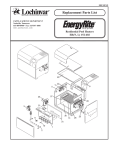

![[1.7 APPLICATION FUNCT.] (FUn](http://vs1.manualzilla.com/store/data/005865551_1-ec59525967aac13e1fcb9d41d71413ed-150x150.png)