1
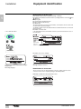
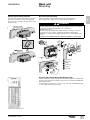
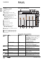
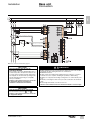
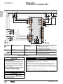
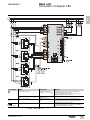
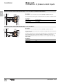
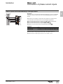
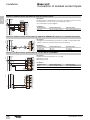
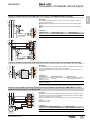
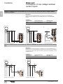
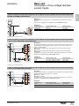
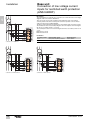
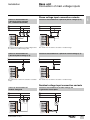
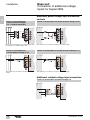
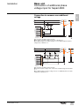
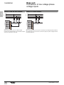
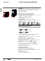
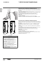
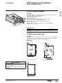
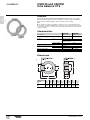
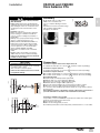
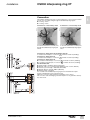
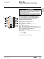
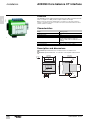
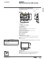
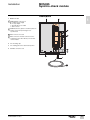
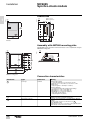
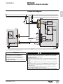
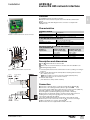
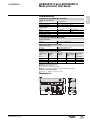
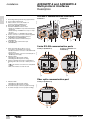
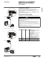
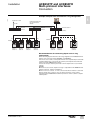
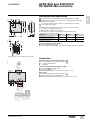
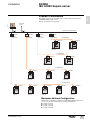
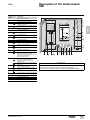
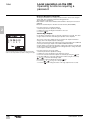
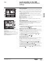
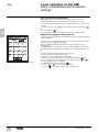
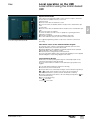
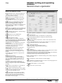
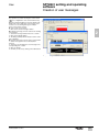
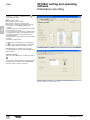
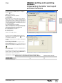
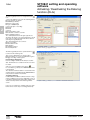
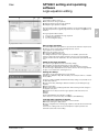
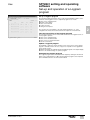
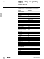
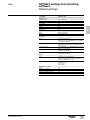
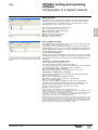
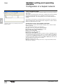
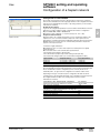
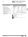
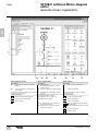
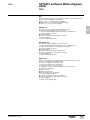
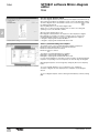
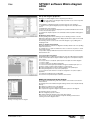
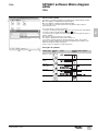
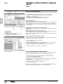
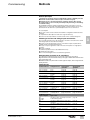
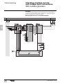
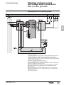
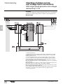
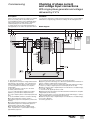
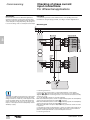
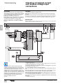
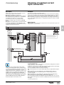
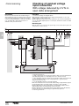
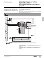
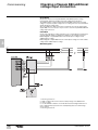
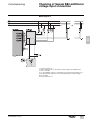
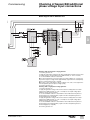
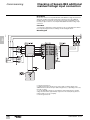
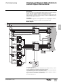
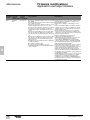
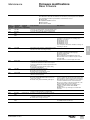
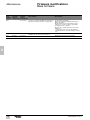
Base unit
Connection of low voltage current
inputs for restricted earth protection
(ANSI 64REF)
Installation
DE80979
N
Parameters
Secondary current
1 A CT
5 A CT
Rated residual current
In0 = phase CT primary current In
In0 = phase CT primary current In
Measuring range
0.01 to 20 In0
0.01 to 20 In0
DE80981
Connection on TT network.
DE80980
1
Description
These 3 diagrams correspond to the connections as found in the various low voltage
diagrams where the neutral is distributed.
They are used to work out the residual current (taking the sum of the 3 phase
currents) and the transformer neutral point current for operation of the restricted
earth protection function (ANSI 64 REF).
The phase and neutral CTs should have the same primary and secondary currents.
The residual current is measured by taking the sum of the 3 phase currents using the
CT whose secondary current is 1 A or 5 A.
The neutral point current is measured using the CT whose secondary current is 1 A
or 5 A:
b Terminal 7: 1 A CT
b Terminal 8: 5 A CT
N
PE
Connection on TN-S network.
26
PEN
Connection on TN-C network.
SEPED303003EN - 01/2013