1
Maintenance Procedures
®
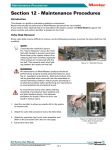
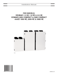
Section 12 - Maintenance Procedures
Introduction
This chapter is a guide to maintaining selective components.
Repairs that should be performed by Mold-Masters personnel are not included.
If you need an item repaired that is not included in this section, please call Mold-Masters support. The phone number and system identifier is located on the mold.
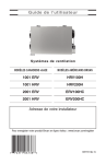
Valve Disk Removal
Some valve disks may be difficult to remove, use the following procedure to extract the valve disk from the manifold.
NOTE
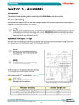
Check that the manifold is secure.
F
or “Cast in Systems” secure the manifold
with clamps to prevent movement.
N
ever heat up the system without first
clamping the main manifold, especially if
the nozzles are not secured with the hot
half. This prevents resin from leaking between the nozzle and hot half.
Figure 12-1 Manifold Clamps
WARNING
All maintenance on Mold-Masters products should be performed by properly trained personnel based on local law
or regulation requirements. Electrical products may not be
grounded when removed from the assembled or normal
operating condition. Assure proper grounding of all electrical
products before performing any maintenance to avoid potential risk of electrical shock.
1
To avoid serious burns wear safety clothing
consisting of a protective heat resistant coat
and heat-resistant gloves. Use adequate
ventilation for fumes. Failure to do so can
result in serious injury.
2
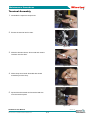
1. Heat the manifold to allow any plastic still in the system to
become soft.
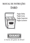
2. Attach the valve disk extraction tool to the valve disk.
3. Attach the extraction tool to the main assembly tool. Refer to
Figure 12-2 Valve Disk Extracted
1. Valve Disk Extraction Tool
2. Valve Disk
the extraction tool chart on next page.
4. Extract the valve disk.
Hot Runner User Manual
Not under documentation control if printed. May be revised without notice. Electronic version is available at www.moldmasters.com
12-1
Revision 14
©06-2011
Maintenance Procedures
®
EXTRACTION TOOLS
Part Number
EXTOOL07
(Ø35)
EXTOOL08
(Ø39)
EXTOOL12
(Ø49)
EXTRACTION TOOLS
Where Used
Valve Disk
Nozzle Type
VD0035
Where Used
Part Number
Valve Disk
Nozzle Type
Pico
VD0088B
Femto
VD0033
Pico
VD0094B
Femto
VD0085
Femto
VD0108B
Femto
VD0089
Femto
VD0109B
Femto
VD0102
Femto
VD0074B
Pico
Pico
EXTOOL10P
('V' Guide)
VD0013
Centi
VD0110B
VD0022
Centi
VD0075B
Centi
VD0069
Centi
VD0111B
Centi
VD0034
Pico
VD0106B
Deci
VD0036
Pico
VD0087B
Femto
VD0037
Pico
VD0093B
Femto
VD0038
Pico
VD0065B
Pico
VD0027
Centi
VD0066B
Centi
VD0028
Centi
VD0031
Deci
VD0032
Deci
EXTOOL10P1
('V' Guide)
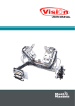
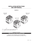
Terminal End Removal and Installation
Although this procedure shows a nozzle terminal end, the process is the same for manifold terminal ends.
Terminal End Removal
1. If the terminal end is covered with plastic, warm the terminal end prior to removing the element sleeve.
CAUTION
Care must be taken when removing the
element sleeve as not to damage the ceramic sleeve or terminal nut.
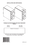
5
4
3
2
1
2. Grip the element sleeve at the threaded area and turn counter clockwise. If the wires rotate with the sleeve, damage
may result.
3. Remove the seal.
4. Remove the set screw from the ceramic sleeve.
5. Remove the power leads.
Figure 12-3 Nozzle Terminal Assembly
1. Nozzle Flange 2. Ceramic Insert
3. Ceramic Sleeve 4. Seal 5. Element Sleeve
Terminal Installation
Although this procedure shows a manifold, the process is the same for nozzle terminal ends.
NOTE
Please contact Mold-Masters Spare Parts Department to ensure you have the correct repair kit
and crimping tool.
Hot Runner User Manual
Not under documentation control if printed. May be revised without notice. Electronic version is available at www.moldmasters.com
12-2
Revision 14
©06-2011
Maintenance Procedures
®
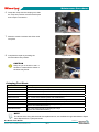
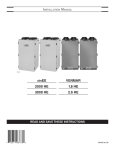
Terminal Assembly
1. Assemble the repair kit components.
Figure 12-4
2. Ensure the terminal end is clean.
Figure 12-5
3. Slide the element sleeve, silicon seal and ceramic
insulator onto the wires.
Figure 12-6
4. Slide crimps onto leads. Stranded wire should
extend beyond the crimp.
Figure 12-7
5. Spread the wire strands and insert the lead wire
onto the terminal posts.
Figure 12-8
Hot Runner User Manual
Not under documentation control if printed. May be revised without notice. Electronic version is available at www.moldmasters.com
12-3
Revision 14
©06-2011
Maintenance Procedures
®
6. Grasp the crimp with the crimping tool, slide
the crimp into position over the terminal post
and crimp the connection.
Figure 12-9
7. Slide the ceramic insulator and silicon seal
into place.
8. Complete the repair by screwing the
Figure 12-10
element sleeve into position.
CAUTION
Keep an eye on the silicon seal. It
should not rotate with the sleeve or
the wires may break.
Figure 12-11
Crimping Tool Chart
Product Name
Description
PUNCHHANDLE01
Ratchet Crimp, tool for attaching dies to terminal end assemblies
CRIMPDIE01
4.0mm Heater Element (Mates with CRIMPPUNCH01)
CRIMPPUNCH01
4.0mm Heater Element (Mates with CRIMPDIE01)
CRIMPDIE02
2.5 - 3.0mm Heater Element (Mates with CRIMPPUNCH02)
CRIMPPUNCH02
2.5 - 3.0mm Heater Element (Mates with CRIMPDIE02)
CRIMPDIE03
1.8 - 2.0mm Heater Element (Mates with CRIMPPUNCH03)
CRIMPPUNCH03
1.8 - 2.0mm Heater Element (Mates with CRIMPDIE03)
CRIMPREMOVEB01
Bottom Crimp Removal Insert for shearing HE crimps
(Mates with CRIMPREMOVET01)
CRIMPREMOVET01
Top Crimp Removal Insert for shearing HE crimps
(Mates with CRIMPREMOVEB01)
NOTE
The
above tools, along with the lead wire replacement kit, are available through Mold-Masters Spare
Parts Department at 1-(800)-387-2483.
Hot Runner User Manual
Not under documentation control if printed. May be revised without notice. Electronic version is available at www.moldmasters.com
12-4
Revision 14
©06-2011
Maintenance Procedures
®
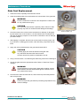
Heater Plate Power Lead Replacement
Removal
1. Remove the set screws.
2. Slide ceramic sleeve off.
3. Remove the power leads using crimp removal tool.
4
3
2
Installation
3
1. Push the replacement leads into the holes in the
1
ceramic sleeve.
Figure 12-12 Terminal Ends Assembly
2. Crimp the leads to the terminal ends.
1. Power Leads 2. Ceramic Sleeve
3. Set Screws 4. Heater Plate
3. Slide ceramic sleeve over the terminal end.
4. Tighten the set screws on the ceramic sleeve to secure the terminal assembly.
Gate Seal Maintenance
Reasons for Gate Seal Maintenance
•
•
•
•
Tip damage
Obstruction to melt flow
Gate seal damage
Tip wear
Multi-Cavity Systems
It is advisable to heat the system to ensure the temperature condition is
met to remove the gate seals.
Figure 12-13 Gate Seals
NOTE
Use the socket supplied in the Mold-Masters tool kit to loosen the gate seal.
It is recommended to use a temperature controller for this procedure. If a temperature controller is not
available, contact your nearest Mold-Masters Service Department.
For gate seal installation and torquing procedures refer to "Gate Seal Replacement" section.
Hot Runner User Manual
Not under documentation control if printed. May be revised without notice. Electronic version is available at www.moldmasters.com
12-5
Revision 14
©06-2011
Maintenance Procedures
®
Gate Seal Removal
The following procedure applies to all gate seals (including carbide) with threads larger than an M6
(Excluding TIT Edge).
NOTE
If the cavity plate is easily removed you can access the
nozzle seals while still in the system.
Hot runner systems must be within 70°F (40°C) of mold
temperature before the cavity plate can be removed.
It is recommended the nozzle be removed from the
system before removing the gate seal.
CAUTION
Seals and liners for Accu-Valve EX & CX are a sub-assembly utilizing a manufactured interference fit. Disassembly of this sub-assembly may affect alignment of
the valve pin to the gate, causing wear.
Figure 12-14
Penetrating Lubricant
NOTE
Use the socket supplied in the Mold-Masters tool kit to
loosen the gate seal.
1. Apply penetrating lubricant to gate seal area.
WARNING
High temperature on the nozzle. Wear safety clothing
such as heat-resistant coat and heat-resistant gloves.
Failure to do so may cause serious injury.
CAUTION
The terminal end is a sensitive area and can easily
break if not handled to specifications.
2. Leave the nozzle in the mold or remove it to a vice and clamp carefully.
3. Using the temperature controller, heat the nozzle body until all
residual plastic is melted from the gate area. If the nozzle is inside
the mold, heat up the whole system and turn on the cooling or
remove all O-rings.
Figure 12-15 Remove Gate
Seal
4. While the nozzle is still hot, apply a loosening pressure to the gate
using the socket to remove the seal.
5. Turn off the controller and wait for 5 minutes.
6. Remove the gate seals.
Hot Runner User Manual
Not under documentation control if printed. May be revised without notice. Electronic version is available at www.moldmasters.com
12-6
Revision 14
©06-2011
Maintenance Procedures
®
Gate Seal Replacement
1. Clean the nozzle, especially the thread and runner.
2. Clean all residual plastic from the threads and counter bore of the gate seal.
A
WARNING
Ensure nozzles have cooled to room temperature. Failure to do
so may cause serious injury.
A
CAUTION
It is critical that seal surface is perfectly clean. Failure to clean
properly may result in nozzle and seal damage and leakage.
Figure 12-16 Cleaning Location
Remove Plastic (A)
3. Check the bottom face of the nozzle counterbore for damage. If damaged,
lap the bottom face of the nozzle in a circular fashion with a hardened tool
and 300 grit lapping compound. If the nozzle counterbore is free of damage,
proceed to step 5.
4. After lapping is complete, blue the liner to the nozzle to ensure proper mating. If the liner is making good contact, clean the bluing compound off both
faces.
5. Apply anti-seize (nickel based) to the gate seal threads ONLY.
CAUTION
Carefully apply anti-seize to threads of the gate seal.
Any anti-seize that enters the internal runner
must be removed to prevent contamination of melt.
6. Using a socket wrench, re-install the gate seal being careful not to damage it.
7. Torque the gate seal to the appropriate value. Refer to "Gate Seal Torque
Settings".
WARNING
High temperature on the nozzle. Wear safety clothing such as
heat-resistant coat and heat-resistant gloves. Failure to do so
may cause serious injury.
8. Check that the seal has bottomed out, heat nozzle to process temperature
and re-torque seal.
WARNING
Failure to torque the gate seals at processing temperatures may
result in leakage.
Figure 12-17 Nozzle Preparation
Hot Runner User Manual
Not under documentation control if printed. May be revised without notice. Electronic version is available at www.moldmasters.com
12-7
Revision 14
©06-2011
Maintenance Procedures
®
Sprint Gate Seal Maintenance
Reasons for Gate Seal Maintenance
•
•
•
•
Assembled
Nozzle Tip
Liner
Tip damage
Obstruction to melt flow
Gate seal damage
Tip wear
Gate Seal
It is advisable to heat the nozzle to ensure the temperature condition is met to remove the gate seal.
Insulator
Cap
CAUTION
Use the socket supplied in the tool
kit to loosen the gate seal.
Figure 12-18 Sprint Gate Seal Components
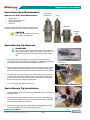
Sprint Nozzle Tip Removal
IMPORTANT
The hot runner system must be turned off and cooled to
below 38ºC (100ºF) before cavity plate is removed. The
cavity plate can then be removed to expose the nozzle
tips.
1. After gate seals are exposed by removing the cavity plate, heat
nozzles only to 290ºC (550°F) if nozzle thermocouples are present or
set nozzle to 20% power until plastic softens in gate area.
Figure 12-19 Tool Kit for Gate Seal
Maintenance
2. Apply loosening torque to the gate seal using 6 point socket provided
(16mm socket). If the seal starts to loosen, but starts to bind, apply
some Pro-Long super lubricant to remove the gate seal more easily.
3. The gate seal, liner and insulator cap should come off the nozzle as
an assembly. If the liner remains in the nozzle after the gate seal is
removed, raise the nozzle temperature by 15ºC (25°F) or 5% power
and remove the liner using soft jawed pliers.
4. Turn off heaters after gate seal removal.
Figure 12-20 Loosening Gate Seal
Sprint Nozzle Tip Installation
1. Clean all residual plastic from the nozzle threads and the liner/nozzle
sealing surface.
2. Check the liner/nozzle sealing surface for damage. If damaged, lap
the liner/nozzle sealing surface in a circular fashion with a hardened
tool and 300 grit lapping compound.
3. After a smooth liner/nozzle contact surface is established, blue the
liner to the nozzle surface to ensure proper mating.
Hot Runner User Manual
Not under documentation control if printed. May be revised without notice. Electronic version is available at www.moldmasters.com
12-8
Figure 12-21 Applying blue to liner surface
Revision 14
©06-2011
Maintenance Procedures
®
4. After ensuring good contact, clean bluing off both surfaces.
5. Apply nickel based anti-seize to the gate seal threads ONLY.
Figure 12-22 Applying anit-seize
6. Install gate seal / liner into nozzle using 6 point socket provided.
Torque gate seal to 25-28 ft lb (34-38 Nm).
Figure 12-23 Torquing gate seal onto
nozzle
Cleaning Nozzle Insulator Cap
1. Heat cap with heat gun.
2. Remove molten plastic and wipe remainder from
insulator cap.
Figure 12-24 Cleaning Insulator Cap
Installing Nozzle
Insulator Cap
1. Press fit insulator cap onto liner
by hand.
Figure 12-25 Installing Insulator Cap
Hot Runner User Manual
Not under documentation control if printed. May be revised without notice. Electronic version is available at www.moldmasters.com
12-9
Revision 14
©06-2011
Maintenance Procedures
®
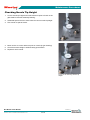
Checking Nozzle Tip Height
1. Correct nozzle tip height and nozzle reference point is found on the
gate detail of General Assembly Drawing.
2. Assemble spacer blocks to same value as correct nozzle tip height.
3. Zero vernier to spacer blocks.
4. Move vernier to correct reference point on nozzle tip (per drawing).
5. Check that nozzle height is within drawing specification.
6. Repeat for each nozzle.
Figure 12-26 Checking Nozzle Tip
Height
Hot Runner User Manual
Not under documentation control if printed. May be revised without notice. Electronic version is available at www.moldmasters.com
12-10
Revision 14
©06-2011
Maintenance Procedures
®
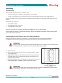
Latching
Introduction
There are two reasons latches are used in a mold:
•
•
To tie the mold halves together for transportation and handling.
To gain access between two mold plates which are screwed together during normal mold operation.
Latches are always used in pairs mounted on diagonally opposite sides of the mold to provide equal pull on the
plates.
The latches are located on:
•
•
•
The operator’s side.
Non-operator’s side of the mold.
Top and bottom of the mold.
Under no circumstances are plates to be pulled or handled with only one latch attached.
Latch locations are shown on the assembly drawings. During mold operation the latches must be removed from
the mold and stored elsewhere.
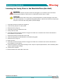
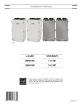
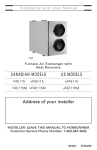
Latching the Cavity Plate to the Core Half (Cold Half)
Use this procedure for reference purposes only. For latch locations, refer to the assembly drawings.
For additional instructions on latching in the machine refer to the machine manufacturers manual.
WARNING
Make sure the machine has been locked out and tagged out in accordance to the machines documented procedures. Failure to do so may lead to serious injury or death.
1
1. Open the mold.
2. Ensure that the machine and hot runner controller has been locked
out and tagged out.
2
3. Apply lock out / tag out to the machine power source and hot runner
controller. Refer to the controller and machine manufacturers documentation for procedures.
3
4. Allow the mold to cool to room temperature. Continue to circulate the
mold cooling water in all plates to cool the mold more quickly.
1
Figure 12-27 Latch Cavity Plate to
Manifold Plate
1. Latches 2. Manifold Plate
3. Cavity Plate
WARNING
Make sure the lifting eyebolt, lifting chain and crane are rated to adequately support the weight of the plate(s). Failure to do so could cause serious injury.
Hot Runner User Manual
Not under documentation control if printed. May be revised without notice. Electronic version is available at www.moldmasters.com
12-11
Revision 14
©06-2011
Maintenance Procedures
®
5. If the mold has no leader pins, attach a crane that is rated to adequately support the weight of the cavity
plate.
WARNING
Install latches before removing the cavity plate mounting screws. Failure to do so may lead to
serious injury or death.
6. Latch the cavity plate to the manifold or manifold backing plate.
7. Check that the cavity plate hoses are long enough to allow the cavity
plate to be latched over to the core half (cold half), without damaging
the hoses.
3
2
8. Remove all cavity plate mounting screws.
5
4
9. Remove lockout / tagged out.
1
10. Place the machine in Mold Set mode.
11. Close the mold slowly.
WARNING
Make sure the machine has been locked out and tagged
out in accordance to the machines documented procedures. Failure to do so may lead to serious injury or
death.
2
Figure 12-28 Cavity Plate to Core Plate
1. Stationary Platen 2. Latches
3. Moving Platen
4. Core Plate 5. Cavity Plate
12. Apply lockout / tagged out. Refer to machine manufacturers documentation for procedures.
13. Remove the latches.
1
3
14. Latch the cavity plate to the core plate or cold half.
4
15. Remove lockout / tagged out.
2
16. Check the machine is in Mold Set mode.
17. Open the mold moving the cavity plate away from the manifold plate.
18. Apply lockout / tagged out. Refer to the controller and machine
manufacturers documentation for procedures.
CAUTION
The nozzles must be within 100°F (55°C) of mold
temperature to prevent damage to hot runner and mold
components. For cylindrical valve gated systems, valve
pins should be in the open position prior to removal of
the cavity plate to prevent damage.
Hot Runner User Manual
Not under documentation control if printed. May be revised without notice. Electronic version is available at www.moldmasters.com
12-12
Figure 12-29 Latch Cavity Plate to Core
Plate
1. Stationary Platen 2. Cavity Plate
3. Moving Platen 4. Core Plate
Revision 14
©06-2011
Maintenance Procedures
®
Latching the Cavity Plate to the Manifold Plate (Hot Half)
WARNING
Make sure the machine has been locked out and tagged out in accordance to the machines
documented procedures. Failure to do so could lead to serious injury or death.
CAUTION
The nozzles must be within 100°F (55°C) of mold temperature to prevent damage to hot runner
and mold components. For cylindrical valve gated systems, valve pins should be in the open position prior to removal of the cavity plate to prevent damage.
1. Check the machine is locked out / tagged out.
2. Lubricate the guide pins on the hot half.
3. Remove lock out / tag out.
4. Check the machine is in Mold Set mode.
5. Slowly close the mold.
6. Check the machine has been locked out / tagged out. Refer to the controller and machine manufacturers
documentation for procedures.
7. Remove the latches on both sides of the mold.
8. Latch the cavity plate to manifold plate or manifold backing plate.
9. Remove lock out / tag out.
10. Open the mold.
11. Check the machine has been locked out / tagged out. Refer to the controller and machine manufacturers
documentation for procedures.
12. Install and torque the cavity plate mounting screws. Torque to required specifications, refer to assembly drawings for required torque settings.
13. Install hoses if required.
14. Remove latches from both sides of the mold.
Hot Runner User Manual
Not under documentation control if printed. May be revised without notice. Electronic version is available at www.moldmasters.com
12-13
Revision 14
©06-2011
Maintenance Procedures
®
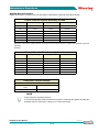
Torque Settings
Gate Seal Torque Settings
Seal Torque Settings
Gating
Method
FemtoLite
Femto
Pico
Centi
Deci
Hecto
Nm
ft-lb
Nm
ft-lb
Nm
ft-lb
Nm
ft-lb
Nm
ft-lb
Nm
ft-lb
E-Type Torpedo
8-9
6-7
8-9
6-7
16-18
12-13
27-30
20-22
34-38
25-28
47-54
35-40
Ext. E-Type Torpedo
8-9
6-7
F-Type Torpedo
8-9
6-7
8-9
6-7
16-18
12-13
27-30
20-22
34-38
25-28
47-54
35-40
8-9
6-7
Hot Sprue
16-18
12-13
27-30
20-22
34-38
25-28
47-54
35-40
16-18
12-13
27-30
20-22
34-38
25-28
47-54
35-40
16-18
12-13
27-30
20-22
34-38
25-28
47-54
35-40
16-18
12-13
27-30
20-22
34-38
25-28
47-54
35-40
16-18
12-13
27-30
20-22
34-38
25-28
Bi-Metallic C-Valve
16-18
12-13
27-30
20-22
34-38
25-28
47-54
35-40
Spiral Hot Tip
16-18
12-13
27-30
20-22
34-38
25-28
47-54
35-40
16-18
12-13
27-30
20-22
34-38
25-28
11-14
8-10
14-15
10-11
14-15
10-11
16-18
12-13
27-30
20-22
15-18
11-13
15-18
11-13
Extended Hot Sprue
Hot Valve
8-9
6-7
8-9
6-7
Bi-Metallic C-Sprue
Bi-Metallic Cylindrical
Valve
Accu-Valve™
8-9
6-7
TIT Edge
Multi Tip
Horizontal Hot Tip
C-Sprue
8-9
C-Valve
6-7
8-9
6-7
8-9
6-7
NOTE
Gate seals are torqued at ambient (room) temperature at Mold-Masters. Please torque each seal at processing temperature to the torque value specified. This is to prevent material
leakage from the gate seal.
Hot Runner User Manual
Not under documentation control if printed. May be revised without notice. Electronic version is available at www.moldmasters.com
12-14
Revision 14
©06-2011
Maintenance Procedures
®
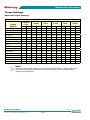
System Screw Torques
Quality and length of screws must be as specified on Mold-Masters general assembly drawings.
Torque Chart for System Assembly Screws
Metric
Torque Setting
Imperial
Torque Setting
M5
7 Nm
#10-32
5 ft lbs
M6
14 Nm
1/4-20
10 ft lbs
M8
20 Nm
5/16-18
15 ft lbs
M10
40 Nm
3/8-16
30 ft lbs
M12
60 Nm
1/2-13
45 ft lbs
M16
145 Nm
5/8-11
107 ft lbs
M20
285 Nm
3/4-10
210 ft lbs
Exception to the above, bridge manifold mounting screws should be torqued 1/3 higher then specified on general
assembly
drawings.
Torque Chart for Plate Assembly Screws
Metric
Torque Setting
Imperial
Torque Setting
M5
10 Nm / 7 ft lbs
#10-32
9 Nm / 6 ft lbs
M6
16 Nm / 12 ft lbs
1/4-20
22 Nm / 16 ft lbs
M8
39 Nm / 29 ft lbs
5/16-18
48 Nm / 35 ft lbs
M10
77 Nm / 57 ft lbs
3/8-16
85 Nm / 63 ft lbs
M12
M16
135 Nm / 100 ft lbs
330 Nm / 243 ft lbs
1/2-13
5/8-11
209 Nm / 154 ft lbs
384 Nm / 283 ft lbs
M20
650 Nm / 479 ft lbs
3/4-10
678 Nm / 500 ft lbs
Component Torque Settings
Valve Actuator
Series 5500, 6500, 6600 and
6700
Torque Setting
Piston Top
20-27 Nm(15-20 ft-lbs)
NOTE
Torque sequence and step torquing:
It is recommended that system screws be torqued in a standard bolt pattern and that the
specified torque is achieved in 3 steps (1/3, 2/3 and full torque).
Hot Runner User Manual
Not under documentation control if printed. May be revised without notice. Electronic version is available at www.moldmasters.com
12-15
Revision 14
©06-2011