1
Interface-Based Design™ Tutorial
for HDL Author and HDL Designer
Software Version 2013.1
December 2013
© 1996-2013 Mentor Graphics Corporation
All rights reserved.
This document contains information that is proprietary to Mentor Graphics Corporation. The original recipient of this
document may duplicate this document in whole or in part for internal business purposes only, provided that this entire
notice appears in all copies. In duplicating any part of this document, the recipient agrees to make every reasonable
effort to prevent the unauthorized use and distribution of the proprietary information.
This document is for information and instruction purposes. Mentor Graphics reserves the right to make
changes in specifications and other information contained in this publication without prior notice, and the
reader should, in all cases, consult Mentor Graphics to determine whether any changes have been
made.
The terms and conditions governing the sale and licensing of Mentor Graphics products are set forth in
written agreements between Mentor Graphics and its customers. No representation or other affirmation
of fact contained in this publication shall be deemed to be a warranty or give rise to any liability of Mentor
Graphics whatsoever.
MENTOR GRAPHICS MAKES NO WARRANTY OF ANY KIND WITH REGARD TO THIS MATERIAL
INCLUDING, BUT NOT LIMITED TO, THE IMPLIED WARRANTIES OF MERCHANTABILITY AND
FITNESS FOR A PARTICULAR PURPOSE.
MENTOR GRAPHICS SHALL NOT BE LIABLE FOR ANY INCIDENTAL, INDIRECT, SPECIAL, OR
CONSEQUENTIAL DAMAGES WHATSOEVER (INCLUDING BUT NOT LIMITED TO LOST PROFITS)
ARISING OUT OF OR RELATED TO THIS PUBLICATION OR THE INFORMATION CONTAINED IN IT,
EVEN IF MENTOR GRAPHICS HAS BEEN ADVISED OF THE POSSIBILITY OF SUCH DAMAGES.
U.S. GOVERNMENT LICENSE RIGHTS: The software and documentation were developed entirely at
private expense and are commercial computer software and commercial computer software
documentation within the meaning of the applicable acquisition regulations. Accordingly, pursuant to
FAR 48 CFR 12.212 and DFARS 48 CFR 227.7202, use, duplication and disclosure by or for the U.S.
Government or a U.S. Government subcontractor is subject solely to the terms and conditions set forth
in the license agreement provided with the software, except for provisions which are contrary to
applicable mandatory federal laws.
TRADEMARKS: The trademarks, logos and service marks ("Marks") used herein are the property of
Mentor Graphics Corporation or other parties. No one is permitted to use these Marks without the prior
written consent of Mentor Graphics or the owner of the Mark, as applicable. The use herein of a thirdparty Mark is not an attempt to indicate Mentor Graphics as a source of a product, but is intended to
indicate a product from, or associated with, a particular third party. A current list of Mentor Graphics’
trademarks may be viewed at: www.mentor.com/trademarks.
Mentor Graphics Corporation
8005 S.W. Boeckman Road, Wilsonville, Oregon 97070-7777
Telephone: 503.685.7000
Toll-Free Telephone: 800.592.2210
Website: www.mentor.com
SupportNet: supportnet.mentor.com/
Send Feedback on Documentation: supportnet.mentor.com/doc_feedback_form
Table of Contents
Interface-Based Design Tutorial . . . . . . . . . . . . . . . . . . . . . . . . . . . . . . . . . . . . . . . . . . . . . .
Overview . . . . . . . . . . . . . . . . . . . . . . . . . . . . . . . . . . . . . . . . . . . . . . . . . . . . . . . . . . . . . . . .
Introduction . . . . . . . . . . . . . . . . . . . . . . . . . . . . . . . . . . . . . . . . . . . . . . . . . . . . . . . . . . . . . .
Specification . . . . . . . . . . . . . . . . . . . . . . . . . . . . . . . . . . . . . . . . . . . . . . . . . . . . . . . . . . . . .
Set Library Mapping . . . . . . . . . . . . . . . . . . . . . . . . . . . . . . . . . . . . . . . . . . . . . . . . . . . . . . .
Set the Default Language. . . . . . . . . . . . . . . . . . . . . . . . . . . . . . . . . . . . . . . . . . . . . . . . . . . .
Create a Tabular IO View . . . . . . . . . . . . . . . . . . . . . . . . . . . . . . . . . . . . . . . . . . . . . . . . . . .
Add Ports . . . . . . . . . . . . . . . . . . . . . . . . . . . . . . . . . . . . . . . . . . . . . . . . . . . . . . . . . . . . . .
Add Groups. . . . . . . . . . . . . . . . . . . . . . . . . . . . . . . . . . . . . . . . . . . . . . . . . . . . . . . . . . . . .
Save the Interface . . . . . . . . . . . . . . . . . . . . . . . . . . . . . . . . . . . . . . . . . . . . . . . . . . . . . . . .
Display the Graphical Symbol . . . . . . . . . . . . . . . . . . . . . . . . . . . . . . . . . . . . . . . . . . . . . .
Adding the HDL Text Views. . . . . . . . . . . . . . . . . . . . . . . . . . . . . . . . . . . . . . . . . . . . . . . . .
Browse the Imported Text Views . . . . . . . . . . . . . . . . . . . . . . . . . . . . . . . . . . . . . . . . . . . .
Create an Interface-Based Design View . . . . . . . . . . . . . . . . . . . . . . . . . . . . . . . . . . . . . . . .
Add the Datapath Block . . . . . . . . . . . . . . . . . . . . . . . . . . . . . . . . . . . . . . . . . . . . . . . . . . .
Add ModuleWare Components . . . . . . . . . . . . . . . . . . . . . . . . . . . . . . . . . . . . . . . . . . . . .
Modify the ModuleWare Parameters . . . . . . . . . . . . . . . . . . . . . . . . . . . . . . . . . . . . . . . . .
Add Signal Connections . . . . . . . . . . . . . . . . . . . . . . . . . . . . . . . . . . . . . . . . . . . . . . . . . . .
Browse the Completed Design. . . . . . . . . . . . . . . . . . . . . . . . . . . . . . . . . . . . . . . . . . . . . . . .
Generate HDL for the Hierarchy . . . . . . . . . . . . . . . . . . . . . . . . . . . . . . . . . . . . . . . . . . . .
Adding the Test Bench. . . . . . . . . . . . . . . . . . . . . . . . . . . . . . . . . . . . . . . . . . . . . . . . . . . . . .
Setup the Downstream Tools . . . . . . . . . . . . . . . . . . . . . . . . . . . . . . . . . . . . . . . . . . . . . . . . .
Run the ModelSim Flow . . . . . . . . . . . . . . . . . . . . . . . . . . . . . . . . . . . . . . . . . . . . . . . . . . . .
Run the LeonardoSpectrum Flow . . . . . . . . . . . . . . . . . . . . . . . . . . . . . . . . . . . . . . . . . . . . .
View the RTL Schematic . . . . . . . . . . . . . . . . . . . . . . . . . . . . . . . . . . . . . . . . . . . . . . . . . .
5
5
6
8
9
11
13
14
15
16
18
19
21
22
26
29
29
31
34
35
36
38
39
43
46
End-User License Agreement
Interface-Based Design Tutorial, V2013.1
December 2013
3
Table of Contents
4
Interface-Based Design Tutorial, V2013.1
December 2013
Interface-Based Design Tutorial
This tutorial exercise shows how to capture a simple calculator design by defining logical
interfaces in a tabular format using Interface-Based Design views (IBD).
Overview . . . . . . . . . . . . . . . . . . . . . . . . . . . . . . . . . . . . . . . . . . . . . . . . . . . . . . . . . . . . . . . .
Introduction . . . . . . . . . . . . . . . . . . . . . . . . . . . . . . . . . . . . . . . . . . . . . . . . . . . . . . . . . . . . .
Specification . . . . . . . . . . . . . . . . . . . . . . . . . . . . . . . . . . . . . . . . . . . . . . . . . . . . . . . . . . . . .
Set Library Mapping . . . . . . . . . . . . . . . . . . . . . . . . . . . . . . . . . . . . . . . . . . . . . . . . . . . . . .
Set the Default Language . . . . . . . . . . . . . . . . . . . . . . . . . . . . . . . . . . . . . . . . . . . . . . . . . .
Create a Tabular IO View. . . . . . . . . . . . . . . . . . . . . . . . . . . . . . . . . . . . . . . . . . . . . . . . . .
Add Ports . . . . . . . . . . . . . . . . . . . . . . . . . . . . . . . . . . . . . . . . . . . . . . . . . . . . . . . . . . . . . .
Add Groups. . . . . . . . . . . . . . . . . . . . . . . . . . . . . . . . . . . . . . . . . . . . . . . . . . . . . . . . . . . . .
Save the Interface . . . . . . . . . . . . . . . . . . . . . . . . . . . . . . . . . . . . . . . . . . . . . . . . . . . . . . . .
Display the Graphical Symbol . . . . . . . . . . . . . . . . . . . . . . . . . . . . . . . . . . . . . . . . . . . . . .
Adding the HDL Text Views. . . . . . . . . . . . . . . . . . . . . . . . . . . . . . . . . . . . . . . . . . . . . . . .
Browse the Imported Text Views . . . . . . . . . . . . . . . . . . . . . . . . . . . . . . . . . . . . . . . . . . . .
Create an Interface-Based Design View . . . . . . . . . . . . . . . . . . . . . . . . . . . . . . . . . . . . . .
Add the Datapath Block . . . . . . . . . . . . . . . . . . . . . . . . . . . . . . . . . . . . . . . . . . . . . . . . . . .
Add ModuleWare Components . . . . . . . . . . . . . . . . . . . . . . . . . . . . . . . . . . . . . . . . . . . . .
Modify the ModuleWare Parameters . . . . . . . . . . . . . . . . . . . . . . . . . . . . . . . . . . . . . . . . .
Add Signal Connections . . . . . . . . . . . . . . . . . . . . . . . . . . . . . . . . . . . . . . . . . . . . . . . . . . .
Browse the Completed Design . . . . . . . . . . . . . . . . . . . . . . . . . . . . . . . . . . . . . . . . . . . . . .
Generate HDL for the Hierarchy . . . . . . . . . . . . . . . . . . . . . . . . . . . . . . . . . . . . . . . . . . . .
Adding the Test Bench . . . . . . . . . . . . . . . . . . . . . . . . . . . . . . . . . . . . . . . . . . . . . . . . . . . .
Setup the Downstream Tools . . . . . . . . . . . . . . . . . . . . . . . . . . . . . . . . . . . . . . . . . . . . . . .
Run the ModelSim Flow . . . . . . . . . . . . . . . . . . . . . . . . . . . . . . . . . . . . . . . . . . . . . . . . . . .
5
6
8
9
11
13
14
15
16
18
19
21
22
26
29
29
31
34
35
36
38
39
Run the LeonardoSpectrum Flow . . . . . . . . . . . . . . . . . . . . . . . . . . . . . . . . . . . . . . . . . . .
View the RTL Schematic . . . . . . . . . . . . . . . . . . . . . . . . . . . . . . . . . . . . . . . . . . . . . . . . . .
43
46
Overview
This manual provides a self-paced tutorial with step-by-step procedures showing you how to
import and capture a HDL text design using tabular Interface-Based DesignTM views (IBD) and
imported HDL text. ModuleWare components are added to complete the design before
generation, compilation and synthesis.
The tutorial covers the basic procedures required to fully define and verify a design using
tabular views. The full tutorial can be completed by users of the HDL AuthorTM or HDL
Interface-Based Design Tutorial, V2013.1
December 2013
5
Interface-Based Design Tutorial
Introduction
DesignerTM tools using tabular IO and IBD views. The completed design can be compiled and
simulated if ModelSim® is available and synthesized if the LeonardoSpectrumTM tools are
available.
Although the procedures do not describe the use of other tools, the HDL Designer Series
includes support for many alternative downstream tool interfaces and it should be possible to
use the generated HDL with any of these interfaces. However, you must consider any
limitations of your external tool. In particular, some VHDL tools may not support the standard
IEEE packages used in the tutorial and you should substitute an appropriate alternative package.
The tutorial assumes that users have some knowledge of the issues for digital hardware design
and experience of the VHDL or Verilog language.
It is possible to complete the tutorial without this knowledge by carefully copying the language
syntax given in the procedures. However, a separate VHDL or Verilog training course is
recommended in order to fully appreciate how the power of HDL design can be exploited using
tabular design methods.
Introduction
Interface-Based Design allows you to enter design interconnections using a compact tabular
format that can also be viewed as an automatically generated graphical block diagram. The
format is particularly useful for describing silicon core interfaces for new or reusable design
units.
The tabular editing environment allows you to capture a given level of hierarchy piece by piece,
simplifying design creation and documentation. This approach saves design time and enables
the rapid construction of design hierarchy for large and complex designs.
In this exercise, you will create a top level IBD view (Calc_Top) and import three HDL text
component views: Controller, Counter and Decoder. The Controller and Decoder components
are instantiated in the IBD view and signal connections made between them.
The calculator design is completed by adding a Datapath block which is described by an IBD
view containing an instantiation of the Counter component and three ModuleWare components:
acc, mux4, and merge.
The instructions assume that a ModelSim simulator and LeonardoSpectrum synthesis tools are
available. However, HDL generated from the diagrams can also be used by other compatible
downstream tools that are available on your system.
6
Interface-Based Design Tutorial, V2013.1
December 2013
Interface-Based Design Tutorial
Introduction
Note
This tutorial can be completed using either the VHDL or Verilog languages after setting
the default language of your choice in the Main Settings dialog. The Verilog language has
been used for all examples shown in this manual with notes where the VHDL syntax is
different.
Interface-Based Design Tutorial, V2013.1
December 2013
7
Interface-Based Design Tutorial
Specification
Specification
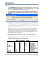
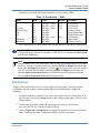
This exercise is based on a simple calculator design which calculates an output Z from two
vector inputs A and B using three functions: add, subtract and multiply determined by the
OpCode input.
OpCode
Function
1
2
3
Z=A+B
Z=A-B
Z=AxB
There are six input ports and three output ports in the external port interface as shown in the
following diagram and table:
8
Port Name
Mode
Description
A [4:0]
input
5-bit data bus
B [4:0]
input
5-bit data bus
OpCode [1:0]
input
2-bit control bus
OpCodeValid
input
Validity control
Clk
input
Single phase clock
Rst
input
Asynchronous reset
Z [4:0]
output
5-bit data bus
DataReady
output
Data ready status signal
Initializing
output
Initialize control
Interface-Based Design Tutorial, V2013.1
December 2013
Interface-Based Design Tutorial
Set Library Mapping
Set Library Mapping
For this tutorial, you can use an existing project (for instance, you can use the examples project)
but should create a new library mapping for your design data.
The library mapping defines the logical location of the directories containing your design data.
The source graphical objects, HDL and downstream data can be stored at any writable locations
on your available file system but are typically saved below a common root directory.
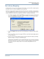
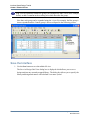
1. To set library mapping, click the New Library icon in the Project group on the shortcut
bar or choose Library from the New cascade of the File menu in the design manager
window to display the New Library wizard:
2. Choose the Regular library type and click the Next button to display the library name
page.
3. Enter a logical library name (for example: IBDTutor) and check that the Auto option is
set in the dialog box.
4. Specify or browse for the pathname for the root directory that will contain your library
data (for example, D:\Designs or $HOME/designs).
Library names and pathnames can be entered using upper, lower or mixed case but note
that UNIX systems are case sensitive and the case used for pathnames should match the
file structure. (On a PC, library names are case sensitive but pathnames are case
insensitive.)
Interface-Based Design Tutorial, V2013.1
December 2013
9
Interface-Based Design Tutorial
Set Library Mapping
Notice that the source HDL directory is named <root_directory>\IBDTutor\hdl and the
source graphics directory is named <root_directory>\IBDTutor\hds.
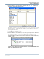
5. Click the Next button to display the last page of the wizard.
6. Set the Make this the Default library and Open this library in the design explorer
options.
7. Click Finish to close the wizard.
10
Interface-Based Design Tutorial, V2013.1
December 2013
Interface-Based Design Tutorial
Set the Default Language
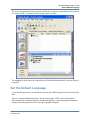
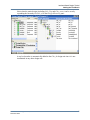
The source design data directories you specified in the wizard are created and the library (shown
as a closed “book”) is opened in a new design explorer window:
The mapping for the location of compiled data will be defined automatically when the design is
compiled.
Set the Default Language
A set of default preferences are loaded when you invoke a HDL Designer Series tool for the first
time.
There are separate tabbed dialog boxes for the main settings, VHDL and Verilog options,
documentation & visualization options, design management, version management, animation
settings and master preferences for each type of graphical diagram.
Interface-Based Design Tutorial, V2013.1
December 2013
11
Interface-Based Design Tutorial
Set the Default Language
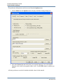
The preference dialog boxes can be accessed from the Options menu.
1. Choose Main from the Options menu to display the Main Settings dialog box.
2. Select the General tab and ensure that your required language is set as the default
language to be used for new graphic editor views. Use the OK button to confirm your
choice.
All other preferences can be left with their default values for this tutorial.
12
Interface-Based Design Tutorial, V2013.1
December 2013
Interface-Based Design Tutorial
Create a Tabular IO View
Create a Tabular IO View
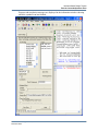
A tabular IO view describes the external interface of a design unit as a spreadsheet like matrix.
1. Create a tabular IO view from the design explorer by clicking the New button and
choosing Interface from the Graphical View cascade of the dropdown menu.
The tabular IO view displays the interface as a matrix of seven columns with a separate
row for each port.
A Delay column is available if you are using Verilog or an Initial column if you are
using VHDL.
In the Structure Navigator pane of the Diagram Browser sub-window you can set
Parameters (if the language is Verilog) or Generics (if the language is VHDL). You
can display a graphical view of the interface by choosing Symbol. You can also define
declarations and package lists.
Related Topics
•
•
•
•
Add Ports
Add Groups
Save the Interface
Display the Graphical Symbol
Interface-Based Design Tutorial, V2013.1
December 2013
13
Interface-Based Design Tutorial
Create a Tabular IO View
Add Ports
1. Use the Add Input Port button to add a port with a default port name, mode, type and
bounds. The default bounds constraint is [15:0] with wire type in Verilog or (15:0) with
std_logic_vector type in VHDL representing a 16-bit bus.
A Generation Order Indicator dialog box is displayed when you add the first port. You
can tick the check box to suppress it in future, and choose to continue by clicking the
OK button...
2. Change the port name to A and the bounds to [4:0] for Verilog or (4:0) for VHDL. You
can edit the port name and constraints by clicking to edit the cell contents or you can
overwrite the cell contents by selecting the existing cell contents and overwriting with
the new data. Complete the port declaration by adding a brief description (for example
5-bit data bus) in the Comment column.
3. Click the Name cell in the second row of the table and enter the port name B. Click the
Left mouse button outside the cell and notice that the last used type and bounds
constraints are automatically entered into the row. Complete the port declaration by
entering a comment and notice how text is automatically completed when you enter
characters that match a previous entry.
4. Repeat these steps to enter the OpCode, OpCodeValid, Clk and Rst input ports.
5. Add the three output ports Z, DataReady and Initializing to the matrix by using the Add
Output Port button or by direct cell entry.
Enter the following information if you are using Verilog:
Table 1-1. Port Entries — Verilog
14
Name
Mode
Type
Bounds
Comment
A
B
OpCode
OpCodeValid
Clk
Rst
Z
DataReady
Initializing
input
input
input
input
input
input
output
output
output
wire
wire
wire
wire
wire
wire
reg
reg
reg
[4:0]
[4:0]
[1:0]
5-bit data bus
5-bit data bus
2-bit control bus
Validity control
Single-phase clock
Asynchronous reset
5-bit data bus
Status signal
Initialize control
[4:0]
Interface-Based Design Tutorial, V2013.1
December 2013
Interface-Based Design Tutorial
Create a Tabular IO View
Alternatively, enter the following information if you are using VHDL:
Table 1-2. Port Entries — VHDL
Name
Mode
Type
Bounds
Comment
A
B
OpCode
OpCodeValid
Clk
Rst
Z
DataReady
Initializing
IN
IN
IN
IN
IN
IN
OUT
OUT
OUT
std_logic_vector
std_logic_vector
std_logic_vector
std_logic
std_logic
std_logic
std_logic_vector
std_logic
std_logic
(4:0)
(4:0)
(1:0)
5-bit data bus
5-bit data bus
2-bit control
Validity control
Single-phase clock
Asynchronous reset
5-bit data bus
Status signal
Initialize control
(4:0)
The Verilog Delay or VHDL Initial value column should be left empty for this tutorial.
Tip: The VHDL bounds is shown in short format by default, for example (4:0), but can
be displayed in long format, for example (4 DOWNTO 0), by unsetting the Short Form
option in the Table menu.
Note
The declaration order is the same as the order in which port declaration rows were added.
However, you can set manual ordering by choosing Switch to Manual from the popup
menu when the Right mouse button is over the
icon. In this mode, you can re-order
rows (by selecting the row number and dragging with the Right mouse button) and
choosing Update Generation Order or re-instate the previous generation order by
choosing Show Generation Order from the popup menu.
Add Groups
Groups can be useful when you have a large design with many ports. You can group port
declarations into any number of named groups which can be individually collapsed or
expanded.
1. Use Ctrl + Left mouse button to select any cell in each of the rows for the ports A, B,
OpCode and Z and use the Group button to add a default group name (Group0) in the
Group column.
2. Use the same procedure to add a default group name (Group1) for the ports
OpCodeValid, Clk, Rst, DataReady and Initializing.
3. Use the Toggle Show Grouped button to toggle the tabular IO view into hierarchical
mode. Notice that the table is collapsed to display only the group titles.
Interface-Based Design Tutorial, V2013.1
December 2013
15
Interface-Based Design Tutorial
Create a Tabular IO View
Tip: You can optionally rename the groups (for example Bus and Control in the example
below) or add a comment in the scrolling area which describes the group.
Note that, each group can be expanded using the + icon. For example, the Bus group is
shown expanded and the Control group is shown collapsed in the following picture:
Save the Interface
1. Use the Save button to save the tabular IO view.
The Save As Design Unit View dialog box is displayed which allows you to save a
design unit into any currently mapped library. The dialog box allows you to specify the
library and design unit names with a default view name symbol.
16
Interface-Based Design Tutorial, V2013.1
December 2013
Interface-Based Design Tutorial
Create a Tabular IO View
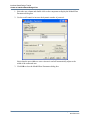
2. Select the IBDTutor library and enter the design unit name Calc_Top. The dialog box
should look similar to the following picture:
You should not attempt to change the default view name symbol as this name is required
by HDL generation. An alternative name should only be used when you want to save a
temporary alternative view.
3. Click OK to save the tabular IO view.
4. Select the IBDTutor library in the Design Units pane of the design explorer and expand
the library by clicking the + icon (or choose Expand All from the popup menu).
A default graphical view has now been created for the interface you have defined using
a tabular IO view:
You can open the interface from the design explorer by choosing Open from the popup
menu or by double-clicking on symbol.
Interface-Based Design Tutorial, V2013.1
December 2013
17
Interface-Based Design Tutorial
Create a Tabular IO View
Display the Graphical Symbol
1. Display the graphical symbol by choosing the Show Component Browser icon in the
Structure Navigator pane of the Diagram Browser tab in the Interface window. The
default graphical symbol should look similar to the following picture:
2. Close the window.
Refer to the “Component Interface Views” chapter in the Graphical Editors User Manual for
more information about the tabular IO and symbol views.
18
Interface-Based Design Tutorial, V2013.1
December 2013
Interface-Based Design Tutorial
Adding the HDL Text Views
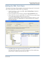
Adding the HDL Text Views
The behavior of the design will be described by four hierarchical design units. For this tutorial,
three of these design units are added as HDL text components.
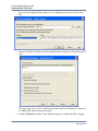
1. In the Design Manager window choose File > Add > Existing Design to display the
Add Existing Design wizard.
2. Specify the method to add your design by setting the Copy Specified Files option.
3. Choose VHDL Files (if you are using VHDL) or Verilog Files (if you are using Verilog)
from the Show Files of Type pulldown filter and check the
<install_dir>\examples\tutorial_ref\Import\Calculator installation subdirectory in the
Folders pane directory tree. Uncheck the Calc_testbench.vhd file or Calc_testbench.v
file in the content pane.
4. Click OK to display the Target Libraries page of the wizard.
The Target Libraries page allows you to specify the library used for the added design
when no library is explicitly specified in the source HDL.
Interface-Based Design Tutorial, V2013.1
December 2013
19
Interface-Based Design Tutorial
Adding the HDL Text Views
You can also change the library used for views added from one or more of the source
files.
5. Choose the IBDTutor library and click the Next button to display the Target Directories
page.
This page allows you to view or edit directory names used by the added files when you
are adding HDL from a directory hierarchy.
6. Click the Finish button on the Target Directories page to complete the HDL copying.
20
Interface-Based Design Tutorial, V2013.1
December 2013
Interface-Based Design Tutorial
Adding the HDL Text Views
The HDL Log Window shows the progress of the import operation. The following
summary report is displayed on completion:
HDL Import complete
------------------------------------------------------------1 file imported to 1 library
-------------------------------------------------------------
Now you can Browse the Imported Text Views in the design explorer.
Browse the Imported Text Views
1. Select the IBDTutor library in the design explorer Design Units browser and choose
Expand All from the popup menu to display the three imported text views.
Notice that each imported design unit contains a HDL text view defined in the HDL file
Calc_Text.v (if you are using Verilog) or Calc_Text.vhd (if you are using VHDL).
2. Select the Calc_Top design unit and choose Toggle Top Marker from the Edit or
popup menu to set a top level marker.
Interface-Based Design Tutorial, V2013.1
December 2013
21
Interface-Based Design Tutorial
Create an Interface-Based Design View
Create an Interface-Based Design View
The top level interface Calc_Top and the imported components Controller and Decoder will
now be used to define an Interface-Based Design (IBD) view which describes the top level
connectivity for the calculator design.
1. Select the
symbol beneath Calc_Top in the design explorer and use Right mouse
button to choose Open from the popup menu and display the symbol view.
2. Select the entire table in the tabular IO matrix (or the symbol body in the graphical view)
and choose New View from the Open cascade of the popup menu to display the Open
Down Create New View wizard.
3. Select IBD from the list of graphical views and use the Next button to display the
Specify View Name page of the wizard.
22
Interface-Based Design Tutorial, V2013.1
December 2013
Interface-Based Design Tutorial
Create an Interface-Based Design View
The library and design unit fields are shown dimmed because they are copied
automatically from the library and design unit of the parent diagram. The view name
defaults to struct.ibd for an IBD view:
4. Use the Finish button to confirm the wizard with the default view name struct.ibd. A
new IBD view IBDTutor/Calc_Top/struct [IBD] is opened:
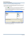
5. Choose Component from the Add menu or use the Add Component button to display
the Component Browser. Choose the Controller component and drag it over the IBD
view to add an instance column in the table. If the IBDTutor library is not visible click
Interface-Based Design Tutorial, V2013.1
December 2013
23
Interface-Based Design Tutorial
Create an Interface-Based Design View
the Add Library icon to select the IBDTutor check box in the displayed Explore Library
dialog.
6. Repeat this procedure to add the Decoder component.
7. Position the mouse over the Controller component and choose Add Signals from the
popup menu to display the Add Signals dialog box:
24
Interface-Based Design Tutorial, V2013.1
December 2013
Interface-Based Design Tutorial
Create an Interface-Based Design View
Note that the Buffer option is shown for VHDL only.
8. Click OK to confirm that you want to add signal stubs to all port types. You are warned
that the nets Clk, DataReady, Initializing, and Rst already exist.
These messages are issued because these signal nets already exist on the IBD view and
will be automatically connected by name unless you choose to create unique net names.
Note
If you are using Verilog, the dialog box includes warnings that the port and net
declarations are different for the DataReady and Initializing signals. This is because reg
outputs on the components are connected to the wire nets on the IBD view.
9. Click OK to acknowledge the warning message. Notice how the signals Clk,
DataReady, Initializing and Rst are added to the existing rows in the matrix. New rows
are added to the matrix for the additional signals required for the Controller component.
10. Repeat this process for the Decoder component. A similar warning dialog box is
displayed. If you are using Verilog, the dialog box includes warnings that the port and
net declarations are different for the signals Add, CommandValid, Multiply and Subtract.
These messages can also be ignored.
Interface-Based Design Tutorial, V2013.1
December 2013
25
Interface-Based Design Tutorial
Create an Interface-Based Design View
11. Click on the + icons to expand the Port column for each component.
12. Close the Component Browser.
13. Use the Save button to save the IBD view.
Related Topics
•
•
•
•
Add the Datapath Block
Add ModuleWare Components
Modify the ModuleWare Parameters
Add Signal Connections
Add the Datapath Block
1. Choose Block from the Add menu or use the Add Block button to add a block on the
IBD view.
2. Connect input signals to the block by clicking in the interconnect cells for input signals
A, B, Clk, Initializing, SelectInput, SelectB, AccLoad and AccAdd and selecting I from
the drop down list.
26
Interface-Based Design Tutorial, V2013.1
December 2013
Interface-Based Design Tutorial
Create an Interface-Based Design View
3. Similarly, connect output signals to the block by entering the letter O in the interconnect
cells for the two output signals Z and Multiply Done.
4. Move the cursor over the text <block> for the block instance, double-click the block to
display the Open Down Create New View Wizard.
5. Select IBD from the File Types pane in the Specify Type page and click the Next button.
Enter Datapath into the Design Unit edit box in the Specify View Name page and click
Next to display the Specify Interface page.
The port declarations on the Specify Interface page are initialized from the connections
on the parent IBD view. There should be eight input ports A, AccAdd , AccLoad, B, Clk,
Initializing, SelectB, and SelectInput plus two output ports: MultiplyDone and Z.
6. Click Finish. A new IBD view IBDTutor/Datapath/struct is created as a child view of
the Datapath block.
Interface-Based Design Tutorial, V2013.1
December 2013
27
Interface-Based Design Tutorial
Create an Interface-Based Design View
7. Use the Add Component button to display the Component Browser or choose
Component from the Add menu. Select the Counter component from the IBDTutor
library and drag it over the IBD view to add an instance column in the table.
8. Select the Counter component and choose Add Signals from the popup menu to add
stubs to the ports Clk, Initializing, AccLoad, B and MultiplyDone. You are warned that
these nets already exist. When you close the warning, the signals are implicitly
connected by name to the existing signals with the same names.
28
Interface-Based Design Tutorial, V2013.1
December 2013
Interface-Based Design Tutorial
Create an Interface-Based Design View
Add ModuleWare Components
1. Use the Add ModuleWare button to display the ModuleWare library in the Component
Browser.
2. Click on the + icon to expand the folder for the Arithmetic category and select the
Accumulator component.
3. Drag an instance of the
instance column.
Accumulator onto the DataPath IBD view to add an acc
4. Use the same procedure to select and drag a
N Bus Merge component from the Bit
Manipulation folder (added as a merge column in the IBD view) and a
N input Mux
component from the Combinatorial folder (added as a mux column in the IBD view).
Note
The new component columns are added at the right of the table but you can re-order
unexpanded component columns by dragging with the left mouse button.
5. Close the Component Browser.
Modify the ModuleWare Parameters
The N input Mux has two inputs by default but four inputs are required in this design. You can
change the number of ports available on the mux instance by using the ModuleWare Parameters
dialog box.
Interface-Based Design Tutorial, V2013.1
December 2013
29
Interface-Based Design Tutorial
Create an Interface-Based Design View
1. Select the mux column and double-click on the component to display the ModuleWare
Parameters dialog box.
2. Use the scroll control to increase the dynamic number of ports to 4.
Notice that the port widths are set to Automatic and will automatically adjust to the
width of the connected nets.
3. Click OK to close the ModuleWare Parameters dialog box.
30
Interface-Based Design Tutorial, V2013.1
December 2013
Interface-Based Design Tutorial
Create an Interface-Based Design View
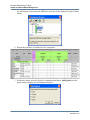
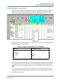
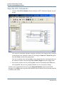
Add Signal Connections
1. Use the + icon to expand the Port column for the acc ModuleWare instance. Doubleclick in the interconnect cell for the Clk net and use the pulldown button to display a
selection list of the available formal ports as shown in the picture below.
2. Use this procedure to connect the Clk, Z, Initializing, AccLoad and AccAdd signals to the
following ports on the acc instance:
Table 1-3. Signal Connections on Acc Instance
IBD Net
ModuleWare Port
Clk
Initializing
AccLoad
AccAdd
Z
sig0
clk
rst
load
add_sub
dout
din
A new signal (sig0) must be added on the IBD view and connected to the din port.
This can be added automatically by selecting the din port in an interconnect cell for the
acc component on an empty row. However, you must edit the Bounds column for this
signal to be [4:0] if you are using Verilog or to be (4 DOWNTO 0) if you are using
VHDL.
The cin, clk_en and cout ports on the acc instance can be left unconnected as they are
not required for this tutorial and will be optimized away when HDL is generated for the
ModuleWare component.
Interface-Based Design Tutorial, V2013.1
December 2013
31
Interface-Based Design Tutorial
Create an Interface-Based Design View
Note
Note that connected signals are automatically removed from the pulldown list of
available ports unless you choose the “Show all ports” option.
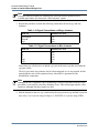
3. Repeat this procedure to make the following connections for the merge and mux
instances:
Table 1-4. Signal Connections on Merge Instance
IBD Net
ModuleWare Port
SelectInput
SelectB
sig1
din1
din0
dout
Table 1-5. Signal Connections on Mux Instance
IBD Net
ModuleWare Port
A
B
Z
sig0
sig1
din2
din3
din0
dout
sel
Notice that you will also have to add the sig1 port in the same way that you added the
sig0 port earlier.
The din1 port on the mux instance can be left unconnected as it is not required for this
tutorial and the code will be optimized away when HDL is generated for the
ModuleWare component.
Note
Although the mux component can be dynamically resized (as described in the previous
procedure), it can only be resized by multiples of two. Thus, this design requires a fourinput mux although only three inputs are used.
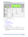
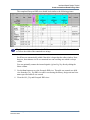
4. Edit the bounds for the new sig1 connected to the dout port on merge and the sel port on
mux to be [1:0] if you are using Verilog or (1 DOWNTO 0) if you are using VHDL.
32
Interface-Based Design Tutorial, V2013.1
December 2013
Interface-Based Design Tutorial
Create an Interface-Based Design View
The completed Datapath IBD view should look similar to the following picture:
Tip: You can choose Autofit from the Table menu to resize the width of a selected cell
or cells to the width of the contained text strings.
Scroll bars are automatically added if the table is larger than the editor window. Note
however, that columns A to E are contained in a non-scrolling area which is always
visible.
You can optionally rename the internal signals sig0 and sig1 by directly editing the
Name column.
5. Use the Save button to save the Datapath IBD view. The table was created as a child
view from the Calc_Top IBD view and is saved using the library, design unit and view
names specified when it was created.
6. Close the Calc_Top and Datapath IBD views.
Interface-Based Design Tutorial, V2013.1
December 2013
33
Interface-Based Design Tutorial
Browse the Completed Design
Browse the Completed Design
1. Select the IBDTutor library in the design explorer and choose Expand All from the
popup menu to show all components in the hierarchy.
2. Select the Calc_Top design unit and choose Show Hierarchy from the popup menu to
display the Design Hierarchy pane.
3. Select the Calc_Top design unit in the Design Hierarchy pane and choose Expand All
from the popup menu or use the + icons to expand the full hierarchy:
4. Select the Design Files node and click the IBDTutor library in the Files pane and choose
Expand All from the popup menu or use the + icons to expand the full hierarchy.
Notice that the hierarchy of the Datapath design unit includes the Counter components.
34
Interface-Based Design Tutorial, V2013.1
December 2013
Interface-Based Design Tutorial
Browse the Completed Design
You can use Change Explorer View button to view the Logical Object pane to explore
the design in detail. Refer to the “Design Browsing” chapter in the HDL Designer Series
User Manual for more information.
Now you can Generate HDL for the Hierarchy.
Generate HDL for the Hierarchy
1. Select the Calc_Top design unit in the Design Units or Design Hierarchy pane of the
design explorer window and choose the
button (or choose Run Through
Components from the Generate cascade of the Tasks menu).
The progress of the HDL generation is monitored in a log window which includes any
errors and warnings issued during generation.
If there are any errors, you can move to the next error message using the Next error
button or the previous error using the Previous error button.
You can display the source graphics corresponding to the error by double-clicking on
the error message (or by using the Cross reference to graphics button when the error is
selected).
Alternatively, you can use the Cross reference to HDL button when the error is
selected to view the generated HDL. If your text editor supports a line number argument,
the HDL line corresponding to the error is selected automatically.
Interface-Based Design Tutorial, V2013.1
December 2013
35
Interface-Based Design Tutorial
Adding the Test Bench
Adding the Test Bench
In this section, you add a test bench to test and verify that the design you have completed meets
the requirements in the specification. The test bench can be added in the same way that you
added the HDL text components which was described in “Adding the HDL Text Views” on
page 19.
1. In the Design Manager window choose File > Add > Existing Design to display the
Add Existing Design wizard.
2. Specify the method to add your design by setting the Copy Specified Files option.
3. Choose VHDL Files (if you are using VHDL) or Verilog Files (if you are using Verilog)
from the Show Files of Type pulldown filter and check the
<install_dir>\examples\tutorial_ref\Import\calculator installation subdirectory in the
Folders pane directory tree. Uncheck the Calc_text.vhd file or Calc_text.v file in the
content pane.
4. Click OK to display the Target Libraries page of the wizard.
5. Choose the IBDTutor library and click Next to display the Target Directories page.
6. Click Finish on the Target Directories page to complete the HDL addition.
The following summary report is displayed on completion:
HDL Import complete
------------------------------------------------------------1 file imported to 1 library
-------------------------------------------------------------
Notice that the Calc_tb and Calc_tester design units have been added to the IBDTutor
library in the design explorer.
7. Select the Calc_tb design unit and choose Show Hierarchy from the popup menu.
36
Interface-Based Design Tutorial, V2013.1
December 2013
Interface-Based Design Tutorial
Adding the Test Bench
Notice that the entire design (including Calc_Top and Calc_tester) can be seen by
expanding the hierarchy for Calc_tb in the Design Hierarchy pane:
A top level marker is automatically added to the Calc_tb design unit since it is not
instantiated in any other design unit.
Interface-Based Design Tutorial, V2013.1
December 2013
37
Interface-Based Design Tutorial
Setup the Downstream Tools
Setup the Downstream Tools
For this tutorial, it is assumed that ModelSim simulator and LeonardoSpectrum synthesis tools
are available. You can alternatively prepare data for use with other downstream tools.
Tip: If you have installed the HDL Designer Series tool as FPGA Advantage, the
ModelSim simulator and LeonardoSpectrum synthesis tools will already have been set up
automatically.
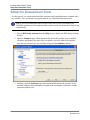
1. Choose HDS Setup Assistant from the Help menu to display the HDS Setup Assistant
Wizard.
2. Open the Simulator page which automatically detects the presence of any installed
simulators and displays the path of the executables; select the ModelSim simulator.
Note that you can specify a new simulator using the New Simulator button.
3. Similarly, open the Synthesis page which automatically detects the presence of any
installed synthesis tools and displays the path of the executables; select the Leonardo
Spectrum synthesis tool.
38
Interface-Based Design Tutorial, V2013.1
December 2013
Interface-Based Design Tutorial
Run the ModelSim Flow
Note that you can specify a new synthesis tool using the New Synthesis Tool button.
4. Click Finish.
To ensure that the downstream tools receive the correct data you should force generation and
compilation.
1. Select Set Generate Always from the Tasks menu.
2. Select Set Compile Always from the same location.
Run the ModelSim Flow
1. Select the Calc_tb design unit in the design explorer and use the
run the ModelSim flow through components.
toolbar button to
HDL is regenerated for any modified graphical views and the entire design is compiled.
The progress of the compilation is shown in the HDL Log Window.
If there are any errors, you can display the corresponding source diagram by doubleclicking on the error message as described in the section “Generate HDL for the
Hierarchy” on page 35.
Interface-Based Design Tutorial, V2013.1
December 2013
39
Interface-Based Design Tutorial
Run the ModelSim Flow
2. If generation and compilation are completed successfully, the Start Simulator dialog box
is displayed.
3. Accept the default resolution and check that the Interactive (GUI) and Enable
Communication with HDS options are selected. The other entry fields can be left in
their default state.
40
Interface-Based Design Tutorial, V2013.1
December 2013
Interface-Based Design Tutorial
Run the ModelSim Flow
4. Use the OK button to confirm the Start ModelSim dialog box and load the design.
Note that library mapping is automatically created for your downstream data.
Interface-Based Design Tutorial, V2013.1
December 2013
41
Interface-Based Design Tutorial
Run the ModelSim Flow
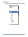
The compiled objects can be displayed in the downstream browser window of the design
manager. Select Side Data/Downstream from the SubWindows cascade of the View
menu in the design explorer and open the ModelSim tab:
42
Interface-Based Design Tutorial, V2013.1
December 2013
Interface-Based Design Tutorial
Run the LeonardoSpectrum Flow
Run the LeonardoSpectrum Flow
1. Select the Calc_Top design unit in the design explorer and use the
LeonardoSpectrum flow through components.
button to run the
Note
The tester design unit used in the test bench contains unsynthesizable HDL. Ensure that
you have selected the Calc_Top and not the Calc_tb design unit in the design explorer.
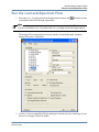
The design will be regenerated if necessary and the LeonardoSpectrum Synthesis
Settings dialog box is displayed:
2. Use the + icons to expand the FPGA technologies list and select the technology of your
choice. For example, Xilinx XC4000E.
Interface-Based Design Tutorial, V2013.1
December 2013
43
Interface-Based Design Tutorial
Run the LeonardoSpectrum Flow
Note
If you have an Exemplar level 3 license, ASIC and FPGA technology libraries are
available. If you have a level 2 license, only the FPGA libraries are available.
The Device, Speed Grade and Wire Table fields are automatically selected when you
have chosen a technology.
3. Complete the dialog box by entering a clock frequency (for example 20 MHz). All other
options can be left with their default values.
The options in the other tabs can also be left with their default values.
4. Use the OK button to confirm and close the dialog box.
When you confirm the invoke settings, LeonardoSpectrum is invoked. You might be
prompted to select an Exemplar level 1, 2 or 3 license.
Tip: Higher level licenses enable more features but you can choose to run at a lower level
using a higher level license.
When you confirm the license, your design is synthesized and optimized for the selected
technology.
The HDL files for your design are shown in the Quick Setup tab. The synthesis tool
optimizes the design for the selected technology.
44
Interface-Based Design Tutorial, V2013.1
December 2013
Interface-Based Design Tutorial
Run the LeonardoSpectrum Flow
Progress and completion messages are displayed in the information window showing
when the synthesis run has finished.
Interface-Based Design Tutorial, V2013.1
December 2013
45
Interface-Based Design Tutorial
Run the LeonardoSpectrum Flow
View the RTL Schematic
1. Click the View RTL Schematic button to display an RTL Schematic diagram for your
design.
You can move around the schematic using the scroll bars or the diagram can be enlarged
or maximized in the schematic window by choosing the Zoom In or Zoom Fit options
from the Zoom cascade of the popup menu.
You can crossprobe to the corresponding source design object by selecting an object in
the schematic window and choosing Trace to HDL Designer from the popup menu.
2. Exit from the synthesis tool by choosing Exit from the LeonardoSpectrum File menu
and respond No when you are prompted whether to save your project settings.
You have now completed this tutorial. Use the Help and Manuals option from the HDL
Designer Series Help menu to open the HDS InfoHub which contains a list of the other tutorials
available in this release.
46
Interface-Based Design Tutorial, V2013.1
December 2013
End-User License Agreement
The latest version of the End-User License Agreement is available on-line at:
www.mentor.com/eula
IMPORTANT INFORMATION
USE OF ALL SOFTWARE IS SUBJECT TO LICENSE RESTRICTIONS. CAREFULLY READ THIS LICENSE
AGREEMENT BEFORE USING THE PRODUCTS. USE OF SOFTWARE INDICATES CUSTOMER’S
COMPLETE AND UNCONDITIONAL ACCEPTANCE OF THE TERMS AND CONDITIONS SET FORTH IN
THIS AGREEMENT. ANY ADDITIONAL OR DIFFERENT PURCHASE ORDER TERMS AND CONDITIONS
SHALL NOT APPLY.
END-USER LICENSE AGREEMENT (“Agreement”)
This is a legal agreement concerning the use of Software (as defined in Section 2) and hardware (collectively “Products”)
between the company acquiring the Products (“Customer”), and the Mentor Graphics entity that issued the
corresponding quotation or, if no quotation was issued, the applicable local Mentor Graphics entity (“Mentor
Graphics”). Except for license agreements related to the subject matter of this license agreement which are physically
signed by Customer and an authorized representative of Mentor Graphics, this Agreement and the applicable quotation
contain the parties’ entire understanding relating to the subject matter and supersede all prior or contemporaneous
agreements. If Customer does not agree to these terms and conditions, promptly return or, in the case of Software
received electronically, certify destruction of Software and all accompanying items within five days after receipt of
Software and receive a full refund of any license fee paid.
1.
ORDERS, FEES AND PAYMENT.
1.1. To the extent Customer (or if agreed by Mentor Graphics, Customer’s appointed third party buying agent) places and
Mentor Graphics accepts purchase orders pursuant to this Agreement (“Order(s)”), each Order will constitute a contract
between Customer and Mentor Graphics, which shall be governed solely and exclusively by the terms and conditions of
this Agreement, any applicable addenda and the applicable quotation, whether or not these documents are referenced on the
Order. Any additional or conflicting terms and conditions appearing on an Order or presented via any electronic portal or
other automated order management system will not be effective unless agreed in writing by an authorized representative of
Customer and Mentor Graphics.
1.2. Amounts invoiced will be paid, in the currency specified on the applicable invoice, within 30 days from the date of such
invoice. Any past due invoices will be subject to the imposition of interest charges in the amount of one and one-half
percent per month or the applicable legal rate currently in effect, whichever is lower. Prices do not include freight,
insurance, customs duties, taxes or other similar charges, which Mentor Graphics will state separately in the applicable
invoice(s). Unless timely provided with a valid certificate of exemption or other evidence that items are not taxable, Mentor
Graphics will invoice Customer for all applicable taxes including, but not limited to, VAT, GST, sales tax, consumption tax
and service tax. Customer will make all payments free and clear of, and without reduction for, any withholding or other
taxes; any such taxes imposed on payments by Customer hereunder will be Customer’s sole responsibility. If Customer
appoints a third party to place purchase orders and/or make payments on Customer’s behalf, Customer shall be liable for
payment under Orders placed by such third party in the event of default.
1.3. All Products are delivered FCA factory (Incoterms 2010), freight prepaid and invoiced to Customer, except Software
delivered electronically, which shall be deemed delivered when made available to Customer for download. Mentor
Graphics retains a security interest in all Products delivered under this Agreement, to secure payment of the purchase price
of such Products, and Customer agrees to sign any documents that Mentor Graphics determines to be necessary or
convenient for use in filing or perfecting such security interest. Mentor Graphics’ delivery of Software by electronic means
is subject to Customer’s provision of both a primary and an alternate e-mail address.
2.
GRANT OF LICENSE. The software installed, downloaded, or otherwise acquired by Customer under this Agreement,
including any updates, modifications, revisions, copies, documentation and design data (“Software”) are copyrighted, trade
secret and confidential information of Mentor Graphics or its licensors, who maintain exclusive title to all Software and retain
all rights not expressly granted by this Agreement. Mentor Graphics grants to Customer, subject to payment of applicable
license fees, a nontransferable, nonexclusive license to use Software solely: (a) in machine-readable, object-code form (except
as provided in Subsection 5.2); (b) for Customer’s internal business purposes; (c) for the term of the license; and (d) on the
computer hardware and at the site authorized by Mentor Graphics. A site is restricted to a one-half mile (800 meter) radius.
Customer may have Software temporarily used by an employee for telecommuting purposes from locations other than a
Customer office, such as the employee’s residence, an airport or hotel, provided that such employee’s primary place of
employment is the site where the Software is authorized for use. Mentor Graphics’ standard policies and programs, which vary
depending on Software, license fees paid or services purchased, apply to the following: (a) relocation of Software; (b) use of
Software, which may be limited, for example, to execution of a single session by a single user on the authorized hardware or for
a restricted period of time (such limitations may be technically implemented through the use of authorization codes or similar
devices); and (c) support services provided, including eligibility to receive telephone support, updates, modifications, and
revisions. For the avoidance of doubt, if Customer provides any feedback or requests any change or enhancement to Products,
whether in the course of receiving support or consulting services, evaluating Products, performing beta testing or otherwise, any
inventions, product improvements, modifications or developments made by Mentor Graphics (at Mentor Graphics’ sole
discretion) will be the exclusive property of Mentor Graphics.
3.
ESC SOFTWARE. If Customer purchases a license to use development or prototyping tools of Mentor Graphics’ Embedded
Software Channel (“ESC”), Mentor Graphics grants to Customer a nontransferable, nonexclusive license to reproduce and
distribute executable files created using ESC compilers, including the ESC run-time libraries distributed with ESC C and C++
compiler Software that are linked into a composite program as an integral part of Customer’s compiled computer program,
provided that Customer distributes these files only in conjunction with Customer’s compiled computer program. Mentor
Graphics does NOT grant Customer any right to duplicate, incorporate or embed copies of Mentor Graphics’ real-time operating
systems or other embedded software products into Customer’s products or applications without first signing or otherwise
agreeing to a separate agreement with Mentor Graphics for such purpose.
4.
BETA CODE.
4.1. Portions or all of certain Software may contain code for experimental testing and evaluation (which may be either alpha or
beta, collectively “Beta Code”), which may not be used without Mentor Graphics’ explicit authorization. Upon Mentor
Graphics’ authorization, Mentor Graphics grants to Customer a temporary, nontransferable, nonexclusive license for
experimental use to test and evaluate the Beta Code without charge for a limited period of time specified by Mentor
Graphics. This grant and Customer’s use of the Beta Code shall not be construed as marketing or offering to sell a license
to the Beta Code, which Mentor Graphics may choose not to release commercially in any form.
4.2. If Mentor Graphics authorizes Customer to use the Beta Code, Customer agrees to evaluate and test the Beta Code under
normal conditions as directed by Mentor Graphics. Customer will contact Mentor Graphics periodically during Customer’s
use of the Beta Code to discuss any malfunctions or suggested improvements. Upon completion of Customer’s evaluation
and testing, Customer will send to Mentor Graphics a written evaluation of the Beta Code, including its strengths,
weaknesses and recommended improvements.
4.3. Customer agrees to maintain Beta Code in confidence and shall restrict access to the Beta Code, including the methods and
concepts utilized therein, solely to those employees and Customer location(s) authorized by Mentor Graphics to perform
beta testing. Customer agrees that any written evaluations and all inventions, product improvements, modifications or
developments that Mentor Graphics conceived or made during or subsequent to this Agreement, including those based
partly or wholly on Customer’s feedback, will be the exclusive property of Mentor Graphics. Mentor Graphics will have
exclusive rights, title and interest in all such property. The provisions of this Subsection 4.3 shall survive termination of
this Agreement.
5.
RESTRICTIONS ON USE.
5.1. Customer may copy Software only as reasonably necessary to support the authorized use. Each copy must include all
notices and legends embedded in Software and affixed to its medium and container as received from Mentor Graphics. All
copies shall remain the property of Mentor Graphics or its licensors. Customer shall maintain a record of the number and
primary location of all copies of Software, including copies merged with other software, and shall make those records
available to Mentor Graphics upon request. Customer shall not make Products available in any form to any person other
than Customer’s employees and on-site contractors, excluding Mentor Graphics competitors, whose job performance
requires access and who are under obligations of confidentiality. Customer shall take appropriate action to protect the
confidentiality of Products and ensure that any person permitted access does not disclose or use Products except as
permitted by this Agreement. Customer shall give Mentor Graphics written notice of any unauthorized disclosure or use of
the Products as soon as Customer becomes aware of such unauthorized disclosure or use. Except as otherwise permitted for
purposes of interoperability as specified by applicable and mandatory local law, Customer shall not reverse-assemble,
reverse-compile, reverse-engineer or in any way derive any source code from Software. Log files, data files, rule files and
script files generated by or for the Software (collectively “Files”), including without limitation files containing Standard
Verification Rule Format (“SVRF”) and Tcl Verification Format (“TVF”) which are Mentor Graphics’ proprietary
syntaxes for expressing process rules, constitute or include confidential information of Mentor Graphics. Customer may
share Files with third parties, excluding Mentor Graphics competitors, provided that the confidentiality of such Files is
protected by written agreement at least as well as Customer protects other information of a similar nature or importance,
but in any case with at least reasonable care. Customer may use Files containing SVRF or TVF only with Mentor Graphics
products. Under no circumstances shall Customer use Software or Files or allow their use for the purpose of developing,
enhancing or marketing any product that is in any way competitive with Software, or disclose to any third party the results
of, or information pertaining to, any benchmark.
5.2. If any Software or portions thereof are provided in source code form, Customer will use the source code only to correct
software errors and enhance or modify the Software for the authorized use. Customer shall not disclose or permit disclosure
of source code, in whole or in part, including any of its methods or concepts, to anyone except Customer’s employees or
on-site contractors, excluding Mentor Graphics competitors, with a need to know. Customer shall not copy or compile
source code in any manner except to support this authorized use.
5.3. Customer may not assign this Agreement or the rights and duties under it, or relocate, sublicense or otherwise transfer the
Products, whether by operation of law or otherwise (“Attempted Transfer”), without Mentor Graphics’ prior written
consent and payment of Mentor Graphics’ then-current applicable relocation and/or transfer fees. Any Attempted Transfer
without Mentor Graphics’ prior written consent shall be a material breach of this Agreement and may, at Mentor Graphics’
option, result in the immediate termination of the Agreement and/or the licenses granted under this Agreement. The terms
of this Agreement, including without limitation the licensing and assignment provisions, shall be binding upon Customer’s
permitted successors in interest and assigns.
5.4. The provisions of this Section 5 shall survive the termination of this Agreement.
6.
SUPPORT SERVICES. To the extent Customer purchases support services, Mentor Graphics will provide Customer with
updates and technical support for the Products, at the Customer site(s) for which support is purchased, in accordance with
Mentor Graphics’ then current End-User Support Terms located at http://supportnet.mentor.com/about/legal/.
7.
LIMITED WARRANTY.
7.1. Mentor Graphics warrants that during the warranty period its standard, generally supported Products, when properly
installed, will substantially conform to the functional specifications set forth in the applicable user manual. Mentor
Graphics does not warrant that Products will meet Customer’s requirements or that operation of Products will be
uninterrupted or error free. The warranty period is 90 days starting on the 15th day after delivery or upon installation,
whichever first occurs. Customer must notify Mentor Graphics in writing of any nonconformity within the warranty period.
For the avoidance of doubt, this warranty applies only to the initial shipment of Software under an Order and does not
renew or reset, for example, with the delivery of (a) Software updates or (b) authorization codes or alternate Software under
a transaction involving Software re-mix. This warranty shall not be valid if Products have been subject to misuse,
unauthorized modification, improper installation or Customer is not in compliance with this Agreement. MENTOR
GRAPHICS’ ENTIRE LIABILITY AND CUSTOMER’S EXCLUSIVE REMEDY SHALL BE, AT MENTOR
GRAPHICS’ OPTION, EITHER (A) REFUND OF THE PRICE PAID UPON RETURN OF THE PRODUCTS TO
MENTOR GRAPHICS OR (B) MODIFICATION OR REPLACEMENT OF THE PRODUCTS THAT DO NOT MEET
THIS LIMITED WARRANTY. MENTOR GRAPHICS MAKES NO WARRANTIES WITH RESPECT TO:
(A) SERVICES; (B) PRODUCTS PROVIDED AT NO CHARGE; OR (C) BETA CODE; ALL OF WHICH ARE
PROVIDED “AS IS.”
7.2. THE WARRANTIES SET FORTH IN THIS SECTION 7 ARE EXCLUSIVE. NEITHER MENTOR GRAPHICS NOR
ITS LICENSORS MAKE ANY OTHER WARRANTIES EXPRESS, IMPLIED OR STATUTORY, WITH RESPECT TO
PRODUCTS PROVIDED UNDER THIS AGREEMENT. MENTOR GRAPHICS AND ITS LICENSORS
SPECIFICALLY DISCLAIM ALL IMPLIED WARRANTIES OF MERCHANTABILITY, FITNESS FOR A
PARTICULAR PURPOSE AND NON-INFRINGEMENT OF INTELLECTUAL PROPERTY.
8.
LIMITATION OF LIABILITY. EXCEPT WHERE THIS EXCLUSION OR RESTRICTION OF LIABILITY WOULD BE
VOID OR INEFFECTIVE UNDER APPLICABLE LAW, IN NO EVENT SHALL MENTOR GRAPHICS OR ITS
LICENSORS BE LIABLE FOR INDIRECT, SPECIAL, INCIDENTAL, OR CONSEQUENTIAL DAMAGES (INCLUDING
LOST PROFITS OR SAVINGS) WHETHER BASED ON CONTRACT, TORT OR ANY OTHER LEGAL THEORY, EVEN
IF MENTOR GRAPHICS OR ITS LICENSORS HAVE BEEN ADVISED OF THE POSSIBILITY OF SUCH DAMAGES. IN
NO EVENT SHALL MENTOR GRAPHICS’ OR ITS LICENSORS’ LIABILITY UNDER THIS AGREEMENT EXCEED
THE AMOUNT RECEIVED FROM CUSTOMER FOR THE HARDWARE, SOFTWARE LICENSE OR SERVICE GIVING
RISE TO THE CLAIM. IN THE CASE WHERE NO AMOUNT WAS PAID, MENTOR GRAPHICS AND ITS LICENSORS
SHALL HAVE NO LIABILITY FOR ANY DAMAGES WHATSOEVER. THE PROVISIONS OF THIS SECTION 8 SHALL
SURVIVE THE TERMINATION OF THIS AGREEMENT.
9.
HAZARDOUS APPLICATIONS. CUSTOMER ACKNOWLEDGES IT IS SOLELY RESPONSIBLE FOR TESTING ITS
PRODUCTS USED IN APPLICATIONS WHERE THE FAILURE OR INACCURACY OF ITS PRODUCTS MIGHT
RESULT IN DEATH OR PERSONAL INJURY (“HAZARDOUS APPLICATIONS”). EXCEPT TO THE EXTENT THIS
EXCLUSION OR RESTRICTION OF LIABILITY WOULD BE VOID OR INEFFECTIVE UNDER APPLICABLE LAW, IN
NO EVENT SHALL MENTOR GRAPHICS OR ITS LICENSORS BE LIABLE FOR ANY DAMAGES RESULTING FROM
OR IN CONNECTION WITH THE USE OF MENTOR GRAPHICS PRODUCTS IN OR FOR HAZARDOUS
APPLICATIONS. THE PROVISIONS OF THIS SECTION 9 SHALL SURVIVE THE TERMINATION OF THIS
AGREEMENT.
10. INDEMNIFICATION. CUSTOMER AGREES TO INDEMNIFY AND HOLD HARMLESS MENTOR GRAPHICS AND
ITS LICENSORS FROM ANY CLAIMS, LOSS, COST, DAMAGE, EXPENSE OR LIABILITY, INCLUDING
ATTORNEYS’ FEES, ARISING OUT OF OR IN CONNECTION WITH THE USE OF MENTOR GRAPHICS PRODUCTS
IN OR FOR HAZARDOUS APPLICATIONS. THE PROVISIONS OF THIS SECTION 10 SHALL SURVIVE THE
TERMINATION OF THIS AGREEMENT.
11. INFRINGEMENT.
11.1. Mentor Graphics will defend or settle, at its option and expense, any action brought against Customer in the United States,
Canada, Japan, or member state of the European Union which alleges that any standard, generally supported Product
acquired by Customer hereunder infringes a patent or copyright or misappropriates a trade secret in such jurisdiction.
Mentor Graphics will pay costs and damages finally awarded against Customer that are attributable to such action.
Customer understands and agrees that as conditions to Mentor Graphics’ obligations under this section Customer must:
(a) notify Mentor Graphics promptly in writing of the action; (b) provide Mentor Graphics all reasonable information and
assistance to settle or defend the action; and (c) grant Mentor Graphics sole authority and control of the defense or
settlement of the action.
11.2. If a claim is made under Subsection 11.1 Mentor Graphics may, at its option and expense: (a) replace or modify the Product
so that it becomes noninfringing; (b) procure for Customer the right to continue using the Product; or (c) require the return
of the Product and refund to Customer any purchase price or license fee paid, less a reasonable allowance for use.
11.3. Mentor Graphics has no liability to Customer if the action is based upon: (a) the combination of Software or hardware with
any product not furnished by Mentor Graphics; (b) the modification of the Product other than by Mentor Graphics; (c) the
use of other than a current unaltered release of Software; (d) the use of the Product as part of an infringing process; (e) a
product that Customer makes, uses, or sells; (f) any Beta Code or Product provided at no charge; (g) any software provided
by Mentor Graphics’ licensors who do not provide such indemnification to Mentor Graphics’ customers; or
(h) infringement by Customer that is deemed willful. In the case of (h), Customer shall reimburse Mentor Graphics for its
reasonable attorney fees and other costs related to the action.
11.4. THIS SECTION 11 IS SUBJECT TO SECTION 8 ABOVE AND STATES THE ENTIRE LIABILITY OF MENTOR
GRAPHICS AND ITS LICENSORS, AND CUSTOMER’S SOLE AND EXCLUSIVE REMEDY, FOR DEFENSE,
SETTLEMENT AND DAMAGES, WITH RESPECT TO ANY ALLEGED PATENT OR COPYRIGHT
INFRINGEMENT OR TRADE SECRET MISAPPROPRIATION BY ANY PRODUCT PROVIDED UNDER THIS
AGREEMENT.
12. TERMINATION AND EFFECT OF TERMINATION.
12.1. If a Software license was provided for limited term use, such license will automatically terminate at the end of the
authorized term. Mentor Graphics may terminate this Agreement and/or any license granted under this Agreement
immediately upon written notice if Customer: (a) exceeds the scope of the license or otherwise fails to comply with the
licensing or confidentiality provisions of this Agreement, or (b) becomes insolvent, files a bankruptcy petition, institutes
proceedings for liquidation or winding up or enters into an agreement to assign its assets for the benefit of creditors. For
any other material breach of any provision of this Agreement, Mentor Graphics may terminate this Agreement and/or any
license granted under this Agreement upon 30 days written notice if Customer fails to cure the breach within the 30 day
notice period. Termination of this Agreement or any license granted hereunder will not affect Customer’s obligation to pay
for Products shipped or licenses granted prior to the termination, which amounts shall be payable immediately upon the
date of termination.
12.2. Upon termination of this Agreement, the rights and obligations of the parties shall cease except as expressly set forth in this
Agreement. Upon termination, Customer shall ensure that all use of the affected Products ceases, and shall return hardware
and either return to Mentor Graphics or destroy Software in Customer’s possession, including all copies and
documentation, and certify in writing to Mentor Graphics within ten business days of the termination date that Customer no
longer possesses any of the affected Products or copies of Software in any form.
13. EXPORT. The Products provided hereunder are subject to regulation by local laws and United States (“U.S.”) government
agencies, which prohibit export, re-export or diversion of certain products, information about the products, and direct or indirect
products thereof, to certain countries and certain persons. Customer agrees that it will not export or re-export Products in any
manner without first obtaining all necessary approval from appropriate local and U.S. government agencies. If Customer wishes
to disclose any information to Mentor Graphics that is subject to any U.S. or other applicable export restrictions, including
without limitation the U.S. International Traffic in Arms Regulations (ITAR) or special controls under the Export
Administration Regulations (EAR), Customer will notify Mentor Graphics personnel, in advance of each instance of disclosure,
that such information is subject to such export restrictions.
14. U.S. GOVERNMENT LICENSE RIGHTS. Software was developed entirely at private expense. The parties agree that all
Software is commercial computer software within the meaning of the applicable acquisition regulations. Accordingly, pursuant
to U.S. FAR 48 CFR 12.212 and DFAR 48 CFR 227.7202, use, duplication and disclosure of the Software by or for the U.S.
government or a U.S. government subcontractor is subject solely to the terms and conditions set forth in this Agreement, which
shall supersede any conflicting terms or conditions in any government order document, except for provisions which are contrary
to applicable mandatory federal laws.
15. THIRD PARTY BENEFICIARY. Mentor Graphics Corporation, Mentor Graphics (Ireland) Limited, Microsoft Corporation
and other licensors may be third party beneficiaries of this Agreement with the right to enforce the obligations set forth herein.
16. REVIEW OF LICENSE USAGE. Customer will monitor the access to and use of Software. With prior written notice and
during Customer’s normal business hours, Mentor Graphics may engage an internationally recognized accounting firm to
review Customer’s software monitoring system and records deemed relevant by the internationally recognized accounting firm
to confirm Customer’s compliance with the terms of this Agreement or U.S. or other local export laws. Such review may include
FlexNet (or successor product) report log files that Customer shall capture and provide at Mentor Graphics’ request. Customer
shall make records available in electronic format and shall fully cooperate with data gathering to support the license review.
Mentor Graphics shall bear the expense of any such review unless a material non-compliance is revealed. Mentor Graphics shall
treat as confidential information all information gained as a result of any request or review and shall only use or disclose such
information as required by law or to enforce its rights under this Agreement. The provisions of this Section 16 shall survive the
termination of this Agreement.
17. CONTROLLING LAW, JURISDICTION AND DISPUTE RESOLUTION. The owners of certain Mentor Graphics
intellectual property licensed under this Agreement are located in Ireland and the U.S. To promote consistency around the
world, disputes shall be resolved as follows: excluding conflict of laws rules, this Agreement shall be governed by and construed
under the laws of the State of Oregon, U.S., if Customer is located in North or South America, and the laws of Ireland if
Customer is located outside of North or South America. All disputes arising out of or in relation to this Agreement shall be
submitted to the exclusive jurisdiction of the courts of Portland, Oregon when the laws of Oregon apply, or Dublin, Ireland when
the laws of Ireland apply. Notwithstanding the foregoing, all disputes in Asia arising out of or in relation to this Agreement shall
be resolved by arbitration in Singapore before a single arbitrator to be appointed by the chairman of the Singapore International
Arbitration Centre (“SIAC”) to be conducted in the English language, in accordance with the Arbitration Rules of the SIAC in
effect at the time of the dispute, which rules are deemed to be incorporated by reference in this section. Nothing in this section
shall restrict Mentor Graphics’ right to bring an action (including for example a motion for injunctive relief) against Customer in
the jurisdiction where Customer’s place of business is located. The United Nations Convention on Contracts for the
International Sale of Goods does not apply to this Agreement.
18. SEVERABILITY. If any provision of this Agreement is held by a court of competent jurisdiction to be void, invalid,
unenforceable or illegal, such provision shall be severed from this Agreement and the remaining provisions will remain in full
force and effect.
19. MISCELLANEOUS. This Agreement contains the parties’ entire understanding relating to its subject matter and supersedes all
prior or contemporaneous agreements. Some Software may contain code distributed under a third party license agreement that
may provide additional rights to Customer. Please see the applicable Software documentation for details. This Agreement may
only be modified in writing, signed by an authorized representative of each party. Waiver of terms or excuse of breach must be
in writing and shall not constitute subsequent consent, waiver or excuse.
Rev. 130502, Part No. 255853