1
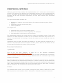
SpinetiX Technical Documentation RS232 and USB IO v2.1 Revision: 2010, March 3 © 2009 SpinetiX S.A. All rights reserved. DISCLAIMER THE SPECIFICATIONS AND INFORMATION REGARDING THE PRODUCTS IN THIS MANUAL ARE SUBJECT TO CHANGE WITHOUT NOTICE. ALL STATEMENTS, INFORMATION, AND RECOMMENDATIONS IN THIS MANUAL ARE BELIEVED TO BE ACCURATE BUT ARE PRESENTED WITHOUT WARRANTY OF ANY KIND, EXPRESS OR IMPLIED. USERS MUST TAKE FULL RESPONSIBILITY FOR THEIR APPLICATION OF ANY PRODUCTS. THE SOFTWARE LICENSE AND LIMITED WARRANTY FOR THE ACCOMPANYING PRODUCT ARE SET FORTH IN THE INFORMATION PACKET THAT IS SHIPPED WITH THE PRODUCT AND ARE INCORPORATED HEREIN BY THIS REFERENCE. IF YOU ARE UNABLE TO LOCATE THE SOFTWARE LICENSE OR LIMITED WARRANTY, CONTACT YOUR SPINETIX REPRESENTATIVE FOR A COPY. NOTWITHSTANDING ANY OTHER WARRANTY HEREIN, ALL DOCUMENT FILES AND SOFTWARE OF THESE SUPPLIERS ARE PROVIDED “AS IS” WITH ALL FAULTS. SPINETIX DISCLAIMS ALL WARRANTIES, EXPRESSED OR IMPLIED, INCLUDING, WITHOUT LIMITATION, THOSE OF MERCHANTABILITY, FITNESS FOR A PARTICULAR PURPOSE AND NONINFRINGEMENT OR ARISING FROM A COURSE OF DEALING, USAGE, OR TRADE PRACTICE. IN NO EVENT SHALL SPINETIX OR ITS SUPPLIERS BE LIABLE FOR ANY INDIRECT, SPECIAL, CONSEQUENTIAL, OR INCIDENTAL DAMAGES, INCLUDING, WITHOUT LIMITATION, LOST PROFITS OR LOSS OR DAMAGE TO DATA ARISING OUT OF THE USE OR INABILITY TO USE THIS MANUAL, EVEN IF SPINETIX OR ITS SUPPLIERS HAVE BEEN ADVISED OF THE POSSIBILITY OF SUCH DAMAGES. Hyper Media Player HMP100 User Manual v2.0 ©2009 SpinetiX S.A. All rights reserved. "SpinetiX" and “HMP Hyper Media Player” are registered trademarks, and all logo and graphic designs are trademarks of SpinetiX S.A. Other product and company names appearing in SpinetiX S.A. products and materials are used for identification purposes only and may be trademarks or registered trademarks of their respective companies. Registered and unregistered trademarks used in any SpinetiX S.A. products and materials are the exclusive property of their respective owners SpinetiX S.A. Rue des Terreaux 17 1003 Lausanne Switzerland www.spinetix.com [email protected] 2 SpinetiX Technical Documentation: Serial Port v2.1 INTRODUCTION The SpinetiX HMP100 can control external appliances using its serial port (RS232) interface or USB IOs such as the U-HID products. The RS232 of interface is supported in particular by most professional monitors to allow switch on/off operations or image configurations. The USB IOs can be used as inputs or outputs to allow the interaction between the HMP100 and external devices. To control an appliance trough the serial or the USB port interface you need the following: A protocol file for your appliance. The protocol should follow the SpinetiX proprietary syntax described in the Protocol Syntax section. Testing and debugging your protocol file can be done on a PC using the Serial Port Protocol Studio application presented in the Serial Port Protocol Studio section. The protocol file must be uploaded to the HMP100 and enabled as described in the section. When using the serial port, you need to build or purchase the serial port cable to connect your appliance to the HMP100. Special SpinetiX elements <auxCmd> need to be included into your content to control the appliance as described in the Controlling appliances section. For more information on controlling appliance with the serial port, you can check the RS232 section of the FORUM. 3 © 2009 SpinetiX S.A. All rights reserved. TABLE OF CONTENTS Disclaimer ............................................................................................................ 2 Introduction .......................................................................................................... 3 Table of Content .................................................................................................... 4 Protocol Syntax ..................................................................................................... 5 Document structure ............................................................................................ 5 <protocol> .................................................................................................... 5 <state> ......................................................................................................... 6 <in> ............................................................................................................. 6 <out> ........................................................................................................... 7 <config> ....................................................................................................... 7 Transitions ........................................................................................................ 7 <onStart> ..................................................................................................... 8 <onUpdate> .................................................................................................. 8 <onInput> ..................................................................................................... 8 <onIgnored> ................................................................................................. 9 <onDigitalInput> ............................................................................................ 9 <onAnalogInput> ..........................................................................................10 <onTimeout> ................................................................................................10 <onTest> .....................................................................................................11 <onFallback> ................................................................................................11 Actions ............................................................................................................12 <write> ........................................................................................................12 <log> ..........................................................................................................12 <setTimer> ..................................................................................................12 <resetTimer> ................................................................................................13 <set> ..........................................................................................................13 <update> .....................................................................................................13 <fire> ..........................................................................................................14 <digitalOutput>.............................................................................................14 <complete> ..................................................................................................15 Format strings ..................................................................................................15 Digital I/O support ................................................................................................16 Supported controls ............................................................................................16 Control to device port mapping ...........................................................................17 configure HMP100 IOs port ....................................................................................18 Enabling RS232 / Digital IOs ...............................................................................18 Configuring IOs .................................................................................................18 Controlling appliances ...........................................................................................20 Predefined Templates ........................................................................................20 Custom SVG syntax ...........................................................................................20 Serial Port Protocol Studio .....................................................................................22 Getting Started .................................................................................................22 Sending Commands ...........................................................................................22 Checking the files ..............................................................................................23 Serial cable ..........................................................................................................26 Warning: ..........................................................................................................26 4 SpinetiX Technical Documentation: Serial Port v2.1 PROTOCOL SYNTAX COM port protocol files contain the implementation of a serial port communication protocol. This protocol file describes the relationship between the action generated from (or to) the player and the strings sent on the serial port cable. This implementation is described as an XML document representing a finite state machine and associated transitions. The inputs to this state machine are: Requests to initiate a new control action, for instance request to power off the display; Characters received on the serial port; Timer expirations. The outputs are: Characters sent out to the controlled device. Actions for interactivity content trigged by the serial port Logs depending on the input on the serial port. The relationship between the inputs and the output is described using a finite state machine. The XML description is made of a list of states. Each state may have a list of actions to be performed on entering or leaving the state and must contain at least one transition. Transitions from one state to another are based on an input and may contain a list of actions to be performed when the transition is taken, that is after the out actions for the current state and before the actions of the new state. Document structure <protocol> This is the top level element; it must be in the SpinetiX namespace (http://www.spinetix.com/namespace/1.0/spx). The mandatory 'target' attribute specifies the type of target controlled by this protocol, such as 'monitor'. It must match the target attribute from the <auxCmd> tag in SVG content on the player. The optional 'startup' and 'start' attributes may override the name of the two mandatory states, respectively the state that the machine is in when it starts up and the state from which new commands are dispatched. By default the names are respectively 'startup' and 'start'. Start command transitions can only be processed from the 'start' state. A 'startup' state is mandatory, but it may be the same as the 'start' state. Example: The example below shows a very simple protocol file which sends a 'PWR OFF' or 'PWR ON' string to the serial interface when a 'PowerOff' or 'PowerOn' command is received. 5 © 2009 SpinetiX S.A. All rights reserved. <protocol target='monitor' startup='start' xmlns='http://www.spinetix.com/namespace/1.0/spx'> <state xml:id='start'> <onStart command='PowerOff'> <write data='PWR OFF
' /> </onStart> <onStart command='PowerOn'> <write data='PWR ON
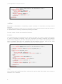
' /> </onStart> </state> </protocol> <state> Each state is described in a matching <state> element. It must have a unique xml:id attribute. A state may contain at most one <in> and one <out> element that are lists of actions to be performed on entering, respectively leaving, the state. It must contain at least one transition element. Example: The example below is composed of two states. The first one ('start') waits to the player to send a 'PowerOff' command. Once this command has been received, the machine moves to the 'do_power_off' state. The string 'KK 00 01\r' is send to the serial port and a timer is trigged. There are two possibility for the machine to move back to the initial state, either when the 'OK\r' is received or when the timer expires. <protocol target='monitor' startup='start' xmlns='http://www.spinetix.com/namespace/1.0/spx'> <state xml:id='start'> <onStart command='PowerOff' goto='do_power_off' /> </state> <state xml:id='do_power_off'> <in> <write data='KX 00 01
' /> <setTimer timer='RxTimeout' expiration='500ms' /> </in> <out> <resetTimer timer='RxTimeout' /> </out> <onInput match='OK
' goto='start'> <complete status='success' /> </onInput> <onTimeout timer='RxTimeout' goto='start'> <complete status='failure' /> </onTimeout> </state> </protocol> <in> List of actions to be performed when entering the parent state. Each state may contain at most one <in> element. 6 SpinetiX Technical Documentation: Serial Port v2.1 Example: <state xml:id='action'> <in> <log level='info' message='Entering state action' /> </in> [...] </state> <out> List of actions to be performed when leaving the parent state. Each state may contain at most one <out> element. Example: <state xml:id='action'> [...] <out> <log level='info' message='Leaving state action' /> </out> </state> <config> This section contains a list of parameters (global variables) that should be set before start up according to user provided configuration. Each parameter is described in a <param> element with the following attributes: name: variable name value: default value type: variable type, either 'int', 'number' or 'string'. This works as an indication of possible values for the user. desc: user readable description of what this parameter is. Example: <config> <param name='id' value='0' type='int' desc='Monitor ID' /> </config> Transitions Transition elements are used to make the finite state machine go from one state to another. The following transitions are supported: <onStart>, <onUpdate>, <onInput>, <onIgnored>, <onDigitalInput>, <onAnalogInput>, <onTimeout>, <onTest> and <onFallback>. 7 © 2009 SpinetiX S.A. All rights reserved. All transition elements take a 'goto' attribute which specifies the id of the target state to transition to. It may be omitted in which case the transition is reflective to the same state, and neither the in nor out actions list are triggered. goto = "<state-id>" Id of the target state of the transition. If omitted the transition is reflective to the same state. <onStart> command = "<string>" Name of the action triggered by the <auxCmd> tag inside SVG content Change state on receiving a request from the user to start a new command. This is triggered by an <auxCmd> tag inside SVG content with a matching 'command' attribute. These are only valid in the 'start' state. Parameters was passed in the command are available in the variables $PARAM1, $PARAM2, ... Example: <onStart command='PowerOn' goto='transmit_power_on' /> <onUpdate> name = "<shared variable>" Name of the shared variable triggering the change of state. Change state when a shared variable is updated. This transition is only valid in the 'start' state. The name of the variable, its value and the timestamp are available in the special variables $NAME, $VALUE and $TIMESTAMP respectively. The timestamp is in second since Jan 1st, 1970 UTC Example: <onUpdate name='temp@thermometer' goto='temp_change' /> <onInput> match = "<string>" Regular expression to be matched. data = "<string>" Literal string to be matched. The change of state is based on new input characters. The 'match' attribute contains a regular expression that is matched against the input stream. It may be as simple as one character. Multiple characters are interpreted as the sequence to be received in the order 8 SpinetiX Technical Documentation: Serial Port v2.1 specified and starting at the first character (it will not match inside the input). For instance the match string 'abc' will match 'abcx' (x is retained in the input buffer for later matches), but it won't match xabc because the start character does not match. In the same example, if 'abx' is received, the transition is not taken, but both 'a' and 'b' are "eaten" (taken out of the receive buffer) as a mismatch is detected only when receiving the 'x'. The match string may contain the following special characters: Character ranges, specified inside brackets: o [a-z] matches any characters from the ascii code of 'a' to the code of 'z'. Use [0-9] to match a digit. o [abc] matches any of 'a', 'b' or 'c' o multiple ranges are allowed, e.g. [a-zA-Z] o use [a-] to match either 'a' or '-' The '*' to match a repetition of 0 or more of the previous character or character range. The '?' to optionally match the previous character or range. The '\' to escape a special character so that is interpreted literally. Use '\\' for the backslash itself. A pair of parenthesis around characters inside the match expression will allow this sequence to be stored inside the special $n variable when the transition is taken. Some example match strings: "OK [0-9][0-9]
" matches a line starting with 'O' 'K', followed by digits and the <CR> <LF> terminators "ERROR ([1-9][0-9]*)
" matched a line with 'E' 'R' 'R' 'O' 'R' ' ' and a number with one or more digits whose value is stored in the $1 variable. Alternatively, a 'data' attribute instead of 'match' will do a literal match for all characters (no regular expression). Example: <onInput data="L" goto="L_input" /> <onInput match="OK [0-9][0-9]
" goto="ok_state" /> <onIgnored> Change state when an input character is not matched by any other rule. Note that if no 'goto' attribute is given it will stay within the same state but avoid outputting warning messages about ignored characters. Example: <onIgnored goto="start" /> <onDigitalInput> device = "<number>" Device number of the digital input line. port = "<number>" 9 © 2009 SpinetiX S.A. All rights reserved. Port number of the digital input line. action = "open|close|<unspecified>" Type of action that will trigger the transition. Change state when a digital input state changes. The 'device' and 'port' attributes are used to filter respectively on the device number and port number of the digital input line. If unspecified any line changing state will trigger the transition. The 'action' attribute is either 'open', 'close' or unspecified. If unspecified both changes will trigger the transition. The device number, port number and new state are available in the special variables $IODEVICE, $IOPORT and $IOVAL respectively. $IOVAL will be 1 for 'close' and 0 for 'open'. If such no transition is available that will match a digital input line change on the current state, the change is remembered and may be matched in any state thereafter. This can be useful to, for instance, only check the digital input lines in the start state. Example: <onDigitalINput device='1' port='1' action='close' goto="sensor_close" /> <onAnalogInput> device = "<number>" Device number of the analog input line. port = "<number>" Port number of the analog input line. Change state when an analog input state changes. The 'device' and 'port' attributes are used to filter respectively on the device number and port number of the analog input line. If unspecified any line changing level will trigger the transition. The device number, port number and new input level are available in the special variables $IODEVICE, $IOPORT and $IOVAL respectively. If such no transition is available that will match the analog input line change on the current state, the change is remembered and may be matched in any state thereafter. This can be useful to, for instance, only check the analog input lines in the start state. Example: <onAnalogINput device='1' port='1' goto="temperature_changed" /> <onTimeout> timer = "<timer-name>" Name of the timer triggering the change of state. 10 SpinetiX Technical Documentation: Serial Port v2.1 Change state when a timer expires. The timer name is in the 'timer' attribute. Timers are created by the <setTimer> action. Example: <onTimeout timer='RxTimeout' goto='rx_timeout' /> <onTest> var = "<variable-name>" Name of the variable to test. stringEqualTo = "<string>" Check that the variable is equal to the given string. stringNotEqualTo = "<string>" Check that the variable is not equal to the given string. numberEqualTo = "<number>" Check that the variable is equal to the given number. numberNotEqualTo = "<number>" Check that the variable is not equal to the given number. numberLessThan = "<number>" Check that the variable is less than the given number. numberLessThanOrEqual = "<number>" Check that the variable is less or equal to the given number. numberGreaterThan = "<number>" Check that the variable is greater than the given number. numberGreaterThanOrEqual = "<number>" Check that the variable is greater or equal to the given number. Change state based on the content of a variable. The 'var' attribute specifies the variable name. One of the following comparators specifies the value to test for: stringEqualTo, stringNotEqualTo, numberEqualTo, numberNotEqualTo, numberLessThan, numberLessThanOrEqual, numberGreaterThan, numberGreaterThanOrEqual. Example: <onTest var='RetryCount' numberLessThan='3' goto='retry' /> <onTest var='DeviceId' stringEqualTo='HMP100' goto='new_device' > <onFallback> Unconditional transition to a new state. Typically for a "catch all" type of condition. As all transitions are evaluated in the order specified in the XML description, it should typically the last element of the list of possible transitions. 11 © 2009 SpinetiX S.A. All rights reserved. Example: <onTest var='input' stringEqualTo='VGA' goto='select_vga' /> <onTest var='input' stringEqualTo='DVI' goto='select_dvi' /> <onFallback goto='select_other' /> Actions Each time the finite state machine changes state, it is possible to specify actions to be executed. The actions may be specified for each transition described in the previous section. As a special case, a list of action may also be specified in the <in> and <out> tags directly under <state>. <write> data = "<string>" Write the given string to the serial interface. Send out some characters on the serial port, as specified by the 'data' attribute. Example: <write data='KX 00 01
' /> <log> mesage = "<string>" Write the given string in the log file. level = "trace|debug|info|warning|error" Logging level of the string. Add an entry to the system log. The 'level' attribute is mandatory; it must be one of 'debug', 'trace', 'info', 'warning' or 'error'. The 'message' attribute contains the log message. Example: <log level='info' message='Monitor is powered off' /> <setTimer> timer = "<timer-name>" Name of the timer to be created. expiration = "<time in sec>" Duration in seconds of the timer period = "<time in sec>" Repetition time of the timer 12 SpinetiX Technical Documentation: Serial Port v2.1 Start a single shot or periodic timer. The 'timer' attribute specifies a reference name for the timer used to associate with <onTimeout> transitions. For a single shot timeout, use the 'expiration' attribute with a time in seconds postfixed by 's' or a time in milliseconds postfixed by 'ms'. This selects the expiration date as a relative time. For a periodic timer, the 'expiration' attribute specifies the first expiration and the 'period' attribute specifies how often the timer will expire . In effect, each time the timer expires, it is reset to the value of the 'period' attribute. Examples: <setTimer timer='RxTimeout' expiration='100ms' /> <setTimer timer='PeriodicCheck' expiration='0' period='60s' /> <resetTimer> timer = "<timer-name>" Name of the timer to be reset. Cancel a timer previously setup by <setTimer>. The 'timer' attribute must match the reference name of a previously set timer. Example: <resetTimer timer='RxTimeout' /> <set> var = "<variable-name>" Name of the variable to be set. to = "<string>|<number>" Value of the variable to set. Change the value of a variable. The variable name is specified by the 'var' attribute, the new value is in the 'to' attribute. Example: <set var='Data' to='30' /> <update> name = "<shared variable>" Name of the shared variable to be modified. value = "<string>|<number>" Value of the shared variable. time = "<UTC timestamp>" 13 © 2009 SpinetiX S.A. All rights reserved. Optional value of the time at which the variable should be modified. Update the value of a shared variable. The name is specified by the 'name' attribute and the new value by the 'value' attribute. The shared variable may local ('MyVariable') or remote ('MyVariable@MyServer'). The optional 'time' attribute may be used to specify a UTC timestamp for the update (in seconds since Jan 1st, 1970). Example: <update name='weather' value='sunny' /> <fire> event = "mousedown|mouseup|mousemove|mousewheel| keydown|keyup|keystate|textInput|focusin|focusout" Name of the event to be triggered. time = "<UTC timestamp>" Optional value of the time at which the event should be fired. Send a UI trigger to the SVG document. The event type is specified by the 'event' attribute. The optional 'time' attribute may be used to specify a UTC timestamp for the event (in seconds since Jan 1st, 1970). The following attribute are required according to the event type: mousedown, mouseup: 'x' , 'y' and 'button' mousemove: 'x' and 'y' mousewheel: 'x', 'y', and 'delta' keydown, keyup: 'key' and 'keystate' (optional bit mask) textInput: 'data' focusin, focusout: no attribute required Example: <fire event='mousedown' x='45' y='20' button='0' /> <fire event='keydown' key='Enter' /> <fire event='keydown' key='A' /> <digitalOutput> device = "<number>" Device number of the digital input line. port = "<number>" Port number of the digital input line. action = "open|close Action to be performed on the given IO. 14 SpinetiX Technical Documentation: Serial Port v2.1 Set the state of the digital output line identifed by the 'device' and 'port' attributes. The 'action' attribute must be either 'open' or 'close'. Example: <digitalOutput device='1' port='1' action='open' /> <complete> status = "success|failure" Status of the current command. Signal the completion of the current command. The mandatory 'status' attribute should be set to 'success' if the command was successful, otherwise it should be set to 'failure'. Example: <complete status='success' /> Format strings The 'data', 'to', 'message' and 'match' attribute values may be formatted according to the content of some variables by using a format string. The string formatting facility is based on the C language "printf" format specification strings where the '%' character is replaced by the value of a variable. The '%' should be followed by a format specification character and a variable name between curly braces for string values or a numerical expression for integer or floating point values. Numerical expression are basically composed of variable names, numbers and the '+', '-', '*' and '/', operators with usual priorities and meaning and the possibility to use parenthesis for grouping. For example: <write data='KX %02x{id}
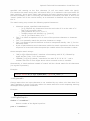
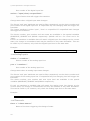
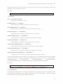
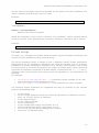
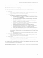
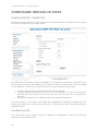
' /> formats the integer variable 'id' as a two digit hexadecimal number padded with zero. <set var='Count' to='%d{Count+1}'/> will increment the 'Count' variable. The following format characters are supported and may be prefixed by the relevant precision and padding flags: %s for strings %c for a single character where the numerical expression is evaluated to an ascii code, e.g. %c{65} for the 'A' character. %d for signed integer %u for unsigned integer %o for octal integer %x for hexadecimal integer using letters 'a' to 'f' %X for hexadecimal integer using letters 'A' to 'F' %f, %e %E, %g and %G for floating point numbers %% is the '%' character itself. 15 © 2009 SpinetiX S.A. All rights reserved. DIGITAL I/O SUPPORT Digital I/O on HMP100 supports any USB HID. This allows to generically support a wide array of I/O devices and applications. Each USB interface exposed by a USB physical device is considered as an independent I/O device by the HMP100. Only I/O devices which have non-ignored controls are left open, the others are ignored. The HMP100 will periodically rescan the bus for device removal or insertion. After a settle period the I/O devices are renumbered with consecutive numbers starting at 1. Numbering depends on USB device IDs and should thus be stable across reboots if no new USB HID devices are removed or inserted. However, USB devices which are identical and which have the same name or no serial number cannot be reliably distinguished. In such situations numbering should depend on USB plug location in the USB hub although it may be unstable. See the HID and HID Usage Tables specifications for details on HID, available at http://www.usb.org/developers/hidpage. Supported controls The following HID controls are ignored by the HMP100: all constant fields are ignored (typically used for padding in HID reports) all HID controls (input or output) under a mouse, keyboard, keypad or system control application collection are ignored; this avoids conflicts with keyboards and mice which are handled as input events to the SVG DOM. all HID controls which are not under one of the following HID application collections are ignored o Generic Desktop Controls o Simulation Controls o Game Controls feature HID controls are not supported and thus ignored The HMP100 uses the following rules to decide whether the input is analog or digital: any HID input control which has a usage in the button page of the HID usage tables spec or has a logical min-max range of 1 is considered as a digital input; the minimum value is reported as "open" (0) and any other value is reported as "closed" (1). all other HID input controls are considered analog inputs, no normalization is done on the values, the raw logical values are reported The HMP100 uses the following rules to decide whether an output is analog or digital: 16 any HID output control which has a usage in the button page of the HID usage tables spec or has a logical min-max range of 1 is considered as a digital output; the "open" (0) value is sent to the device as the minimum logical value, the "closed" (1) value is sent as the minimum + 1. all other HID output controls are considered analog outputs, no normalization is done on the values, the values are sent as the raw logical values SpinetiX Technical Documentation: Serial Port v2.1 I/O devices which have all HID controls ignored are completely skipped and have no associated device number. Control to device port mapping The HMP maps the HID controls of each I/O device to port numbers as follows: Digital input o Each control is assigned a sequential port number, starting at one, in the order of appearance in the HID report descriptor Analog input o Controls which are recognized as Microsoft DirectInput Joystick controls are mapped in the same way as in DirectInput. The first of each X, Y, Z, RX, RY or RZ axis is assigned port number 1, 2, 3, 4, 5 or 6, respectively The first of each slider and dial are assigned to ports 7 and 8 (the two sliders in DirectInput's Joystick), in order of appearance in the HID report descriptor The wheel is assigned port number 3 (the Z axis in DirectInput's Joystick), if that port is not already assigned The steering is assigned port number 1 (the X axis in DirectInput's Joystick), if that port is not already assigned The accelerator is assigned port number 2 (the Y axis in DirectInput's Joystick), if that port is not already assigned The rudder and brake are assigned port number 6 (the RZ axis in DirectInput's Joystick), if that port is not already assigned The throttle is assigned port 7, if not already assigned, otherwise 8 if that port is not already assigned o All other controls, or controls above which could not be assigned the port because it is already assigned to another control, are assigned sequential port numbers, starting at 128, in the order of appearance in the HID report descriptor Controls assigned to this range may change port number in future releases of the firmware Digital output o Each control is assigned a sequential port number, starting at one, in the order of appearance in the HID report descriptor Analog output o Each control is assigned a sequential port number, starting at one, in the order of appearance in the HID report descriptor o Analog outputs are currently only listed, the firmware has currently no support for manipulating analog outputs The mapping of HID controls to ports is output to the HMP player logs each time a new I/O device is enumerated to aid in diagnosing. Note that digital / analog and input / output have all separate port numbering spaces within the same I/O device. 17 © 2009 SpinetiX S.A. All rights reserved. CONFIGURE HMP100 IO PORT Enabling RS232 / Digital IOs Enabling the IOs support is done using the HTTP administration interface and the Serial Port menu as shown in the image below. By default the serial port control is disabled. It is enabled by selecting a protocol file in the Protocols drop-box. By default only a limited number of protocol files are pre-loaded on the HMP100. To add a new protocol for your screen follow the step below: Create a protocol file as described in the previous section Use the Upload Protocol File to store it on the HMP100. You can store as many protocol file as you wish on the device but only one of them can be activated at the time. Select the protocol file you want to use in the Protocols drop box. You can choose to use either pre-loaded files designed by SpinetiX (identified by the prefix [sys] before the name of the protocol), or files that you have uploaded using the Upload function. Configuring IOs The drop down menu below shows an HMP100‟s configuration where the following protocol files can be selected: 18 SpinetiX Technical Documentation: Serial Port v2.1 No protocol files, the RS232 interface is disabled ([disabled]) A system version of the Sharp Aquos protocol ([sys]sharp_aquos) An uploaded protocol file for the LG LF65 screen (LG LF65) An uploaded protocol file for the Sharp Aquos monitors (sharp_aquos) Once a protocol file is selected, you might choose to change the serial port configuration or to enable automatic power on and power off of the attached screen. Checking the Control monitor power check box will force the HMP100 to send the PowerOn and PowerOff commands at specified times (in 24 hours format) regardless of the content uploaded on the device. In the example below the HMP100 has been configured to use the LG LF65 protocol, and automatically turn the screen ON at 8:00 and OFF at 20:00. If you want to have a finer controls on the actions performed by the HMP100 on the serial port, you need to used serial port command in your hyper media project. This procedure is explained in more details in the next section. 19 © 2009 SpinetiX S.A. All rights reserved. CONTROLLING APPLIANCES Predefined Templates HMD comes with a set of predefined documents for sending commands on the serial port. Those templates can be found under MyTemplates/SerialPort/. These files can then be used in any multi-layer, playlist document or schedule document. The following templates are provided: Mute with the configurable On/Off option. Let you turn on and off the audio of the monitor. The protocol must understand the MuteOn and MuteOff command. Power with the configurable On/Off option. Let you turn on and off the monitor. The protocol must understand the PowerOn and PowerOff command. Source with configurable destination. The protocol must understand some or all off the following commands: HDMI1, HMDM2, VGA, AV1, AV2, AV3. Volume with a configurable level (between 0 and 100). The protocol must understand the SetVolume command with a parameters for the volume. Custom SVG syntax Sending command to appliances connected to the HMP100 using the RS232 connection is done using the <auxCmd> element. The <auxCmd> uses the following attributes: target = ”target”: (mandatory) Type of target to control. It must match the target of the protocol file. command = ”command” (mandatory) Name of the command to execute. It must match one of the command attribute of the <OnStart> element of the protocol file. param1 (to param9) = “parameters” (optional) Optional parameters. It is a string, a number or a regular expression. The content of the parameter paramX will be stored in $PARAMX when executing the fsm file. begin = "begin-value-list": (optional, =‟0‟ if not present) See http://www.w3.org/TR/SVGMobile12/animate.html#TimingAttributes for more information about the begin attribute. 20 SpinetiX Technical Documentation: Serial Port v2.1 It is possible to animate the attribute of the <auxCmd> like any other media element. Example: <auxCmd <auxCmd <auxCmd <auxCmd target="monitor" target="monitor" target="monitor" target="monitor" command="PowerOn"/> command="PowerOn" begin="5s" /> command="SetVolume" param1="30"/> command="SelectInput" param1="AV1"/> It is recommended to use a complete file to execute RS232 command. 21 © 2009 SpinetiX S.A. All rights reserved. SERIAL PORT PROTOCOL STUDIO The SPP Studio application lets you check your protocol files from a PC connected to your appliance (monitor for instance). This should help you in debugging the protocol files and check that the appliance behaves as expected. The SSP Studio lets you test protocol files. To edit your protocol files you will need an external XML editor. Getting Started In order to work with your protocol files you need to perform the following operations: Make sure that your RS232 port settings are correct. The Settings button is used to configure the speed and the various options for the transmission on the RS232 port. The default settings should work with most appliances. Open you protocol file using the Open button. Start the finite state machine using the Run button. Now SPP Studio is ready to send commands to your appliance. Sending Commands Depending on your protocol files, a different set of command will be shown in the SPP Studio interface. SPP Studio will add a command button for each <onStart> elements of start state of your protocol file. For instance the following file: <state xml:id='start' desc='Start command'> <onStart command='PowerOn' goto='transmit_poweron' /> 22 SpinetiX Technical Documentation: Serial Port v2.1 <onStart command='PowerOff' goto='transmit_poweroff' /> <onStart command='MuteOn' goto='transmit_muteon' /> <onStart command='MuteOff' goto='transmit_muteoff' /> <onStart command='SelectInput' goto='select_input_start'> <set var='Input' to='$PARAM1'/> </onStart> <onStart command='SetVolume' goto='transmit_vol'> <set var='Volume' to='%d{$PARAM1*60/100}'/> </onStart> </state> It will lead to the following set of commands visible on the SPP Studio. Pressing any button is equivalent to sending the command using the <auxCmd> on the HMP100. For instance: The PowerOn button is equivalent to the execution of an SVG file including the element <auxCmd target="monitor" command="PowerOn"/> The SetVolume button with a value of 50 in the first parameters text box is equivalent to the execution of an SVG file including the element <auxCmd target="monitor" command="SetVolume" param1="50"/> Checking the files With SPP Studio you can see the characters which are sent and received on the RS232 interface. The Dialog between the PC and the appliance is shown just under the parameters input. The characters sent to the appliance are shown in blue. The characters sent from the appliance are shown in italic black. Non-printable characters are shown using their character code, i.e. 
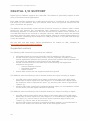
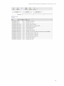
 means characters 13, end of line (\n). As an example, let us use the protocol file of example A in the annexes: The example below shows the dialog between the PC and a Sharp Aquaos when the user presses the MuteOn, MuteOff and SetVolume button (with an input of 50 for the volume). The mute on command is sent (MUTE0001\n), and the screen replies that the settings have been modified as expected (OK\n). The mute off command is sent (MUTE0002\n), and the screen replies that the settings have been modified as expected (OK\n). 23 © 2009 SpinetiX S.A. All rights reserved. The volume command is sent (VOL0030\n), and the screen replies that the settings have been modified as expected (OK\n). Note that the Sharp Aquos expects a volume between 0 and 60, whereas we have defined in the protocol file that the volume was between 0 and 100. Thus the value of 50 has to be converted to 30 when sent to the screen using the set command in the protocol file: <set var='Data' to='%d{$PARAM1*60/100}'/> It is possible to increase the logging level of the finite state machine to indicate exactly what is happening during the exchange. To do so, change the Log Level to Debug. The debugging mode will indicate all the steps taken by the finite state machine to send and receive information from/to the appliance. For instance the effect of the MuteOn command using the example A protocol file is shown in the example below. 24 The finite state machine starts with the state „start‟ The command MuteOn is received The variables „Command‟ and „Data‟ are set respectively to „MUTE‟ and „1‟ The FSM moves to the state transmit and sends the „MUTE001\n‟ characters. The FSM receives „OK\n‟ from the screen and thus moves from the „transmit‟ state back to the „start‟ state, ready to receive new commands. SpinetiX Technical Documentation: Serial Port v2.1 25 © 2009 SpinetiX S.A. All rights reserved. SERIAL CABLE To connect the HMP100 to an RS232 appliance you will need a special cable. The cable can ordered from SpinetiX at the following address: http://www.spinetix.com/store The serial cable‟s connections are given below. Warning: Do not plug or unplug the RS232 cable from the HMP100 when the HMP100 is turned on. This might cause irreversible damage to the HMP100 and/or the device connected on the other side of the cable. 26