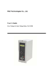
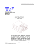
1
Polymer Insulated Fault Interrupters for 25 .8kV Overhead Line
User’s Manual
2010.8 V1.0
ENTEC ELECTRIC&ELECTRONIC CO., LTD
78-2 Buncheon-ri Bongdam-eup Hwaseong-city Gyunggi-do Korea 445-894
TEL :(031)227-1161 FAX : (031)227-1164
[텍스트 입력]
Polymer Insulated Fault Interrupters for 2 5 .8kV Overhead Line
2
[텍스트 입력]
Polymer Insulated Fault Interrupters for 2 5 .8kV Overhead Line
<CONTENTS>
1. Introduction --------------------------------------------------------------------------------------------4
2. Rating and Specification ------------------------------------------------------------------------4
3. Function and Characteristic ------------------------------------------------------------------5
4. Control Box Setting --------------------------------------------------------------------------------7
5. Pickup description, function test, operation method ----------------------------7
6. Name and Description -------------------------------------------------------------------------- 10
7. Unpacking and Handling --------------------------------------------------------------------- 21
8. Installation -------------------------------------------------------------------------------------------- 21
9. Check and Maintenance----------------------------------------------------------------------- 22
10. Installation Drawing--------------------------------------------------------------------------- 24
11. Circuit Diagram --------------------------------------------------------------------------------- 25
3
[텍스트 입력]
Polymer Insulated Fault Interrupters for 2 5 .8kV Overhead Line
1. Introduction
This is installed on feeder, wire or service entrance of consumer, in the branch point of below 16MVA
load capacity. When over load or fault is occurred, it minimizes the damage and prevents the fault
expansion by opening only the fault section with the cooperation of upstream protection equipment
(CB, Recloser). Easy operation status monitoring is available by built-in load current indicator and
live line status indication.
2. Rating and Specification
ITEM
Condition
RATING
-25 ℃ ∼ 40 ℃
Ambient temperature
Altitude
Rated voltage [kV]
Rated current [A]
Rated frequency [Hz]
Fast
Rated short time
1 sec.
current
10 sec.
Rated making current
Rated breaking current
dry
Power frequency
withstand voltage
wet
Below 1,000 M
25.8
400
60
15 kA
12.5 kA
3.5 kA
32.5kA (Peak)
12.5 kA(r.m.s)
60 kV / 1 min.
50 kV / 10 sec.
150 kV
Impulse withstand voltage (1.2×50㎲)
Min. pickup
current
Control Power
PHASE
OFF, 50 ~ 630 A(Block), 5A Step
GROUND
Cold Load Pickup
OFF, 25 ~ 315 A(By Pass), 5A Step
0.0 ~ 5.0 sec. ( ±10% ), 0.1 sec. Step
DC 24 V (12V7AH*2EA)
50 times or 24 hour (fully charged)
AC 220 V / 25 VA, Max.200 VA
2kV/1min
Voltage waveform:6kV,1.2/50μs Current
waveform:3kA,8/20μs
EFT/BURST test: 4 kV(2.5 Hz)
Oscillatory SWC test: 2.5 kV(1 MHz)
Battery
External power
Power frequency withstand voltage
Control box
internal ambient
test
Impulse withstand voltage
Surge Withstand Capability
Radiated electromagnetic
interference withstand test
IEEE C37.90.2 35V/m
4
[텍스트 입력]
Polymer Insulated Fault Interrupters for 2 5 .8kV Overhead Line
3. Function and Characteristic
When the fault current higher than Min. pickup current flows, automatic breaking is available
according to the T-C Curve and if the upstream protection equipment is opened first it is spring
charged regardless the T-C Curve. This is used for frequent lightning place, industrial line. the
following functions are provided.
3.1. Over-current Trip function
This interrupter detects over-current and separates the fault section from the system when the
upstream device protection equipment is opening the line. Besides, detects over-current and
cooperates with the upstream protection equipment. OCR Trip, OCGR Trip function is provided.
3.2. Cold Load Pickup function
Restrain the over-current Trip function and charge Trip function to prevent the malfunction by
inrush current produced during the closing or when becomes live line by upstream protection
equipment closing from dead line status.
After the interrupter is opened, if the interrupter is closed exceeding the 'Outage Time', this
function is not operated, if the interrupter is closed after the 'Outage Time' this functions operates
normally. Under the Interrupter closed condition, the line becomes dead line by upstream
protection equipment and if the line becomes live line by reclosing within 'Outage Time' the Cold
Load Pickup function does not operate.
< Figure 3-1> Cold Load Pickup function Operation condition in case of interrupter closing
5
[텍스트 입력]
Polymer Insulated Fault Interrupters for 2 5 .8kV Overhead Line
< Table 3-2 > Cold Load Pickup function condition in case of Dead line status to Live line status
3.3. Line current and Live line indication
Each phase currents (A,B,C,N) are displayed on LCD of control box and Lamp that indicates the
line status of source side (phase A) is provided.
3.4. Easy function setting
Min. pickup current, over-current lock current and other all setting can be set in LCD menu of
control box.
3.5. Battery discharge prevention
Blocks automatically before the over-discharge of battery by AC power loss and prevents the
damage. When AC power is applied, it returns to the normal operation.
6
[텍스트 입력]
Polymer Insulated Fault Interrupters for 2 5 .8kV Overhead Line
4. Control Setting
The setting method of Interruptor control is the same as following.
4.1. Minimum Pickup Current
Easy Min. pickup current setting is available through control LCD menu.
4.1.1. PHASE Min. Pickup Current Setting
PHASE Min. Pickup Current is 2~3 times of Max. Load Current.
Contract ( kW )
22 .9( kV ) × 3
× ( 2 ~ 3 times ) = PHASE Min . Pickup Current
4.1.2. GROUND Min. Pickup Current Setting
Malfunction can be caused if Unbalance rate of three phase is big and GROUND Min. Pickup
Current is smaller than Load Current. Therefore, GROUND Min. Pickup Current shall be set in
50% of PHASE Min. Pickup Current.
4.2. Cold Load Pickup Setting
Inrush Time and Outage Time can be set easily in LCD menu of control. Default value of Inrush
time is 0.5 sec. and Default value of Outage Time is 3.0sec.
5. Operation description, function test, operation method
5.1. Operation description
5.1.1. When the fault current is over than Min. pickup current the upstream protection device
does the delay operation, mostly the fault is removed directly by the interrupter because the
CONTROL RESPONSE TIME of interrupter is fast. Sometimes the upstream protection
equipment removes the fault depending on its setting.
5.2. Operation function test
This interrupter is set and tested completely before the delivery.
5.2.1. Min. Pickup Current test
The Min. Pickup Current test has ±10% accuracy.
5.2.2. Cold Load Pickup test (0.5sec SET status)
Apply current above the min. pickup current. If the current is interrupted within 0.45sec. it
doesn't TRIP.
7
[텍스트 입력]
Polymer Insulated Fault Interrupters for 2 5 .8kV Overhead Line
5.2.3. TCC Test (Setting curve at factory release)
-
150%
300%
600%
Phase Curve ( B*1.0 )
2.643 sec.
0.707 sec.
0.228 sec.
Ground Curve ( B*2.0 )
5.286 sec.
1.414 sec.
0.456 sec.
< Figure5-1 > TIME CURRENT CURVE
*. Refer to the Appendix for detail curve.
8
[텍스트 입력]
Polymer Insulated Fault Interrupters for 2 5 .8kV Overhead Line
5.3. Operation method
5.3.1. Manual operation method
(1) CLOSE : Pull down the Close lever(red) one time. The lever is located on the right side of the
interrupter body.
(2) OPEN : Pull down the Open lever(green) one time. The lever is located on the left side of
interrupter body.
◎ Closing and opening by over force can damage the product.
5.3.2. Automatic operation method
Connect the interrupter with the control box by control cable.
Open the control box and check the battery voltage. The battery voltage shall be above DC 24V.
If the battery is discharged, charge the battery first and then use it. (In case the battery jack is
unplugged, connect the battery jack.)
(1) Close: Press the close key.
(2) Open: Press the Open key.
(3) Set the setting value of control box according to the consumer.
9
[텍스트 입력]
Polymer Insulated Fault Interrupters for 2 5 .8kV Overhead Line
6. Name and description
6.1.
① Manual Close Handle(Close)_Red
Hang the hot stick on the manual Close handle and pull it down. Then, the switch is closed.
② Manual Open Handle(Open)_Green
After the switch is opened, hang the hot stick on the manual Open handle and pull it down. Then,
the switch is opened. If pull the handle down by over force, the interrupter may be damaged.
③ Status Indicator
Indicates the Open/Close status of the interrupter.
④ Manual Locking Device
Electrical, mechanical closing is not available when pull the ring dow in opened status.
⑤ Polymer Housing
As the material is Epoxy, prevent the damage by impulse.
10
[텍스트 입력]
Polymer Insulated Fault Interrupters for 2 5 .8kV Overhead Line
6.2. Control Box
6.2.1 Dimension
380
443
3
5
R1
17
300
.
R8
190
160
17
11
[텍스트 입력]
Polymer Insulated Fault Interrupters for 2 5 .8kV Overhead Line
6.2.2 Structure
전원 / 충전 보드
DIGITAL
RELAY
축전지시험 패널
축전지 시험
V+
AC FUSE
V-
시험
AC
충전회로
축전지
BATTERY
-
-
축전지
AC FUSE
AC NFB
축전지 NFB
전원커넥터
제어커넥터
접지단자
(1) Battery: DC24V(12V7AH 2units), dimension: L151*W65*H94.5(100)
(2) Battery NFB: 6A
(3) AC NFB: 6A
(4) AC FUSE: 2A30mm (Slow blow type)
(5) Power TR: AC220V/24V
(6) DIGITAL RELAY :ETMFC50
(7) Power/Charging Board
(8) Power connector: MS22-2P(A:voltage side, B:ground side, C:not used)
* Power cable: It is 6meter. One side is female, the other side is wire.
(9) Control connector: MS28-22S
* Control cable: It is 8meter. This is made in female and male.
12
[텍스트 입력]
Polymer Insulated Fault Interrupters for 2 5 .8kV Overhead Line
6.3 Control Panel
ETMFC50 -01
RUN
A 고장
FUN
B 고장
ESC
C 고장
N 고장
ENT
S1 활선
SEL
본체잠금
축세트립
램프시험
복귀
닫힘
열림
6.3.1 Close/Open Control section
Close/Open key and lamp: Close/Open operation is done by pressing this key.
CLOSE is indicated in Red and OPEN in Green.
13
[텍스트 입력]
Polymer Insulated Fault Interrupters for 2 5 .8kV Overhead Line
6.3.2 Status Indicator Section
(1) RUN Lamp(Green): It blinks when the system is normal.
(2) A,B,C,N Fault Lamp(Red): The lamp turns on in case of Trip by fault and charge Trip.
(3) S1 live line Lamp(Red): Indicates the live line status of source side. Indicates the phase A(S1)
of interrupter. Above 30%~50% of rated phase voltage is indicated as live line.
(4) Body lock Lamp(Red): Indicates manual locking status of the body. The interrupter does not
operate ellectrically when the lamp is turned on.
(5) Spring charge Lamp(Red): Turns on in case of spring charge.
(6) Reset(Lamp test) key: All lamps are turned on when press this key. LCD message and lamp
are reset after Fault and System Error indication. But, if the Fault and System error are
maintained, the LCD message and lamp are not reset.
6.3.3 LCD Control Section
Setting change is available easily by using the control key. Besides, it can be done during the
relay operation. The setting value is indicated on the LCD screen.
(1) LCD control key
FUN
ESC
This key is used to move into the main screen from initial
screen and to move to the main menu from submenu. Also is
: used to cancel after entering the setting and password.
ENT
SEL
:
:
:
This key is used to move into submenu or to change the setting
value.
This key is used to increase the setting value or to move the
menu.
This key is used to decrease the setting value or to move the
menu.
14
[텍스트 입력]
Polymer Insulated Fault Interrupters for 2 5 .8kV Overhead Line
(1) LCD Display
16 x 2 characters LCD which has back-light support is provided. This
provides easy check of operation status and control to the user.
< Figure 6-5 > LCD Initial menu
15
[텍스트 입력]
Polymer Insulated Fault Interrupters for 2 5 .8kV Overhead Line
6.2.6 LCD menu structure and initial value.
[MAIN MENU]
>1.Setting
>1.System
>1.System Config
[SYSTEM CONFIG]
>CT Ratio: 1000
Frequency:
60
TCC Offset: 27
>2.Output Time
>3.Output Signal
[OUTPUT SIGNAL]
>OUTPUT3:
OCR
OUTPUT4:LOCKOUT
>4.Aver Load ‘I’
[CONTACT
>A Wear:
B Wear:
C Wear:
>5.Contact Wear
WEAR]
100.00
100.00
100.00
>6.Other Element
*
*
>2.Protection
[PRO. CONTROL]
>Protect.:
ON
G-Pro.:
ON
Section:
ON
>1.Pro. Control
*
>2.51P:Time OC-P
*
>3.51G:Time OC-G
*
[51P:Time OC-G]
>Pickup(A): 100
Curve:
B(117)
Time Dial: 2.00
Time Add.: 0.00
M.R.T:
0.00
>4.50P:Inst OC-P
*
>5.50G:Inst OC-G
[50P:INST’ OC-G]
>Pickup(A): 1750
T-Delay:
0.00
>6.Section
>*.Save Setting
*
>1.Now Metering
[AVER LOAD ‘I’]
>Set Time :
15
[OTHER ELEMENT]
>Panel Sleep: 5
Remote: DISABLE
[51P:Time OC-P]
>Pickup(A): 200
Curve:
B(117)
Time Dial: 1.00
Time Add.: 0.00
M.R.T:
0.00
[50P:INST’ OC-P]
>Pickup(A): 3500
T-Delay:
0.00
[SECTION]
>Block I:
NONE
Operate Cnt: 1
Reset Dly: 3.0
Open Dly:
0.0
[INRUSH TIME]
>Inrush-T : 0.5
Outage-T : 0.1
>7.Inrush Time
>2.Metering
[OUTPUT TIME]
>OUTPUT1:
0.05
OUTPUT2: 10.00
OUTPUT3: BUFFER
OUTPUT4: BUFFER
[METERING]
Ia[A]:
0
Ib[A]:
0
Ic[A]:
0
In[A]:
0
Vref[V]:
1.50
>2.Max Demand I.
[MAX DEMAND ‘I’]
Ia[A]:
0
Ib[A]:
0
Ic[A]:
0
In[A]:
0
>*.Reset Demand
>3.Status
>1.Input Status
[INPUT STATUS]
INPUT1:
HIGH
INPUT2:
HIGH
...
INPUT11:
HIGH
INPUT12:
HIGH
>2.Output Status
>3.Contact Wear
[CONTACT
A Wear:
B Wear:
C Wear:
WEAR]
100.00
100.00
100.00
[OUTPUT STATUS]
OUTPUT1:
LOW
OUTPUT2:
LOW
OUTPUT3:
LOW
OUTPUT4:
LOW
>*.Wear Reset
>4.Count
>1.Oper. Count
[OPERATION]
Count:
0
>2.Fault Count
>*.Count Reset
>5.Event
>1.Event View
[COUNT RESET]
>1.Oper. Count
2.OCR Count
3.LOCKOUT Count
4.All Count
[FAULT]
OCR:
LOCKOUT:
0
0
>*.Event Reset
>6.Password
NEW PASSWORD
0000
>7.Pactory Debug
16
※. NOTE ) '*' Checked menu is a main setting
[텍스트 입력]
Polymer Insulated Fault Interrupters for 2 5 .8kV Overhead Line
(1) Setting
1) System Setting
● CT Ratio
- Sets the current CT ratio.
- Range: 1~1200 (1 step , Default: 1000)
※. Note) This setting value shall be same with the CT installed in the interrupter. Maintain
the Default when the interrupter is released. This can affect the switch.
● Frequency
- Set the System frequency. Range: 50Hz, 60Hz
※. Note). Maintain the Default value when the switch is released.
● TCC Offset
- Set the time to operate promptly the relay in case of over-current
- Range: 0~100msec (1msec Step, Default: 27msec)
● Panel Sleep
- Set the sleep mode time. If there isn't a key pressing during this setting time, enters in to
sleep mode.
- Range: 0(OFF), 1~100min. (1min. Step, Default: 5 min.)
● Remote
- Set the interrupter remote control through SCADA communication.
- Range: In case of ENABLE, DISABLE (Default: DISABLE)
※. Note) In case of ENABLE, IN06:OPEN, IN07: CLOSE,
IN08:RESET can be used.
2) OUTPUT signal setting
● OUTPUT Time
- Sets the OUTPUT contact signal time and outputs the PULSE signal during the setting
time. When 0 is set(Buffer), outputs during the time that OUTPUT condition has occurred.
* Range: 0(BUFFER), 0.01~60.00sec (0.01sec Step)
- OUT01 : It is fixed output. Outputs during the setting time under Open command or until
finishing the opening. (Default: 0.05sec)
- OUT02 : It is fixed output. Outputs during the setting time under Close command or until
closing the opening. (Default: 10.00sec)
- OUT03, OUT04 : Outputs the conditions set in “OUTPUT Signal“ and this device is not
used.
17
[텍스트 입력]
Polymer Insulated Fault Interrupters for 2 5 .8kV Overhead Line
● OUTPUT Signal
- Set the Output signal of OUTPUT3 and OUTPUT4.
- OUT3 Setting: NONE
- OUT4 Range: NONE
• NONE: Not used
• OCR: Over-current Trip occurrence (51P,51G,50P,50G)
• OCR51: Delay over-current Trip occurrence (51P,51G)
• OCR50: Instantaneous over-current Trip occurrence (50P,50G)
• LOCKOUT: Charge Trip occurrence
• CLOSED: Interrupter Close status
• OPENED: Interrupter Open status
• ALARM: System Error
• NORMAL: System Normal
3) Protection Function Setting
● Protection Control
- Protection: Select whether to use or not the phase and ground over current element.
* Range: ON, OFF (Default: ON)
- Ground Protection: Select the use of Ground over current element. "Protection" shall be
ON.
* Range: ON, OFF (Default: ON)
- Section: Select whether to use or not the spring charge by section function.
* Range: OCR I, BLOCK I, OFF (Default: OCR I)
● 51P: Time OC-P(Phase Delay Over-current element)
- Pickup: Sets the Pickup Current.
* Range: 0(OFF), 50~630A (5A Step, Default: 200A)
- Curve: Sets the T-C Curve.
* Range: Total 63types (Default: B(117))
- Time Dial: Sets the Time Dial of T-C Curve.
* Range: 0.05~15.00 (0.01 step, Default: 1.00)
● 51G: Time OC-G (Ground Delay Over-current element)
- Pickup: 0(OFF), 25~315A (5A step, Default: 100A)
- Curve: Total 53types (Default: B(117))
- Time Dial: 0.05~15.00 (0.01 step, Default: 2.00)
- Time Add.: 0.00~10.00sec (0.01sec step, Default: 0.00sec)
- M.R.T: 0.00~10.00sec (0.01sec step, Default: 0.00sec)
18
[텍스트 입력]
Polymer Insulated Fault Interrupters for 2 5 .8kV Overhead Line
● 50P: Inst OC-P (Phase Fast Over-current element)
- Pickup: Sets the Pickup current.
* Range: 0(OFF), 50~10000A (5A step, Default: OFF)
- T-Delay: Delay time is set.
* Range: 0.00~10.00sec (0.01sec, Default: 0.00sec)
※. Note) This interrupter does not use Phase Fast Over-current element.
● 50G: Inst OC-G (Ground Fast Over-current element)
- Pickup: 0(OFF), 50~10000A (5A step, Default: OFF)
- T-Delay: 0.00~10.00sec (0.01sec, Default: 0.00sec)
※. Note) This interrupter does not use Phase Fast Over-current element.
● Inrush Time
- Sets Inrush current restraint function.
- Inrush-T: Sets Inrush current restraint time.
* Range: 0.0~5.0sec (0.1sec Step, Default: 0.5sec)
- Outage-T: Sets Inrush current restraint function Outage time.
* Range: 0.0~180.0sec (0.1sec Step, Default: 0.1sec)
4) Save Setting: It is used to save the changed setting value.
(2) Metering
Indicates the present measured value of interrupter.
● Ia[A]: Indicates the measured current of Phase A.
● Ib[A]: Indicates the measured current of Phase B.
● Ic[A]: Indicates the measured current of Phase C.
● In[A]: Indicates the measured current of Phase N.
● Vref[V]: Indicates the internal standard voltage. The standard voltage is 1.5V.
*. Current bellow 2A is indicated in 0A.
3) Status
● INPUT Status: Indicates the INPUT status (IN01~IN12).
● OUTPUT Status: Indicates the OUTPUT status (OUT01 ~ OUT04).
(4) Count
Indicate the Count information of interrupter.
● Operation Count: It is switch operation count. It is calculated when the interrupter is
opened.
● Fault Count: Indicates the number of Fault Trip Count of interrupter.
- OCR: Indicates the number of the Fault Trip Count by over-current element.
- LOCKOUT: Charge Trip count is displayed.
19
[텍스트 입력]
Polymer Insulated Fault Interrupters for 2 5 .8kV Overhead Line
● Count Reset
- Operation Count Reset: Resets the Operation Count in 0.
- OCR Count Reset: Resets the OCR count in 0.
- LOCKOUT Count Reset: Resets the LOCKOUT count in 0.
- All Count Reset: Resets the Operation, OCR and LOCKOUT count in 0.
(5) Password
Changes the password.
(6) Factory Debug
This menu is for Manufacturer's maintenance purpose. User cannot access it.
20
[텍스트 입력]
Polymer Insulated Fault Interrupters for 2 5 .8kV Overhead Line
7. Unpacking and Handling
7.1. Unpacking method
7.1.1. Before unpacking, check the packing status.
7.1.2. After unpacking, check whether the switch has damaged or not.
7.1.3. After unpacking, check if the information stated on name plate is correct.
7.2. Handling
7.2.1. To lift the interrupter, fix the wire rope in 4 lifting lugs and use the crane.
7.2.2. Maintain the device on flat ground to prevent deformation for temporary storage and
handling.
7.2.3. Be careful to put the interrupter down on the ground to prevent the damage of interrupter
by impact. It may cause breakdown.
8. Interrupter installation
8.1. Manual Switch control test
Pull down the right side of manual closing handle and the interrupter is closed. Pull the green
manual TRIP and the interrupter is opened. Repeat 4~5 times and check the mechanical operation.
8.2. Automatic Switch control test
8.2.1. Press CLOSE key and the interrupter is closed after 6 sec. The interrupter is opened
immediately when press OPEN key. When the interrupter is released from the factory, the battery
is fully charged but it is not connected. Therefore, connect the battery PLUG and operates
4~5times of closing and opening before the installation.
8.2.2. The interrupter is packaged and released with the main body including the control box,
power cable, control cable and installation brackets.
8.3. Precaution before installation
8.3.1. Unpack and check whether the interrupter and control box are damaged or not during the
transportation.
8.3.2. Install the main body horizontally.
8.3.3. Install the interrupter during power outage condition. [Prevention of electric shock]
8.3.4. Manage the ground wire securely. [Ground terminal 22㎟∼38㎟ wire access possible]
8.4. Switch installation
To install the interrupter on the pole, use the mounting bracket to lift and fix tightly with hanger
bolt, hanger Bar and Clamp.
When install the interrupter onto the pole, use the mounting bracket to connect the ground line in
the ground terminal of the interrupter and control box.
Connect the provided control circuit connecting Cable to the Receptacle.
Check if the Open status indicating Lamp is ON during power Switch ON of status Control panel
and use after setting the phase current and ground current.
21
[텍스트 입력]
Polymer Insulated Fault Interrupters for 2 5 .8kV Overhead Line
8.5. Cable installation
8.5.1. Power Cable: MS22-2S
※ A: Connects the voltage side(White), B: ground side(Black).
8.5.2. Control Connector: MS28-21S,P
※ Control Cable: It is 8meter and it is divided in female and male. Fasten the male to the
control box by moving the aluminum body. Be care as the cable can be disconnected when swing.
9. Check and Maintenance
The checking number is influenced by the pollution and manual, automatic breaking count of
interrupter. If it is automatically opened without fault current, check the following items periodically.
9.1. Battery check and change
9.1.1. Battery Check
DC 24V battery is provided. It is external power charge method. Therefore, external power
AC220V shall be provided to control box.
9.1.2. Battery Change
BATTERY shall be changed periodically.
Battery is selling in our company or our agency. 2 batteries of ATLASBX KB7.0-12 type are
used in series. In case of other company battery shall satisfy the below standard.
BATTERY: DC24V(12V7.0AH 2units), Size: L151W61*H94.5Max.100)
9.2. Periodic Check Point
Check Point
Check period
Note
Damage and crack of Polymer Housing
6 months
Check if error is occurred.
Corrosion of Control box
6 months
Corrosion may cause malfunction.
Battery Voltage DC24V]
6 months
Replace in case of discharge
[Warranty period 6months][life 2~4years]
Automatic Close/Open
6 months
Check if doesn't operate the Close/Open function.
22
[텍스트 입력]
Polymer Insulated Fault Interrupters for 2 5 .8kV Overhead Line
9.3. Check point in case of fault occurrence
Description
Check point
Note
It does not close
manually.
-Is the operating indicator closed?
When the rope is
connected and is wet due
to the rain, it can be
tripped because its weight.
It does not open
manually.
-Is the operating indicator opened?
-Is the connecting loop is in vertical?
It often opens.
-Does the connecting loop of opening side
receive too many strength?
-Is the min. pickup current set according to
the load capacity?
It can be opened
frequently if the fault
current flows
continuously.
-Is the battery terminal closed?
-Is the control cable connected?
-Is the battery discharged?
-Is the fuse in the control box is cut?
When the battery voltage
is under DC24V, it is
charged after 48hours of
AC220V power input.
[If the battery is
completely discharged it
shall be changed]
It does not close
automatically.
* Note: We don’t provide the rope.
Please contact us in case of other problems.
TEL 031-299-8400 FAX 031-227-1164
23
[텍스트 입력]
Polymer Insulated Fault Interrupters for 2 5 .8kV Overhead Line
10. Installation drawing
10.1. Installation drawing
24
번호 위치
A 1
B 2
C 3
CT3
내용
P3
P2
25
15
12
17
18
9
16
Protection Module
7
8
6
3
1
5
2
4
4 R
5 S
6 T
승인
52b
52a
M +
TS +
69
52b
52a
SO
N
.W
G
.H
R
R
V
W
a,b,c
n,s
V
W
a,b,c
n,s
d,e,f
g,h,j
m
p
r
G
K
S
T
U
G
K
S
T
U
d,e,f
g,h,j
m
p
r
A
B
C
D
설계
V4
V1
I0
I1
I2
I3
K
IM
.N
.H
검도
MS3106 28-21P
MS3102 28-21S
( 37pin )
A
B
C
D
제도
52b
V4
V1
I0
I1
I2
I3
MS3106 28-21S
MS3102 28-21P
( 37pin )
Control
Switch Cubicle
A
N
.P
.T
CN15
1 2 3 4
1 2 3 4 5 6 7 8
승인
1504
1503
1501
1402
1404
1408
1409
1303
1304
1302
1301
1309
1202
1201
1109
1101
1103
1105
C
B
공차
2010.
7.28
작성일
N
S
척도
1 2 3 4 5 6 7 8
D
OUTPUT
E
8
1 2 3
P1
_A
1 2 4
P3
NFB2
Receptacle(MS3102 22-2P)
220Vac power input
A B C
1 2
P2
P4
CPW
POWER & CHARGER MODELE
P5
P6
BATTERY TEST PANEL
24Vac IN Battery MPW
NFB1
1 2 3 4
-
비 고
REMARK
관련도번
도 번
도 명
EFI-71001
CONNECTION DIAGRAM
매수
25.8kV 에폭시절연 고장구간 차단기(가공용)
1 2 3 4 5 6 7 8 9 10
INPUT
Voltage
DIGITAL RELAY
A
Current
5559-4
1
2
3
4
일자
NOTE.
CT 1000:1
VD1
CT1
CT2
LOAD SIDE
BUSHING
-
-
313
x
Tr1
1
401
도
번
DWG.NO.
200
규 격
SPEC
314
수량
QTY
310
300
SOURCE
BUSHING
P1
100
315
재 질
MATERIAL
410
400
품
명
DESCRIPTION
313
1,3
2,4
401
품번
NO
[텍스트 입력]
Polymer Insulated Fault Interrupters for 2 5 .8kV Overhead Line
11. Circuit diagram
11.1 Circuit diagram