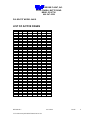
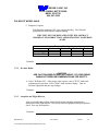
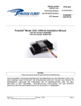
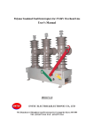
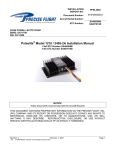
1
INSTALLATION REPORT NO. 08051 Serial Number PRECISE FLIGHT, INC. 63120 POWELL BUTTE ROAD BEND, OR 97701 800- 547-2558 PULSELITE STARLIGHT INSTALLATION MANUAL MODEL 2401S THIS DOCUMENT CONTAINS PROPRIETARY INFORMATION ON THE PRECISE FLIGHT, INC. COMPANY AND ITS RECEIPT OR POSSESSION DOES NOT CONVEY ANY RIGHTS TO REPRODUCE, DISCLOSE ITS CONTENTS, OR TO MANUFACTURE, USE, OR SELL ANYTHING IT MAY DESCRIBE. REPRODUCTION, DISCLOSURE, OR USE WITHOUT SPECIFIC WRITTEN AUTHORIZATION OF THE PRECISE FLIGHT, INC. COMPANY IS STRICTLY FORBIDDEN. REVISION C L:\FAA\Inventory\PULSELIT\2401S\8051C.doc 02/15/2001 PAGE i REVISION C L:\FAA\Inventory\PULSELIT\2401S\8051C.doc 02/15/2001 PAGE ii PRECISE FLIGHT, INC. 63120 POWELL BUTTE ROAD BEND, OR 97701 800- 547-2558 PULSELITE MODEL 2401S TABLE OF CONTENTS TABLE OF CONTENTS II LIST OF ACTIVE PAGES IV REVISIONS V 1. GENERAL INFORMATION 1-1 1.1. INTRODUCTION 1-1 1.2. PRODUCT DESCRIPTION 1-1 1.3. TECHNICAL CHARACTERISTICS 1-2 1.4. FACTORY SETTINGS 1-2 1.5. UNITS AND ACCESSORIES SUPPLIED 1-3 1.6. INSTALLATION APPROVAL BASIS 1-3 1.7. FIGURE - FAA FORM 337 1-4 1.8. ENVIRONMENTAL QUALIFICATIONS 1-5 1.9. FIGURE - ENVIROMENTAL TEST TABLE 1-5 1.10. 2. AIRCRAFT CERTIFICATION 1-6 INSTALLATION 2-1 2.1. GENERAL 2-1 2.2. UNPACKING AND INSPECTION 2-1 2.3. INITIAL BENCH CHECK 2-1 2.4. COOLING 2-2 2.5. MECHANICAL INSTALLATION 2.5.1. Mechanical installation - Pulselite Control Unit. REVISION C 02/15/2001 L:\FAA\Inventory\PULSELIT\2401S\8051C.doc 2-2 2-2 PAGE ii PRECISE FLIGHT, INC. 63120 POWELL BUTTE ROAD BEND, OR 97701 800- 547-2558 PULSELITE MODEL 2401S 2.5.2. 2.6. Mechanical installation - Switches 2-3 FIGURE - PHYSICAL DIMENSIONS 2-4 2.7. ELECTRICAL INSTALLATION 2.7.1. Electrical Installation 2-5 2-5 2.8. FIGURE - BLOCK DIAGRAM 2.8.1. Determine the amperage on individual channels. 2-6 2-7 2.9. 2-7 FIGURE - WIRE TABLE 2.10. FIGURE - PINOUT TABLE 2-8 2.11. FIGURE - CONNECTOR CONFIGURATION 2-9 3. TESTING 3.1. 3-1 INSTALLATION TESTING 3-1 3.2. EMI / RFI TESTING 3.2.1. Procedures 3.2.2. Communications 3.2.3. Ground Navigation Systems 3.2.4. Weather Radar 3.2.5. Autopilot and Flight Director 3.2.6. Conclusion 4. OPERATION 4.1. 5. 6. 3-2 3-3 3-3 3-4 3-6 3-6 3-7 4-1 NORMAL OPERATION 4-1 DOCUMENTATION 5-1 5.1. DOCUMENTATION 5-1 5.2. RETURN AUTHORIZATION 5-1 5.3. WARRANTY SERVICE 5-1 APPENDIX A 6.1.1. 6-1 PARTS LIST REVISION C L:\FAA\Inventory\PULSELIT\2401S\8051C.doc 6-1 02/15/2001 PAGE iii PRECISE FLIGHT, INC. 63120 POWELL BUTTE ROAD BEND, OR 97701 800- 547-2558 PULSELITE MODEL 2401S LIST OF ACTIVE PAGES ORIGINAL PAGE REV Title ii iii iv C v C 1-1 A 1-2 1-3 1-4 1-5 1-6 1-7 2-1 2-2 2-3 B 2-4 2-5 2-6 C 2-7 C 2-8 2-9 2-10 2-11 2-12 A 2-13 2-14 A 2-15 3-1 3-2 3-3 3-4 3-5 3-6 3-7 3-8 4-1 5-1 6-1 ADDED PAGES PAGE REV PAGE REV PAGE REVISION C L:\FAA\Inventory\PULSELIT\2401S\8051C.doc REV 02/15/2001 PAGE iv PRECISE FLIGHT, INC. 63120 POWELL BUTTE ROAD BEND, OR 97701 800- 547-2558 PULSELITE MODEL 2401S REVISIONS REV NO. A PAGE 1-1 2-12 2-14 DESCRIPTION Revise number of output channels Revise connector reference numbers Revise connector pinout DATE NAME 01/20/00 DJC 01/20/00 DJC 01/20/00 DJC B 2-3 2-6 Revise switch function Revise Figure 2.8: Block Diagram 11/27/00 11/27/00 DJC DJC C 2-6 2-7 Revise Pulselite CB specification in diagram Revise wording to reflect values of circuit breaker 02/15/01 02/15/01 MAO MAO 02/15/2001 PAGE REVISION C L:\FAA\Inventory\PULSELIT\2401S\8051C.doc v PRECISE FLIGHT, INC. 63120 POWELL BUTTE ROAD BEND, OR 97701 800- 547-2558 PULSELITE MODEL 2401S 1. GENERAL INFORMATION 1.1. INTRODUCTION This manual contains information regarding the physical, mechanical and electrical characteristics, as well as installation information pertaining to the Precise Flight Pulselite Model 2401S Control Unit. For maintenance and repair information, contact Precise Flight Inc. 1.2. PRODUCT DESCRIPTION The Pulselite Model 2401S Control Units are a compact set of electrical components that will apply regulated pulsing power to the landing, taxi, or recognition lights instead of the normal steady on. The Pulselite connects easily to an aircraft's external lighting system, and may be installed on a wide variety of aircraft with differing light sequence combinations. The control circuit of the Pulselite requires 24 / 28VDC. The four separate controlled power circuits of the 2401S Model are to pulse four DC Powered aircraft lamps (Up to 600 watts per Lamp). Pulsing the landing lights enhances the aircraft flight path recognition quality and may be utilized any time the pilot desires. By flashing the landing, taxi, and recognition lights approx. 46 times per minute in a variety of patterns, the Pulselite Control Unit creates an illusion of exaggerated motion that other pilots can immediately recognize and avoid. Precise Flight recommends that the landing lights be turned on steady (full time) when the aircraft is within 200' AGL at night. Due to possible disorientation the Pulselite should not be operated in clouds at night, or on the ground. The landing lights may be turned on steady rate, by simply switching the original landing/taxi/recognition lights on. REVISION C L:\FAA\Inventory\PULSELIT\2401S\8051C.doc 02/15/2001 PAGE 1-1 PRECISE FLIGHT, INC. 63120 POWELL BUTTE ROAD BEND, OR 97701 800- 547-2558 PULSELITE MODEL 2401S 1.3. TECHNICAL CHARACTERISTICS Weight: 1.95 pounds 0.88 kilograms Cooling: Radiation and Convection Dimensions: 5.45 in. W, 7.63 in. D, 2.18 in. H 13.84 cm W, 19.38 cm D, 5.54 cm H Operating Voltages 28 VDC Control Voltage (11 - 29 VDC) 28 VDC Switching Voltage - Model 2401S Operating Current 0.05 amps Maximum Load per Switching Circuit 600 Watt DC Number of circuits 4 Usage limitations Less than 200 ft AGL at Night & IMC Conditions Ambient operating range -50º F to +158º F -45º C to +70º C 1.4. FACTORY SETTINGS Pulse rate 43 - 48 Pulses per minute Sequence normal 2 lights On - 2 lights off Lamp brightness Full power during Pulse (Slight resistance through Pulselite Control Unit) REVISION C L:\FAA\Inventory\PULSELIT\2401S\8051C.doc 02/15/2001 PAGE 1-2 PRECISE FLIGHT, INC. 63120 POWELL BUTTE ROAD BEND, OR 97701 800- 547-2558 PULSELITE MODEL 2401S 1.5. UNITS AND ACCESSORIES SUPPLIED Pulselite Model 2401S Kit including: a) b) c) d) e) f) 1.6. Pulselite Control Unit Copy of the Supplemental Type Certificate Switches or Switch Specification Wire Harness or Wiring Harness Drawing Installation Wiring Diagrams Installation Drawing INSTALLATION APPROVAL BASIS The person who performs or supervises the installation of the Pulselite Model 2401S, may be required to prepare FAA form 337. See Fig. 1-7 for a Sample Description of Work Accomplished. Data that can be used as a basis for approval for return to service are: A. AC 43.13-1A; Acceptable Methods, Techniques and Practices, Aircraft Inspection and Repair. B. AC 43.13-2A; Acceptable Methods, Techniques and Practices, Aircraft Alterations C. FAA approved Manufacturer's Installation Instructions. Equipment installation procedures do not differ significantly among various aircraft. The installation and operation of the Pulselite Model 2401S does not materially affect the aircraft operation or performance. The Sample Description of Work Accomplished (Figure 1-7) is suggested language provided as a convenience to the installing agency. The information and wording should be modified to correctly describe the particular installation. Precise Flight Inc. can assume no responsibility for the alteration of the airframe or electrical system. REVISION C L:\FAA\Inventory\PULSELIT\2401S\8051C.doc 02/15/2001 PAGE 1-3 PRECISE FLIGHT, INC. 63120 POWELL BUTTE ROAD BEND, OR 97701 800- 547-2558 PULSELITE MODEL 2401S 8. Description of Work Accomplished (If more space is required, attach additional sheets. Identify with aircraft nationality and registration mark and date work completed.) A. The following components were installed: PULSELITE UNIT, MODEL 2401S, S/N SWITCH - (Switch P/N) B. The Unit was installed in (position in the aircraft) according to instructions in the PRECISE FLIGHT INSTALLATION MANUAL MODEL 2401S, P/N dated (insert current revision date of manual), and guidance in FAA Advisory Circulars 43.13-1A, chapter 11, and 43.13-2A, Chapter 1 & 2. C. An electrical load analysis was performed and the revised continuous load of the alternator (generator or other supply) does not exceed 80% of capacity. D. A complete operational test was performed according to PULSELITE 2401S Installation Manual P/N 8034 date ____ . The equipment performed satisfactorily and did not adversely affect existing components or systems in the aircraft, as required by FAR 23.1301, FAR 23.1431 (or FAR 25.1301, FAR 25.1431, FAR 27.1301, FAR 27.1431 , FAR 29.1301 or FAR 29.1431 as applicable). E. The aircraft equipment list was revised to reflect these changes; weight and balance data was revised and placed in the aircraft records. A Precise Flight Inc. PULSELITE Aircraft Flight Manual Supplement dated _____ was placed in the aircraft. 1.7. FIGURE - FAA FORM 337 REVISION C L:\FAA\Inventory\PULSELIT\2401S\8051C.doc 02/15/2001 PAGE 1-4 PRECISE FLIGHT, INC. 63120 POWELL BUTTE ROAD BEND, OR 97701 800- 547-2558 PULSELITE MODEL 2401S 1.8. ENVIRONMENTAL QUALIFICATIONS NOMENCLATURE MODEL NUMBER: MANUFACTURER SPECIFICATION: MANUFACTURER: PULSELITE 2401S PULSELITE PERFORMANCE REQUIREMENTS PRECISE FLIGHT INC. 63120 POWELL BUTTE RD. BEND, OR 97701 CONDITIONS DO160D SECTION DESCRIPTION OF TESTS CONDUCTED TEMPERATURE AND ALTITUDE TEMPERATURE VARIATION HUMIDITY OPERATIONAL SHOCK AND CRASH SAFETY VIBRATION EXPLOSION WATERPROOFNESS FLUIDS SUSCEPTIBILITY SAND AND DUST FUNGUS SALT SPRAY MAGNETIC EFFECT POWER INPUT VOLTAGE SPIKE CONDUCTED AUDIO FREQUENCY CONDUCTED SUSCEPTIBILITY INDUCED SIGNAL SUSCEPTIBILITY RADIO FREQUENCY SUSCEPTIBILITY RADIO FREQUENCY EMISSION 4.0 5.0 6.0 7.0 CATEGORY D2 NOT REQUIRED NOT REQUIRED NOT REQUIRED 8.0 9.0 10.0 11.0 12.0 13.0 14.0 15.0 16.0 17.0 18.0 CATEGORY C NOT REQUIRED CATEGORY W NOT REQUIRED NOT REQUIRED NOT REQUIRED NOT REQUIRED CLASS C CATEGORY Z CATEGORY A CATEGORY Z 19.0 CATEGORY Z 20.0 CATEGORY A 21.0 CATEGORY B 1.9. FIGURE - ENVIROMENTAL TEST TABLE REVISION C L:\FAA\Inventory\PULSELIT\2401S\8051C.doc 02/15/2001 PAGE 1-5 PRECISE FLIGHT, INC. 63120 POWELL BUTTE ROAD BEND, OR 97701 800- 547-2558 PULSELITE MODEL 2401S 1.10. AIRCRAFT CERTIFICATION Unless otherwise provided the Pulselite Model 2401S is approved by the following STC's. 1. Type of Certification: Supplemental Type Certificate 2. Certification Number: - NONE 3. Certification Basis: Approved Model Listing 4. Certification Date: NONE REVISION C L:\FAA\Inventory\PULSELIT\2401S\8051C.doc 02/15/2001 PAGE 1-6 PRECISE FLIGHT, INC. 63120 POWELL BUTTE ROAD BEND, OR 97701 800- 547-2558 PULSELITE MODEL 2401S 2. INSTALLATION 2.1. GENERAL The Pulselite Model 2401S should be installed according to this manual and AC 43.13-1A and -2A. Cable harnesses and mechanical supports must be fabricated by the installing agency to these requirements or supplied by Precise Flight for specific aircraft installations. This section contains interconnect diagrams, mounting dimensions, and other information pertaining to a Pulselite installation. 2.2. UNPACKING AND INSPECTION Exercise care when unpacking the equipment. Make a visual inspection of the unit for evidence of damage incurred during shipment. If a claim for damage is to be made, save the shipping container to substantiate the claim. The claim should be filed with the transportation company. Retain the container and packaging material after the equipment has been removed, should equipment storage or reshipment become necessary. 2.3. INITIAL BENCH CHECK Every Pulselite Model 2401S has been checked for operation before shipment. The installing agency can insure Pulselite operation before final installation by utilizing Paragraph 3.1 for this procedure. REVISION C L:\FAA\Inventory\PULSELIT\2401S\8051C.doc 02/15/2001 PAGE 2-1 PRECISE FLIGHT, INC. 63120 POWELL BUTTE ROAD BEND, OR 97701 800- 547-2558 PULSELITE MODEL 2401S 2.4. COOLING Elevated operating temperatures reduce reliability. Forced air-cooling is not required, however, allow approx. 1” of space around the control unit, for adequate convective cooling. Space is most critical on the unit sides so that the heat sink fins may dissipate heat at the proper rate. 2.5. MECHANICAL INSTALLATION Listed below are considerations to be examined before installing the Pulselite Model 2401S. Close attention to these suggestions will assure optimum performance when completed. 2.5.1. Mechanical installation - Pulselite Control Unit. A. Select a location for the Pulselite Control Unit, which is suitably ventilated for avionics. CAUTION: The standard Pulselite Model 2401S is not approved for use in a potentially explosive environment (refer to AC 43.13-2A, Chapter 2 Radio Installation). Locate Pulselite away from fire hazard zones, highly explosive or corrosive areas, potentially hazardous fluid areas; e.g. water, fuel, hydraulic fluid, or oxygen units, etc. B. The Pulselite Control Unit must be installed in a structurally substantiated location. A typical wiring diagram and physical installation is provided in Appendix A. C. Allow adequate space for installation of cables and connectors. D. The Pulselite Control Unit should be installed in an avionics bay or other suitable location. E. Although the Pulselite Control Unit can be installed in any axis, the preferred orientation is with the fins vertical. Use 4 10-32 pan head screws. Burnish one fastener location to insure proper ground. REVISION C L:\FAA\Inventory\PULSELIT\2401S\8051C.doc 02/15/2001 PAGE 2-2 PRECISE FLIGHT, INC. 63120 POWELL BUTTE ROAD BEND, OR 97701 800- 547-2558 PULSELITE MODEL 2401S 2.5.2. Mechanical installation - Switches A. The switch(s) should be located near the existing Aircraft Landing Light switches. REVISION C L:\FAA\Inventory\PULSELIT\2401S\8051C.doc 02/15/2001 PAGE 2-3 PRECISE FLIGHT, INC. 63120 POWELL BUTTE ROAD BEND, OR 97701 800- 547-2558 PULSELITE MODEL 2401S 2.6. FIGURE - PHYSICAL DIMENSIONS REVISION C L:\FAA\Inventory\PULSELIT\2401S\8051C.doc 02/15/2001 PAGE 2-4 PRECISE FLIGHT, INC. 63120 POWELL BUTTE ROAD BEND, OR 97701 800- 547-2558 PULSELITE MODEL 2401S 2.7. ELECTRICAL INSTALLATION All wiring should be secured to prevent chafing and faulty connections. Refer to Advisory Circular 43.13-2A. NOTE: Precise Flight recommends that Mil-W-22759 wiring be utilized in the Pulselite installation. DO NOT USE ALUMINUM WIRE NOTE: Wiring precautions. A. Observe proper cable routing, i.e. avoid tie-wrap joining power lines to antenna leads, intercom, or radio leads. B. Be sure that all connections are sound, i.e. avoid frayed or split conduit ends. C. Avoid sharp bends or undue strain on cables 2.7.1. Electrical Installation A. After the Pulselite Control Unit has been properly mounted determine the lighting pulse mode. Find the total wattage of the lamp(s) connected to the Pulselite Control Unit. Divide the highest total wattage by the voltage. The result will be the highest amperage rating on the Pulselite Control Unit. Amperages should not exceed 20 amps or 600 Watts DC. See Example below. REVISION C L:\FAA\Inventory\PULSELIT\2401S\8051C.doc 02/15/2001 PAGE 2-5 PRECISE FLIGHT, INC. 63120 POWELL BUTTE ROAD BEND, OR 97701 800- 547-2558 PULSELITE MODEL 2401S PULSELITE CONTROL UNIT MODEL 2401S AIRCRAFT EXTERNAL LIGHT 600 WATT MAX 28 VOLT DC AIRCRAFT EXTERNAL LIGHT 600 WATT MAX 28 VOLT DC 28 VDC AIRCRAFT EXTERNAL LIGHTS AIRCRAFT EXTERNAL LIGHT 600 WATT MAX 28 VOLT DC NOTE: DO NOT TIE INPUTS TOGETHER AIRCRAFT EXTERNAL LIGHT 600 WATT MAX 28 VOLT DC NOTE: JUNCTION BOX ATTACHMENTS SHOWN HERE FOR ILLUSTRATION ONLY MAINTAIN AIRCRAFT BUS SEPARATION ON AIRCRAFT PULSELITE INSTALLATION 2.8. FIGURE - BLOCK DIAGRAM REVISION C L:\FAA\Inventory\PULSELIT\2401S\8051C.doc 02/15/2001 PAGE 2-6 PRECISE FLIGHT, INC. 63120 POWELL BUTTE ROAD BEND, OR 97701 800- 547-2558 PULSELITE MODEL 2401S 2.8.1. Determine the amperage on individual channels. Proper wire and circuit protection should be observed. SEE Fig. 2-9 2.9. CU WIRE AN GAUGE CIRCUIT BREAKER FUSE 22 20 18 16 14 5 amps 7.5 10 15 20 5 amps 5 10 10 15 FIGURE - WIRE TABLE Approved wire specification is MIL-W- 22759/16 or equivalent. Fuse specification is MIL-F15160 or equivalent. Circuit breaker specification is MIL-C-5809 or equivalent. To protect the Pulselite control unit and insure proper installation, it is important to check that ground terminal, connector #1, pin "E", of the control unit is properly grounded to the aircraft frame with a No. 20 gauge wire or equivalent ground strap. Chassis of unit should be mounted to airframe and interfaces burnished to ensure a good ground. Power input for the Pulselite Control Unit is through Connector #1 Pin "F". A single 1 to 5 Amp circuit breaker is required between the aircraft bus and this pin. This pin provides internal control voltage for the Pulselite Control Unit. The Pulselite circuit breaker(s) should be located in the existing aircraft circuit breaker panel. However, if this is not possible, they may be located within the Pulselite switch panel. REVISION C L:\FAA\Inventory\PULSELIT\2401S\8051C.doc 02/15/2001 PAGE 2-7 PRECISE FLIGHT, INC. 63120 POWELL BUTTE ROAD BEND, OR 97701 800- 547-2558 PULSELITE MODEL 2401S PULSELITE CONNECTOR PINOUT TABLE CONNECTOR 1 - SHELL SIZE 20 MS3102 20-17 - P PIN VOLTAGE FUNCTION A 28V DC DC OUTPUT B 28V DC DC OUTPUT C 28V DC DC OUTPUT D 28V DC DC OUTPUT E F DC GND 28 VDC UNIT GROUND CONTROL POWER CONNECTOR 2 - SHELL SIZE 18 MS3102 18-10 - P CHNL A1 A2 C1 C2 PIN VOLTAGE FUNCTION A 28V DC DC INPUT B 28V DC DC INPUT C 28V DC DC INPUT D 28V DC DC INPUT MATING CONNECTOR MS 3106A-20 / 97-20-17-S CHNL A1 A2 C1 C2 MATING CONNECTOR MS 3106B-18 / 97-18-10-S 2.10. FIGURE - PINOUT TABLE REVISION C L:\FAA\Inventory\PULSELIT\2401S\8051C.doc 02/15/2001 PAGE 2-8 PRECISE FLIGHT, INC. 63120 POWELL BUTTE ROAD BEND, OR 97701 800- 547-2558 PULSELITE MODEL 2401S 2.11. FIGURE - CONNECTOR CONFIGURATION CONNECTOR 1 CONNECTOR 2 REVISION C L:\FAA\Inventory\PULSELIT\2401S\8051C.doc 02/15/2001 PAGE 2-9 PRECISE FLIGHT, INC. 63120 POWELL BUTTE ROAD BEND, OR 97701 800- 547-2558 PULSELITE MODEL 2401S 3. TESTING 3.1. INSTALLATION TESTING The following test procedure will evaluate the installation in the aircraft: 1. Check wiring & connections before applying power 2. Switch the Pulselite Unit to ON and verify that the appropriate Landing / Taxi / Recognition Lights are flashing on the aircraft. 3. Switch the appropriate Landing/ Taxi / Recognition Lights ON utilizing the existing switches and verify that the lights remain on without flashing. 4. Switch the Pulselite Control Unit off and the existing Landing/ Taxi / Recognition Light switches are off and verify that the Landing/ Taxi/ Recognition Lights are OFF. REVISION C L:\FAA\Inventory\PULSELIT\2401S\8051C.doc 02/15/2001 PAGE 3-1 PRECISE FLIGHT, INC. 63120 POWELL BUTTE ROAD BEND, OR 97701 800- 547-2558 PULSELITE MODEL 2401S 3.2. EMI / RFI TESTING The following is an outline for determining that no detrimental Electro Magnetic Interference (EMI) or Radio Frequency Interference (RFI) is caused by the installation of a Precise Flight Pulselite product per FAR 23.1431. 25.1431, 27.1431 or 29.1431. These procedures are not necessarily all encompassing in that they may not include all of the equipment installed in the airplane. If electronic and navigation equipment is installed which is not included in this document, consult the equipment manufacturer, an FAA approved repair station rated in the equipment involved ,or an FAA Avionics Inspector for applicable test procedures. The evaluation will be with a series of equipment checks, on the ground, to determine that no detrimental EMI/RFI effects are introduced into the aircraft by the Pulselite system. The electrical systems installed in the aircraft will be referred to as the Pulselite system in this procedure. The following tests should be performed by personnel familiar with aircraft systems and proper operation as well as the Pulselite equipment and its proper operation. Any and all discrepancies shall be noted. Any discrepancies noted during these procedures must be reported to Precise Flight, Inc. and evaluated for cause, extent and as to what corrective action should be taken to correct the problem. The aircraft may not be flown after discrepancies are found unless the Pulselite system is disconnected at the aircraft bus until such time as the problems have been corrected and the aircraft has successfully passed the ground portion of this test. Only then may the aircraft be flown to complete this test. REVISION C L:\FAA\Inventory\PULSELIT\2401S\8051C.doc 02/15/2001 PAGE 3-2 PRECISE FLIGHT, INC. 63120 POWELL BUTTE ROAD BEND, OR 97701 800- 547-2558 PULSELITE MODEL 2401S A record of this test shall be recorded in the aircraft logbook. The entry should include date, aircraft time, and results including any discrepancies note. The ground test results shall be recorded in the permanent aircraft records by the installing mechanic or a mechanic with the proper ratings. 3.2.1. Procedures During the following tests, the aircraft shall be supplied with adequate aircraft power at or above the minimum bus voltage for the aircraft. The airplane should be located for proper radio reception and radar operation, usually outside. 3.2.2. Communications A. Select Comm. 1 to a local frequency in the lower end of the COMM frequency band. Check for clarity of reception and background noise with all Pulselite equipment operating. Repeat for all Comm radios. Remarks: B. Select Comm. 1 to a local frequency in the upper end of the COMM frequency band. Check for clarity of reception and background noise with all Pulselite equipment operating. Repeat for all Comm radios. Remarks: REVISION C L:\FAA\Inventory\PULSELIT\2401S\8051C.doc 02/15/2001 PAGE 3-3 PRECISE FLIGHT, INC. 63120 POWELL BUTTE ROAD BEND, OR 97701 800- 547-2558 PULSELITE MODEL 2401S C. Verify that the intercom is free from noise and interference caused by the Pulselite installation. Remarks: 3.2.3. Ground Navigation Systems A. VOR/DME 1. Select VOR 1 receiver to a local frequency, center CDI needle of HSI with "TO" indication. Listen for background noise. 2. Switch Pulselite equipment on and off, check for interference and needle deviation. 3. Repeat for all other VHF NAV radios. 4. Tune VOR Nav 1 to a local VORTAC station with Pulselite equipment off. Note distance on DME and listen for noise. Turn Pulselite equipment on and compare distance readings and background noise. Repeat for all other VHF NAV radios. Remarks: B. Loran C 1. Observe Loran self test responses and signal to noise ratios. Turn Pulselite equipment on and recycle Loran and compare results. Remarks: REVISION C L:\FAA\Inventory\PULSELIT\2401S\8051C.doc 02/15/2001 PAGE 3-4 PRECISE FLIGHT, INC. 63120 POWELL BUTTE ROAD BEND, OR 97701 800- 547-2558 PULSELITE MODEL 2401S C. RNAV 1. VOR MODE - Set to VHF on a local frequency, center CDI and pilots HSI, turn on Pulselite equipment and check for interference. Remarks: 2. DME MODE - With Pulselite equipment off, set to local VHF frequency and note DME reading. Turn on Pulselite equipment and compare DME reading. Verify reading with known distance. Remarks: 3. RNAV MODE - With Pulselite equipment off, set local VHF frequency, set waypoint bearing to 180 and waypoint distance to 25 miles. Center CDI and note RNAV readings. Turn Pulselite equipment on and note any changes in RNAV readings. Remarks: REVISION C L:\FAA\Inventory\PULSELIT\2401S\8051C.doc 02/15/2001 PAGE 3-5 PRECISE FLIGHT, INC. 63120 POWELL BUTTE ROAD BEND, OR 97701 800- 547-2558 PULSELITE MODEL 2401S C. Magnetic Compass With Pulselite equipment OFF, note compass heading. Turn Pulselite equipment ON and compare compass heading. THIS TEST MUST BE REPEATED WITH THE AIRCRAFT HEADED IN FOUR DIRECTIONS APPROXIMATELY 90 DEGREES APART. Heading Pulselite ON Pulselite OFF Compass Readings Position 1 Position 2 Position 3 Position 4 Remarks: 3.2.4. Weather Radar CAUTION! USE CAUTION WHEN OPERATING RADAR! FOLLOW RADAR MANUFACTURERS RECOMMENDATIONS FOR SAFETY. A. Select "WxRadar ON". After proper warm up time, select "TEST" mode and confirm proper operation. Select "MAP" mode and note display. Turn on Pulselite equipment and note any changes. Remarks: 3.2.5. Autopilot and Flight Director Turn on autopilot and perform ground check per the autopilot manufacturers instructions in the flight manual. Turn on the Pulselite equipment and again perform check. Note any discrepancies. Remarks: REVISION C L:\FAA\Inventory\PULSELIT\2401S\8051C.doc 02/15/2001 PAGE 3-6 PRECISE FLIGHT, INC. 63120 POWELL BUTTE ROAD BEND, OR 97701 800- 547-2558 PULSELITE MODEL 2401S 3.2.6. Conclusion EMI Test Data Record Date: Make: Model: Ser. No: Witness: Location: Date: Comments: REVISION C L:\FAA\Inventory\PULSELIT\2401S\8051C.doc 02/15/2001 PAGE 3-7 PRECISE FLIGHT, INC. 63120 POWELL BUTTE ROAD BEND, OR 97701 800- 547-2558 PULSELITE MODEL 2401S 4. OPERATION 4.1. NORMAL OPERATION Pulsing the landing lights tend to enhance the aircraft flight path recognition quality and may be utilized any time the pilot desires. By flashing the landing, taxi, and recognition lights approx. 46 times per minute in a variety of patterns, Pulselite creates an illusion of exaggerated motion that other pilots can immediately recognize and avoid. While the Pulselite has been tested throughout the entire landing phase of flight, Precise Flight recommends that the landing lights be turned on steady (full time) when the aircraft is within 200' AGL at night. The Pulselite system should not be operated in clouds at night or in the close proximity of other aircraft on the ground, due to possible disorientation. The landing lights may be turned on steady at any time by simply switching the original landing/taxi/recognition lights on. The Pulselite will remain active until the Pulselite switch is turned OFF. REVISION C L:\FAA\Inventory\PULSELIT\2401S\8051C.doc 02/15/2001 PAGE 4-1 PRECISE FLIGHT, INC. 63120 POWELL BUTTE ROAD BEND, OR 97701 800- 547-2558 PULSELITE MODEL 2401S 5. DOCUMENTATION 5.1. DOCUMENTATION To ensure technical updates and notifications, fill out and return the warranty document and a copy of the 337, if appropriate. 5.2. RETURN AUTHORIZATION In order to expedite repair of units, call the factory for a return authorization number before returning equipment for service. 5.3. WARRANTY SERVICE Precise Flight warrants products in accordance with the warranty statement in effect at the time of equipment registration. All repairs are performed at the factory. Contact Precise Flight Inc. for a warranty / return authorization. All requests for warranty payment must be submitted on a standard warranty claim form, accompanied by the dealer invoice. Authorized warranty work performed by the dealer will be limited to removal and re-installation of units on an exchange basis. Precise Flight Inc. will bear the cost of warranty returns both ways via UPS surface delivery only. Precise Flight reserves the right to use reconditioned parts in repairing the product or to use reconditioned units as warranty replacements. For technical information and service, call 1-800-547-2558. REVISION C L:\FAA\Inventory\PULSELIT\2401S\8051C.doc 02/15/2001 PAGE 5-1 PRECISE FLIGHT, INC. 63120 POWELL BUTTE ROAD BEND, OR 97701 800- 547-2558 PULSELITE MODEL 2401S 6. APPENDIX A 6.1.1. PARTS LIST REVISION C L:\FAA\Inventory\PULSELIT\2401S\8051C.doc 02/15/2001 PAGE 6-1