1
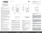
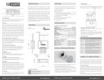
FIGURE 1
Dimensions (unit: mm)
APPLICATION
IN WALL SWITCH 2 RELAY; 1A AND 1C TYPE
MICROMODULE
MOTOR CONTROLLER
ANTENNA
L
N
INCLUDE_BUTTON
QUICK INSTALLATION GUIDE
v1.3
39.00
TRADEMARKS
Zipato and the Zipato logo are registered Trademarks. All
other product names mentioned herein may be trademarks or
registered trademarks of their respective companies.
Switch
N
NOTICE
M
NC1
NO1
S2
COM
SPECIFICATION
CAUTION
The connected devices and the flush-mounted receiver can
become damaged if devices are operated that do not correspond
to the technical specifications (see technical data).
DANGER
RISK OF FATAL INJURY FROM ELECTRIC CURRENT.
The device has no basic insulation and must therefore be installed
in a way that protects against accidental contact.
DANGER
RISK OF FATAL INJURY FROM ELECTRIC CURRENT.
When installing a wall plate, the distance between the cover’s
fixing brackets or screws and the connections of the flushmounted MicroModule Motor Controller must be at least 4
mm once installed. If the distance is less than 4 mm, a deeper
installation box must be used. The fixing brackets or screws of the
cover must not press against the housing. Only insulated tools may
be used for operation on the device, e.g. an insulated phase tester.
make your home smart
15.60
POWER
NO LOAD STANDBY POWER
TAKE CARE OF YOUR SAFETY
RISK OF ELECTROCUTION
All work on the device should only be carried out by trained and
skilled electricians. Observe the country-specific regulations.
N
Relay 1C type
ELECTROMAGNETIC COMPATIBILITY
DANGER
S2 S1 L
Motor
Relay 1A type
In proper state and when operated properly, the product complies
with all the requirements in respect of interference radiation
according to EN 301 489-17, EN 301 489-1 and EN 300 328. The
connections conducting HF signals must neither be manipulated
nor damaged.
Display extreme caution when using ladders or steps, please
follow manufacturer’s instructions. Be careful when using hand
and power tools and follow the manufacturer’s guidelines when
using them. Take care that the correct tools are used. Wear
goggles or protective clothing where required.
NO1
NEUTRAL
LIVE
S1
NC1
Although Zipato has attempted to ensure the accuracy of the
content of this manual, it is possible that this document may
contain technical inaccuracies, typographical, or other errors.
Zipato assumes no liability for any error in this publication, and for
damages, whether direct, indirect, incidental, and consequential
or otherwise, that may result from such error, including, but not
limited to loss of data or profits. Zipato provides this publication
“as is” without warranty of any kind, either express or implied,
including, but not limited to implied warranties of merchantability
or fitness for a particular purpose. The published information in
the manual is subject to change without notice. Zipato reserves
the right to make changes in the product design, layout, and driver
revisions without notification to its users. This version of the
Installation guide supersedes all previous versions.
0.48W (230V) 0.35W (120V)
47.50
INPUT VOLTAGE
110 ~230VAC
INTRODUCTION
FEATURES
The in-wall MicroModule Motor Controller is designed to switch
rise/lower roller shutter connected to its terminals using radio
waves, controllers and a push button directly connected to this
Roller Controller.
This in-wall MicroModule Motor Controller is a transceiver which
is a Z-WaveTM enabled device and is fully compatible with any
Z-WaveTM enabled network. Slim design let the Controller can
easily hide itself into the wall box and that will be good for the house
decoration.
The new smart relay calibration technology can reduce the inrush
current caused by the load and let the module work perfectly with
many kind of Roller Shutter.
This in-wall MicroModule Motor Controller is able to detect position
of the Shutter by using the patterned power measuring method, so
it can be remote controlled not only fully up or down, but also can be
adjusted to ex. 30% or 50%.
And when manual controlled by push button, the controller also
can memorize the position and send the new shutter position to its
controller (ex. IP-Gateway).
www.zipato.com
dopt newest Z-wave 400series chip, support multichannel
A
operation and higher data rate (9.6/40/100kbps)
Adopt Z-Wave protocol to secure the success of wireless two way
communication
Higher RF output power (+2.5dBm output power as compared to
-2.5dBm 300 series Z-wave module) to enhance the
communication range
With zero crossing technology to extend the number of switching
Slim design, easy install
Max load up to 1100W
After calibration, the controller can feedback the roller shutter
position
Overload protection
Z-Wave V6.02
Very low Electricity consumption, meet Europe year 2012 energyrelated products requirement directive 2009/125/EC no.
1275/2008
Z-Wave Certificated NoZC08-13070030
ZC08-13080002
LVD:EN 60669-2-1:2004+A1:2009+A12:2010,
EN 60669-2-2 :2006
EN 60669-1:1999+A1:2002+A2:2008+IS1:2009
R&TTE: EN 301489, EN 300200,
make your home smart
RF
REGULATION
FCC part15.249 / EN300 220-1/
DISTANCE
min. 40m indoor min. 100m outdoor
MECHANICAL
WEIGHT
DIMENSION (W x H x D)
30g
47.5x39x15.6 mm
ENVIRONMENT
OPERATION TEMPERATURE
HUMIDITY
0~40°C
85%RH max
LOAD
RESISTIVE LOAD
OVERLOAD
1100W (230V) 600W (120V)
1200W (230V) 700W(120V)
www.zipato.com 01
using Z-Wave command class, user can set a threshold watt to
get the warning caused by abnormal operation.
MM Motor Controller have overload protection function, and can
help to prevent short circuit caused by load.
There are 1 group (Group 1) for
the MM Motor Controller
Including a node ID allocated by Z-Wave Controller means
inclusion. Excluding a node ID allocated by Z-Wave Controller
means exclusion.
Failed or success in including/excluding the node ID can be
viewed from the Z-Wave Controller.
MICROMODULE
MOTOR CONTROLLER
QUICK INSTALLATION GUIDE
v1.3
ADDING TO Z-WAVE NETWORK
In the front casing, there is an include button with LED indicator
below which is used to carry out inclusion, exclusion, reset or
association. When first power is applied, its LED flashes on and
off alternately and repeatedly at 2-second intervals. It implies that
it has not been assigned a node ID and cannot work with Z-Wave
enabled devices.
LED INDICATION
Function
Description
LED Indication
No node ID
The Z-Wave Controller does
not allocate a node ID to the
MM Motor Controller.
2-second on,
2-second off
Have Z-Wave Controller
entered inclusion mode.
Inclusion
Pressing Include button three
times within 1.5 seconds will
enter inclusion mode.
Have Z-Wave Controller
entered exclusion mode.
Exclusion
Pressing Include button three
times within 1.5 seconds will
enter exclusion mode.
Node ID has been excluded.
Pressing Include button three
times within 1.5 seconds will
enter inclusion mode.
Reset
Within 1 second, press Include
button again for 5 seconds
until LED is off.
IDs are excluded.
Association
Have Z-Wave Controller
entered association mode.
OR
Pressing Include button three
times within 1.5 seconds will
enter association mode
One press one
flash
One press one
flash
2-second on,
2-second off
One press one
flash
2-second on,
2-second off
One press one
flash
make your home smart
PROGRAMMING
LED Indication
Motor
activate
No matter up or down, close or open, Led will
flash every second while Motor activate. When
S1 or S2 close to L, the LED will flash even when
the motor stop by itself, this is to let user know
the S1 or S2 still close and not been release yet.
No node ID
Under normal operation, when the MM Motor
Controller has not been allocated a node ID, the
LED flashes on and off alternately at 2-second
intervals. By pressing S1 S2 or Include button,
it will stop flashing temporarily. However, after
disconnect and reconnect the power of MM
Motor Controller, the LED will flash on and off
alternately at 2-second intervals.
Overload
When overload state occurs, the MM Motor
Controller is disabled and LED flashes on and
off alternately at 0.5 second intervals. MM Motor
Controller will send
alarm_type=8 alarm_Level=0xFF to Group1,
Overload state can be cleared by disconnect
and reconnect the MM Motor Controller to the
main power.
The MM Motor Controller will respond to BASIC and BINARY
commands that are part of the Z-Wave system.
BASIC_GET
When MM Motor Controller receive Basic Get
Command it will send Basic Report Command to report the
position of the shutter. When the report value is 0x00, that mean
the shutter is at the Bottom, if the report value is 0x63 or 0xFF
that mean the shutter is at the Top, any other value between
0x01~0x62 imply Shutter at the position between top and bottom.
Basic Get Command: [Command Class Basic, Basic Get]
[Command Class Multilevel Switch, Multilevel Switch Set,
Value = 0x00(0)] control the shutter to the bottom(0x00)
CHOOSING A SUITABLE LOCATION
INSTALLATION AND OPERATION
ut the in wall MM Motor Controller into a wall box and connect
P
the AC power wire L,N to MM Motor Controller connector L, N.
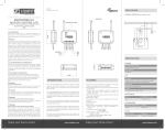
Connect the wall switch to the MM Motor Controller as shown in
picture above.
It is important to carry out a shutter calibration process before
you control the shutter to move. Press inclusion button over 3
seconds and release before the 6th second, the roller shutter
controller will start the shutter calibration process. The process
is composed of three continue stages. The shutter move to the
TOP in first stage, and move to the BOTTOM in second stage, and
move to the TOP again in third stage. Then MM Motor Controller
will know the total range of UP and DOWN.
During the shutter calibration process, any emergencies happen
you can press and release the include button to stop the process.
If user found the direction is reverse, this may cause by the wrong
connection of NC and NO to the motor, please change NC and NO
connection and execute calibration process again.
For safe issue, please select the motor which can stop by itself
when go to bottom end or top end.
To manually switch up and down of the shutter, simply press the
external switch S1 or S2. The detail is described in Z-Wave
configuration section (External switch type) of this manual.
MM Motor Controller built in meter function and can read the
Watt, KWh, V(Voltage), I(Current), PF(Power Factor) of the load by
www.zipato.com
Multilevel Switch Report Command:
[Command Class Multilevel Switch, Multilevel Switch Report,
Value = 0x00(BOTTOM)]
[Command Class Multilevel Switch, Multilevel Switch Report,
Value = 0x01~0x62(Between BOTTOM and TOP)]
[Command Class Multilevel Switch, Multilevel Switch Report,
Value = 0x63/0xFF(TOP)]
ULTILEVEL SWITCH START LEVEL CHANGE
M
This is the command which user can move the shutter up to the
top or down to the bottom.
[Command Class Multilevel Switch, Multilevel Switch Start
Level Change, Up/Down Value]
[Command Class Basic, Basic Set, Value = 0x00(0)] control the
shutter to the bottom(0x00)
[Command Class Basic, Basic Set, Value = 0x01-0x62] control
the shutter to the position between bottom and top
ULTILEVEL SWITCH GET
M
When MM Motor Controller receive Multilevel Switch
Get Command, it will send Multilevel Switch Report Command
to report the position of the shutter. When the report value is
0x00, that mean the shutter is at the Bottom, if the report value
is 0x63 or 0xFF that mean the shutter is at the top, any other
value between 0x01~0x62 imply shutter at the position between
top and bottom.
Switch Multilevel Get Command:
[Command Class Multilevel Switch, Multilevel Switch Get]
BASIC_SET
MM Motor Controller can accept Basic Set Command
which value is either (0x00)Bottom or Top (0x63/0xFF) or (0x010x62) the position between TOP and Bottom. Other value (0x640xFE) is not acceptable.
[Command Class Basic, Basic Set, Value = 0x63 or 0xFF]
control the shutter to the top (0xFF)
o not locate the MM Motor Controller facing direct sunlight,
D
humid or dusty place.
The suitable ambient temperature for the MM Motor Controller is
0°C~40°C.
Do not locate the MM Motor Controller where exists combustible
substances or any source of heat, e.g. fires, radiators, boiler etc.
After putting it into use, the body of MM Motor Controller will
become a little bit hot of which phenomenon is normal.
[Command Class Multilevel Switch, Multilevel Switch Set,
Value = 0x01-0x62] control the shutter to the position between
Bottom and Top.
Basic Report Command:
[Command Class Basic, Basic Report, Value = 0x00 (BOTTOM)]
[Command Class Basic, Basic Report, Value = 0x01~0x62
(Between BOTTOM and TOP)]
[Command Class Basic, Basic Report, Value = 0x63/0xFF
(TOP)]
Command which value is either (0x00) Bottom or Top (0x63 or
0xFF) or (0x01-0x62) the position between TOP and Bottom.
Other value (0x64-0xFE) is not acceptable.
[Command Class Multilevel Switch, Multilevel Switch Set,
Value = 0x63 or 0xFF(255)] control the shutter to the top (0xFF)
BASIC COMMAND CLASS
State Type
AUTO INCLUSION
The function of auto inclusion will be executed as long as the MM
Motor Controller does not have Node ID and just connect the MM
Motor Controller to main power.
Note: Auto inclusion timeout is 4 minute during which the node
information of explorer frame will be emitted once every 5
seconds. Unlike “inclusion” function as shown in the table below,
the execution of auto inclusion is free from pressing the Include
button on the MM Motor Controller.
The table below lists an operation summary of basic Z-Wave
functions. Please refer to the instructions for your Z-Wave
Certificated Primary Controller to access the Setup function, and
to include/exclude/associate devices.
Up/Down Bit:
If Up/Down Bit=0x00 Shutter move up
If Up/Down Bit=0x01 Shutter move down
If Up/Down Bit=0x03 no move
BINARY SWITCH COMMAND CLASS
BINARY_SWITCH_GET
When MM Motor Controller receive Binary Switch Get
Command, it will send Binary Switch Report Command to report
the position of the shutter. When the report value is 0x00, that
mean the Shutter is bottom down, if the report value is 0xFF that
mean the Shutter is at the top. But if report value is 0xFE means
the position is unknown.
Binary Switch Get Command:
[Command Class Binary Switch, Binary Switch Get]
Binary Switch Report Command:
[Command Class Binary Switch, Binary Switch Report, Value
= 0x00(BOTTOM)]
[Command Class Binary Switch, Binary Switch Report, Value =
0xFE(UNKNOWN)]
[Command Class Binary Switch, Binary Switch Report, Value
= 0xFF(TOP)]
[Command Class Multilevel Switch, Multilevel Switch Start
Level Change, Up/Down=0x01] control the shutter to the
bottom (0x00)
[Command Class Multilevel Switch, Multilevel Switch Start
Level Change, Up/Down=0x03] Don’t move the shutter or stop
the moving shutter
Ignore_Start_Level,Start_Level, Dimming_Duration, Inc/
Dec, Step_size can not be used.
M Motor Controller can not control the speed of motor.
M
It may have some distance error caused by motor start up
time.
If user found the error become significant, you may using S1
or S2 move shutter to the end or remote move shutter to
0% and 100%, and that will automatically calibrate this
error.
Multilevel switch stop level change
When receive Multilevel Switch Stop Level change Command
MM Motor Controller will stop the motor.
ATT.
BINARY_SWITCH_SET
MM Motor Controller can only accept Binary Switch
Set Command which value is either (0x00) Bottom or Top (0xFF),
other value is not acceptable.
[Command Class Binary Switch, Binary Switch Set, Value =
0xFF(255)]
control the shutter to the top (0xFF). But if the shutter is on
the way down,
this command will stop the shutter.
[Command Class Binary Switch, Binary Switch Set, Value =
0x00(0)]
control the shutter to the bottom(0x00). But if the shutter is
on the way up,
this command will stop the shutter.
MULTILEVEL SWITCH COMMAND CLASS (VERSION 3)
[Command Class Multilevel Switch, Multilevel Switch Start
Level Change, Up/Down=0x00] control the shutter to the top
(0xFF)
ULTILEVEL SWITCH SET
M
MM Motor Controller can accept Multilevel Switch Set
make your home smart
SCENE ACTIVATION COMMAND CLASS
cene Activation Set Command
S
When MM Motor Controller receive Scene Activation
Set command, it will read the level of the pre-configured Scene
ID from EEPROM. And it will be controlled as a Multilevel Switch
Set command. The Dimming Duration of the command will be
ignored because MM Motor Controller can not control
the speed of motor.
www.zipato.com 02
MICROMODULE
MOTOR CONTROLLER
Precision = 1
Scale = 0x02(W)
Size = 4 Bytes (Meter Value)
Meter Value 1 = (W) MSB
Meter Value 2 = (W)
Meter Value 3 = (W)
Meter Value 4 = (W)LSB
QUICK INSTALLATION GUIDE
v1.3
Rate Type = 0x01
Meter Type = 0x01
Precision = 2
Scale = 0x00 (KWh)
Size = 4 bytes (Meter Value)
Meter Value 1 = (KWh) MSB
Meter Value 2 = (KWh)
Meter Value 3 = (KWh)
Meter Value 4 = (KWh) LSB
[Command Class Scene Actuator Configuration, Scene
Actuator Configuration Set, Scene ID=1~255, Override bit=1,
Level=0~99 or 255] The Level value in this Command is
associated to the Scene ID.
Scene Actuator Configuration Set Command
[Command Class Scene Actuator Configuration, Scene
Actuator Configuration Get, Scene ID=1~255 ]
Example:
Scale = 0x00 (KWh)
Precision = 2
Size = 4 Bytes (KW/h)
Meter Value 1 = 0x00(KWh)
Meter Value 2 = 0x01(KWh)
Meter Value 3 = 0x38(KWh)
Meter Value 4 = 0xA3(KWh).
Accumulated power consumption (KW/h) = (Meter Value
2*65536) + (Meter Value 3*256) + (Meter Value 4) = 800.35
(KW/h)
AC load Voltage (V) When receiving Meter Get Command, it
will report Meter Report Command to the node asked.
Meter Get Command: [Command Class Meter, Meter Get,
Scale =0x04(V)]
There is only one group called Group1, there is only one node for
Group1 which support MULTILEVEL_SWITCH_REPORT, METER_
REPORT_COMMAND_V3, ALARM_REPORT
eport the shutter position
R
Every time when user press S1 or S2 and let shutter to move,
MM Motor Controller will report the position status
to controller, and at the moving process when change over 10%
MM Motor Controller will send Multilevel Switch
Report to Group 1 also.
Multilevel Switch Report: Ex. Report position at 30%
[Command Class Multilevel Switch, Multilevel Switch
Report, Value = 30(%)]
Meter Command Class
The Switch will report its (1) instant Power Consumption
(Watt) or (2) accumulated power consumption(KWH) or (3) AC
load Voltage (V) or (4) AC load current ( I ) (5) load power factor
(PF) to Z-Wave Controller after receive the Meter Get Command
from Z-Wave Controller. When the power consumption of load
vary over 5%, it will send Meter report to the nodes of Group as
well.
Instant Power Consumption (Watt) of Switch When receiving
Meter Get Command, it will report Meter Report Command
to the node asked.
Meter Report Command:
[Command Class Meter, Meter Report, scale(bit 2) +Rate Type
+Meter Type, Precision + Scale(bit 1,0)+ Size, Meter Value 1,
Meter Value 2]
Rate Type = 0x01
Meter Type = 0x01
Precision = 1
Scale = 0x04(V)
Size = 2 Bytes (Meter Value)
Meter Value 1 = High Byte (V)
Meter Value 2 = Low Byte (V)
Example:
Scale = 0x04 (V)
Precision = 1
Size = 2 (2 Bytes of V)
Meter Value 1 = 0x09(V)
Meter Value 2 = 0x01(V)
AC load Voltage = (Meter Value
1*256) +(Meter Value 2)= 230.5 (V)
C load current ( I ) When receiving Meter Get Command, it
A
will report Meter Report Command to the node asked.
Meter Get Command: [Command Class Meter, Meter Get,
Scale =0x05(I)]
Meter Report Command:
[Command Class Meter, Meter Report, scale(bit 2) +Rate Type
+Meter Type, Precision + Scale(bit 1,0)+ Size, Meter Value 1,
Meter Value 2]
Meter Get Command: [Command Class Meter, Meter Get,
Scale =0x02(W)]
Meter Report Command: [Command Class Meter, Meter
Report, scale(bit 2)
+Rate Type +Meter Type, Precision + Scale(bit 1,0)+ Size, Meter
Value 1, Meter Value 2, Meter Value 3, Meter Value 4]
Rate Type = 0x01
Meter Type = 0x01
Example:
Meter Value 1 = 0x00 (W)
make your home smart
Meter Get Command: [Command Class Meter, Meter Get, Scale
=0x06(PF)]
Meter Report Command:
[Command Class Meter, Meter Report, scale(bit 2) +Rate Type
+Meter Type, Precision + Scale(bit 1,0)+ Size, Meter Value 1]
Accumulated Power Consumption (KW/h)
When receiving Meter Get Command, it will report Meter
Report Command to the node asked.
Meter Report Command: [Command Class Meter,Meter
Report, scale(bit 2) +Rate Type +Meter Type, Precision +
Scale(bit 1,0)+ Size, Meter Value 1, Meter Value 2, Meter Value
3, Meter Value 4]
SCENE ACTUATOR CONFIGURATION COMMAND CLASS
Z-WAVE’S GROUPS INTRODUCTION (ASSOCIATION
COMMAND CLASS VERSION 1 )
Load power factor (PF) When receiving Meter Get Command,
it will report Meter Report Command to the node asked.
Rate Type = 0x01
Meter Type = 0x01
Precision = 2
Scale = 0x06(PF)
Size = 1 Bytes
Meter Value 1
Meter Get Command: [Command Class Meter, Meter Get,
Scale = 0x00
[Command Class Scene Actuator Configuration, Scene
Actuator Configuration Set, Scene ID=1~255, Override bit=0,
Level=0~99 or 255] The current setting of MM Motor Controller
will not be override.
[Command Class Scene Actuator Configuration, Scene
Actuator Configuration Report, Scene ID=1~255, Level=0~99
or 255, Dimming Duration=0~0xFE] Report the Pre-configured
Scene ID of MM Motor Controller.
Meter Value 2 = 0x00 (W)
Meter Value 3 = 0x03 (W)
Meter Value 4 = 0xEA (W)
Meter(W) = Meter Value 3 *256
+ Meter Value 4 = 100.2W
Rate Type = 0x01
Meter Type = 0x01
Precision = 2
Scale = 0x05(I)
Size = 2 Bytes (Meter Value)
Meter Value 1 = High Byte (I)
Meter Value 2 = Low Byte (I)
Example:
Scale = 0x05 (I)
Precision = 2
Size = 2 (2 Bytes of I)
Meter Value 1 = 0x01(I)
Meter Value 2 = 0x21(I)
AC load current = (Meter Value
1*256) +(Meter Value 2)= 2.89 (A)
www.zipato.com
Example:
Scale = 0x06 (PF)
Precision = 2
Size = 1 (1 Byte of PF)
Meter Value 1 = 0x63(PF)
Load power factor (PF) = Meter Value 1 = 0.99
Z-WAVE’S CONFIGURATION
eset Accumulated Power Consumption (KWh) This
R
command is to reset the Accumulated Power Consumption
(KWh) to 0 Meter Reset Command.
[Command Class Meter, Meter Reset]
larm Report Command
A
When MM Motor Controller detect Overload, it
will send Alarm_Report to Group1, Alarm Type = 0x08,
Alarm Level=0xFF. When receive Alarm_Get command and the
MM Motor Controller not in overload status , it will
send Alarm_Report, Alarm Type = 0x08, Alarm Level=0x00.
Alarm Report
When in Two Push Button switch type, S1 or S2 close to
L and not been release, and MM Motor Controller
receive some control moving command from Z-Wave RF
(Ex. BASIC_SET, BINARY_SWITCH_SET, MULTILEVEL_
SWITCH_SET, MULTILEVEL_SWITCH_START_LEVEL_
CHANGE or MULTILEVEL_SWITCH_STOP_LEVEL_CHANGE),
MM Motor Controller won’t do any movement
change but report alarm to Group1 this indicate that the S1
or S2 not been released.
When MM Motor Controller detect a overload
power, it will report alarm to Group1.
[Command_Class_Alarm, Alarm_Report, Alarm Type = 0x08,
Alarm Level = 0xFF (Overload)]
[Command_Class_Alarm, Alarm_Report, Alarm Type = 0x08,
Alarm Level = 0x00 (Normal)]
COMMAND CLASSES
COMMAND_CLASS_SWITCH_BINARY
COMMAND_CLASS_BASIC
COMMAND_CLASS_MANUFACTURER_SPECIFIC_V2
COMMAND_CLASS_VERSION
COMMAND_CLASS_ASSOCIATION
COMMAND_CLASS_METER_V3
COMMAND_CLASS_CONFIGURATION
COMMAND_CLASS_SWITCH_MULTILEVEL_V3
COMMAND_CLASS_ALARM
COMMAND_CLASS_SCENE_ACTIVATION
COMMAND_CLASS_SCENE_ACTUATOR_CONF
When in Two Push Button switch type, S1 or S2 are closed
and not released to open, and MM Motor Controller
receive any control moving command from Z-Wave RF, it will
report alarm to Group1.
att Meter Report Period
W
If the setting is configured for 1hour (set value =720), the
MM Motor Controller will report its instant power
consumption every 1 hour to the node of correspond Group. The
maximum interval to report its instant power consumption is 45
hours (5s*32767/3600=45hr). Default value is 1 hour.
WH Meter Report Period
K
If the setting is configured for 1hour (set value =6), the
MM Motor Controller will report its Accumulated
Power Consumption (KW/h) every 1 hour to the node
of correspond Group. The maximum interval to report
its Accumulated Power Consumption (KW/h) is 227.55 days
(10min*32767/1440=227.55 days). Default value=1 hour.
hreshold of Watt for Load Caution
T
This is a warning when the wattage of load over the preset
threshold value, If the setting value is 1100, when the load
wattage over this value, MM Motor Controller will send
Watt Meter Report command to the node of correspond Group.
Default value=1100W.
hreshold of KWh for Load Caution
T
This is a warning when the KWh of load over the preset threshold
value, If the setting value is 10000, when the Accumulated Power
Consumption of Relay1 or Relay2 over this value, MM
Motor Controller will send KWh Meter Report command to the
node of correspond Group, minimum value is 1KWh and default
value is 10000 kWh.
evel Report mode
L
Mode 1: In 5 seconds period after controlled by a moving
command, it will report the destination level when received
request command. Out of the 5 seconds period, it will report the
actual level of the shutter when received
Mode 2: Whenever the shutter move pass a 10 percent level, it
will auto report the level to Group 1 node.
[Command_Class_Alarm, Alarm_Report, Alarm Type = 0x01,
Alarm Level = 0xFF (S1 or S2 close to L)]
[Command_Class_Alarm, Alarm_Report, Alarm Type = 0x08,
Alarm Level = 0x00 (Normal)]
Configuration
Parameter
Function
Size
(Bytes)
Value
Unit
Default
Description
1
Watt Meter Report Period
2
0x01-0x7FFF
5s
720
5*720s=3600s=1 hour
2
KWH Meter Report Period
2
0x01-0x7FFF
10min
6
6*10min= 1 hour
1100
3
Threshold of Watt for Load Caution
2
10-1100
1watt
4
Threshold of KWH for Load Caution
2
1-10000
1KWh
5
External switch type
1
1-2
6
Level report mode
1
make your home smart
1-2
10000
1
1: One Push button
2:Two Push button
1
1:Report destination level in 5s
2:Report 10 percent level while running
www.zipato.com 03
MICROMODULE
MOTOR CONTROLLER
QUICK INSTALLATION GUIDE
v1.3
TECHNICAL SUPPORT
Having trouble installing your new product?
Zipato’s website contains the latest user documentation and
software updates for Zipato products and services.
www.zipato.com
CONTACT SUPPORT
E-MAIL: [email protected]
(Mon-Fri) 9.00am-05.00pm (CET)
MODELS AND FREQUENCIES
MODELS
EUROPEAN UNION - EU version
UNITED STATES - US version
RUSSIA - RU version
ISRAEL - IS version
AUSTRALIA - AU version
INDIA - IN version
FREQUENCIES
EUROPEAN UNION - EU
UNITED STATES - US
RUSSIA - RU
ISRAEL - IS
AUSTRALIA - AU
INDIA - IN
ph-pan08.eu
ph-pan08.us
ph-pan08.ru
ph-pan08.is
ph-pan08.au
ph-pan08.in
868.42 MHz
908.42MHz
869.02MHz
916.02MHz
921.42MHz
865.20MHz
LIMITED PRODUCT WARRANTY
GENERAL TERMS
Nothing in this Limited Product Warranty affects your statutory
rights as a consumer.
The Limited Product Warranty set forth below is given by Tri plus
grupa d.o.o. (Europe) (herein referred to as “ZIPATO”). This Limited
Product Warranty is only effective upon presentation of the proof
of purchase. Upon further request by ZIPATO, this warranty card
has to be presented, too.
EXCEPT AS EXPRESSLY SET FORTH IN THIS LIMITED WARRANTY,
ZIPATO MAKES NO OTHER WARRANTIES, EXPRESS OR IMPLIED,
INCLUDING ANY IMPLIED WARRANTIES OF MERCHANTABILITY
AND FITNESS FOR A PARTICULAR PURPOSE. ZIPATO EXPRESSLY
DISCLAIMS ALL WARRANTIES NOT STATED IN THIS LIMITED
WARRANTY. ANY IMPLIED WARRANTIES THAT MAY BE IMPOSED
BY LAW ARE LIMITED IN DURATION TO THE LIMITED WARRANTY
PERIOD. TO THE EXTENT ALLOWED BY LOCAL LAW, THE
REMEDIES IN THIS WARRANTY STATEMENT ARE CUSTOMER’S
SOLE AND EXCLUSIVE REMEDIES AGAINST ZIPATO. THEY DO
NOT, HOWEVER, AFFECT OR RESTRICT THE RIGHTS YOU HAVE
AGAINST THE BUSINESS YOU BOUGHT A ZIPATO PRODUCT FROM.
IN NO EVENT WILL ZIPATO BE LIABLE FOR LOSS OF DATA OR FOR
make your home smart
INDIRECT, SPECIAL, INCIDENTAL, CONSEQUENTIAL (INCLUDING
LOST PROFIT OR DATA), OR OTHER DAMAGE, WHETHER BASED IN
CONTRACT, TORT, OR OTHERWISE. HOWEVER, NOTHING IN THIS
AGREEMENT LIMITS ZIPATO’S LIABILITY TO YOU (I) IN THE EVENT
OF DEATH OR PERSONAL INJURY TO THE EXTENT RESULTING
FROM ZIPATO’S NEGLIGENCE, OR (II) TO THE EXTENT RESULTING
FROM ANY FRAUDULENT MISREPRESENTATION ON THE PART
OF ZIPATO, OR (III) TO THE EXTENT ARISING UNDER PART 1
OF THE CONSUMER PROTECTION ACT 1987 OF THE UNITED
KINGDOM. SOME STATES OR COUNTRIES DO NOT ALLOW: (1) A
DISCLAIMER OF IMPLIED WARRANTIES; (2) A LIMITATION ON HOW
LONG AN IMPLIED WARRANTY LASTS OR THE EXCLUSION; OR
(3) LIMITATION OF INCIDENTAL OR CONSEQUENTIAL DAMAGES
FOR CONSUMER PRODUCTS. IN SUCH STATES OR COUNTRIES,
SOME EXCLUSIONS OR LIMITATIONS OF THIS LIMITED WARRANTY
MAY NOT APPLY TO YOU. THIS LIMITED WARRANTY GIVES YOU
SPECIFIC LEGAL RIGHTS. YOU MAY ALSO HAVE OTHER RIGHTS
THAT MAY VARY FROM STATE TO STATE OR FROM COUNTRY TO
COUNTRY. YOU ARE ADVISED TO CONSULT APPLICABLE STATE OR
COUNTRY LAWS FOR A FULL DETERMINATION OF YOUR RIGHTS.
This Limited Product Warranty applies to ZIPATO branded hardware
products (collectively referred to as “ZIPATO Hardware Products”)
sold by ZIPATO (Europe), its European subsidiaries, affiliates,
authorized resellers, or country distributors (collectively referred to
as “ZIPATO Resellers”) with this Limited Product Warranty.
showing the date of purchase of the product, is your proof of the
purchase date. You may be required to provide proof of purchase
as a condition of receiving warranty service. You are entitled to
warranty service according to the terms and conditions of this
document if a repair to your ZIPATO branded hardware is required
within the Limited Product Warranty Period.
The term “ZIPATO Hardware Product” is limited to the hardware
components and all its internal components including firmware.
The term “ZIPATO Hardware Product” DOES NOT include any
software applications or programs.
If a product defect occurs, ZIPATO’s sole obligation shall be to
repair or replace any defective Zipato Hardware Product free of
charge provided it is returned to an Authorized ZIPATO Service
Centre during the Limited Warranty Period. Such repair or
replacement will be rendered by ZIPATO at an Authorized ZIPATO
Service Centre.
All component parts or hardware products that are replaced under
this Limited Product Warranty become the property of ZIPATO.
The replacement part or product takes on the remaining Limited
Warranty Period of the replaced part or product. The replacement
product need not be new or of an identical make, model or part;
ZIPATO may in its discretion replace the defective product (or
any part thereof) with any reconditioned equivalent (or superior)
product in all material respects to the defective product.
EOGRAPHICAL SCOPE OF THE LIMITED
G
PRODUCT WARRANTY
This Limited Product Warranty is applicable to Hardware Products
sold by Zipato Resellers in all countries listed at the beginning of
this document under the heading “Countries in which this ZIPATO
Limited Product Warranty applies”.
The Limited Product Warranty will be honored in any country where
ZIPATO or its authorized service providers offer warranty service
subject to the terms and conditions set forth in this Limited Product
Warranty. However, warranty service availability and response
times may vary from country to country and may also be subject to
registration requirements.
LIMITATION OF PRODUCT WARRANTY
ZIPATO warrants that the products described below under
normal use are free from material defects in materials and
workmanship during the Limited Product Warranty Period set
forth below (“Limited Product Warranty Period”), if the product is
used and serviced in accordance with the user manual and other
documentation provided to the purchaser at the time of purchase
(or as amended from time to time).
ZIPATO does not warrant that the products will operate
uninterrupted or error-free or that all deficiencies, errors, defects
or non-conformities will be corrected.
This warranty shall not apply to problems resulting from: (a)
unauthorized alterations or attachments; (b) negligence, abuse
or misuse, including failure to operate the product in accordance
with specifications or interface requirements; (c) improper
handling; (d) failure of goods or services not obtained from ZIPATO
or not subject to a then-effective ZIPATO warranty or maintenance
agreement; (e) improper use or storage; or (f) fire, water, acts of
God or other catastrophic events. This warranty shall also not
apply to any particular product if any ZIPATO serial number has
been removed or defaced in any way.
ZIPATO IS NOT RESPONSIBLE FOR DAMAGE THAT OCCURS AS A
RESULT OF YOUR FAILURE TO FOLLOW THE INSTRUCTIONS FOR
THE ZIPATO HARDWARE PRODUCT.
LIMITED PRODUCT WARRANTY PERIOD
The Limited Product Warranty Period starts on the date of
purchase from ZIPATO. Your dated sales or delivery receipt,
www.zipato.com
[Other than in respect of products for domestic use (in particular
those listed in the first and last boxes in the table below), this
Limited Product Warranty extends only to the original end user
purchaser of this ZIPATO Hardware Product and is not transferable
to anyone who obtains ownership of the ZIPATO Hardware Product
from the original end-user purchaser.
PRODUCT WARRANTY PERIOD TABLE
PRODUCT TYPE
Micromodule Motor Controller
PRODUCT WARRANTY
PERIOD
One (1) year
IMPORTANT
The content of “Product Type” listed above is subject to change;
please refer to the www.zipato.com for latest update.
ERFORMANCE OF THE LIMITED
P
PRODUCT WARRANTY
Person responsible for this declaration:
Dean Janacek, Certification Manager
01.09.2012
Changes or modifications not expressly approved Tri plus grupa
d.o.o. for compliance could void the user’s authority to operate the
equipment.
THIS DEVICE COMPLIES WITH PART 15 OF THE FCC RULES.
Operation is subject to the following two conditions:
1 | this device may not cause harmful interference, and
2 | this device must accept any interference received, including
interference that may cause undesired operation.
Le présent appareil est conforme aux CNR d’Industrie Canada
applicables aux appareils radio exempts de licence. L’exploitation
est autorisée aux deux conditions suivantes :
1 | l’appareil ne doit pas produire de brouillage, et
2 | l’utilisateur de l’appareil doit accepter tout brouillage radioélectrique subi, même si le brouillage est susceptible d’en compromettre le fonctionnement.
NOTE: Changes or modifications not expressly approved by Zipato
for compliance could void the user’s authority to operate the
equipment. This equipment has been tested and found to comply with
the limits for a Class B digital device, pursuant to Part 15 of the FCC
Rules. These limits are designed to provide reasonable protection
against harmful interference in a residential installation. This
equipment generates, uses and can radiate radio frequency energy
and, if not installed and used in accordance with the instructions, may
cause harmful interference to radio communications.
However, there is no guarantee that interference will not occur in
a particular installation. If this equipment does cause harmful
interference to radio or television reception, which can be
determined by turning the equipment off and on, the user is
encouraged to try to correct the interference by one or more of the
following measures:
WARRANTOR
Tri plus grupa d.o.o.
Banjavciceva 11
10 000 Zagreb
CROATIA
Reorient or relocate the receiving antenna.
Increase the separation between the equipment and receiver.
Connect the equipment into an outlet on a circuit different from
that to which the receiver is connected.
Consult the dealer or an experienced radio/TV technician for help.
TEL +385 (0)1 4004 404
FAX +385 (0)1 4004 405
DISPOSING AND RECYCLING YOUR PRODUCT
DECLARATION OF CONFORMITY
The Manufacturer Tri plus grupa d.o.o. hereby declares that the
product:
Zipabox Smart home controller 1
In accordance with the following Directive(s): 2006/95/EC The Low
Voltage Directive, 89/336/EEC The Electromagnetic Compatibility
Directive and 1999/5/EC R&TT EC Directive is in conformity with the e
applicable requirements of the following documents:
EN 61326
EN 61000-3-3 EN 61000-4-4 EN 61000-4-11
IEC/EN 55011 EN 61000-6-2 EN 61000-4-5 EN 301 489-1-3
EN 300 220-2 EN 61000-4-2 EN 61000-4-6 AS/NZS/IEC 60335-2-97
EN 61000-3-2 EN 61000-4-3 EN 61000-4-8 EN 60335-1
I hereby declare that the equipment named above has been
designed to comply with the relevant sections of the above
referenced specifications. The unit complies with all applicable
Essential Requirements of the Directives.
make your home smart
This symbol on the product or packaging means that according
to local laws and regulations needs to be disposed of separately
from household waste and sent to recycling because it contains
electronic components and a battery. Once this product has
reached the end of its life, please take it to a collection point
(recycle facilites) designated by your local authorities, some will
accept your product for free or simply drop it off at your Zipato
re-seller store. By recycling the product and its packaging in
this manner you help to conserve the environment and protect
human health. At Zipato, we understand and are committed to
reducing any impact our operations and products may have on
the environment. To minimize this impact Zipato designs and
builds its products to be as environmentally friendly as possible,
by using recyclable, low toxic materials in both products and
packaging.
COPYRIGHT
© 2014 Tri plus grupa d.o.o. All Rights Reserved.
No part of this manual may be reproduced or transmitted in any form
without the expressed, written permission of Tri plus grupa d.o.o.
www.zipato.com 04