1
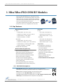
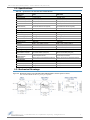
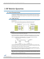
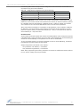
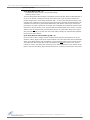
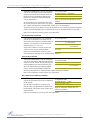
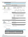
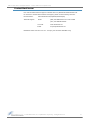
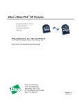
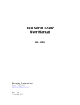
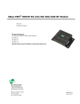
XBee™/XBee-PRO™ OEM RF Modules
XBee/XBee-PRO OEM RF Modules
RF Module Operation
RF Module Configuration
Appendices
Product Manual v1.06
For OEM RF Module Part Numbers: XB24-...-001, XB24-...-002
XBP24-...-001, XBP24-...-002
ZigBee™/IEEE® 802.15.4 OEM RF Modules by MaxStream, Inc.
355 South 520 West, Suite 180
Lindon, UT 84042
Phone: (801) 765-9885
Fax: (801) 765-9895
[email protected]
www.MaxStream.net (live chat suport)
M100232
2005.10.28
XBee™/XBee‐PRO™ OEM RF Modules ‐ Product Manual v1.06 [2005.10.28]
© 2005 MaxStream, Inc. All rights reserved
No part of the contents of this manual may be transmitted or reproduced in any form or by any means without the written permission of MaxStream, Inc.
XBee™ and XBee‐PRO™ are trademarks of MaxStream, Inc.
ZigBee™ is a registered trademark of the ZigBee Alliance.
Technical Support: Phone: (801) 765‐9885
Live Chat: www.maxstream.net
E‐mail: rf‐[email protected]
© 2005 MaxStream, Inc., Confidential & Proprietary ‐ All Rights Reserved ii
XBee™/XBee‐PRO™ OEM RF Modules – Product Manual v1.06 [2005.10.28]
Contents
1. XBee/XBee-PRO OEM RF Modules
4
1.1. Key Features 4
Appendix A: Agency Certifications
23
FCC Certification 23
1.1.1. Worldwide Acceptance 4
OEM Labeling Requirements 23
1.2. Specifications 5
FCC Notices 23
1.3. Mechanical Drawings 5
FCC-Approved Antennas (2.4 GHz) 24
1.4. Pin Signals 6
European Certification (pending) 25
1.5. Electrical Characteristics 6
OEM Labeling Requirements 25
2. RF Module Operation
7
Restrictions 25
Declarations of Conformity 25
2.1. Serial Communications 7
Appendix B: Development Guide
2.1.1. UART Data Flow 7
Development Kit Contents 26
2.1.2. Flow Control 8
Interfacing Options 26
2.2. Modes of Operation 9
RS-232 Interface Board 27
2.2.1. Idle Mode 9
2.2.2. Transmit & Receive Modes 9
Physical Interface 27
2.2.3. Sleep Mode 11
RS-232 Pin Signals 28
2.2.4. Command Mode 13
Wiring Diagrams 29
3. RF Module Configuration
14
3.1. Programming the RF Module 14
3.1.1. Programming Examples 14
3.1.2. Command Reference Tables
3.2. Command Descriptions 16
26
15
Adapters 30
USB Interface Board 31
Physical Interface 31
USB Pin Signals 31
Appendix C: Additional Information
32
1-Year Warranty 32
Ordering Information 32
Contact MaxStream 33
© 2005 MaxStream, Inc., Confidential & Proprietary ‐ All Rights Reserved iii
XBee™/XBee‐PRO OEM RF Modules – Product Manual v1.06 [2005.10.28]
1. XBee/XBee‐PRO OEM RF Modules
XBee and XBee-PRO Modules were engineered to meet
ZigBee/IEEE 802.15.4 standards and support the unique
needs of low-cost, low-power wireless sensor networks.
The modules require minimal power and provide reliable
delivery of critical data between devices.
The modules operate within the ISM 2.4 GHz frequency
band and are pin-for-pin compatible with each other.
1.1. Key Features
High Performance, Low Cost
XBee
Low Power
XBee
• Indoor/Urban: up to 100’ (30 m)
• TX Current: 45 mA (@3.3 V)
• Outdoor line-of-sight: up to 300’ (100 m)
• RX Current: 50 mA (@3.3 V)
• Transmit Power: 1 mW (0 dBm)
• Power-down Current: < 10 µA
• Receiver Sensitivity: -92 dBm
XBee-PRO
XBee-PRO
• TX Current: 270 mA (@3.3 V)
• Indoor/Urban: up to 300’ (100 m)
• RX Current: 55 mA (@3.3 V)
• Outdoor line-of-sight: up to 1 mile (1500 m)
• Power-down Current: < 10 µA
• Transmit Power: 100 mW (20 dBm) EIRP
• Receiver Sensitivity: -100 dBm
RF Data Rate: 250,000 bps
Advanced Networking & Security
Retries and Acknowledgements
DSSS (Direct Sequence Spread Spectrum)
Each direct sequence channels has over
65,000 unique network addresses available
Point-to-point, point-to-multipoint
and peer-to-peer topologies supported
Easy-to-Use
No configuration necessary for
out-of box RF communications
Free X-CTU Software
(Testing and configuration software)
AT Command Mode for simple
configuration of module parameters
Small form factor
Network compatible with other
ZigBee/802.15.4 devices
Free & Unlimited Technical Support
128-bit Encryption (downloadable firmware
version coming soon)
Self-routing/Self-healing mesh networking
(downloadable firmware version coming soon)
1.1.1. Worldwide Acceptance
FCC Approval (USA) Refer to Appendix A [p23] for FCC Requirements.
Systems that include XBee/XBee-PRO Modules inherit MaxStream’s Certifications.
ISM (Industrial, Scientific & Medical) 2.4 GHz frequency band
Manufactured under ISO 9001:2000 registered standards
XBee/XBee-PRO RF Modules are optimized for use in US, Canada, Australia, Israel
and Europe (contact MaxStream for complete list of approvals).
© 2005 MaxStream, Inc., Confidential & Proprietary ‐ All Rights Reserved 4
XBee™/XBee‐PRO OEM RF Modules – Product Manual v1.06 [2005.10.28]
1.2. Specifications
Table 1‐01.
Specifications of the XBee/XBee‐PRO OEM RF Modules
Specification
XBee
XBee-PRO
Performance
Indoor/Urban Range
up to 100 ft. (30 m)
Up to 300’ (100 m)
Outdoor RF line-of-sight Range
up to 300 ft. (100 m)
Up to 1 mile (1500 m)
Transmit Power Output
1mW (0 dBm)
60 mW (18 dBm) conducted, 100 mW (20 dBm) EIRP
RF Data Rate
250,000 bps
250,000 bps
Interface Data Rate
(software selectable)
1200 - 115200 bps
(non-standard baud rates also supported)
1200 - 115200 bps
(non-standard baud rates also supported)
Receiver Sensitivity
-92 dBm (1% packet error rate)
-100 dBm (1% packet error rate)
Supply Voltage
2.8 – 3.4 V
2.8 – 3.4 V
Transmit Current (typical)
45 mA (@ 3.3 V)
270 mA (@ 3.3 V)
Receive Current (typical)
50 mA (@ 3.3 V)
55 mA (@ 3.3 V)
Power-down Current
< 10 µA
< 10 µA
Operating Frequency
ISM 2.4 GHz
ISM 2.4 GHz
Dimensions
0.960” x 1.087” (2.438cm x 2.761cm)
0.960” x 1.297” (2.438cm x 3.294cm)
Operating Temperature
-40 to 85º C (industrial)
-40 to 85º C (industrial)
Antenna Options
U.FL Connector, Chip Antenna or Whip Antenna
U.FL Connector, Chip Antenna or Whip Antenna
Supported Network Topologies
Point-to-Point, Point-to-Multipoint,
Peer-to-Peer and Mesh (coming soon)
Point-to-Point, Point-to-Multipoint,
Peer-to-Peer and Mesh (coming soon)
Number of Channels
(software selectable)
16 Direct Sequence Channels
13 Direct Sequence Channels
Filtration Options
PAN ID, Channel and Source/Destination Addresses
PAN ID, Channel and Source/Destination Addresses
FCC Part 15.247
OUR-XBEE
pending
Industry Canada (IC)
pending
pending
Europe
pending
pending
Power Requirements
General
Networking & Security
Agency Approvals
1.3. Mechanical Drawings
Figure 1‐01. Mechanical drawings of the XBee/XBee‐PRO OEM RF Modules (antenna options not shown)
XBee and XBee‐PRO RF Modules are pin‐for‐pin compatible. © 2005 MaxStream, Inc., Confidential & Proprietary ‐ All Rights Reserved 5
XBee™/XBee‐PRO OEM RF Modules – Product Manual v1.06 [2005.10.28]
1.4. Pin Signals
Figure 1‐02. XBee/XBee‐PRO RF Module Pin Number
(top sides shown ‐ shields on bottom)
Table 1‐02.
Pin Assignments for the XBee and XBee‐PRO Modules
(Low‐asserted signals are distinguished with a horizontal line above signal name.)
Pin #
Name
Direction
Description
1
VCC
-
Power supply
2
DOUT
Output
UART Data Out
3
DIN / CONFIG
Input
UART Data In
4
CD* / DOUT_EN* / DO8*
Output
Carrier Detect, TX_enable or Digital Output 8
5
RESET
Input
Module Reset
6
PWM0 / RSSI
Output
PWM Output 0 or RX Signal Strength Indicator
7
[reserved]
-
Do not connect
8
[reserved]
-
Do not connect
Pin Sleep Control Line or Digital Input 8
9
DTR / SLEEP_RQ / DI8
Input
10
GND
-
Ground
11
RF_TX* / AD4* / DIO4*
Either
Transmission Indicator, Analog Input 4 or Digital I/O 4
12
CTS* / DIO7*
Either
Clear-to-Send Flow Control or Digital I/O 7
13
ON / SLEEP
Output
Module Status Indicator
14
VREF*
Input
Voltage Reference for A/D Inputs
15
Associate / AD5* / DIO5*
Either
Associated Indicator, Analog Input 5 or Digital I/O 5
16
RTS* / AD6* / DIO6*
Either
Request-to-Send Flow Control, Analog Input 6 or Digital I/O 6
17
COORD_SEL* / AD3* / DIO3*
Either
Analog Input 3, Digital I/O 3 or Coordinator Select
18
AD2* / DIO2*
Either
Analog Input 2 or Digital I/O 2
19
AD1* / DIO1*
Either
Analog Input 1 or Digital I/O 1
20
AD0* / DIO0*
Either
Analog Input 0 or Digital I/O 0
* Functions not supported at the time of this release.
Design Notes:
• Minimum connections are: VCC, GND, DOUT and DIN
• Signal Direction is specified with respect to the module
• Module includes a 50k pull-up resistor attached to RESET
• Unused pins should be left disconnected.
1.5. Electrical Characteristics
Table 1‐03.
Symbol
DC Characteristics of the XBee & XBee‐PRO (VCC = 2.8 ‐ 3.4 VDC)
Parameter
Condition
VIL
Min
Typical
Max
Input Low Voltage
All Digital Inputs
VIH
Input High Voltage
All Digital Inputs
VOL
Output Low Voltage
IOL = 2 mA, VCC >= 2.7 V
-
Units
-
-
0.35 * VCC
V
0.7 * VCC
-
-
V
-
0.5
V
VOH
Output High Voltage
IOH = -2 mA, VCC >= 2.7 V
VCC - 0.5
-
-
V
IIIN
Input Leakage Current
VIN = VCC or GND, all inputs, per pin
-
0.025
1
uA
IIOZ
High Impedance Leakage Current
VIN = VCC or GND, all I/O High-Z, per pin
-
0.025
TX
Transmit Current
VCC = 3.3 V
-
45
(XBee)
RX
Receive Current
VCC = 3.3 V
-
50
(XBee)
PWR-DWN
Power-down Current
SM parameter = 1
-
© 2005 MaxStream, Inc., Confidential & Proprietary ‐ All Rights Reserved < 10
1
uA
270
(PRO)
-
mA
55
(PRO)
-
mA
-
uA
6
XBee™/XBee‐PRO OEM RF Modules – Product Manual v1.06 [2005.10.28]
2. RF Module Operation
2.1. Serial Communications
The XBee/XBee-PRO OEM RF Modules interface to a host device through a logic-level asynchronous serial port. Through its serial port, the module can communicate with any logic and voltage
compatible UART; or through a level translator to any serial device (For example: RS-232/485/
422 or USB interface board).
2.1.1. UART Data Flow
Devices that have a UART interface can connect directly to the pins of the RF module as shown in
the figure below.
Figure 2‐01. Figure 2‐01.System Data Flow Diagram in a UART‐interfaced environment
(Low‐asserted signals distinguished with horizontal line over signal name.)
Serial Data
Data enters the module UART through the DI pin (pin 3) as an asynchronous serial signal. The signal should idle high when no data is being transmitted.
Each data byte consists of a start bit (low), 8 data bits (least significant bit first) and a stop bit
(high). The following figure illustrates the serial bit pattern of data passing through the module.
Figure 2‐02. UART data packet 0x1F (decimal number ʺ31ʺ) as transmitted through the RF module
Example Data Format is 8‐N‐1 (bits ‐ parity ‐ # of stop bits)
The module UART performs tasks, such as timing and parity checking, that are needed for data
communications. Serial communications depend on the two UARTs to be configured with compatible settings (baud rate, parity, start bits, stop bits, data bits)
Both the module and host (PC) settings can be viewed and adjusted using MaxStream's proprietary X-CTU Software. Use the "PC Settings" tab to configure host settings. Use the "Terminal" or
"RF Module Configuration" tab to configure the module settings.
NOTE: Failure to enter AT Command Mode is most commonly due to baud rate mismatch. Ensure the
‘Baud’ setting on the “PC Settings” tab matches the interface data rate of the RF module (by default, BD
parameter = 3 (which is associated to 9600 bps)).
© 2005 MaxStream, Inc., Confidential & Proprietary ‐ All Rights Reserved 7
XBee™/XBee‐PRO OEM RF Modules – Product Manual v1.06 [2005.10.28]
2.1.2. Flow Control
Figure 2‐03. Internal Data Flow Diagram
DI (Data In) Buffer
When serial data enters the RF module through the DI pin (pin 3), the data is stored in the DI
Buffer until it can be processed.
Hardware Flow Control (CTS). When the DI buffer is 17 bytes away from being full; by default,
the module de-asserts CTS (high) to signal to the host device to stop sending data [refer to D7
(DIO7 Configuration) parameter]. CTS is re-asserted after the DI Buffer has 34 bytes of memory
available.
How to eliminate the need for flow control:
1.
Send messages that are smaller than the DI buffer size.
2.
Interface at a lower baud rate [BD (Interface Data Rate) parameter] than the throughput
data rate.
Case in which the DI Buffer may become full and possibly overflow:
If the module is receiving a continuous stream of RF data, any serial data that arrives on the DI
pin is placed in the DI Buffer. The data in the DI buffer will be transmitted over-the-air when the
module is no longer receiving RF data in the network.
NOTE: CTS hardware flow control is not supported in this release (v1.06). Contact MaxStream support
to download firmware that supports this function.
DO (Data Out) Buffer
When RF data is received, the data enters the DO buffer and is sent out the serial port to a host
device. Once the DO Buffer reaches capacity, any additional incoming RF data is lost.
Hardware Flow Control (RTS). If RTS is enabled for flow control (D6 (DIO6 Configuration)
Parameter = 1), data will not be sent out the DO Buffer as long as RTS (pin 16) is de-asserted.
Two cases in which the DO Buffer may become full and possibly overflow:
1.
If the RF data rate is set higher than the interface data rate of the module, the module will
receive data from the transmitting module faster than it can send the data to the host.
2.
If the host does not allow the module to transmit data out from the DO buffer because of
being held off by hardware or software flow control.
NOTE: RTS hardware flow control is not supported in this release (v1.06). Contact MaxStream support
to download firmware that supports this function.
© 2005 MaxStream, Inc., Confidential & Proprietary ‐ All Rights Reserved 8
XBee™/XBee‐PRO OEM RF Modules – Product Manual v1.06 [2005.10.28]
2.2. Modes of Operation
XBee/XBee-PRO RF Modules operate in five modes.
Figure 2‐04. XBee/XBee‐PRO RF Module Modes of Operation
2.2.1. Idle Mode
When not receiving or transmitting data, the RF module is in Idle Mode. The RF module shifts into
the other modes of operation under the following conditions:
• Transmit Mode: Serial data is received in the DI Buffer
• Receive Mode: Valid RF data is received through the antenna
• Sleep Mode: Sleep Mode condition is met
• Command Mode: Command Mode Sequence is issued
2.2.2. Transmit & Receive Modes
Addressing
When communication occurs between two networked devices, each data packet contains a
<Source Address> and a <Destination Address> field. The XBee/XBee-PRO RF Module conforms
to the 802.15.4 specification and supports both short 16-bit addresses and long 64-bit addresses.
A unique 64-bit IEEE source address is assigned at the factory and can be read with the SL (Serial
Number Low) and SH (Serial Number High) parameters. Short addressing must be configured
manually. An RF module will use its unique 64-bit address as its Source Address if its MY value is
“0xFFFF” or “0xFFFE”.
To send a packet to a specific RF module using 64-bit addressing, set the Destination Address (DL
+ DH) to match the Source Address (SL + SH) of the intended destination RF module. To send a
packet to a specific RF module using 16-bit addressing, set the DL (Destination Address Low)
parameter to the MY (Source Address) parameter and set the DH (Destination Address High)
parameter to “0”.
Unicast Mode
Unicast Mode enables acknowledged communications. While in this mode, receiving modules send
an ACK (acknowledgement) of RF packet reception to the transmitter. If the transmitting module
does not receive the ACK, the transmitter will re-send the packet up to three times until the ACK is
received.
Unicast Mode is the only mode that supports retries.
Short 16-bit addresses. The module can be configured to use short 16-bit addresses as the
Source Address by setting (MY < 0xFFFE). Setting the DH parameter (DH = 0) will configure the
Destination Address to be a short 16-bit address (if DL < 0xFFFE). For two modules to communicate using short addressing, the Destination Address of the transmitter module must match the
MY parameter of the receiver.
© 2005 MaxStream, Inc., Confidential & Proprietary ‐ All Rights Reserved 9
XBee™/XBee‐PRO OEM RF Modules – Product Manual v1.06 [2005.10.28]
The following table shows a sample network configuration that would enable Unicast Mode communications using 16-bit short addresses.
Table 2‐01.
Sample Unicast Configuration (using 16‐bit addressing)
Parameter
RF Module 1
RF Module 2
MY (Source Address)
0x01
0x02
DH (Destination Address High)
0
0
DL (Destination Address Low)
0x02
0x01
Long 64-bit addresses. The RF module’s serial number (SL parameter concatenated to the SH
parameter) can be used as a 64-bit source address when the MY (16-bit Source Address) parameter is disabled. When the MY parameter is disabled (set MY = 0xFFFF or 0xFFFE), the module’s
source address is set to the 64-bit IEEE address stored in the SH and SL parameters.
When an End Device associates to a Coordinator, its MY parameter is set to 0xFFFE to enable 64bit addressing. The 64-bit address of the module is stored as SH and SL parameters. To send a
packet to a specific module, the Destination Address (DL + DH) on one module must match the
Source Address (SL + SH) of the other.
Broadcast Mode
Any RF module will accept a packet that contains a broadcast address. When configured to operate
in Broadcast Mode, receiving modules do not send ACKs (Acknowledgements) and transmitting RF
modules do not automatically re-send packets as is the case in Unicast Mode.
To send a broadcast packet to all modules regardless of 16-bit or 64-bit addressing, set destination addresses of all the modules as shown below.
Sample Configuration (All modules in the network):
• DL (Destination Low Address) = 0x0000FFFF
• DH (Destination High Address) = 0x00000000
NOTE: When programming the module, parameters are entered in hexadecimal notation (without
the “0x” prefix). Leading zeros may be omitted.
© 2005 MaxStream, Inc., Confidential & Proprietary ‐ All Rights Reserved 10
XBee™/XBee‐PRO OEM RF Modules – Product Manual v1.06 [2005.10.28]
2.2.3. Sleep Mode
Sleep Modes enable the RF module to enter states of low-power consumption when not in use. In
order to enter Sleep Mode, one of the following conditions must be met (in addition to the module
having a non-zero SM parameter value):
• Sleep_RQ (pin 9) is asserted.
• The module is idle (no data transmission or reception) for the amount of time defined by the
ST (Time before Sleep) parameter. [NOTE: ST is only active when SM = 4-5.]
Table 2‐02.
Sleep Mode Configurations
Sleep Mode Transition into
Setting
Sleep Mode
Transition out of
Sleep Mode (wake)
Characteristics
Related
Commands
Power
Consumption
Pin Hibernate
(SM = 1)
Assert (high) Sleep_RQ
(pin 9)
De-assert (low) Sleep_RQ
Pin/Host-controlled /
NonBeacon systems (SM)
only / Lowest Power
< 10 µA (@3.0
VCC)
Pin Doze
(SM = 2)
Assert (high) Sleep_RQ
(pin 9
De-assert (low) Sleep_RQ
Pin/Host-controlled /
NonBeacon systems
(SM)
only / Fastest Wakeup
< 50 µA
Cyclic Sleep
(SM = 4 - 5)
Automatic transition to
Sleep Mode as defined by
the SM (Sleep Mode) and
ST (Time before Sleep)
parameters.
Transition occurs after the
cyclic sleep time interval
elapses. The time interval
is defined by the SP (Cyclic
Sleep Period) parameter.
RF Module wakes in
pre-determined time
intervals to detect if
RF data is present / (SM), SP, ST
When SM = 5,
NonBeacon systems
only
< 50 µA
when sleeping
The SM command is central to setting Sleep Mode configurations. By default, Sleep Modes are disabled (SM = 0) and the module remains in Idle/Receive Mode. When in this state, the module is
constantly ready to respond to serial or RF activity.
Pin/Host-controlled Sleep Modes
Pin Hibernate (SM = 1)
• Pin/Host-controlled
• Typical power-down current: < 10 µA (@3.0 VCC)
• Wake-up time: 13.2 msec
Pin Hibernate Mode minimizes quiescent power (power consumed when in a state of rest or inactivity). This mode is voltage level-activated; when Sleep_RQ is asserted, the module will finish any
transmit, receive or association activities, enter Idle Mode and then enter a state of sleep. The
module will not respond to either serial or RF activity while in pin sleep.
To wake a sleeping module operating in Pin Hibernate Mode, de-assert Sleep_RQ (pin 9). The
module will wake when Sleep_RQ is de-asserted and is ready to transmit or receive when the CTS
line is low.
Pin Doze (SM = 2)
• Pin/Host-controlled
• Typical power-down current: < 50 µA
• Wake-up time: 2 msec
Pin Doze Mode functions as does Pin Hibernate Mode; however, Pin Doze features faster wake-up
time and higher power consumption.
© 2005 MaxStream, Inc., Confidential & Proprietary ‐ All Rights Reserved 11
XBee™/XBee‐PRO OEM RF Modules – Product Manual v1.06 [2005.10.28]
Cyclic Sleep Modes
Cyclic Sleep Remote (SM = 4)
• Typical Power-down Current: < 50 µA (when asleep)
• Wake-up time: 2 msec
The Cyclic Sleep Modes allow modules to periodically check for RF data. When the SM parameter is
set to ‘4’, the module is configured to sleep, then wakes once a cycle to check for data from a
module configured as a Cyclic Sleep Coordinator (SM = 6). The Cyclic Sleep Remote sends a poll
request to the coordinator at a specific interval set by the SP (Cyclic Sleep Period) parameter. The
coordinator will transmit any queued data addressed to that specific remote upon receiving the
poll request. If no data is queued for the remote, the coordinator will not transmit and the remote
will return to sleep for another cycle. If queued data is transmitted back to the remote, it will stay
awake to allow for back and forth communication until the ST (Time before Sleep) timer expires.
Also note that CTS will go low each time the remote wakes, allowing for communication initiated
by the remote host if desired.
Cyclic Sleep Remote with Pin Wake-up (SM = 5)
Use this mode to wake a sleeping remote module through either the RF interface or by the deassertion of Sleep_RQ for event-driven communications. The cyclic sleep mode works as described
above (Cyclic Sleep Remote) with the addition of a pin-controlled wake-up at the remote module.
The module will wake quickly when a low is detected and set CTS low as soon as it is ready to
transmit or receive. Any activity will reset the ST (Time before Sleep) timer so the module will go
back to sleep only after Sleep_RQ is asserted and there is no activity for the duration of the timer.
© 2005 MaxStream, Inc., Confidential & Proprietary ‐ All Rights Reserved 12
XBee™/XBee‐PRO OEM RF Modules – Product Manual v1.06 [2005.10.28]
2.2.4. Command Mode
To modify or read RF Module parameters, the module must first enter into Command Mode - a
state in which incoming characters are interpreted as commands. Two command modes are supported: AT Command Mode and ATI Command Mode.
A robust set of AT Commands is available for programming and customizing the module.
AT Command Mode
To Enter AT Command Mode:
Send the 3-character command sequence “+++” and observe guard times before and after the
command characters. [Refer to the “Default AT Command Mode Sequence” below.]
Default AT Command Mode Sequence (for transition to Command Mode):
• No characters sent for one second [GT (Guard Times) parameter = 0x3E8]
• Input three plus characters (“+++”) within one second [CC (Command Sequence Character)
parameter = 0x2B.]
• No characters sent for one second [GT (Guard Times) parameter = 0x3E8]
All of the parameter values in the sequence can be modified to reflect user preferences.
To Send AT Commands:
Send AT commands and parameters using the syntax shown below.
Figure 2‐05. Syntax for sending AT Commands To read a parameter value stored in the RF module’s register, leave the parameter field blank.
The preceding example would change the RF module Destination Address (Low) to “0x1F”. To
store the new value to non-volatile (long term) memory, subsequently send the WR (Write) command.
For modified parameter values to persist in the module’s registry, changes must be saved to nonvolatile memory using the WR (Write) Command. Otherwise, parameters are restored to previously saved values after the module is powered off and then on again (or re-booted).
System Response. When a command is sent to the RF module, the module will parse and execute the command. Upon successful execution of a command, the module returns an “OK” message. If execution of a command results in an error, the module returns an “ERROR” message.
To Exit AT Command Mode:
1.
Send ATCN (Exit Command Mode) Command.
2.
If no valid AT Commands are received within the time specified by CT (Command Mode
Timeout) Command, the RF module automatically returns to Idle Mode.
[OR]
For an example of programming the RF module using AT Commands and descriptions of each configurable parameter, refer to the "RF Module Configuration" chapter [p14].
© 2005 MaxStream, Inc., Confidential & Proprietary ‐ All Rights Reserved 13
XBee™/XBee‐PRO™ OEM RF Modules – Product Manual v1.06 [2005.10.28]
3. RF Module Configuration
3.1. Programming the RF Module
Refer to the “Command Mode” section [p13] for more information about entering Command Mode,
sending AT commands and exiting Command Mode.
3.1.1. Programming Examples
Setup
The programming examples in this section require the installation of MaxStream's X-CTU Software and a serial connection to a PC. (MaxStream stocks RS-232 and USB boards to facilitate
interfacing to a PC.)
1.
Install MaxStream's X-CTU Software to a PC by double-clicking the "setup_X-CTU.exe" file.
(The file is located on the MaxStream CD and under the 'Software' section of the following
web page: www.maxstream.net/helpdesk/download.php)
2.
Mount the RF module to an interface board, then connect the module assembly to a PC.
3.
Launch the X-CTU Software and select the 'PC Settings' tab. Verify the baud and parity settings of the Com Port match those of the RF module.
NOTE: Failure to enter AT Command Mode is most commonly due to baud rate mismatch.
Ensure the ‘Baud’ setting on the ‘PC Settings’ tab matches the interface data rate of the RF module (by default, BD parameter = 3 (which corresponds to 9600 bps)).
Sample Configuration: Modify RF Module Destination Address
Example: Utilize the 'Terminal' tab of the X-CTU Software to change the RF module's DL (Destination Address Low) parameter and save the new address to non-volatile memory.
After establishing a serial connection between the RF module and a PC [refer to the 'Setup' section above], select the ‘Terminal’ tab of the X-CTU Software and enter the following command
lines (‘CR’ stands for carriage return):
Method 1 (One line per command)
Send AT Command
+++
ATDL <Enter>
ATDL1A0D <Enter>
ATWR <Enter>
ATCN <Enter>
System Response
OK <CR> (Enter into Command Mode)
{current value} <CR> (Read Destination Address Low)
OK <CR> (Modify Destination Address Low)
OK <CR> (Write to non-volatile memory)
OK <CR> (Exit Command Mode)
Method 2 (Multiple commands on one line)
Send AT Command
+++
ATDL <Enter>
ATDL1A0D,WR,CN <Enter>
System Response
OK <CR> (Enter into Command Mode)
{current value} <CR> (Read Destination Address Low)
OK <CR> (Execute commands)
Sample Configuration: Restore RF Module Defaults
Example: Utilize the 'Modem Configuration' tab of the X-CTU Software to restore default parameter values of the RF module.
After establishing a connection between the RF module and a PC [refer to the 'Setup' section
above], select the 'Modem Configuration' tab of the X-CTU Software.
1.
Select the 'Read' button.
2.
Select the 'Restore' button.
© 2005 MaxStream, Inc., Confidential & Proprietary ‐ All Rights Reserved 14
XBee™/XBee‐PRO™ OEM RF Modules – Product Manual v1.06 [2005.10.28]
3.1.2.
Table 3‐01.
Command Reference Tables
XBee/XBee‐PRO Commands (RF modules expect numerical values in hexadecimal. Hexadecimal values are designated by the “0x” prefix. Decimal equivalents are designated by the “d” suffix.)
AT
Command
Command
Category
Name and Description
Parameter Range
Default
BD
Serial Interfacing
Interface Data Rate. Set/Read the serial interface data rate for communications
between the RF module serial port and host.
0-7
(custom rates also supported)
3
CC
AT Command
Mode Options
Command Sequence Character. Set/Read the ASCII character value to be used
between Guard Times of the AT Command Mode Sequence (GT+CC+GT). The AT
Command Mode Sequence enters the RF module to AT Command Mode.
0 - 0xFF
0x2B
('+' ASCII)
CH
Networking &
Security
Channel. Set/Read the channel number used for transmitting and receiving between
RF modules. Uses 802.15.4 protocol channel numbers.
0x0B - 0x1A (XBee)
0x0C - 0x18 (XBee-PRO)
0x0C (12d)
CN
AT Command
Mode Options
Exit Command Mode. Explicitly exit AT Command Mode.
-
-
CT
AT Command
Mode Options
Command Mode Timeout. Set/Read the period of inactivity (no valid commands
received) after which the RF module automatically exits AT Command Mode and
returns to Idle Mode.
2 - 0xFFFF [x 100 ms]
0x64 (100d)
DB
Diagnostics
Received Signal Strength. Read signal level [in dB] of last good packet received
(RSSI). Absolute value is reported. (For example: 0x58 = -88 dBm) Reported value is
accurate between -40 dBm and RX sensitivity.
0 - 0x64 [read-only]
-
DH
Networking
& Security
Destination Address High. Set/Read the upper 32 bits of the 64-bit destination
address. When combined with DL, it defines the destination address used for
0 - 0xFFFFFFFF
transmission. To transmit using a 16-bit address, set DH parameter to zero and DL less
than 0xFFFF. 0x000000000000FFFF is the broadcast address for the PAN.
0
DL
Networking &
Security
Destination Address Low. Set/Read the lower 32 bits of the 64-bit destination
address. When combined with DH, DL defines the destination address used for
0 - 0xFFFFFFFF
transmission. To transmit using a 16-bit address, set DH parameter to zero and DL less
than 0xFFFF. 0x000000000000FFFF is the broadcast address for the PAN.
0
GT
AT Command
Mode Options
Guard Times. Set required period of silence before and after the Command Sequence
Characters of the AT Command Mode Sequence (GT+ CC + GT). The period of silence 0x02 - 0xFFFF [x 1 ms]
is used to prevent inadvertent entrance into AT Command Mode.
0x3E8
(1000d)
ID
Networking &
Security
PAN ID. Set/Read the PAN (Personal Area Network) ID.
0xFFFF indicates a message for all PANs.
0xFFFF
0x3332
(13106d)
MY
Networking &
Security
16-bit Source Address. Set/Read the RF module 16-bit source address. Set MY =
0xFFFF to disable reception of packets with 16-bit addresses. 64-bit source address
(serial number) and broadcast address (0x000000000000FFFF) is always enabled.
0 - 0xFFFF
0
P0
Diagnostics
PWM0 Configurations. Select/Read function for PWM0.
0-1
1
PL
RF Interfacing
Power Level. Select/Read power level at which the RF module transmits.
0-4
4
RE
(Special)
Restore Defaults. Restore RF module parameters to factory defaults. Follow with WR
command to save values to non-volatile memory.
-
RN
Networking &
Security
Random Delay Slots. Set/Read the minimum value of the back-off exponent in the
CSMA-CA algorithm that is used for collision avoidance. If RN = 0, collision avoidance
is disabled during the first iteration of the algorithm (802.15.4 - macMinBE).
0
RO
Packetization Timeout. Set/Read number of character times of inter-character delay
Serial Interfacing required before transmission. Set to zero to transmit characters as they arrive instead of 0 - 0xFF [x character times]
buffering them into one RF packet.
RP
Diagnostics
RSSI PWM Timer. Enable a PWM (pulse width modulation) output (on pin 3 of the RF
modules) which shows RX signal strength.
0 - 0xFF [x 100 ms]
0x28 (40d)
SH
Diagnostics
Serial Number High. Read high 32 bits of the RF module's unique IEEE 64-bit
address. 64-bit source address is always enabled.
0 - 0xFFFFFFFF [read-only]
Factory-set
SL
Diagnostics
Serial Number Low. Read low 32 bits of the RF module's unique IEEE 64-bit address.
0 - 0xFFFFFFFF [read-only]
64-bit source address is always enabled.
Factory-set
SM
Sleep
(Low Power)
Sleep Mode. Set/Read Sleep Mode configurations.
0-5
0
SP
Sleep
(Low Power)
Cyclic Sleep Period. Set/Read sleep period for cyclic sleeping remotes. Maximum
sleep period is 268 seconds (0x68B0).
0x01 - 0x68B0 [x 10 ms]
0x64 (100d)
ST
Sleep
(Low Power)
Time before Sleep. Set/Read time period of inactivity (no serial or RF data is sent or
received) before activating Sleep Mode. The ST parameter is only valid with Cyclic
Sleep settings (SM = 4 - 6). Set ST on Cyclic Sleep Coordinator to match Cyclic Sleep
Remotes.
0x01 - 0xFFFF [x 1 ms]
0x1388
(5000d)
VR
Diagnostics
Firmware Version. Read firmware version of the RF module.
0 - 0xFFFF [read-only]
Factory-set
(Special)
Write. Write parameter values to RF module's non-volatile memory so that
modifications persist through subsequent power-up or reset.
-
-
WR
0-3
© 2005 MaxStream, Inc., Confidential & Proprietary ‐ All Rights Reserved 3
15
XBee™/XBee‐PRO™ OEM RF Modules – Product Manual v1.06 [2005.10.28]
3.2. Command Descriptions
Command descriptions in this section are listed alphabetically. Command categories are designated within "< >" symbols that follow each command title. XBee-PRO RF modules expect parameter values in hexadecimal (designated by the "0x" prefix).
BD (Interface Data Rate) Command
<Serial Interfacing> The BD command is used to
set and read the serial interface data rate (baud
rate) used between the RF module and host. This
parameter determines the rate at which serial
data is sent to the RF module from the host. Modified interface data rates do not take effect until
the CN (Exit AT Command Mode) command is
issued and the system returns the 'OK' response.
AT Command: ATBD
Parameter Range: 0 - 7 (standard rates)
When parameters 0-7 are sent to the RF module,
the respective interface data rates are used (as
shown in the table on the right).
The RF data rate is not affected by the BD parameter. If the interface data rate is set higher than
the RF data rate, a flow control configuration may
need to be implemented.
Parameter
Configuration (bps)
0
1200
1
2400
2
4800
3
9600
4
19200
5
38400
6
57600
7
115200
Default Parameter Value:3
Non-standard Interface Data Rates:
When parameter values outside the range of standard baud rates are sent, the closest interface
data rate represented by the number is stored in the BD register. For example, a rate of 19200
bps can be set by sending the following command line "ATBD4B00". NOTE: When using MaxStream’s X-CTU Software, non-standard interface data rates can only be set and read using the XCTU ‘Terminal’ tab. Non-standard rates are not accessible through the ‘Modem Configuration’ tab.
When the BD command is sent with a non-standard interface data rate, the UART will adjust to
accommodate the requested interface rate. In most cases, the clock resolution will cause the
stored BD parameter to vary from the parameter that was sent (refer to the table below). Reading
the BD command (send "ATBD" command without an associated parameter value) will return the
value that was actually stored to the BD register.
Table 3‐02.
Parameters Sent Versus Parameters Stored
BD Parameter Sent (HEX)
Interface Data Rate (bps)
0
1200
BD Parameter Stored (HEX)
0
4
19,200
4
7
115,200
7
12C
300
12B
1C200
115,200
1B207
CC (Command Sequence Character) Command
<AT Command Mode Options> The CC command
is used to set and read the ASCII character used
between guard times of the AT Command Mode
Sequence (GT + CC + GT). This sequence enters
the RF module into AT Command Mode so that
data entering the modem from the host is recognized as commands instead of payload.
AT Command: ATCC
Parameter Range: 0 - 0xFF
Default Parameter Value: 0x2B (ASCII “+”)
Related Commands: GT (Guard Times)
Refer to the Command Mode section [p13] for more information regarding the AT Command Mode
Sequence.
© 2005 MaxStream, Inc., Confidential & Proprietary ‐ All Rights Reserved 16
XBee™/XBee‐PRO™ OEM RF Modules – Product Manual v1.06 [2005.10.28]
CH (Channel) Command
<Networking {Addressing}> The CH command is
used to set and read the channel on which RF
connections are made between RF modules. The
channel is one of three filtration layers available
to the RF module. The other layers are the PAN
ID (ID command) and destination addresses (DL
& DH commands).
AT Command: ATCH
Parameter Range: 0x0B - 0x1A (XBee)
0x0C - 0x18 (XBee-PRO)
Default Parameter Value: 0x0C (12 decimal)
Related Commands: ID (PAN ID), DL
(Destination Address Low, DH (Destination
Address High)
In order for RF modules to communicate with
each other, the RF modules must share the same channel number. Different channels can be used
to prevent RF modules in one network from listening to transmissions of another.
The RF module uses channel numbers of the 802.15.4 standard.
Center Frequency = 2.405 + (CH - 11d) * 5 MHz
(d = decimal)
Refer to the “Addressing” section [p9] for more information.
CN (Exit AT Command Mode) Command
<AT Command Mode Options> The CN command
is used to explicitly exit the RF module from AT
Command Mode.
AT Command: ATCN
CT (Command Mode Timeout) Command
<AT Command Mode Options> The CT command
is used to set and read the amount of inactive
time that elapses before the RF module automatically exits from AT Command Mode and returns
to Idle Mode.
Use the CN (Exit AT Command Mode) command
to exit AT Command Mode manually.
AT Command: ATCT
Parameter Range: 2 - 0xFFFF
[x 100 milliseconds]
Default Parameter Value: 0x64 (100 decimal,
which equals 10 decimal seconds)
Number of bytes returned: 2
Related Command: CN (Exit AT Command
Mode)
DB (Received Signal Strength) Command
<Diagnostics> DB parameter is used to read the
AT Command: ATDB
received signal strength (in dBm) of the last RF
Parameter Range: 0 - 0x64 [read-only]
packet received. Reported values are accurate
between -40 dBm and the RF module's receiver sensitivity.
Absolute values are reported. For example: 0x58 = -88 dBm (decimal). If no packets have been
received (since last reset, power cycle or sleep event), “0” will be reported.
DH (Destination Address High) Command
<Networking {Addressing}> The DH command is
used to set and read the upper 32 bits of the RF
module's 64-bit destination address. When combined with the DL (Destination Address Low)
parameter, it defines the destination address
used for transmission.
AT Command: ATDH
Parameter Range: 0 - 0xFFFFFFFF
Default Parameter Value: 0
Related Commands: DL (Destination Address
Low), CH (Channel), ID (PAN VID), MY (Source
Address)
An RF module will only communicate with other
RF modules having the same channel (CH parameter), PAN ID (ID parameter) and destination address
(DH + DL parameters).
To transmit using a 16-bit address, set the DH parameter to zero and the DL parameter less than
0xFFFF. 0x000000000000FFFF (DL concatenated to DH) is the broadcast address for the PAN.
Refer to the “Addressing” section [p9] for more information.
© 2005 MaxStream, Inc., Confidential & Proprietary ‐ All Rights Reserved 17
XBee™/XBee‐PRO™ OEM RF Modules – Product Manual v1.06 [2005.10.28]
DL (Destination Address Low) Command
<Networking {Addressing}> The DL command is
used to set and read the lower 32 bits of the RF
module's 64-bit destination address. When combined with the DH (Destination Address High)
parameter, it defines the destination address
used for transmission.
AT Command: ATDL
Parameter Range: 0 - 0xFFFFFFFF
Default Parameter Value: 0
Related Commands: DH (Destination Address
High), CH (Channel), ID (PAN VID), MY (Source
Address)
An RF module will only communicate with other
RF modules having the same channel (CH parameter), PAN ID (ID parameter) and destination address (DH + DL parameters).
To transmit using a 16-bit address, set the DH parameter to zero and the DL parameter less than
0xFFFF. 0x000000000000FFFF (DL concatenated to DH) is the broadcast address for the PAN.
Refer to the “Addressing” section [p9] for more information.
GT (Guard Times) Command
<AT Command Mode Options> GT Command is
used to set the DI (data in from host) time-ofsilence that surrounds the AT command sequence
character (CC Command) of the AT Command
Mode sequence (GT + CC + GT).
The DI time-of-silence is used to prevent inadvertent entrance into AT Command Mode.
AT Command: ATGT
Parameter Range: 2 - 0xFFFF
[x 1 millisecond]
Default Parameter Value: 0x3E8
(1000 decimal)
Related Command: CC (Command Sequence
Character)
Refer to the Command Mode section [p13] for
more information regarding the AT Command Mode Sequence.
ID (Pan ID) Command
<Networking {Addressing}> The ID command is
used to set and read the PAN (Personal Area Network) ID of the RF module. Only RF modules with
matching PAN IDs can communicate with each
other. RF modems with non-matching PAN IDs
will not receive unintended data transmission.
AT Command: ATID
Parameter Range: 0 - 0xFFFF
Default Parameter Value:0x3332
(13106 decimal)
Setting the ID parameter to 0xFFFF indicates a global message for all PANs.
Refer to the “Addressing” section [p9] for more information.
MY (16-bit Source Address) Command
<Networking {Addressing}> The MY command is
used to set and read the 16-bit source address of
the RF module.
By setting MY to 0xFFFF, the reception of RF
packets having a 16-bit address is disabled. The
64-bit address is the module serial number and is
always enabled.
AT Command: ATMY
Parameter Range: 0 - 0xFFFF
Default Parameter Value: 0
Related Commands: DH (Destination Address
High), DL (Destination Address Low), CH
(Channel), ID (PAN ID)
Refer to the “Addressing” section [p9] for more information.
© 2005 MaxStream, Inc., Confidential & Proprietary ‐ All Rights Reserved 18
XBee™/XBee‐PRO™ OEM RF Modules – Product Manual v1.06 [2005.10.28]
P0 (PWM0 Configuration) Command
<Diagnostics> The P0 command is used to select
and read the function for PWM0 (Pulse Width
Modulation output 0 - pin 6).
Note: The second character in the command is a
zero (“0”), not the letter “O”.
AT Command: ATP0
Parameter Range: 0 - 1
Parameter
Configuration
0
Disabled
1
RSSI PWM0 enabled
Default Parameter Value: 1
PL (Power Level) Command
<RF Interfacing> The PL command is used to
select and read the power level at which the RF
module transmits conducted power.
AT Command: ATPL
Parameter Range: 0 - 4
Parameter
XBee
XBee-Pro
0
-10 dBm
10 dBm
1
-6 dBm
12 dBm
2
-4 dBm
14 dBm
3
-2 dBm
16 dBm
4
0 dBm
18 dBm
Default Parameter Value: 4
RE (Restore Defaults) Command
<(Special)> The RE command is used to restore
AT Command: ATRE
all configurable parameters to their factory
default settings. The RE command does not write
restored values to non-volatile (persistent) memory. Issue the WR (Write) command subsequent
to issuing the RE command to save restored parameter values to non-volatile memory.
RN (Random Delay Slots) Command
<Networking & Security> The RN command is
used to set and read the minimum value of the
back-off exponent in the CSMA-CA algorithm. The
CSMA-CA algorithm was engineered for collision
avoidance (random delays are inserted to prevent
data loss caused by data collisions).
AT Command: ATRN
Parameter Range: 0 - 3 [exponent]
Default Parameter Value: 0
If RN = 0, collision avoidance is disabled during the first iteration of the algorithm (802.15.4 macMinBE).
CSMA-CA stands for "Carrier Sense Multiple Access - Collision Avoidance". Unlike CSMA-CD (reacts
to network transmissions after collisions have been detected), CSMA-CA acts to prevent data collisions before they occur. As soon as a modem receives a packet that is to be transmitted, it checks
if the channel is clear (no other modem is transmitting). If the channel is clear, the packet is sent
over-the-air. If the channel is not clear, the RF module waits for a randomly selected period of
time, then checks again to see if the channel is clear. After a time, the process ends and the data
is lost.
© 2005 MaxStream, Inc., Confidential & Proprietary ‐ All Rights Reserved 19
XBee™/XBee‐PRO™ OEM RF Modules – Product Manual v1.06 [2005.10.28]
RO (Packetization Timeout) Command
<Serial Interfacing> RO command is used to set
and read the number of character times of intercharacter delay required before transmission.
AT Command: ATRO
Parameter Range: 0 - 0xFF
[x character times]
RF transmission commences when data is
Default Parameter Value: 3
detected in the DI (data in from host) buffer and
RO character times of silence are detected on the
UART receive lines (after receiving at least 1 byte).
RF transmission will also commence after 100 bytes (maximum packet size) are received in the DI
buffer.
Set the RO parameter to '0' to transmit characters as they arrive instead of buffering them into
one RF packet.
RP (RSSI PWM Timer) Command
<Diagnostics> The RP command is used to
AT Command: ATRP
enable PWM (Pulse Width Modulation) output on
Parameter Range: 0 - 0xFF
the RF module. The output is calibrated to show
[x 100 milliseconds]
the level a received RF signal is above the sensiDefault Parameter Value: 0x28 (40 decimal)
tivity level of the RF module. The PWM pulses
vary from zero to 95 percent. Zero to twenty-nine
percent means the received RF signal is at or below the published sensitivity level of the RF module. The following table shows levels above sensitivity and PWM values.
The total period of the PWM output is 8.32 ms. Because there are 40 steps in the PWM output, the
minimum step size is 0.208 ms.
Table 3‐03.
PWM Percentages
dB above Sensitivity
PWM percentage*
(high period / total period)
10
46.0%
20
63.0%
30
80.1%
* PWM% = (295 + (17.5 * dBm above sensitivity)) / 10.24
A non-zero value defines the time that the PWM output will be active with the RSSI value of the
last received RF packet. After the set time when no RF packets are received, the PWM output will
be set low (0 percent PWM) until another RF packet is received. The PWM output will also be set
low at power-up until the first RF packet is received. A parameter value of 0xFF permanently
enables the PWM output and it will always reflect the value of the last received RF packet.
SH (Serial Number High) Command
<Diagnostics> The SH command is used to read
the high 32 bits of the RF module's unique IEEE
64-bit address.
The RF module serial number is set at the factory
and is read-only.
AT Command: ATSH
Parameter Range: 0 - 0xFFFFFFFF [read-only]
Related Commands: SL (Serial Number Low),
MY (Source Address)
SL (Serial Number Low) Command
<Diagnostics> The SL command is used to read
the low 32 bits of the RF module's unique IEEE
64-bit address.
The RF module serial number is set at the factory
and is read-only.
AT Command: ATSL
Parameter Range: 0 - 0xFFFFFFFF [read-only]
Related Commands: SH (Serial Number High),
MY (Source Address)
© 2005 MaxStream, Inc., Confidential & Proprietary ‐ All Rights Reserved 20
XBee™/XBee‐PRO™ OEM RF Modules – Product Manual v1.06 [2005.10.28]
SM (Sleep Mode) Command
<Sleep Mode (Low Power)> The SM command is
used to set and read Sleep Mode settings. By
default, Sleep Modes are disabled (SM = 0) and
the RF module remains in Idle/Receive Mode.
When in this state, the RF module is constantly
ready to respond to either serial or RF activity.
SM command options vary according to the networking system type. By default, the module is
configured to operate in a NonBeacon system.
AT Command: ATSM
Parameter Range: 0 - 5
Parameter
Configuration
0
Disabled
1
Pin Hibernate
2
Pin Doze
3
(reserved)
4
Cyclic Sleep Remote
5
Cyclic Sleep Remote
(with Pin Wake-up)
Default Parameter Value: 0
Related Commands: SP (Cyclic Sleep Period),
ST (Time before Sleep)
SP (Cyclic Sleep Period) Command
<Sleep Mode (Low Power)> The SP command is
used to set and read the duration of time in which
a remote RF module sleeps. After the cyclic sleep
period is over, the RF module wakes and checks
for data. If data is not present, the RF module
goes back to sleep. The maximum sleep period is
268 seconds (SP = 0x68B0).
AT Command: ATSP
Parameter Range: 1 - 0x68B0
[x 10 milliseconds]
Default Parameter Value: 0x64 (100d)
Related Commands: SM (Sleep Mode), ST
(Time before Sleep)
The SP parameter is only valid if the RF module is
configured to operate in Cyclic Sleep (SM = 4-6).
ST (Time before Sleep) Command
<Sleep Mode (Low Power)> The ST command is
used to set and read the period of time that the
RF module remains inactive (no transmitting or
receiving) before entering into Sleep Mode.
For example, if the ST parameter is set to its
default value of 0x1388 (5000 decimal), the RF
module will enter into Sleep mode after 5 seconds
of inactivity. This command can only be used if
Cyclic Sleep settings have been selected using SM
(Sleep Mode) Command (SM = 4-6).
AT Command: ATST
Parameter Range: 1 - 0xFFFF
[x 1 millisecond]
Default Parameter Value:0x1388
(5000 decimal)
Related Commands: SM (Sleep Mode),
SP (Cyclic Sleep Period)
NOTE: The GT parameter value must always be less than the ST value. (If GT > ST, the configuration
will render the module unable to enter into command mode.) If the ST parameter is modified, also
modify the GT parameter accordingly.
© 2005 MaxStream, Inc., Confidential & Proprietary ‐ All Rights Reserved 21
XBee™/XBee‐PRO™ OEM RF Modules – Product Manual v1.06 [2005.10.28]
VR (Firmware Version) Command
<Diagnostics> The VR command is used to read
which firmware version is stored in the RF module.
AT Command: ATVR
Parameter Range: 0 - 0xFFFF [read only]
WR (Write) Command
<(Special)> The WR command is used to write
AT Command: ATWR
configurable parameters to the RF module's nonvolatile memory (Parameter values remain in RF
module's memory until overwritten by subsequent use of the WR Command).
If changes are made without writing them to non-volatile memory, the RF module reverts back to
previously saved parameters the next time the RF module is powered-on.
NOTE: Once the WR command is sent to the RF module, no additional characters should be sent until
after the “OK/r” response is received.
© 2005 MaxStream, Inc., Confidential & Proprietary ‐ All Rights Reserved 22
XBee™/XBee‐PRO™ OEM RF Modules – Product Manual v1.06 [2005.10.28]
Appendix A: Agency Certifications
FCC Certification
The XBee/XBee-PRO RF Module complies with Part 15 of the FCC rules and regulations. Compliance with the labeling requirements, FCC notices and antenna usage guidelines is required.
To fulfill FCC Certification requirements, the OEM must comply with the following regulations:
1.
The system integrator must ensure that the text on the external label provided with this
device is placed on the outside of the final product [Figure A-01].
2.
The XBee/XBee-PRO RF Module may be used only with approved antennas that have been
tested with this modem.
OEM Labeling Requirements
WARNING: The Original Equipment Manufacturer (OEM) must ensure that FCC labeling
requirements are met. This includes a clearly visible label on the outside of the final
product enclosure that displays the contents shown in the figure below.
Figure A‐01. Required FCC Label for OEM products containing the XBee/XBee‐PRO RF Module Contains FCC ID: OUR-XBEE*
The enclosed device complies with Part 15 of the FCC Rules. Operation is subject to the following two
conditions: (1) this device may not cause harmful interference and (2) this device must accept any interference received, including interference that may cause undesired operation.
* The FCC ID for the XBee is “OUR‐XBEE”. The FCC certification for the XBee‐PRO is pending.
FCC Notices
IMPORTANT: The XBee/XBee-PRO OEM RF Module has been certified by the FCC for use with
other products without any further certification (as per FCC section 2.1091). Modifications not
expressly approved by MaxStream could void the user's authority to operate the equipment.
IMPORTANT: OEMs must test final product to comply with unintentional radiators (FCC section
15.107 & 15.109) before declaring compliance of their final product to Part 15 of the FCC Rules.
IMPORTANT: The RF module has been certified for remote and base radio applications. If the
module will be used for portable applications, the device must undergo SAR testing.
This equipment has been tested and found to comply with the limits for a Class B digital device,
pursuant to Part 15 of the FCC Rules. These limits are designed to provide reasonable protection
against harmful interference in a residential installation. This equipment generates, uses and can
radiate radio frequency energy and, if not installed and used in accordance with the instructions,
may cause harmful interference to radio communications. However, there is no guarantee that
interference will not occur in a particular installation.
If this equipment does cause harmful interference to radio or television reception, which can be
determined by turning the equipment off and on, the user is encouraged to try to correct the interference by one or more of the following measures: Re-orient or relocate the receiving antenna,
Increase the separation between the equipment and receiver, Connect equipment and receiver to
outlets on different circuits, or Consult the dealer or an experienced radio/TV technician for help.
© 2005 MaxStream, Inc., Confidential & Proprietary ‐ All Rights Reserved 23
XBee™/XBee‐PRO™ OEM RF Modules – Product Manual v1.06 [2005.10.28]
FCC-Approved Antennas (2.4 GHz)
The XBee/XBee-Pro OEM RF Module can be installed utilizing antennas and cables constructed with
standard connectors (Type-N, SMA, TNC, etc.) if the installation is performed professionally and
according to FCC guidelines. For installations not performed by a professional, non-standard connectors (RPSMA, RPTNC, etc.) must be used.
The modules are pre-FCC approved for use in fixed base station and mobile applications [refer to
table below]. As long as the antenna is mounted at least 20 cm (8 in) from nearby persons, the
application is considered a mobile application. Antennas not listed in the table must be tested to
comply with FCC Section 15.203 (unique antenna connectors) and Section 15.247 (emissions).
Table A‐01. Antennas approved for use with the XBee/XBee‐PRO OEM RF Modules (all 2.4 GHz)
Part Number
Type (Description)
Gain
Application
A24-HABMM-PSI
A24-HBMM-PSI
A24-HABSM
A24-QBMM-PSI
A24-QABMM-PSI
A24-QI
A24-C1
A24-Y4NF
A24-Y6NF
A24-Y7NF
A24-Y9NF
A24-Y10NF
A24-Y12NF
A24-Y13NF
A24-Y15NF
A24-Y16NF
A24-Y16RM
A24-Y18NF
A24-F2NF
A24-F3NF
A24-F5NF
A24-F8NF
A24-F9NF
A24-F10NF
A24-F12NF
A24-F15NF
A24-W7NF
A24-M7NF
A24-P8SF
A24-P8NF
A24-P13NF
A24-P14NF
A24-P15NF
A24-P16NF
A24-P19NF
Dipole (Half-wave bulkhead mount articulated MMCX w/ pigtail)
Dipole (Half-wave bulkhead mount MMCX w/ pigtail)
Dipole (Articulated RPSMA)
Monopole (Quarter-wave bulkhead mount MMCX w/pigtail)
Monopole (Quarter-wave bulkhead mount articulated MMCX w/pigtail)
Monopole (Integrated whip)
Surface Mount
Yagi (4-element)
Yagi (6-element)
Yagi (7-element)
Yagi (9-element)
Yagi (10-element)
Yagi (12-element)
Yagi (13-element)
Yagi (15-element)
Yagi (16-element)
Yagi (16-element, RPSMA connector)
Yagi (18-element)
Omni-directional (Fiberglass base station)
Omni-directional (Fiberglass base station)
Omni-directional (Fiberglass base station)
Omni-directional (Fiberglass base station)
Omni-directional (Fiberglass base station)
Omni-directional (Fiberglass base station)
Omni-directional (Fiberglass base station)
Omni-directional (Fiberglass base station)
Omni-directional (Base station)
Omni-directional (Mag-mount base station)
Flat Panel
Flat Panel
Flat Panel
Flat Panel
Flat Panel
Flat Panel
Flat Panel
2.1 dBi
2.1 dBi
2.1 dBi
1.9 dBi
1.9 dBi
1.9 dBi
-1.5 dBi
6.0 dBi
8.8 dBi
9.0 dBi
10.0 dBi
11.0 dBi
12.0 dBi
12.0 dBi
12.5 dBi
13.5 dBi
13.5 dBi
15.0 dBi
2.1 dBi
3.0 dBi
5.0 dBi
8.0 dBi
9.5 dBi
10.0 dBi
12.0 dBi
15.0 dBi
7.2 dBi
7.2 dBi
8.5 dBi
8.5 dBi
13.0 dBi
14.0 dBi
15.0 dBi
16.0 dBi
19.0 dBi
Fixed/Mobile*
Fixed/Mobile*
Fixed/Mobile*
Fixed/Mobile*
Fixed/Mobile*
Fixed/Mobile*
Fixed/Mobile*
Fixed*
Fixed*
Fixed*
Fixed*
Fixed*
Fixed*
Fixed*
Fixed*
Fixed*
Fixed*
Fixed*
Fixed/Mobile*
Fixed/Mobile*
Fixed/Mobile*
Fixed*
Fixed*
Fixed*
Fixed*
Fixed*
Fixed*
Fixed*
Fixed*
Fixed*
Fixed*
Fixed*
Fixed*
Fixed*
Fixed*
Min.
Separation
20 cm
20 cm
20 cm
20 cm
20 cm
20 cm
20 cm
2m
2m
2m
2m
2m
2m
2m
2m
2m
2m
2m
20 cm
20 cm
20 cm
2m
2m
2m
2m
2m
2m
2m
2m
2m
2m
2m
2m
2m
2m
* Antennas can be approved for portable applications if integrator gains approval through SAR testing. If the antenna will be mounted closer than 20 cm to nearby persons, then the application is considered ʺportableʺ and requires an additional test performed on the final product. This test is called the Specific Absorption Rate (SAR) testing and measures the emissions from the module and how they affect the person.
RF Exposure
WARNING: To satisfy FCC RF exposure requirements for mobile transmitting devices, a separation distance of 20 cm or more should be maintained between the antenna of this device
and persons during device operation. To ensure compliance, operations at closer than this
distance is not recommended. The antenna used for this transmitter must not be co-located
in conjunction with any other antenna or transmitter.
The preceding statement must be included as a CAUTION statement in manuals for OEM products
to alert users on FCC RF Exposure compliance.
© 2005 MaxStream, Inc., Confidential & Proprietary ‐ All Rights Reserved 24
XBee™/XBee‐PRO™ OEM RF Modules – Product Manual v1.06 [2005.10.28]
European Certification (pending)
The XBee/XBee-PRO RF Module has been certified for use in several European countries. For a
complete list, refer to www.maxstream.net.
If the XBee/XBee-PRO RF Modules are incorporated into a product, the manufacturer must ensure
compliance of the final product to the European harmonized EMC and low-voltage/safety standards. A Declaration of Conformity must be issued for each of these standards and kept on file as
described in Annex II of the R&TTE Directive. Furthermore, the manufacturer must maintain a
copy of the XBee/XBee-PRO user manual documentation and ensure the final product does not
exceed the specified power ratings, antenna specifications, and/or installation requirements as
specified in the user manual. If any of these specifications are exceeded in the final product, a
submission must be made to a notified body for compliance testing to all required standards.
OEM Labeling Requirements
The 'CE' marking must be affixed to a visible location on the OEM product.
Figure A‐02. CE Labeling Requirements
The CE mark shall consist of the initials "CE" taking the following form:
• If the CE marking is reduced or enlarged, the proportions given in the above graduated drawing must be respected.
• The CE marking must have a height of at least 5mm except where this is not possible on
account of the nature of the apparatus.
• The CE marking must be affixed visibly, legibly, and indelibly.
Restrictions
France - France imposes restrictions on the 2.4 GHz band. Go to www.art-telecom.Fr or contact
MaxStream for more information.
Norway - Norway prohibits operation near Ny-Alesund in Svalbard. More information can be found
at the Norway Posts and Telecommunications site (www.npt.no).
Declarations of Conformity
MaxStream has issued Declarations of Conformity for the XBee/XBee-PRO RF Modules concerning
emissions, EMC and safety. Files are located in the 'documentation' folder of the MaxStream CD.
Important Note
MaxStream does not list the entire set of standards that must be met for each country. MaxStream
customers assume full responsibility for learning and meeting the required guidelines for each
country in their distribution market. For more information relating to European compliance of an
OEM product incorporating the XBee/XBee-PRO RF Module, contact MaxStream, or refer to the following web sites:
CEPT ERC 70-03E - Technical Requirements, European restrictions and general requirements:
Available at www.ero.dk/.
R&TTE Directive - Equipment requirements, placement on market: Available at www.ero.dk/.
© 2005 MaxStream, Inc., Confidential & Proprietary ‐ All Rights Reserved 25
XBee™/XBee‐PRO™ OEM RF Modules – Product Manual v1.06 [2005.10.28]
Appendix B: Development Guide
Development Kit Contents
The XBee Development Kit includes the hardware and software needed to rapidly create long
range wireless links between devices.
Table B‐01. Items Included in the Development Kit
Item
Qty. Description
Part #
XBee-PRO Module
2
(1) OEM RF Module w/ U.FL antenna connector
(1) OEM RF Module w/ attached wire antenna
XBP24-...UI-...
XBP24-...WI-...
XBee Module
3
(1) OEM RF Module w/ U.FL antenna connector
(1) OEM RF Module w/ attached wire antenna
(1) OEM RF Module w/ chip antenna
XB24-...UI-...
XB24-...WI-...
XB24-...CI-...
RS-232 Interface Board
1
Board for interfacing between modules and RS-232 devices
(Converts signal levels, displays diagnostic info, & more)
XBIB-R
USB Interface Board
1
Board for interfacing between modules & USB devices
(Converts signal levels, displays diagnostic info, & more)
XBIB-U
RS-232 Cable
(6’, straight-through)
1
Cable for connecting RS-232 interface board with DTE devices
(devices that have a male serial DB-9 port - such as most PCs)
JD2D3-CDS-6F
USB Cable (6’)
1
Cable for connecting USB interface board to USB devices
JU1U2-CSB-6F
Serial Loopback
Adapter
1
[Red] Adapter for configuring the module assembly (module + RS-232
interface board) to function as a repeater for range testing
JD2D3-CDL-A
NULL Modem Adapter
(male-to-male)
1
[Black] Adapter for connecting the module assembly (module + RS-232
interface board) to other DCE (female DB-9) devices
JD2D2-CDN-A
NULL Modem Adapter
(female-to-female)
1
[Gray] Adapter for connecting serial devices. It allows users to bypass
the radios to verify serial cabling is functioning properly.
JD3D3-CDN-A
9VDC Power Adapter
1
Adapter for powering the RS-232 interface board
JP5P2-9V11-6F
9V Battery Clip
1
Clip for remotely powering the RS-232 board w/ a 9V battery
JP2P3-C2C-4I
RPSMA Antenna
1
RPSMA half-wave dipole antenna (2.4 GHz, 2.1 dB)
A24-HASM-525
RF Cable Assembly
1
Adapter for connecting RPSMA antenna to U.FL connector
JF1R6-CR3-4I
CD
1
Documentation and Software
MD0010
1
Step-by-step instruction on how to create wireless links
& test range capabilities of the modules
MD0026
Quick Start Guide
Interfacing Options
The development kit includes an RS-232 and a USB interface board. Both boards provide a direct
connection to many serial devices and therefore provide access to the RF module registries.
Parameters stored in the registry allow OEMs and integrators to customize the modules to suite
the needs of their data radio systems.
The following sections illustrate how to use the interface boards for development purposes. The
MaxStream Interface board provides means for connecting the module to any node that has an
available RS-232 or USB connector. Since the module requires signals to enter at TTL voltages,
one of the main functions of the interface board is to convert signals between TTL levels and RS232 and USB levels.
Note: In the following sections, an OEM RF Module mounted to an interface board will be referred to as
a "Module Assembly".
© 2005 MaxStream, Inc., Confidential & Proprietary ‐ All Rights Reserved 26
XBee™/XBee‐PRO™ OEM RF Modules – Product Manual v1.06 [2005.10.28]
RS-232 Interface Board
Physical Interface
B-01a. Reset Switch
The Reset Switch is used to reset (re-boot) the RF module. This
switch only applies when using the configuration tabs of MaxStream’s
X-CTU Software.
Figure B‐01. Front View
B-01b. I/O & Power LEDs
LEDs indicate RF module activity as follows:
B-01c. Serial Port
B-01d. RSSI LEDs
Yellow (top LED) = Serial Data Out (to host)
Green (middle) = Serial Data In (from host)
Red (bottom)
= Power/TX Indicator (LED is on when module
assembly is powered)
B-01b. I/O & Power LEDs
B-01e. Power Connector
B-01a. Reset Switch
B-01c. Serial Port
Standard female DB-9 (RS-232) connector.
B-01d. RSSI LEDs
RSSI LEDs indicate the amount of fade margin present in an active
wireless link. Fade margin is defined as the difference between the
incoming signal strength and the modem's receiver sensitivity.
3
2
1
0
LEDs ON
LEDs ON
LED ON
LED ON
=
=
=
=
Very Strong Signal (> 30 dB fade margin)
Strong Signal (> 20 dB fade margin)
Moderate Signal (> 10 dB fade margin)
Weak Signal (< 10 dB fade margin)
B-01e. Power Connector
5-14 VDC power connector
B-02a. DIP Switch
DIP Switch functions are not supported in this release. Future downloadable firmware versions will support DIP Switch configurations.
Figure B‐02. Back View
B-02b. Antenna Port
Port is a 50Ω RF signal connector for connecting to an external
antenna. The connector type is RPSMA (Reverse Polarity SMA)
female. The connector has threads on the outside of a barrel and a
male center conductor.
B-02b. Antenna Port
B-02a. DIP Switch
© 2005 MaxStream, Inc., Confidential & Proprietary ‐ All Rights Reserved 27
XBee™/XBee‐PRO™ OEM RF Modules – Product Manual v1.06 [2005.10.28]
RS-232 Pin Signals
Figure B‐03. Pins used on the female RS‐232 (DB‐9) Serial Connector Table B‐02. Pin Assignments and Implementations
DB-9 Pin
RS-232 Name
Description
Implementation*
1
DCD
Data-Carrier-Detect
Connected to DSR (pin6)
2
RXD
Received Data
Serial data exiting the module assembly
(to host)
3
TXD
Transmitted Data
Serial data entering into the module assembly
(from host)
4
DTR
Data-Terminal-Ready
Can enable Power-Down on the module assembly
5
GND
Ground Signal
Ground
6
DSR
Data-Set-Ready
Connected to DCD (pin1)
7
RTS / CMD
Request-to-Send /
Command Mode
Provides RTS flow control or
enables Command Mode
8
CTS
Clear-to-Send
Provides CTS flow control
9
RI
Ring Indicator
Optional power input that is connected internally to
the positive lead of the front power connector
* Functions listed in the implementation column may not be available at the time of release.
© 2005 MaxStream, Inc., Confidential & Proprietary ‐ All Rights Reserved 28
XBee™/XBee‐PRO™ OEM RF Modules – Product Manual v1.06 [2005.10.28]
Wiring Diagrams
Figure B‐04. DTE Device (RS‐232, male DB‐9 connector) wired to a DCE Module Assembly (female DB‐9) Figure B‐05. DCE Module Assembly (female DB‐9 connector) wired to a DCE Device (RS‐232, male DB‐9) Sample Wireless Connection: DTE <--> DCE <--> DCE <--> DCE
Figure B‐06. Typical wireless link between DTE and DCE devices
© 2005 MaxStream, Inc., Confidential & Proprietary ‐ All Rights Reserved 29
XBee™/XBee‐PRO™ OEM RF Modules – Product Manual v1.06 [2005.10.28]
Adapters
The development kit includes several adapters that support the following functions:
• Performing Range Tests
• Testing Cables
• Connecting to other RS-232 DCE and DTE devices
• Connecting to terminal blocks or RJ-45 (for RS-485/422 devices)
NULL Modem Adapter (male-to-male)
Part Number: JD2D2-CDN-A (Black, DB-9 M-M) The male-to-male NULL modem adapter is
used to connect two DCE devices. A DCE device connects with a straight-through cable to the male
serial port of a computer (DTE).
Figure B‐07. Male NULL modem adapter and pinouts
Figure B‐08. Example of a MaxStream Radio Modem (DCE Device) connecting to another DCE device)
NULL Modem Adapter (female-to-female)
Part Number: JD3D3-CDN-A (Gray, DB-9 F-F) The female-to-female NULL modem adapter is
used to verify serial cabling is functioning properly. To test cables, insert the female-to-female
NULL modem adapter in place of a pair of module assemblies (RS-232 interface board + XTend
Module) and test the connection without radio modules in the connection.
Figure B‐09. Female NULL modem adapter and pinouts
Serial Loopback Adapter
Part Number: JD2D3-CDL-A (Red, DB-9 M-F) The serial loopback adapter is used for range
testing. During a range test, the serial loopback adapter configures the module to function as a
repeater by looping serial data back into the radio for retransmission.
Figure B‐10. Serial loopback adapter and pinouts
© 2005 MaxStream, Inc., Confidential & Proprietary ‐ All Rights Reserved 30
XBee™/XBee‐PRO™ OEM RF Modules – Product Manual v1.06 [2005.10.28]
USB Interface Board
Physical Interface
B-11a. I/O & Power LEDs
LEDs indicate RF module activity as follows:
Figure B‐11. Front View
Yellow (top LED) = Serial Data Out (to host)
Green (middle) = Serial Data In (from host)
Red (bottom)
= Power/TX Indicator (Red LED is illuminated
when RF module is powered)
B-11c. USB Port
B-11b. RSSI LEDs
B-11b. RSSI LEDs
B-11a. I/O & Power LEDs
RSSI LEDs indicate the amount of fade margin present in an active
wireless link. Fade margin is defined as the difference between the
incoming signal strength and the module's receiver sensitivity.
3
2
1
0
LEDs ON
LEDs ON
LED ON
LED ON
=
=
=
=
Very Strong Signal (> 30 dB fade margin)
Strong Signal (> 20 dB fade margin)
Moderate Signal (> 10 dB fade margin)
Weak Signal (< 10 dB fade margin)
B-11c. USB Port
Standard Type-B OEM connector is used to communicate with OEM
host and power the RF module.
B-12a. DIP Switch
DIP Switch functions are not supported in this release. Future downloadable firmware versions will support the DIP Switch configurations.
Figure B‐12. Back View
B-12b Reset Switch
The Reset Switch is used to reset (re-boot) the RF module.
B-12c. Antenna Port
Port is a 50Ω RF signal connector for connecting to an external
antenna. The connector type is RPSMA (Reverse Polarity SMA)
female. The connector has threads on the outside of a barrel and a
male center conductor.
B-12b. Reset Switch
B-12c. Antenna Port
B-12a. DIP Switch
USB Pin Signals
Table B‐03. USB signals and their implantations on the XBee/XBee‐PRO RF Module
Pin
Name
Description
Implementation
1
VBUS
Power
Power the RF module
2
D-
Transmitted & Received Data
Transmit data to and from the RF module
3
D+
Transmitted & Received Data
Transmit data to and from the RF module
4
GND
Ground Signal
Ground
© 2005 MaxStream, Inc., Confidential & Proprietary ‐ All Rights Reserved 31
XBee™/XBee‐PRO™ OEM RF Modules – Product Manual v1.06 [2005.10.28]
Appendix C: Additional Information
1-Year Warranty
XBee/XBee-PRO RF Modules from MaxStream, Inc. (the "Product") are warranted against defects
in materials and workmanship under normal use, for a period of 1-year from the date of purchase.
In the event of a product failure due to materials or workmanship, MaxStream will repair or
replace the defective product. For warranty service, return the defective product to MaxStream,
shipping prepaid, for prompt repair or replacement.
The foregoing sets forth the full extent of MaxStream's warranties regarding the Product. Repair or
replacement at MaxStream's option is the exclusive remedy. THIS WARRANTY IS GIVEN IN LIEU
OF ALL OTHER WARRANTIES, EXPRESS OR IMPLIED, AND MAXSTREAM SPECIFICALLY DISCLAIMS
ALL WARRANTIES OF MERCHANTABILITY OR FITNESS FOR A PARTICULAR PURPOSE. IN NO
EVENT SHALL MAXSTREAM, ITS SUPPLIERS OR LICENSORS BE LIABLE FOR DAMAGES IN EXCESS
OF THE PURCHASE PRICE OF THE PRODUCT, FOR ANY LOSS OF USE, LOSS OF TIME, INCONVENIENCE, COMMERCIAL LOSS, LOST PROFITS OR SAVINGS, OR OTHER INCIDENTAL, SPECIAL OR
CONSEQUENTIAL DAMAGES ARISING OUT OF THE USE OR INABILITY TO USE THE PRODUCT, TO
THE FULL EXTENT SUCH MAY BE DISCLAIMED BY LAW. SOME STATES DO NOT ALLOW THE
EXCLUSION OR LIMITATION OF INCIDENTAL OR CONSEQUENTIAL DAMAGES. THEREFORE, THE
FOREGOING EXCLUSIONS MAY NOT APPLY IN ALL CASES. This warranty provides specific legal
rights. Other rights which vary from state to state may also apply.
Ordering Information
Figure C‐01. Divisions of the XBee/XBee‐PRO RF Module Part Numbers For example:
XBP24-AWI-001 = XBee-PRO OEM RF Module, 2.4 GHz, attached wire antenna, Industrial temperature rating, IEEE 802.15.4 standard
© 2005 MaxStream, Inc., Confidential & Proprietary ‐ All Rights Reserved 32
XBee™/XBee‐PRO™ OEM RF Modules – Product Manual v1.06 [2005.10.28]
Contact MaxStream
Free and unlimited technical support is included with every MaxStream Radio Modem sold.
For the best in wireless data solutions and support, please use the following resources:
Documentation:
www.maxstream.net/helpdesk/download.php
Technical Support:
Phone.
(866) 765-9885 toll-free U.S.A. & Canada
(801) 765-9885 Worldwide
Live Chat.
www.maxstream.net
E-Mail.
[email protected]
MaxStream office hours are 8:00 am - 5:00 pm [U.S. Mountain Standard Time]
© 2005 MaxStream, Inc., Confidential & Proprietary ‐ All Rights Reserved 33