1
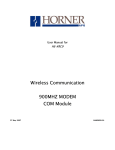
XBee-PRO® 900HP RS-232/RS-485/USB RF Modem Overview Interfacing Protocol Product Manual For XBee-PRO 900HP RF Modem Part Numbers: XM-M92-2P... XM-M92-4P... XM-M92-UP... 900 MHz Stand-alone RF Modems by Digi International Inc. Digi International World Headquarters 11001 Bren Road East Minnetonka, MN 55343 Phone: 952-912-3444 or 877-912-3444 Fax: 952-912-4952 90002200_A 2013.12.23 XBee‐PRO® 900HP RS‐232/RS‐485/USB RF Modem‐ Product Manual © 2013 Digi International Inc. All rights reserved No part of the contents of this manual may be transmitted or reproduced in any form or by any means without the written permission of Digi International Inc. XBee‐PRO® 900HP RF Modem is a trademark of Digi International Inc. Technical Support: Phone: (866) 765‐9885 toll‐free U.S.A. and Canada (801) 765‐9885 Worldwide 8:00 am ‐ 5:00 pm [U.S. Mountain Time] Online Support: http://www.digi.com/support/eservice/login.jsp Email: [email protected] © 2013 Digi International Inc. ii XBee‐PRO® 900HP RS‐232/RS‐485/USB RF Modem‐ Product Manual Contents 1. Overview of the 900HP RF Modem 4 Features of the 900HP RF Modem Worldwide Acceptance 4 5 Specifications of the 900HP RF Modem 5 External Interface of the 900HP RF Modem RF Modem Symbols 6 9 2. Interfacing Protocol 10 RS-232 Operation 10 RS-232 Pin Signals 10 RS-232 Wiring Diagram 11 RS-485 (2-wire) Operation RS-485 Pin Signals 12 13 RS-485 Wiring Diagram 13 RS-485 (4-wire) Operation and RS-422 Operation 14 RS-485 Pin Signals 15 RS-485 Wiring Diagrams 15 RS-485/422 Connection Guidelines USB Operation 16 17 USB Pin Signals 17 Appendix A: Agency Certifications 18 FCC (United States) Certification Labeling Requirements FCC Notices 18 18 18 Limited Modular Approval FCC-approved Antennas 18 19 IC (Industry Canada) Certification 19 Appendix B: Additional Information 23 © 2013 Digi International Inc. iii XBee‐PRO® 900HP RS‐232/RS‐485/USB RF Modem‐ Product Manual 1. Overview of the 900HP RF Modem The XBee-PRO 900HP RF Modem is a small, low-power solution that uses the XBeePRO 900HP 900 MHz RF Module in an enclosure to communicate with systems using RS-232, RS-485, and USB interfaces. It allows you to easily make your existing wired systems wireless simply by connecting to this product. When a system is connected to the XBee-PRO 900HP RF Modem, it can transmit and receive data from multiple radios on the same wireless network. This is achieved by using Digi’s XBee-PRO 900HP RF Module. This manual is not a comprehensive manual that provides a full description of the 900HP RF Modem. This manual only covers the interfaces needed to communicate with the 900HP 900 MHz RF Module. For an extensive guide on use of the 900HP 900 MHz RF Module, see the XBee-PRO 900 HP/XBee-PRO XSC RF Modules Product Manual. 1.1. Features of the 900HP RF Modem Long Range Data Integrity Range • Indoor/Urban: 200kbps: Up to 1000' (305 m), 10kbps: Up to 2000' (610m) • Outdoor line-of-sight: 200kbps: Up to 4 miles (6.5km), 10kbps: Up to 9 miles (15.5km) Low Power Receive current: 60 mA (@9V) Transmit current: 140 mA (@9V) Easy-to-Use No configuration required for out-of-the-box RF data communications. Transmit power: Up to 24 dBm (250 mW) (software selectable) Free X-CTU software (Testing and configuration software) Receiver sensitivity: -101 dBm (200kbps), -110 dBm (10kbps) RS-232 and RS-485 variants configurable via the mini USB port. RF data rate: 200kbps, 10kbps Advanced configurations available through standard AT and binary commands. Advanced Networking and Security True peer-to-peer (no “master” required) communications. Mesh, point-to-point and point-to-multipoint topologies supported. Retries and acknowledgements. 8 hopping channels, each with over 65,000 available network addresses. Built in RS-232/RS-485/USB interfacing. Small form factor. Software-selectable serial interface baud rates. Support for multiple data formats (parity, start and stop bits, etc.) Free and unlimited Technical Support. FHSS (Frequency Hopping Spread Spectrum). © 2013 Digi International Inc. 4 XBee‐PRO® 900HP RS‐232/RS‐485/USB RF Modem‐ Product Manual 1.1.1. Worldwide Acceptance FCC Approved (U.S.A) Refer to Appendix A for FCC Requirements. Systems that include XBee®/XBee-PRO® 900HP RF modems inherit Digi Certifications. ISM (Industrial, Scientific and Medical) 900 GHz frequency band Manufactured under ISO 9001:2000 registered standards XBee®/XBee-PRO® 900HP (900 MHz) RF Modems are approved for use in U.S, Canada, and Australia. 1.2. Specifications of the 900HP RF Modem Table 1‐01. Specifications of the XBee‐PRO 900HP RS‐232/RS‐485/USB RF Modem Specification XBee-PRO Performance Indoor/Urban Range 200kbps: Up to 1000 ft (305m) 10kbps: Up to 2000 ft (610m) Outdoor line-of-sight Range 200kbps: Up to 4 miles (6.5km) w/ 2.1 dB dipole antenna 10kbps: Up to 9 miles (15.5km) w/ 2.1dB dipole antenna Transmit power output Up to 24 dBm (250 mW) software selectable RF Data Rate (High) 200kbps RF Data Rate (Low) 10kbps Interface data rate 9600-230400kbps (Software selectable, includes non-standard baud rates) Receiver sensitivity -101 dBm (200kbps), -110 dBm (10kbps) Networking and Security Frequency 902-928MHz (located in the 900MHz ISM Band) Spread spectrum Frequency hopping Supported network topologies Mesh, point-to-point, point-to-multipoint, peer-to-peer Antenna Connector RPSMA (reverse polarity SMA) Impedance 50 ohms unbalanced Power Requirements Power supply 7-30 VDC Receive current 60 mA (@9V) Transmit current 140 mA (@9V) Physical Properties Size 4.500” x 2.750” x 1.125” (11.4cm x 7.0cm x 2.9cm) Weight 5.25 oz. (150 g) Data connection Female DB-9, RS-485/422 screw terminal, USB Type B, USB Mini-B Operating temperature -40 - 85º C (Industrial) Certifications (partial list) United States (FCC Part 15.247) MCQ-XB900HP Industry Canada (IC) 1846A-XB900HP Australia C-Tick RoHS Compliant * See Appendix A for region‐specific certification requirements. © 2013 Digi International Inc. 5 XBee‐PRO® 900HP RS‐232/RS‐485/USB RF Modem‐ Product Manual 1.3. External Interface of the 900HP RF Modem Figure 1‐01. Front View (RS‐232) 1-01a. RS-232 Serial Port Standard female DB-9 1-01b. RS-232 Power Connector 7-30 VDC power connector 1-01c. RS-232 Reset Button The reset button resets (re-boots) the XBee-PRO 900HP RF Modem. This button only applies when using the configuration tabs of Digi’s XCTU Software. Figure 1‐02. Back View (RS‐232) 1-02a. RS-232 RSSI LEDs RSSI LEDs indicate the amount of fade margin present in an active wireless link. Fade margin is defined as the difference between the incoming signal strength and the modem's receiver sensitivity. 3 LEDs ON = Very Strong Signal (> 30 dB fade margin) 2 LEDs ON = Strong Signal (>20 dB fade margin) 1 LED ON = Moderate Signal (>10 dB fade margin) 0 LED ON = Weak Signal (<10 dB fade margin) 1-02b. RS-232 I/O and Power LEDs LEDs indicate RF modem activity as follows: Yellow (top LED) = Serial Data Out (to host) Green (middle) = Serial Data In (from host) Red (bottom) = Power/TX Indicator (the red light is on when powered, off briefly during RF transmission) 1-02c. RS-232 Commissioning Push Button The commissioning push button provides a variety of simple functions to aid in deploying devices in a network. See “Commissioning Pushbutton” in chapter 7 of the XBee-PRO 900HP/XBee-PRO XSC RF Modules Product Manual for more detail. 1-02d. RS-232 USB Mini-B Port When the USB Mini-B is plugged in, all RS-232 communications to and from the XBee are disabled. The USB is to serve as a configuration port. The XBee should not transmit when the USB is plugged in. 1-02e. RS-232 Antenna Port The antenna port is a 50Ω RF signal connector for connecting to an external antenna. The connector type is RPSMA (Reverse Polarity SMA) female. The connector has threads on the outside of a barrel and a male center conductor. © 2013 Digi International Inc. 6 XBee‐PRO® 900HP RS‐232/RS‐485/USB RF Modem‐ Product Manual Figure 1‐03. Front View (RS‐485) 1-03a. RS-485 Serial Port Phoenix 6-pin connector. 1-03b. RS-485 Power Connector 7-30 VDC power connector. 1-03c. RS-485 DIP Switch 120 ohms termination for the receiving differential pairs if switch is in the up position. Switch 1 is for half duplex (2 wire) termination. Switch 2 is for full duplex (4 wire) termination. 1-03d. RS-485 Reset Button The reset button resets (re-boots) the XBee-PRO 900HP RF Modem. This button only applies when using the configuration tabs of Digi’s XCTU Software. Figure 1‐04. Back View (RS‐485) 1-04a. RS-485 RSSI LEDs RSSI LEDs indicate the amount of fade margin present in an active wireless link. Fade margin is defined as the difference between the incoming signal strength and the modem's receiver sensitivity. 3 LEDs ON = Very Strong Signal (> 30 dB fade margin) 2 LEDs ON = Strong Signal (>20 dB fade margin) 1 LED ON = Moderate Signal (>10 dB fade margin) 0 LED ON = Weak Signal (<10 dB fade margin) 1-04b. RS-485 I/O and Power LEDs LEDs indicate RF modem activity as follows: Yellow (top LED) = Serial Data Out (to host) Green (middle) = Serial Data In (from host) Red (bottom) = Power/TX Indicator (the red light is on when powered, off briefly during RF transmission) 1-04c. RS-485 Commissioning Push Button The commissioning push button provides a variety of simple functions to aid in deploying devices in a network. See “Commissioning Pushbutton” in chapter 7 of the XBee-PRO 900HP/XBee-PRO XSC RF Modules Product Manual for more detail. 1-04d. RS-485 USB Mini-B Port When the USB Mini-B is plugged in, all RS-485 communications to and from the XBee are disabled. The USB is to serve as a configuration port. The XBee should not transmit if USB is plugged in. 1-04e. RS-485 Antenna Port The antenna port is a 50Ω RF signal connector for connecting to an external antenna. The connector type is RPSMA (Reverse Polarity SMA) female. The connector has threads on the outside of a barrel and a male center conductor. © 2013 Digi International Inc. 7 XBee‐PRO® 900HP RS‐232/RS‐485/USB RF Modem‐ Product Manual Figure 1‐05. Front View (USB) 1-05a. USB Port Type B USB port. 1-05b. USB Power Connector 7-30 VDC power connector. 1-05c. USB Reset Button The reset button resets (re-boots) the XBee-PRO 900HP RF Modem. This button only applies when using the configuration tabs of Digi’s XCTU Software. Figure 1‐06. Back View (USB) 1-06a. USB RSSI LEDs RSSI LEDs indicate the amount of fade margin present in an active wireless link. Fade margin is defined as the difference between the incoming signal strength and the modem's receiver sensitivity. 3 LEDs ON = Very Strong Signal (> 30 dB fade margin) 2 LEDs ON = Strong Signal (>20 dB fade margin) 1 LED ON = Moderate Signal (>10 dB fade margin) 0 LED ON = Weak Signal (<10 dB fade margin) 1-06b. USB I/O and Power LEDs LEDs indicate RF modem activity as follows: Yellow (top LED) = Serial Data Out (to host) Green (middle) = Serial Data In (from host) Red (bottom) = Power/TX Indicator (the red light is on when powered, off briefly during RF transmission) 1-06c. USB Commissioning Push Button The commissioning push button provides a variety of simple functions to aid in deploying devices in a network. See “Commissioning Pushbutton” in chapter 7 of the XBee-PRO 900HP/XBee-PRO XSC RF Modules Product Manual for more detail. 1-06d. USB Antenna Port The antenna port is a 50Ω RF signal connector for connecting to an external antenna. The connector type is RPSMA (Reverse Polarity SMA) female. The connector has threads on the outside of a barrel and a male center conductor. © 2013 Digi International Inc. 8 XBee‐PRO® 900HP RS‐232/RS‐485/USB RF Modem‐ Product Manual 1.4. RF Modem Symbols The following symbols are found on top of the RF Modem. The description of the symbol is next to the symbol. © 2013 Digi International Inc. 9 XBee‐PRO® 900HP RS‐232/RS‐485/USB RF Modem‐ Product Manual 2. Interfacing Protocol The XBee-PRO 900HP RS-232/485/USB RF Modem supports the following interfacing protocols: • RS-232 • RS-485 (2-wire) half-duplex • RS-485 (4-wire) and RS-422 • USB 2.1. RS-232 Operation 2.1.1. RS-232 Pin Signals Figure 2‐01. Pins used on the female RS‐232 (DB‐9) Serial Connector Table 2‐01. RS‐232 Pin Assignments and Implementation DB-9 Pin RS-232 Name Description Implementation 1 DCD Data-Carrier-Detect Connected to DSR (pin 6) 2 RXD Received Data Serial data exiting the RF modem (from host) 3 TXD Transmitted Data Serial data entering into the RF modem (from host) 4 DTR Data-Terminal-Ready 2 – 0xFFFF [x 100 msec] 5 GND Ground Signal 0x20 – 0x7F 6 DSR Data-Set-Ready 0-4 Request-to-Send/Command Mode RTS (request-to-send) flow control: By default, this pin is not used. To configure this pin to regulate the flow of serial data exiting the modem, refer to the Serial Communications and RT command section CMD: Refer to Binary Commands and RT Command Sections to enable binary command programming 7 RTS / CMD 8 CTS Clear-to-Send CTS (clear-to-send) flow control –When pin is driven low, UART host is permitted to send serial data to the modem. Refer to the Serial Communications and CS Command sections for more information 9 RI Ring Indicator Optional power input (protection circuitry to prevent back flow from other power sources internal to the board) © 2013 Digi International Inc. 10 XBee‐PRO® 900HP RS‐232/RS‐485/USB RF Modem‐ Product Manual 2.1.2. RS-232 Wiring Diagram Figure 2‐02. RS‐232 Device DTE Device (male DB‐9 connector) wired to a DCE RF modem (female DB‐9) XBee‐PRO RF Modem DCE RF Modem to a DCE RS-232 Device Figure 2‐03. DCE RF Modem (female DB‐9 connector) wired to an RS‐232 DCE Device (male DB‐9) XBee‐ PRO RF Modem © 2013 Digi International Inc. 11 XBee‐PRO® 900HP RS‐232/RS‐485/USB RF Modem‐ Product Manual Sample Wireless Connection: DTE <--> DCE DCE <--> DCE Figure 2‐04. Typical wireless link between DTE and DCE devices 2.2. RS-485 (2-wire) Operation Note that with the RS-485 variant of the 900HP RF Modem, the RF Modem is defaulted with the D7 command (AT parameter) to 7. This parameter controls the TX enable signal and allows the modem to output any data in the DO buffer to the host device for the RS-485 interface. In the event that the parameter is accidentally changed, which would halt RS-485 communication, a USB mini cable should be plugged into the modem to reconfigure it. You can reconfigure by using Digi’s X-CTU. With the USB plugged in: 1. Open X-CTU and select the Com port of the USB. 2. Select the Terminal tab and type '+++'. The system will respond with 'OK'. 3. Type “ATD77” then <Enter>, and the system will respond with 'OK'. Type “ATWR” then <Enter>, and the system will respond with “OK”. 4. Type “ATCN” then <Enter> to exit command mode, and the system will respond with “OK”. 5. Unplug the USB and return to the existing RS-485 interface. The 900HP RF Modem is now ready to communicate in RS-485 model. © 2013 Digi International Inc. 12 XBee‐PRO® 900HP RS‐232/RS‐485/USB RF Modem‐ Product Manual NOTE: Failure to enter AT Command Mode is most commonly due to baud rate mismatch. Ensure the “Baud" setting on the “PC Settings” tab matches the BD (Interface Data Rate) setting of the RF modem (by default, BD parameter = 3, which is associated with 9600 baud). 2.2.1. RS-485 Pin Signals Figure 2‐05. Pins used on the RS‐485 (2 wire) Phoenix 6 Pin Connector Table 2‐02. Phoenix 6 Pin Pins used on the RS‐485 (2 wire) Phoenix 6 Pin Connector RS-485 Name Description Implementation 1 TX/RX+ Negative Data Line Transmit serial data to and from the RF modem 2 TX/RX- Positive Data Line Transmit serial to and from the RF modem 5 GND Ground Signal Ground Power Signal Optional power input (protection circuitry to prevent back flow from other power sources internal to the board). 6 PWR 3, 4 Not Used 2.2.2. RS-485 Wiring Diagram Figure 2‐06. RF Modem in an RS‐485 (2 wire) half duplex © 2013 Digi International Inc. 13 XBee‐PRO® 900HP RS‐232/RS‐485/USB RF Modem‐ Product Manual 2.3. RS-485 (4-wire) Operation and RS-422 Operation Note that with the RS-485 variant of the 900HP RF Modem, the RF Modem is defaulted with the D7 command (AT parameter) to 7. This parameter controls the TX enable signal and allows the modem to output any data in the DO buffer to the host device for the RS-485/422 interface. In the event that the parameter is accidentally changed, which would halt RS-485 communication, a USB mini cable should be plugged into the modem to reconfigure it. You can reconfigure by using Digi's X-CTU. With the USB plugged in: 1. Open X-CTU and select the Com port of the USB. 2. Select the Terminal tab and type “+++”. The system will respond with “OK”. 3. Type “ATD77” then <Enter>, and the system will respond with “OK”. 4. Type “ATWR” then <Enter>, and the system will respond with “OK”. 5. Type “ATCN” then <Enter> to exit command mode, and the system will respond with “OK”. 6. Unplug the USB and return to the existing RS-485/422 interface. The 900HP RF Modem is now ready to communicate in RS-485 mode. NOTE: Failure to enter AT Command Mode is most commonly due to baud rate mismatch. Ensure the 'Baud' setting on the “PC Settings” tab matches the BD (Interface Data Rate) setting of the RF modem (by default, BD parameter = 3, which is associated with 9600 baud). © 2013 Digi International Inc. 14 XBee‐PRO® 900HP RS‐232/RS‐485/USB RF Modem‐ Product Manual 2.3.1. RS-485 Pin Signals Figure 2‐07. Pins used on the RS‐485 (4‐wire) Phoenix 6 Pin Connector Table 2‐03. RS‐485 (4‐wire) 6‐pin Connector Pin Assignments and Implementation Phoenix 6 Pin RS-485 Name Description Implementation 1 TX+ Transmit Positive Serial data sent from RF modem 2 TX- Transmit Negative Data Line Serial data received by the RF modem 5 RX+ Receive Positive Data Line Serial data received the RF modem 4 RX- Receive Negative Data Line Serial data received by the RF modem 5 GND Ground Signal Ground Power Signal Optional power input (protection circuitry to prevent back flow from other power sources internal to the board) 6 PWR 2.3.2. RS-485 Wiring Diagrams Figure 2‐08. RF Modem in an RS‐485 (4‐wire) environment © 2013 Digi International Inc. 15 XBee‐PRO® 900HP RS‐232/RS‐485/USB RF Modem‐ Product Manual Figure 2‐09. RF Modem in an RS‐422 environment 2.3.3. RS-485/422 Connection Guidelines The RS-485/422 protocol provides a solution for wired communications that can tolerate high noise and push signals over long cable lengths. RS-485/422 signals can communicate as far as 4000 feet (1200 m). RS-232 signals are suitable for cable distances up to 100 feet (30.5 m). RS-485 offers multi-drop capability in which up to 32 nodes can be connected. The RS-422 protocol is used for point-to-point communications. Suggestions for integrating the 900HP RF Modem with the RS-485/422 protocol: Twisted pair cabling is used for the positive and negative data lines. An Ethernet cable is good for twisted pairs. When using Ethernet twisted pair cabling: Select wires so that TX+ and TX-are connected to a twisted pair. Likewise, select wires so that RX+ and RX- are connected to a twisted pair. (For example, tie the green and white/green wires to TX+ and TX-). This reduces the amount of noise on the data line. © 2013 Digi International Inc. 16 XBee‐PRO® 900HP RS‐232/RS‐485/USB RF Modem‐ Product Manual 2.4. USB Operation Note that when a Mini-USB cable is plugged into the 900HP RF Modem, communication to and from the RS-232 interface and the RS-485/422 is halted. USB communications take precedence over all other interfaces when you plug it in. To restore communication with other interfaces, the USB cable should be unplugged. **The Mini-B USB Connector is intended as a configuration port. The RF Modem should not transmit data when the Mini USB cable is connected. 2.4.1. USB Pin Signals Figure 2‐010.Pins used on the Type B USB Connector Table 2‐04. Type B USB Connector Pin Assignments and Implementation Phoenix 6 Pin Name Description Implementation 1 VBUS Power Power the RF modem 2 D- Negative Data Line Transmit data to and from the RF modem 5 D+ Positive Data Line Transmit data to and from the RF modem 4 GND Ground Signal Ground Figure 2‐011. Pins used on the Mini‐B USB Connector Table 2‐05. Mini‐B USB Connector Pin Assignments and Implementation Pin Name Description Implementation 1 VBUS Power Power the RF modem 2 D- Negative Data Line Transmit data to and from the RF modem 5 D+ Positive Data Line Transmit data to and from the RF modem 4 ID Permits distinction of host connection from slave connection Not connected 5 GND Ground Signal Ground © 2013 Digi International Inc. 17 XBee‐PRO® 900HP RS‐232/RS‐485/USB RF Modem‐ Product Manual Appendix A: Agency Certifications FCC (United States) Certification The XBee-PRO® 900HP RF Modem complies with Part 15 of the FCC rules and regulations. Compliance with the labeling requirements, FCC notices and antenna usage guidelines is required. RF Modems/integrators must comply with the following regulations: 1. The system integrator must ensure that the text provided with this device [Figure A-01] is placed on the outside of the final product and within the final product operation manual. 2. The XBee-PRO® 900HP RF Modem may only be used with antennas that have been tested and approved for use with this modem (refer to Table A-01). Labeling Requirements WARNING: The Original Equipment Manufacturer (OEM) must ensure that FCC labeling requirements are met. This includes a clearly visible label on the outside of the final product enclosure that displays the text shown in the figure below. Figure A‐01. Required FCC Label for OEM products containing the XBee‐PRO® 900HP RF Modem. Contains FCC ID: MCQ-XB900HP The enclosed device complies with Part 15 of the FCC Rules. Operation is subject to the following two conditions: (i.) this device may not cause harmful interference and (ii.) this device must accept any interference received, including interference that may cause undesired operation. FCC Notices IMPORTANT: The XBee-PRO® 900HP RS-232/RS-485/USB RF Module has been certified by the FCC for use with other products without any further certification (as per FCC section 2.1091). Modifications not expressly approved by Digi could void the user's authority to operate the equipment. IMPORTANT: OEMs must test final product to comply with unintentional radiators (FCC section 15.107 and 15.109) before declaring compliance of their final product to Part 15 of the FCC Rules. IMPORTANT: The RF Module has been certified for remote and base radio applications. If the module will be used for portable applications, the device must undergo SAR testing. This equipment has been tested and found to comply with the limits for a Class B digital device, pursuant to Part 15 of the FCC Rules. These limits are designed to provide reasonable protection against harmful interference in a residential installation. This equipment generates, uses and can radiate radio frequency energy and, if not installed and used in accordance with the instructions, may cause harmful interference to radio communications. However, there is no guarantee that interference will not occur in a particular installation. If this equipment does cause harmful interference to radio or television reception, which can be determined by turning the equipment off and on, the user is encouraged to try to correct the interference by one or more of the following measures: Re-orient or relocate the receiving antenna, Increase the separation between the equipment and receiver, Connect equipment and receiver to outlets on different circuits, or Consult the dealer or an experienced radio/TV technician for help. Limited Modular Approval This modem contains an RF module approved for Limited Modular use operating as a mobile transmitting device with respect to section 2.1091 and is limited to OEM installation for Mobile and © 2013 Digi International Inc. 18 XBee‐PRO® 900HP RS‐232/RS‐485/USB RF Modem‐ Product Manual Fixed applications only. During final installation, end-users are prohibited from access to any programming parameters. Professional installation adjustment is required for setting module power and antenna gain to meet EIRP compliance for high gain antenna(s). Final antenna installation and operating configurations of this transmitter including antenna gain and cable loss must not exceed the EIRP of the configuration used for calculating MPE. Grantee (Digi) must coordinate with OEM integrators to ensure the end-users and installers of products operating with the modem are provided with operating instructions to satisfy RF exposure requirements. The FCC grant is valid only when the device is sold to OEM integrators. Integrators are instructed to ensure the end-user has no manual instructions to remove, adjust or install the device. FCC-approved Antennas WARNING: This device has been tested with Reverse Polarity SMA connectors with the antennas listed in the tables of this section. When integrated into OEM products, fixed antennas require installation preventing end-users from replacing them with nonapproved antennas. Antennas not listed in the tables must be tested to comply with FCC Section 15.203 (unique antenna connectors) and Section 15.247 (emissions). Fixed Base Station and Mobile Applications Digi RF modules are pre-FCC approved for use in fixed base station and mobile applications. When the antenna is mounted at least 20cm (8") from nearby persons, the application is considered a mobile application. Portable Applications and SAR Testing If the module will be used at distances closer than 20cm to all persons, the device may be required to undergo SAR testing. Co-location with other transmitting antennas closer than 20cm should be avoided. RF Exposure This statement must be included as a CAUTION statement in OEM product manuals. WARNING: This equipment is approved only for mobile and base station transmitting devices. Antenna(s) used for this transmitter must be installed to provide a separation distance of at least 20 cm from all persons and must not be co-located or operating in conjunction with any other antenna or transmitter. IC (Industry Canada) Certification This device complies with Industry Canada licence-exempt RSS standard(s). Operation is subject to the following two conditions: (1) this device may not cause interference, and (2) this device must accept any interference, including interference that may cause undesired operation of the device. Le présent appareil est conforme aux CNR d'Industrie Canada applicables aux appareils radio exempts de licence. L'exploitation est autorisée aux deux conditions suivantes: (1) l'appareil ne doit pas produire de brouillage, et (2) l'utilisateur de l'appareil doit accepter tout brouillage radioélectrique subi, même si le brouillage est susceptible d'en compromettre le fonctionnement Labeling Requirements Labeling requirements for Industry Canada are similar to those of the FCC. A clearly visible label on the outside of the final product enclosure must display one of the following text: Contains IC: 1846A-XB900HP The integrator is responsible for its product to comply with IC ICES-003 and FCC Part 15, Sub. BUnintentional Radiators. ICES-003 is the same as FCC Part 15 Sub. B and Industry Canada accepts FCC test report or CISPR 22 test report for compliance with ICES-003. © 2013 Digi International Inc. 19 XBee‐PRO® 900HP RS‐232/RS‐485/USB RF Modem‐ Product Manual Antenna Options: 900 MHz Antenna Listings The antennas in the tables below have been approved for use with this product. Digi does not carry all of these antenna variants. Contact Digi Sales for available antennas. Table A-01. Antennas approved for use with the XBee-PRO 900HP RF Modem Part Number Gain Application Cable Loss or Power Reduction for S3B Radio Type Connector A09-F0 Fiberglass Base RPN 0 dBi Fixed 0dB A09-F1 Fiberglass Base RPN 1.0 dBi Fixed 0dB A09-F2 Fiberglass Base RPN 2.1 dBi Fixed 0dB A09-F3 Fiberglass Base RPN 3.1 dBi Fixed 0dB A09-F4 Fiberglass Base RPN 4.1 dBi Fixed 0dB A09-F5 Fiberglass Base RPN 5.1 dBi Fixed 0dB A09-F6 Fiberglass Base RPN 6.1 dBi Fixed 0dB A09-F7 Fiberglass Base RPN 7.1 dBi Fixed 0dB A09-F8 Fiberglass Base RPN 8.1 dBi Fixed 0dB Omni-directional antennas A09-F9 Base Station RPSMAF 9.2dBi Fixed 0dB A09-W7 Wire Base Station RPN 7.1 dBi Fixed 0dB A09-F0 Fiberglass Base RPSMA 0 dBi Fixed 0dB A09-F1 Fiberglass Base RPSMA 1.0 dBi Fixed 0dB A09-F2 Fiberglass Base RPSMA 2.1 dBi Fixed 0dB A09-F3 Fiberglass Base RPSMA 3.1 dBi Fixed 0dB A09-F4 Fiberglass Base RPSMA 4.1 dBi Fixed 0dB A09-F5 Fiberglass Base RPSMA 5.1 dBi Fixed 0dB A09-F6 Fiberglass Base RPSMA 6.1 dBi Fixed 0dB A09-F7 Fiberglass Base RPSMA 7.1 dBi Fixed 0dB A09-F8 Fiberglass Base RPSMA 8.1 dBi Fixed 0dB A09-M7 Base Station RPSMAF 7.2dBi Fixed 0dB A09-W7SM Wire Base Station RPSMA 7.1 dBi Fixed 0dB A09-F0TM Fiberglass Base RPTNC 0 dBi Fixed 0dB A09-F1TM Fiberglass Base RPTNC 1.0 dBi Fixed 0dB A09-F2TM Fiberglass Base RPTNC 2.1 dBi Fixed 0dB A09-F3TM Fiberglass Base RPTNC 3.1 dBi Fixed 0dB A09-F4TM Fiberglass Base RPTNC 4.1 dBi Fixed 0dB A09-F5TM Fiberglass Base RPTNC 5.1 dBi Fixed 0dB A09-F6TM Fiberglass Base RPTNC 6.1 dBi Fixed 0dB A09-F7TM Fiberglass Base RPTNC 7.1 dBi Fixed 0dB A09-F8TM Fiberglass Base RPTNC 8.1 dBi Fixed 0dB A09-W7TM Wire Base Station RPTNC 7.1 dBi Fixed 0dB A09-HSM-7 Straight half-wave RPSMA 3.0 dBi Fixed / Mobile 0dB A09-HASM-675 Articulated half- RPSMA 2.1 dBi Fixed / Mobile 0dB A09-HABMM-P6I Articulated half- MMCX 2.1 dBi Fixed / Mobile 0dB A09-HABMM-6-P6I Articulated half- MMCX 2.1 dBi Fixed / Mobile 0dB A09-HBMM-P6I Straight half-wave MMCX 2.1 dBi Fixed / Mobile 0dB A09-HRSM Right angle half- RPSMA 2.1 dBi Fixed 0dB A09-HASM-7 Articulated half- RPSMA 2.1 dBi Fixed 0dB © 2013 Digi International Inc. 20 XBee‐PRO® 900HP RS‐232/RS‐485/USB RF Modem‐ Product Manual A09-HG Glass mounted RPSMA 2.1 dBi Fixed 0dB A09-HATM Articulated half- RPTNC 2.1 dBi Fixed 0dB A09-H Half-wave dipole RPSMA 2.1 dBi Fixed 0dB A09-HBMMP6I A09-QBMMP6I MMCX MMCX 2.1dBi 1.9 dBi Mobile Mobile 0dB 0dB Integrated 1.9 dBi Mobile 0dB 29000187 1/2 wave antenna 1/4 wave antenna 1/4 wave integrated wire antenna Helical Integrated -2.0 dBi Fixed/Mobile 0dB A09-QW Quarter-wave wire Permanent 1.9 dBi Fixed / Mobile 0dB A09-QRAMM 3 “Quarter-wave MMCX 2.1 dBi Fixed / Mobile 0dB A09-QI A09-QSM-3 Quarter-wave RPSMA 1.9 dBi Fixed / Mobile 0dB A09-QSM-3H Heavy duty quarter- RPSMA 1.9 dBi Fixed / Mobile 0dB A09-QBMM-P6I Quarter-wave w/ 6” MMCX 1.9 dBi Fixed / Mobile 0dB A09-QHRN Miniature Helical Permanent -1 dBi Fixed / Mobile 0dB A09-QHSN Miniature Helical Permanent -1 dBi Fixed / Mobile 0dB A09-QHSM-2 2” Straight RPSMA 1.9 dBi Fixed / Mobile 0dB A09-QHRSM-2 2" Right angle RPSMA 1.9 dBi Fixed / Mobile 0dB A09-QHRSM-170 1.7" Right angle RPSMA 1.9 dBi Fixed / Mobile 0dB A09-QRSM-380 3.8" Right angle RPSMA 1.9 dBi Fixed / Mobile 0dB A09-QAPM-520 5.2” Articulated Permanent 1.9 dBi Fixed / Mobile 0dB A09-QSPM-3 3” Straight screw Permanent 1.9 dBi Fixed / Mobile 0dB A09-QAPM-3 3” Articulated screw Permanent 1.9 dBi Fixed / Mobile 0dB A09-QAPM-3H 3” Articulated screw Permanent 1.9 dBi Fixed / Mobile 0dB A09-DPSM-P12F omni directional RPSMA 3.0 dBi Fixed 0dB A09-D3NF-P12F omni directional RPN 3.0 dBi Fixed 0dB A09-D3SM-P12F omni directional w/ RPSMA 3.0 dBi Fixed 0dB A09-D3PNF omni directional RPN 3.0 dBi Fixed 0dB A09-D3TM-P12F omni directional w/ RPTNC 3.0 dBi Fixed 0dB A09-D3PTM omni directional RPTNC 3.0 dBi Fixed 0dB A09-M0SM Mag Mount RPSMA 0 dBi Fixed 0dB A09-M2SM Mag Mount RPSMA 2.1 dBi Fixed 0dB A09-M3SM Mag Mount RPSMA 3.1 dBi Fixed 0dB A09-M5SM Mag Mount RPSMA 5.1 dBi Fixed 0dB A09-M7SM Mag Mount RPSMA 7.1 dBi Fixed 0dB A09-M8SM Mag Mount RPSMA 8.1 dBi Fixed 0dB A09-M0TM Mag Mount RPTNC 0 dBi Fixed 0dB A09-M2TM Mag Mount RPTNC 2.1 dBi Fixed 0dB A09-M3TM Mag Mount RPTNC 3.1 dBi Fixed 0dB A09-M5TM Mag Mount RPTNC 5.1 dBi Fixed 0dB A09-M7TM Mag Mount RPTNC 7.1 dBi Fixed 0dB A09-M8TM Mag Mount RPTNC 8.1 dBi Fixed 0dB A09-Y6 2 Element Yagi RPN 6.1 dBi Fixed / Mobile 0dB A09-Y7 3 Element Yagi RPN 7.1 dBi Fixed / Mobile 0dB A09-Y8 4 Element Yagi RPN 8.1 dBi Fixed / Mobile 0dB Yagi antennas A09-Y9 4 Element Yagi RPN 9.1 dBi Fixed / Mobile 0dB A09-Y10 5 Element Yagi RPN 10.1 dBi Fixed / Mobile 0dB A09-Y11 6 Element Yagi RPN 11.1 dBi Fixed / Mobile 0dB © 2013 Digi International Inc. 21 XBee‐PRO® 900HP RS‐232/RS‐485/USB RF Modem‐ Product Manual A09-Y12 7 Element Yagi RPN 12.1 dBi Fixed / Mobile 0dB A09-Y13 9 Element Yagi RPN 13.1 dBi Fixed / Mobile 0.8dB A09-Y14 10 Element Yagi RPN 14.1 dBi Fixed / Mobile 1.8dB A09-Y14 12 Element Yagi RPN 14.1 dBi Fixed / Mobile 1.8dB A09-Y15 13 Element Yagi RPN 15.1 dBi Fixed / Mobile 2.8dB A09-Y15 15 Element Yagi RPN 15.1 dBi Fixed / Mobile 2.8dB A09-Y6TM 2 Element Yagi RPTNC 6.1 dBi Fixed / Mobile 0dB A09-Y7TM 3 Element Yagi RPTNC 7.1 dBi Fixed / Mobile 0dB A09-Y8TM 4 Element Yagi RPTNC 8.1 dBi Fixed / Mobile 0dB A09-Y9TM 4 Element Yagi RPTNC 9.1 dBi Fixed / Mobile 0dB A09-Y10TM 5 Element Yagi RPTNC 10.1 dBi Fixed / Mobile 0dB A09-Y11TM 6 Element Yagi RPTNC 11.1 dBi Fixed / Mobile 0dB A09-Y12TM 7 Element Yagi RPTNC 12.1 dBi Fixed / Mobile 0dB A09-Y13TM 9 Element Yagi RPTNC 13.1 dBi Fixed / Mobile 0.8dB A09-Y14TM 10 Element Yagi RPTNC 14.1 dBi Fixed / Mobile 1.8dB A09-Y14TM 12 Element Yagi RPTNC 14.1 dBi Fixed / Mobile 1.8dB A09-Y15TM 13 Element Yagi RPTNC 15.1 dBi Fixed / Mobile 2.8dB A09-Y15TM 15 Element Yagi RPTNC 15.1 dBi Fixed / Mobile 2.8dB Transmitters with Detachable Antennas This radio transmitter (IC: 1846A-XB900HP) has been approved by Industry Canada to operate with the antenna types listed in the table above with the maximum permissible gain and required antenna impedance for each antenna type indicated. Antenna types not included in this list, having a gain greater than the maximum gain indicated for that type, are strictly prohibited for use with this device. Le présent émetteur radio (IC: 1846A-XB900HP) a été approuvé par Industrie Canada pour fonctionner avec les types d'antenne énumérés ci?dessous et ayant un gain admissible maximal et l'impédance requise pour chaque type d'antenne. Les types d'antenne non inclus dans cette liste, ou dont le gain est supérieur au gain maximal indiqué, sont strictement interdits pour l'exploitation de l'émetteur. Detachable Antenna Under Industry Canada regulations, this radio transmitter may only operate using an antenna of a type and maximum (or lesser) gain approved for the transmitter by Industry Canada. To reduce potential radio interference to other users, the antenna type and its gain should be so chosen that the equivalent isotropically radiated power (e.i.r.p.) is not more than that necessary for successful communication. Conformément à la réglementation d'Industrie Canada, le présent émetteur radio peut fonctionner avec une antenne d'un type et d'un gain maximal (ou inférieur) approuvé pour l'émetteur par Industrie Canada. Dans le but de réduire les risques de brouillage radioélectrique à l'intention des autres utilisateurs, il faut choisir le type d'antenne et son gain de sorte que la puissance isotrope rayonnée équivalente (p.i.r.e.) ne dépasse pas l'intensité nécessaire àl'établissement d'une communication satisfaisante. © 2013 Digi International Inc. 22 XBee‐PRO® 900HP RS‐232/RS‐485/USB RF Modem‐ Product Manual Appendix B: Additional Information 5-Year Warranty XBee RF Modems from Digi International, Inc. (the “Product”) are warranted against defects in materials and workmanship under normal use, for a period of 5-years from the date of purchase. In the event of a product failure due to materials or workmanship, Digi will repair or replace the defective product. For warranty service, return the defective product to Digi International, shipping prepaid, for prompt repair or replacement. The foregoing sets forth the full extent of Digi International's warranties regarding the Product. Repair or replacement at Digi International's option is the exclusive remedy. THIS WARRANTY IS GIVEN IN LIEU OF ALL OTHER WARRANTIES, EXPRESS OR IMPLIED, AND DIGI SPECIFICALLY DISCLAIMS ALL WARRANTIES OF MERCHANTABILITY OR FITNESS FOR A PARTICULAR PURPOSE. IN NO EVENT SHALL DIGI, ITS SUPPLIERS OR LICENSORS BE LIABLE FOR DAMAGES IN EXCESS OF THE PURCHASE PRICE OF THE PRODUCT, FOR ANY LOSS OF USE, LOSS OF TIME, INCONVENIENCE, COMMERCIAL LOSS, LOST PROFITS OR SAVINGS, OR OTHER INCIDENTAL, SPECIAL OR CONSEQUENTIAL DAMAGES ARISING OUT OF THE USE OR INABILITY TO USE THE PRODUCT, TO THE FULL EXTENT SUCH MAY BE DISCLAIMED BY LAW. SOME STATES DO NOT ALLOW THE EXCLUSION OR LIMITATION OF INCIDENTAL OR CONSEQUENTIAL DAMAGES. THEREFORE, THE FOREGOING EXCLUSIONS MAY NOT APPLY IN ALL CASES. This warranty provides specific legal rights. Other rights which vary from state to state may also apply. Contact Digi International Free and unlimited technical support is included with every Digi Radio Modem sold. For the best in wireless data solutions and support, please use the following resources: Documentation: http://www.digi.com/support/ Technical Support: Phone. 952-912-3444 U.S.A. and Canada 877-912-3444 Worldwide © 2013 Digi International Inc. Live Chat. http://www.digi.com/contactus/ E-Mail. http://www.digi.com/support/eservice/eservicelogin.jsp 23