1
Active antennas
Many GNSS receivers use active antennas,
which include an LNA. The LNA typically
provides pre-amplification gain of 20 to
30 dB, and has a low noise figure, which
determines the main contribution to the
cascaded noise figure for the receiver.
It is important that the LNA is as close
to the antenna as possible, which is why
it is incorporated in the same housing.
The antenna and LNA are normally
connected to the receiver unit by a coax
cable. In order to operate the LNA, DC
power is required, which is normally fed
through the same coax to save having
a second cable. When a receiver is
connected to the output of a simulator, the
antenna is removed.
The DC voltage on the coax centre
conductor is still present, but is not
a problem because the RF output of the
simulator is DC protected.
However, by removing the antenna you
are also removing the gain of the LNA
and this needs to be compensated for.
Compensation can be made using the
simulator’s signal control, but this may
impact the simulator’s dynamic range.
The best solution is to use an LNA with
the same noise figure and gain as the one
in the removed antenna, on the output of
the simulator. This way the simulator can
remain operating in the centre of its power
control range, and the receiver will have
the correct signal level at its input.
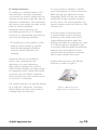
Figure 3 shows an LNA connected in the
RF signal path.
Figure 3: Simulator RF output fed through LNA to receiver
Devices with optional external antenna
connections
Some devices (such as PDAs and pocket
PCs) have, as well as a built-in antenna,
a 50 ohm miniature RF connector which
allows an external active antenna to be
connected. Very often, the device is able
to detect when the external antenna is
connected, because it detects a resistance
to ground of a few kilo-ohms. This enables
the power supply for the external antenna
(which is otherwise disabled, mainly to
conserve battery power), and switches
the RF input from the internal antenna
to the external one. In normal operation
this is fine, but if the external antenna
SPIRENT Application Note
connection is being used to input signals
from a simulator, a problem can occur.
If the simulator RF output is DC isolated
(as most are), the device under test will
not detect a DC resistance to ground, and
will not switch its RF input to the external
connection, preventing the simulator’s
signals reaching the device under test’s
RF front end. The solution to this problem
is to introduce a DC resistance to ground
into the connection between the simulator
and the device under test. This can be
done with a simple ‘current sink’ circuit,
comprising of a couple of components on
a small piece of 50 ohm microstrip circuit
board. Figure 4 shows this circuit.
Page
8