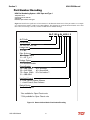
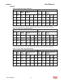
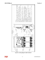
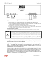
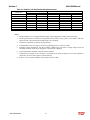
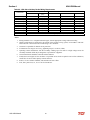
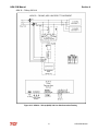
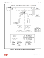
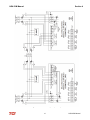
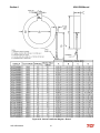
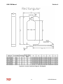
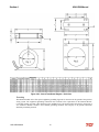
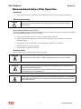
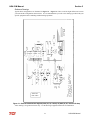
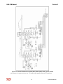
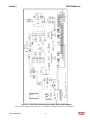
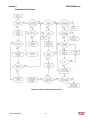
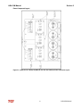
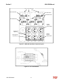
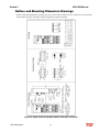
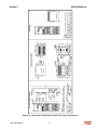
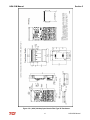
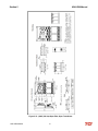
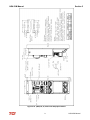
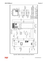
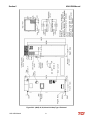
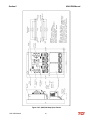
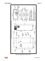
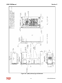
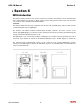
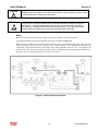
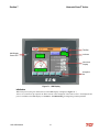
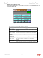
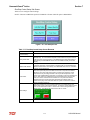
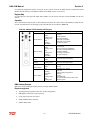
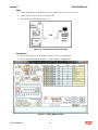
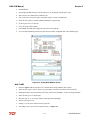
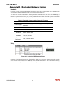
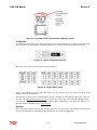
1
HarmonicGuard® Series Bus-Applied Active Harmonic Filter Installation, Operation, and Maintenance Manual TCI, LLC W132 N10611 Grant Drive Germantown, Wisconsin 53022 Phone: 414-357-4480 Fax: 414-357-4484 Helpline: 800-TCI-8282 Web Site: http://www.transcoil.com © 2014 TCI, LLC All rights reserved No part of this publication may be reproduced, stored in a retrieval system, or transmitted in any form or by any means, mechanical, electronic, photocopying, recording, or otherwise, without the prior written permission of TCI, LLC. The information in this manual is subject to change without notice. Every precaution has been taken in the preparation of this manual. TCI, LLC assumes no responsibility for errors or omissions. Neither is any liability assumed for damages resulting from the use of the information contained in this publication Table of Contents ■ Section 1 ....................................................................................................................... 1 HGA Quick Start Unit Software Setup for HMI Revision I ..................................................................................... 1 Section 2 .......................................................................................................................... 8 Safety Instructions ........................................................................................................................................................ 8 Overview .............................................................................................................................................................. 8 Warnings and Cautions ........................................................................................................................................ 8 Warnings .............................................................................................................................................................. 8 Cautions................................................................................................................................................................ 8 General Safety Instructions .................................................................................................................................. 9 General Terminology .................................................................................................................................................. 10 ■ Section 3 ..................................................................................................................... 11 Introduction ................................................................................................................................................................. 11 Intended Audience.............................................................................................................................................. 11 Additional Information ....................................................................................................................................... 11 Installation Checklist .......................................................................................................................................... 11 Receiving Inspection and Storage .............................................................................................................................. 12 Receiving Inspection .......................................................................................................................................... 12 TCI Limited Warranty Policy ............................................................................................................................. 12 Storage Instructions ............................................................................................................................................ 12 Product Description .................................................................................................................................................... 13 Filter Configuration ............................................................................................................................................ 14 Nameplate Data .................................................................................................................................................. 15 Part Number Encoding............................................................................................................................................... 16 HGA Part Numbering System – 480V Open and Type 1 ................................................................................... 16 HGA Part Numbering System – 480V Type 12 & 3R ....................................................................................... 17 HGA Part Numbering System – 600V ............................................................................................................... 18 HGA Part Numbering System – 480V Open & Type 1 (50° C)......................................................................... 19 3.4.5 Communications Part Numbering .......................................................................................................... 20 3.4.6 Pedestal Part Numbering........................................................................................................................ 20 Standard Product Ratings and Dimension Tables ................................................................................................... 21 3.5.1 480V 40°C ............................................................................................................................................. 21 3.5.2 600V 40°C ............................................................................................................................................. 22 480V 50°C.......................................................................................................................................................... 23 ■ Section 4 ..................................................................................................................... 24 Pre-installation Planning ............................................................................................................................................ 24 Verify the Application ........................................................................................................................................ 24 Select a Suitable Location .................................................................................................................................. 24 Working Space ................................................................................................................................................... 24 Mounting an Open Chassis Unit......................................................................................................................... 24 Cooling Diagrams .............................................................................................................................................. 24 Installation Guidelines ................................................................................................................................................ 29 Mounting ............................................................................................................................................................ 29 Wiring ............................................................................................................................................................... 29 Current Transformer Installation ........................................................................................................................ 31 Current Transformer Placement ......................................................................................................................... 32 HarmonicGuard Active Filter Operation ................................................................................................................. 51 Adjustments........................................................................................................................................................ 51 Start Up (Commissioning).................................................................................................................................. 51 General Operation .............................................................................................................................................. 51 ■ Section 5 ..................................................................................................................... 52 Maintenance and Service............................................................................................................................................ 52 HGA Reliability and Service Life ...................................................................................................................... 52 Periodic Maintenance ......................................................................................................................................... 52 Troubleshooting ................................................................................................................................................. 58 Troubleshooting Flow charts .............................................................................................................................. 60 Power Component Layout .................................................................................................................................. 61 Replacement Parts .............................................................................................................................................. 63 Factory Contacts and Technical Support ............................................................................................................ 63 Outline and Mounting Dimension Drawings ............................................................................................................ 64 ■ Section 6 ..................................................................................................................... 86 HMI Introduction ....................................................................................................................................................... 86 Installation Guidelines ................................................................................................................................................ 88 Checklist ............................................................................................................................................................. 88 Location.............................................................................................................................................................. 88 Mounting ............................................................................................................................................................ 88 Wiring 89 ■ Section 7 ..................................................................................................................... 93 Operation ..................................................................................................................................................................... 93 HMI Screen Elements ........................................................................................................................................ 93 Initialization ....................................................................................................................................................... 94 HMI Screens....................................................................................................................................................... 95 ■ Section 8 ................................................................................................................... 119 Maintenance .............................................................................................................................................................. 119 Clock Battery Replacement .............................................................................................................................. 119 Software Field Upgrades .................................................................................................................................. 119 Troubleshooting ........................................................................................................................................................ 120 HarmonicGuard Active Filter Fault.................................................................................................................. 120 Interface Module Problem ................................................................................................................................ 120 Fault Troubleshooting Notes ............................................................................................................................ 121 Fault Troubleshooting Flow Chart ................................................................................................................... 121 ■ Section 9 ................................................................................................................... 122 Appendix A – Installation Diagram......................................................................................................................... 122 Appendix B – Ethernet/IP Gateway and Modbus TCP/IP Option ....................................................................... 123 Introduction ...................................................................................................................................................... 123 Wiring ............................................................................................................................................................. 123 Configuration ................................................................................................................................................... 124 Register Map .................................................................................................................................................... 125 Operation .......................................................................................................................................................... 125 HMS Gateway to PLC Master Example........................................................................................................... 126 Required equipment ......................................................................................................................................... 126 Setup ............................................................................................................................................................. 126 Programming .................................................................................................................................................... 126 Appendix C – Modbus TCP/IP Gateway Option ................................................................................................... 129 Introduction ...................................................................................................................................................... 129 Wiring ............................................................................................................................................................. 129 Configuration ................................................................................................................................................... 130 Register Map .................................................................................................................................................... 131 Operation .......................................................................................................................................................... 131 HMS Gateway Example ................................................................................................................................... 131 Required equipment ......................................................................................................................................... 131 Setup ............................................................................................................................................................. 132 Programming .................................................................................................................................................... 132 Write To HMI................................................................................................................................................... 133 Appendix D – DeviceNet Gateway Option .............................................................................................................. 134 Introduction ...................................................................................................................................................... 134 Wiring ............................................................................................................................................................. 134 Configuration ................................................................................................................................................... 135 Operation .......................................................................................................................................................... 135 Establishing Correct Network Settings ............................................................................................................ 137 RSLinx Classics Settings: ................................................................................................................................ 137 RSNetworx: ...................................................................................................................................................... 138 RSLogix: .......................................................................................................................................................... 139 Appendix E – HGA Quick Start Unit Software Setup for HMI Revisions H and Earlier .................................. 141 Revision Description Date A Release 10/29/13 B -- 03/03/14 C Added 300A Added 150A 480V Added 150A 600V Updated Quick Start Guide Rev. B 09/10/14 D Updated 300A Drawings 09/26/14 E Added Floor Stand Added 600V 220A Added Legacy QS Guide as Appx. E Updated Watts Loss on Standard Product Ratings and Dimension Tables 11/5/14 HarmonicGuard® Active Section 1 1 ■ Section 1 1.1 HGA Quick Start Unit Software Setup for HMI Revision I Warning ! Be sure to read, understand, and follow all safety instructions. Warning ! Only qualified electricians should carry out all electrical installation and maintenance work on the HarmonicGuard Active (HGA) filter. Warning ! All wiring must be in accordance with the National Electrical Code (NEC) and/or any other codes that apply to the installation site. Warning Disconnect all power before working on the equipment. Do not attempt any work on a powered HGA filter. Warning The HGA filter, drive, motor, and other connected equipment must be properly grounded. Warning Warning HGA IOM Manual The HGA filter may receive power from two or more sources. Three-phase power is connected to the main input terminals of the HGA filter. All of these sources of power must be disconnected before working on the HGA filter. After switching off the power, always allow 5 minutes for the capacitors in the HGA filter and in the drive to discharge before working on the HGA filter, the drive, the motor, or the connecting wiring. It is good practice to check with a voltmeter to make sure that all sources of power have been disconnected and that all capacitors have discharged before beginning work. 1 HarmonicGuard® Active Section 1 1) Verify unit external connections Phase A, B, C power connection, with positive A-B-C phase rotation expected CT H1 Terminal is pointing toward the source CT feedback on phases A & C to TB-1 Leave CT shorting bars in place on TB-1 With the HGA circuit breaker open, energize the source to the HGA Close the HGA circuit breaker Fans and HMI should come on in < 5 seconds HMI will start on Home screen Load(s) have an integral 5% line reactance or equivalent dc bus choke Warning ! Loads Loads HGA Hazardous voltages are present when unit is energized NOTE: Language Selection The active filter supports several languages including English, French and Spanish Press “Setup” to navigate to Setup screen and press the “Language Setup” button. Select language setting from the language setup pop-up screen. 2) Converter check – 1 Press “Setup” to navigate to Setup screen Next select “Tech Setup” and enter the password: Select the “Next” button from the splash screen First select “Harmonic/PF Correction Setup.” On this pop-up screen ensure “PF Correct En” and “Harmonic Correction En” buttons are OFF (Blue). If buttons are GREEN press them to toggle off. Select the “Next” button from the pop-up screen 08252014 HGA IOM Manual 2 HarmonicGuard® Active Section 1 Next select “Run/Stop Control Setup” on “Tech Setup” screen Select “Auto Start Setup” On this pop-up screen ensure the “Auto Start En” button is OFF (Blue). If button is ON (Green), press to toggle off. Navigate back to “Tech Setup” screen Now select “Save Settings” Press “Status” to navigate to Status screen Press “Home” to navigate to Home screen NOTE: Built In Sensor Wiring Error Detection The active filter has an automatic sensor wiring error detection algorithm built into the controls. If a sensor wiring error is detected please reference the Sensor Error Auto Detection section. 3) Home screen check Compare “Freq” to expected line frequency Compare “Voltage” to expected line voltage “Current” expected to be zero because unit is not running and CT inputs are shorted If status indicates a Fault, press “Stop” button to reset condition 3 HGA IOM Manual HarmonicGuard® Active Section 1 4) Status screen check Press “Status” to navigate to Status screen Compare “Volts” to expected line voltage Compare “Freq” to expected line frequency “Current” expected to be zero if unit is not running and CT inputs are shorted 5) Phase rotation check Press “Phase to Neutral Voltage Plot” button Check that the current peaks follow the following sequence from left to right: Phase A (Green), Phase B (Blue), Phase C (Red) Equipment is phase rotation sensitive, if phase rotation is incorrect, power down unit and rewire to adjust phase rotation by swapping two incoming phase connections Warning Improper operation will occur if input voltage phase rotation is incorrect. 6) Converter recheck Follow steps in 2) to once again ensure “PF Correct En” “Harmonic Correction En” and “Auto Start En” buttons are OFF (Blue). If GREEN press to toggle OFF Next select “Status” to navigate to Status screen Select “Converter” in top right corner Once on “Converter Status” screen select “Run” to start unit operation HGA IOM Manual 4 HarmonicGuard® Active Section 1 7) Remove CT shorting bars Press “Stop” to turn off unit Disconnect power from cabinet Turn off the built in door breaker AND Turn off the upstream feeder breaker Open the cabinet door and remove shorting bars from CTs connected to TB-1 Warning Lethal voltages may be present. Wait 5 minutes for DC bus voltage to drop to safe levels. Warning Check for voltage in cabinet with a DMM before working inside cabinet. 8) Current polarity #1 Power up unit From Home screen press “Run” to turn on unit Press “Status” to navigate to Status screen Select “Vline/Iline” screen Note: Lightly loaded conditions (less than 20% CT rating) will not have enough current to show up on Iline plot Check that Phase A to Neutral voltage peak lines up with Phase A current (use zoom if necessary) Check that Phase C to Neutral voltage peak lines up with Phase C current Power system down and check CT installation location and orientation if Phase A plots differ significantly from Phase C plots Warning Open circuit CT outputs can result in high voltages and damage to equipment. Warning Wiring the CT incorrectly can lead to improper operation, which includes unit operating in limit and/or contributing to rather than correcting harmonics. 9) Current polarity #2 Navigate to Status screen Navigate to Line/Load status Verify that “Volts,” “Current,” “Power,” “I THD," and “V THD” match expected values for the power system If they do not, verify CTs are correctly installed 5 HGA IOM Manual HarmonicGuard® Active Section 1 10) Final setup Press “Setup” to navigate to Setup screen Next select “Tech Setup” and enter your password Select the “Next” button from the pop-up screen First select “Harmonic/PF Correction Setup.” On this pop-up screen select “Harmonic Correction En” button and ensure the button is ON (Green). NOTE: If unit is sized with sufficient capacity to provide power factor correction, press “PF Correct En” and ensure the button is ON (green). Next select “Run/Stop Control Setup” from “Tech Setup” screen Then select “Auto Start Setup” 08252014 On this pop-up screen select the “Auto Start En” button and ensure the button is ON (Green). Warning When Auto Start is enabled unit may operate without operator input. Navigate to “Tech Setup” screen Press “Save Settings” to save settings and restart converter Allow the unit turn on automatically (about 30s) HGA IOM Manual 6 HarmonicGuard® Active Section 1 11) Final check Navigate to the Status screen Navigate to Line/Load status Note the corrected voltage, current, power and THD 7 HGA IOM Manual Section 2 HGA IOM Manual 2 ■ Section 2 2.1 Safety Instructions 2.1.1 Overview This section provides the safety instructions which must be followed when installing, operating, and servicing the HarmonicGuard Active (HGA) filter. If neglected, physical injury or death may follow, or damage may occur to the HGA filter or equipment connected to the HGA filter. The material in this chapter must be read and understood before attempting any work on or with the product. The HGA filter is intended to be connected to the bus or power cables where one or more loads are connected. Three-phase power is connected to the input terminals of the unit and corrective current is supplied to the system through the HGA filter in response to the input signal being received from the CTs connected to the monitored bus. The instructions, and particularly the safety instructions, for the drives, motors, and any other related equipment must be read, understood, and followed when working on any of the equipment. 2.1.2 Warnings and Cautions This manual provides two types of safety instructions. Warnings are used to call attention to instructions, which describe steps, which must be taken to avoid conditions, which can lead to a serious fault condition, physical injury, or death. Cautions are used to call attention to instructions that describe steps that must be taken to avoid conditions that can lead to a malfunction and possible equipment damage. 2.1.3 Warnings Readers are informed of situations that can result in serious physical injury and/or serious damage to equipment with warning statements marked with the following symbols: Warning Warning ! Warning 2.1.4 Dangerous Voltage Warning: warns of situations in which a high voltage can cause physical injury and/or damage equipment. The text next to this symbol describes ways to avoid the danger. General Warning: warns of situations that can cause physical injury and/or damage equipment by means other than electrical. The text next to this symbol describes ways to avoid the danger. Many electronic components located within the filter are sensitive to static electricity. Voltages imperceptible to human touch can reduce the life, and affect performance, or completely destroy sensitive electronic devices. Use proper electrostatic discharge (ESD) procedures when servicing the filter and its circuit boards. Cautions Readers are informed of situations that can lead to a malfunction and possible equipment damage with caution statements: Caution ! HGA IOM Manual General Caution: Identifies situations that can lead to a malfunction and possible equipment damage. The text describes ways to avoid the situation. 8 HGA IOM Manual 2.1.5 Section 2 General Safety Instructions These safety instructions are intended for all work on the HGA filter. Additional safety instructions are provided at appropriate points on other sections of this manual. Warning ! Be sure to read, understand, and follow all safety instructions. Warning ! Only qualified electricians should carry out all electrical installation and maintenance work on the HGA filter. Warning ! All wiring must be in accordance with the National Electrical Code (NEC) and/or any other codes that apply to the installation site. Warning Disconnect all power before working on the equipment. Do not attempt any work on a powered HGA filter. Warning The HGA filter drive, motor, and other connected equipment must be properly grounded. Warning Warning The HGA filter may receive power from two or more sources. Three-phase power is connected to the main input terminals of the HGA filter. All of these sources of power must be disconnected before working on the HGA filter. After switching off the power, always allow 5 minutes for the capacitors in the HGA filter and in the drive to discharge before working on the HGA filter, the drive, the motor, or the connecting wiring. It is good practice to check with a voltmeter to make sure that all sources of power have been disconnected and that all capacitors have discharged before beginning work. 9 HGA IOM Manual Section 2 HGA IOM Manual 2.2 General Terminology Throughout this manual, many different terms are used. A list of some typical terms can be found below. These are provided in order to assist with the overall understanding of the manual. Please feel free to contact TCI directly if there are any questions regarding any portion of this manual. HarmonicGuard Active Filter - TCI’s brand name for a real time filter that mitigates harmonics while also maintaining near unity power factor. An Active Harmonic Filter is any piece of equipment that actively monitors and changes the incoming AC line current. HGA – The term commonly used in place of the entire brand name of HarmonicGuard Active filter. Active Harmonic Filter - An active harmonic filter is a piece of equipment that reads the incoming voltage and current and injects current waveforms that cancel distortion. This term is commonly used in place of the entire brand name of HarmonicGuard Active filter. Bus-Applied Filter – A shunt device connected in parallel to the load. This is an active filter designed to mitigate the harmonics associated with multiple loads. The filter is directly connected to a main bus as can be found in a typical Motor Control Center. The filter is sized for the amount of corrective current needed to be injected to cancel the offending harmonics. A Digital Signal Processor (DSP) pulse width modulated controller is used for switching Insulated Gate Bipolar Transistor (IGBT) in order to cancel the harmonics. Power Converter - The power converter is the digital filter module of the HarmonicGuard Active filter. Non-Linear Load Input Line Inductor – The three phase line reactor connected at the input of an adjustable frequency drive or other non-linear load. Converter Inductor – The three phase inductor maintains a uniform air gap to give highly consistent and predictable inductance. These inductors are connected to the inverter which buffers the inverter output from the analog portion of the filter, the source, and connected drives. Current Transformer (CT) – The device that monitors the incoming AC current waveform typically sized to handle the total connected load. HGA IOM Manual 10 HGA IOM Manual Section 3 3 ■ Section 3 3.1 Introduction Thank you for selecting TCI’s HarmonicGuard Active filter. TCI has produced this filter for use in variable speed drive and non-linear load applications that require input power line harmonic current reduction and power factor correction. This manual describes how to install, operate, and maintain the HarmonicGuard Active filter. 3.1.1 Intended Audience This manual is intended for use by all personnel responsible for the installation, operation, and maintenance of the HarmonicGuard Active filter. Such personnel are expected to have knowledge of electrical wiring practices, electronic components, and electrical schematic symbols. 3.1.2 Additional Information Caution ! 3.1.3 This manual provides general information describing your HGA filter. Be sure to carefully review the more specific information that is provided by the drawings shipped with the unit. Information provided by the drawings takes precedence over the information provided in this manual. The ratings, dimensions, and weights given in this manual are approximate and should not be used for any purpose requiring exact data. Contact the factory in situations where certified data is required. All data is subject to change without notice. Installation Checklist The following are the key points to be followed for a successful installation. These points are explained in detail in the following sections of this manual. Make sure that the installation location will not be exposed to direct sunlight, excessive vibration, corrosive or combustible airborne contaminants, excessive dirt, or liquids. Select a mounting area that will allow adequate cooling air and maintenance access. Make sure that all wiring conforms to the requirements of the National Electric Code (NEC) and/or other applicable electrical codes. Connect the HGA filter equipment-grounding lug to the system ground of the premises wiring system. Use a properly sized grounding conductor. Connect three-phase power to the input terminals of the HGA filter, L1, L2, & L3. Ensure that the CTs are properly installed and connected to the proper terminals inside the HGA filter (see CT Installation section of IOM Manual). Check everything thoroughly before applying power to the equipment. Check the panel and the inside of the enclosure for any foreign objects, dirt, or loose hardware. 11 HGA IOM Manual Section 3 HGA IOM Manual 3.2 Receiving Inspection and Storage 3.2.1 Receiving Inspection The HarmonicGuard Active filter has been thoroughly inspected and functionally tested at the factory and carefully packaged for shipment. When you receive the unit, you should immediately inspect the shipping container and report any damage to the carrier that delivered the unit. Verify that the part number of the unit you received is the same as the part number listed on your purchase order. 3.2.2 TCI Limited Warranty Policy TCI, LLC (“TCI”) warrants to the original purchaser only that its products will be free from defects in materials and workmanship under normal use and service for a period originating on the date of shipment from TCI and expiring after one (1) year of useful service, not to exceed eighteen (18) months from the date of shipment. The foregoing limited warranty is TCI’s sole warranty with respect to its products and TCI makes no other warranty, representation or promise as to the quality or performance of TCI’s products. THIS EXPRESS LIMITED WARRANTY IS GIVEN IN LIEU OF AND EXCLUDES ANY AND ALL EXPRESSED OR IMPLIED WARRANTIES INCLUDING, WITHOUT LIMITATION, ANY IMPLIED WARRANTY OF MERCHANTABILITY OR FITNESS FOR A PARTICULAR PURPOSE. This warranty shall not apply if the product was: a) Altered or repaired by anyone other than TCI; b) Applied or used for situations other than those originally specified; or c) Subjected to negligence, accident, or damage by circumstances beyond TCI’s control, including but not limited to, improper storage, installation, operation or maintenance. If, within the warranty period, any product shall be found in TCI’s reasonable judgment to be defective, TCI’s liability and the Buyer’s exclusive remedy under this warranty is expressly limited, at TCI’s option, to (i) repair or replacement of that product, or (ii) return of the product and refund of the purchase price. Such remedy shall be Buyer’s sole and exclusive remedy. TCI SHALL NOT, IN ANY EVENT, BE LIABLE FOR INCIDENTAL DAMAGES OR FOR CONSEQUENTIAL DAMAGES INCLUDING, BUT NOT LIMITED TO, LOSS OF INCOME, LOSS OF TIME, LOST SALES, INJURY TO PERSONAL PROPERTY, LIABILITY BUYER INCURS WITH RESPECT TO ANY OTHER PERSON, LOSS OF USE OF THE PRODUCT OR FOR ANY OTHER TYPE OR FORM OF CONSEQUENTIAL DAMAGE OR ECONOMIC LOSS. The foregoing warranties do not cover reimbursement for removal, transportation, reinstallation, or any other expenses that may be incurred in connection with the repair or replacement of the TCI product. The employees and sales agents of TCI are not authorized to make additional warranties about TCI’s products. TCI’s employees and sales agents oral statements do not constitute warranties, shall not be relied upon by the Buyer and are not part of any contract for sale. All warranties of TCI embodied in this writing and no other warranties are given beyond those set forth herein. TCI will not accept the return of any product without its prior written approval. Please consult TCI Customer Service for instructions on the Return Authorization Procedure. 3.2.3 Storage Instructions If the HarmonicGuard Active filter is to be stored before use, be sure that it is stored in a location that conforms to published storage humidity and temperature specifications stated in this manual. Store the unit in its original packaging. Long-Term Storage In the case of long-term storage, defined as any period greater than eighteen (18) months, TCI Technical Support must be contacted prior to applying power. HGA IOM Manual 12 HGA IOM Manual Section 3 3.3 Product Description HarmonicGuard Active filter The HarmonicGuard Active filter is an active harmonic filter designed and developed by TCI to relieve the power distribution system of the issues associated with harmonic currents that flow within the power distribution network caused by non-linear loads. The typical configuration can be found in Figure 3.1 The topology of the bus-applied (three phase, three wire) HGA consists of major components or modules: Component 1 is made up of two current transformers (CTs) installed on phases A and C of the AC bus that is to be acted upon by the filter. The purpose of the CTs are to supply information to the HGA regarding the integrity of the composite AC bus current with regard to the distortion (non-sinusoidal waveform) and displacement power factor relative to the AC bus voltage. These signals will result in the HGA injecting currents that will return the AC line current to near sinusoidal shape and at unity power factor. Note that the CTs are located outside the HGA enclosure. Component 2 is the HGA input circuit breaker (optional). This is provided to protect the HGA for destructive over current conditions if a malfunction occurs within the HGA circuitry. It also provides a convenient disconnect means and field wiring point for the installer of the filter equipment. Components 3 and 4 are the high frequency converter inductors. These inductors provide the proper inductance to the power converter. Component 5 is the power electronic converter module. The Power converter module (PCM) is the heart of the HarmonicGuard Active filter and is what differentiates the HGA from other types of harmonic mitigation. The PCM provides several highly complex electronic functions controlled by the on board DSP controller. The PCM continuously senses the AC bus line voltage and currents, processes the information at “nearly real time” by means of the instructions resident within the DSP program code, properly controls the six IGBT’s to operate in a safe manner that injects current into the AC bus grid that ensures the AC bus current is sinusoidal and near unity power factor. Power converter contains a pre-charge circuit which consists of two SCRS and two pre-charging resistances which control the inrush current. 13 HGA IOM Manual Section 3 3.3.1 HGA IOM Manual Filter Configuration Figure 3.1: Typical Configuration of the HarmonicGuard Active Filter *This drawing is for general reference only. Use the drawings supplied with the unit for installation. HGA IOM Manual 14 HGA IOM Manual 3.3.2 Section 3 Nameplate Data Figure 3.2 shows a typical HarmonicGuard Active filter nameplate. The following information is marked on the nameplate: Part number: encoding is explained on the following page Corrective Current: The maximum amount of RMS Corrective Current the unit can deliver. System Voltage: the rated 3-phase line voltage (RMS volts) Hz: the rated frequency (60 Hz) Phase: 3, 3 Wire – The HGA is designed for use with only 3 wire systems with balanced 3-phase voltage source. Drawing #: outline and mounting dimension drawing number Schematic #: schematic diagram drawing number Serial #: for unit tracking purposes Enclosure Type: Open, UL Type 1, UL Type 3R Germantown, WI. 53022 Phone: 800-824-8282 www.transcoil.com ALC100A01H001000 ALC100A01H0100 Figure 3.2 : Typical HarmonicGuard Nameplate 15 HGA IOM Manual Section 3 HGA IOM Manual 3.4 Part Number Encoding 3.4.1 HGA Part Numbering System – 480V Open and Type 1 Temperature: 40° C Current: 50, 100, 150, 200, 300 Voltage: 480 Enclosure: Open Chassis or UL Type 1 Figure 3.3 identifies the significance of each character in the HarmonicGuard Active filter part number. An example of a completed part number would be ALC100A01H0010. This designates an enclosed HarmonicGuard Active filter that is rated for 100 amps, 480 volts, and has an HMI Interface Module Package. ALC 100 A 01 1 H 00 1 0 ALC Prefix Current Rating 50, 100, 150, 200, 300* Voltage Rating A = 480 80 Filter Enclosure re 00 = Open Chassis h yp 1 01 = UL Type Package Option H = Interface Module Circuitt Breaker 20 = ABB 100kA 50 = A-B 100kA 70 = Eaton 100kA 01 = ABB 65kA 40 = A-B 65kA 60 = Eaton 65kA 00 = No breaker** Line/Load Control 0 = Line Control, Master Software 1 = Load Control, Slave Software Default Option 0 = Default Option *Not available for Open Chassis units **Only available for Open Chassis units Figure 3.3: HarmonicGuard Active Part Number Encoding HGA IOM Manual 16 HGA IOM Manual 3.4.2 Section 3 HGA Part Numbering System – 480V Type 12 & 3R Temperature: 40° C Current: 50, 100, 150, 200, 300 Voltage: 480 Enclosure: UL Type 12 & 3R Figure 3.4 identifies the significance of each character in the HarmonicGuard Active filter part number. An example of a completed part number would be H5150A12H0110. This designates an enclosed HarmonicGuard Active filter that is rated for 100 amps, 480 volts, and has an HMI Interface Module Package. H5 150 A 12 H 01 1 0 H5 Prefix Current Ratingg 50, 100, 150, 200, 300* Voltage Rating A = 480 Filter Enclosure 12 = UL Typee 12 03 = UL Type yp 3R (150, 200) 3R = UL Type 3R (50, 100A & 300A) Package Option H = Interface Module (no display if 3R) Circuitt Breaker 20 = ABB 100kA 40 = A-B 65kA 50 = A-B 100kA 60 = Eaton 65kA 70 = Eaton 100kA 00 = No breaker** 01 = ABB 65kA Line/Load Control 0 = Line Control, Master Software 1 = Load Control, Slave Software Default Option 0 = Default Option *Not available for UL Type 12 units **Only available for Open Chassis units Figure 3.4: HarmonicGuard Active Part Number Encoding 17 HGA IOM Manual Section 3 3.4.3 HGA IOM Manual HGA Part Numbering System – 600V Temperature: 40° C Current: 39, 78, 150, 220A Voltage: 600 Enclosure: Open Chassis, UL Type 1 or UL Type 3R Figure 3.5 identifies the significance of each character in the HarmonicGuard Active filter part number. An example of a completed part number would be H5039C033H0110. This designates an enclosed HarmonicGuard Active filter that is rated for 39 amps, 600 volts, and has an HMI Interface Module Package. H5 039 C 03 3 H 01 1 0 H5 Prefix fi Current Rating 039, 078, 150, 220 Voltage Rating C = 600 00 Filter Enclosure re 00 = Open Chassis h 01 = UL Type y 1 03 = UL Type 3R Tr Transformer Enclosure 0 = Open Chassis 3 = UL Type 3R Package Option H = Interface Module (no display if 3R) Circuit Breaker 20 = ABB 100kA 40 = A-B 65kA 50 = A-B 100kA 60 = Eaton 65kA 70 = Eaton 100kA 00 = No breaker** 01 = ABB 65kA Line/Load Control 0 = Line Control, Master Software 1 = Load Control, Slave Software Line/Load Control Default Option 0 = Default Option **Only available for Open Chassis units Figure 3.5: HarmonicGuard Active Part Number Encoding HGA IOM Manual 18 HGA IOM Manual 3.4.4 Section 3 HGA Part Numbering System – 480V Open & Type 1 (50° C) Temperature: 50° C Current: 45, 90 Voltage: 480 Enclosure: Open Chassis or UL Type 1 Figure 3.6 identifies the significance of each character in the HarmonicGuard Active filter part number. An example of a completed part number would be ALC45A00H0000. This designates an enclosed HarmonicGuard Active filter that is rated for 45 amps, 480 volts, and has an HMI Interface Module Package. ALC 45 A 00 H 00 00 ALC Prefix re Current Rating 45, 90 Voltage Rating A= 4800 Filter Enclosure re 00 = Open Chassis h yp 1 01 = UL Type Package Option H = Interface Module Circuitt Breaker 20 = ABB 100kA 50 = A-B 100kA 70 = Eaton 100kA 01 = ABB 65kA 40 = A-B 65kA 60 = Eaton 65kA 00 = No breaker* Reserved for custom options to be defined as needed, each position can use 0 thru 9. Default option is 00. *Only available for Open Chassis units Figure 3.6: HarmonicGuard Active Part Number Encoding 19 HGA IOM Manual Section 3 3.4.5 HGA IOM Manual Communications Part Numbering Figure 3.7 below shows the Communications Module part numbering system. The base communications unit is CM200A01 which has both the HMI and Modbus. CM 2 0 0 A 0 1 Current Rating Voltage Rating A = 480 C = 600 Communication Options 00 = Modbus® RTU over RS485 01 = EtherNet / IP and Modbus® TCP/IP 02 = DeviceNet Figure 3.7: Communcation Part Number Encoding 3.4.6 Pedestal Part Numbering Figure 3.8 below shows the Floor Stand part numbering system. The floor stand is currently only available for use with Type 1 enclosures. Floor Stand Part Numbering System HGA F 0 1 E 1 Product Type HGA Floor Stand Enclosure Type Type 1 = 01 Frame Size Frame E1 = 480V 150A and 600V 110A Frame E2 = 480V 300A and 600V 220A Figure 3.8: Pedestal Part Number Encoding HGA IOM Manual 20 HGA IOM Manual Section 3 3.5 Standard Product Ratings and Dimension Tables 3.5.1 480V 40°C Table 3.1: Open Chassis Amps Heat Loss (watts) Weight lbs. (kg) Dimensions Inch (cm) HxWxD 50 2676 167 (75.8) 56 (142.2) 17 (43.2) 14.18 (36.6) 100 3500 167 (75.8) 56 (142.2) 17 (43.2) 14.38 (37.1) 150 5250 267 (121.1) 69.10 (175.5) 17 (43.2) 14.5 (36.8) 200 7000 340 (154.22) 57.97 (147.25) 32 (81.28) 14.38 (37.1) 300 10500 541 (245.4) 69.1 (175.5) 32 (81.2) 16.9 (43) Note: Some circuit breaker door handle kits may require additional internal clearance when mounting an open chassis unit inside an enclosure. Consult the circuit breaker manufacturer for any door handle requirements. Table 3.2: UL Type 1 Enclosed Amps Heat Loss (watts) Weight lbs. (kg) Dimensions Inch (cm) HxWxD 50 2676 254 (115.2) 60.15 (152.8) 17.57 (44.5) *16.4 (41.7) 100 3500 254 (115.2)` 60.15 (152.8) 17.57 (44.5) *16.4 (41.7) 150 5250 406 (184.2) 75.0 (190) 17.7 (44.9) *18.2 (46.22) 200 7000 480 (217.72) 66.1 (167.8) 32.62 (82.86) *17.2 (43.7) 300 10500 722 (327.5) 77.2 (196.0) 32.7 (83) *18.2 (46.2) * Add two inches for disconnect/circuit breaker handle. Table 3.3: UL Type 3R Enclosed Amps Heat Loss (watts) Weight lbs. (kg) Dimensions Inch (cm) HxWxD 50 3176 371 (168.3) 80.00 (203.2) 32.00 (81.3) 25.00 (63.5) 100 4000 371 (168.3) 80.00 (203.2) 32.00 (81.3) 25.00 (63.5) 150 6250 720 (326.6) 88.00 (223.5) 32.00 (81.3) 25.00 (63.5) 200 8000 1040 (472) 80.00 (203.2) 57.00 (144.78) 25.00 (63.5) 300 11,080 1330 (603.3) 94.00 (238.8) 57.00 (144.9) 28.2 (71.6) * Add two inches for disconnect/circuit breaker handle. Table 3.4: UL Type 12 Enclosed Amps Heat Loss (watts) Weight lbs. (kg) Dimensions Inch (cm) HxWxD 50 3176 254 (115.2) 60.15 (152.8) 17.57 (44.6) 16.40 (41.6)* 100 40000 254 (115.2) 60.15 (152.8) 17.57 (44.6) 16.40 (41.6)* 150 Consult Factory 200 8000 480 (217.7) 64.17 (163) 32.62 (82.8) 17.20 (43.7)* 300 12000 1233 (560 Kg) 90.63 (230.2) 47.24 (119.9) 31.69 (80.5) * Add two inches for disconnect/circuit breaker handle. 21 HGA IOM Manual Section 3 3.5.2 HGA IOM Manual 600V 40°C Table 3.5: Open Filter / Open Transformer Open Filter Open Transformer Amps Heat Loss (watts) Weight lbs. (kg) Filter Dimensions Inch (cm) HxWxD 39 2676 167. (75.8) 56.0 (142.2) 17.0 (43.2) 78 3500 167.0 (75.8) 56.0 (142.2) 150 7000 340 (154) 220 10500 541 (245.4) Heat Loss (watts) Weight lbs. (kg) Transformer Dimensions Inch (cm) HxWxD 14.18 (36.6) 345 180 (81.6) 16.0 (40.6) 12.2 (30.9) 11.1 (28.2) 17.0 (43.2) 14.18 (36.6) 740 180 (81.6) 16.0 (40.6) 12.2 (30.9) 11.1 (28.2) 57.97 (147.2) 32.0 (81.2) 14.84 (37.7) 690 400 (182) 18.0 (45.7) 23.2 (58.9) 12.4 (31.5) 69.1 (175.5) 32.0 (81.2) 16.9 (43) 550 (249.5) 18.0 (45.72) 23.2 (59) 12.4 (31.5) 1950 Note: Some circuit breaker door handle kits may require additional internal clearance when mounting an open chassis unit inside an enclosure. Consult the circuit breaker manufacturer for any door handle requirements. Table 3.6: Open Filter / Type 3R Transformer Open Filter Type 3R Transformer Amps Heat Loss (watts) Weight lbs. (kg) Filter Dimensions Inch (cm) HxWxD 39 2676 167 (75.8) 56 (142.2) 17 (43.2) 78 3500 167 (75.8) 56 (142.2) 150 7000 480 (218) 220 10500 541 (245.4) Heat Loss (watts) Weight lbs. (kg) Transformer Dimensions Inch (cm) HxWxD 14.18 (36.6) 415 270 (122.5) 24.9 (63.2) 22.6 (57.4) 20.8 (52.8) 17 (43.2) 14.18 (36.6) 640 270 (122.5) 24.9 (63.2) 22.6 (57.4) 20.8 (52.8) 64.2 (163) 31.76 (80.6) 17.18 (43.6) 1350 400 (182) 30.0 (76.2) 27.38 (69.5) 19.26 (48.9) 69.1 (175.5) 32 (81.2) 16.9 (43) 665 (301.6) 31.4 (14.24) 31.76 (14.4) 19.26 (48.9) 1950 Note: Some circuit breaker door handle kits may require additional internal clearance when mounting an open chassis unit inside an enclosure. Consult the circuit breaker manufacturer for any door handle requirements. Table 3.7: Type 1 Filter / Type 3R Transformer Type 1 Filter Type 3R Transformer Amps Heat Loss (watts) Weight lbs. (kg) Filter Dimensions Inch (cm) HxWxD Heat Loss (watts) Weight lbs. (kg) Transformer Dimensions Inch (cm) HxWxD 39 2676 371.2 (168.4) 60.15 (152.8) 17.57 (44.6) 16.39 (41.6) 415 270 (122.5) 24.9 (63.2) 22.6 (57.4) 20.8 (52.8) 78 3500 371.2 (168.4) 60.15 (152.8) 17.57 (44.6) 16.39 (41.6) 640 270 (122.5) 24.9 (63.2) 22.6 (57.4) 20.8 (52.8) 150 7000 480 (218) 64.2 (163) 31.76 (80.6) 17.18 (43.6) 1350 400 (182) 30.0 (76.2) 28.26 (71.7) 19.26 (48.9) 220 10500 722 (327.5) 77.2 (196.0) 32.7 (83) *18.2 (46.2) 665 (301.6) 31.4 (14.24) 31.76 (14.4) 19.26 (48.9) * Add two inches for disconnect/circuit breaker handle. HGA IOM Manual 22 1950 HGA IOM Manual Section 3 480V 50°C Table 3.8: Open Chassis Amps Heat Loss (watts) Weight lbs. (kg) Filter Dimensions Inch (cm) HxWxD 45 2676 167 (75.8) 56 (142.2) 17 (43.2) 14.18 (36.6) 90 3500 167 (75.8) 56 (142.2) 17 (43.2) 14.18 (36.6) Note: Some circuit breaker door handle kits may require additional internal clearance when mounting an open chassis unit inside an enclosure. Consult the circuit breaker manufacturer for any door handle requirements. Table 3.9: HarmonicGuard Active Filter Technical Specifications Voltage ratings 480V, 3 phase, 60 Hz, three wire systems 600V, 3 phase, 60 Hz, three wire systems Phase Sequence Positive phase rotation: A-B-C (or L1-L2-L3) Load types 3-phase diode bridge rectifier loads such as PWM AC drives *3-phase controlled rectifier (SCR or thyristor) loads such as DC drives Current ratings See Ratings in Standard Product Rating and Dimensions tables. Maximum elevation 1,000 meters (3,280 feet) For every 100 meters (328 feet) over 1,000, de-rate by 1%. Maximum elevation is 2,000 meters (6,560 feet). Maximum Ambient operating temperature All units 40°C (104°F) except 45 & 90 amp open chassis units rated for 50°C (122°F) surrounding air. Product must be equipped with special cooling provisions for operation above this temperature. Minimum Ambient operating temperature 0°C (32°F) for open chassis and Type 1 and Type 12 enclosures. -20°C (-4°F) for Type 3R enclosures. Product must be equipped with special heating provisions for operation below this temperature. Ambient storage temperature -20°C to 60°C for Open Chassis and UL Type 1 -40°C to 60°C for UL Type 3R Maximum humidity, operating or storage Enclosure options 95%, non-condensing Standard: Open Chassis and UL Type 1 enclosed, UL Type 3R and Type 12 enclosed. Contact TCI Technical Support for other enclosure options. UL and cUL Listed Agency approvals or certifications Electronic overload / over current protection Factory calibrated processor controlled electronic over current fault, and over load. Over current protection: All units have internal circuit breaker for protection of the converter section of the HGA. The customer must supply branch circuit protection. *Please consult TCI regarding optimum filter performance when applied to DC drives. 23 HGA IOM Manual Section 4 HGA IOM Manual 4 ■ Section 4 4.1 Pre-installation Planning 4.1.1 Verify the Application HGA Ratings Make sure that the HarmonicGuard Active filter is correct for the application and sized for load. The voltage ratings of the HGA must match the input voltage rating of the connected AC bus. 4.1.2 Select a Suitable Location Environment Locating the HarmonicGuard Active filter in a suitable environment will help assure proper performance and a normal operating life. Refer to the environmental specifications listed in Figure 3.2, marked on the unit's nameplate and/or noted on the drawings furnished with the unit. Warning ! Unless specifically labeled as approved for such use, this equipment is not suitable for use in an explosive atmosphere or in a "Hazardous (Classified) Location" as defined in article 500 of the National Electrical Code (NEC). UL Type 1 and open chassis units must be installed in an area where it will not be exposed to: Direct sunlight Rain or dripping liquids Corrosive liquids or gasses Explosive or combustible gases or dust Excessive airborne dirt and dust (Pollution Degree 2, according to EN50178 and UL508) Excessive vibration [0.152 mm (0.006 in.) displacement, 1G peak] Please note that custom enclosure options may vary by available installation areas. 4.1.3 Working Space Provide sufficient access and working space around the unit to permit ready and safe installation, operation and maintenance. Make sure that the installation conforms to all working space and clearance requirements of the National Electrical Code (NEC) and/or any other applicable codes. Provide sufficient unobstructed space to allow cooling air to flow through the unit. 4.1.4 Mounting an Open Chassis Unit If you are mounting an open chassis unit in your own enclosure, you must provide an enclosure that is adequately sized and ventilated sufficiently to prevent overheating. Refer to Table 3.1 for dimensions and heat loss that is dissipated by the HGA. The maximum ambient temperature should not exceed 40° C (104° F). The 45 and 90 amp open chassis units have an ambient surrounding air temperature of 50ºC (122ºF). 4.1.5 Cooling Diagrams Please see Figure 4.1 through Figure 4.4 for cooling diagrams of the HGA. HGA IOM Manual 24 Section 4 Size 45 to 50 Amp 90 to 100 Amp 150A Watt Loss 2675 3500 5250 Btu/h 9,131 11,942 17,918 HGA IOM Manual Figure 4.1: Cooling Diagram for 480V - 45, 90 Amp units and 600V - 39, 78 Amp units 25 HGA IOM Manual Section 4 HGA IOM Manual Figure 4.2: Cooling Diagram for 480V - 150 Amp units and 600V - 150 Amp units HGA IOM Manual 26 HGA IOM Manual Section 4 Figure 4.3: Cooling Diagram for 480V - 200A unit 27 HGA IOM Manual Section 4 HGA IOM Manual Figure 4.4: Cooling Diagram for 480V – 300A and 600V – 300A units HGA IOM Manual 28 HGA IOM Manual Section 4 4.2 Installation Guidelines 4.2.1 Mounting The HGA must be mounted vertically on a smooth, solid surface, free from heat, dampness, and condensation. 4.2.2 Wiring Cable Entry Locations The enclosed HarmonicGuard Active filters are not provided with enclosure wiring knockouts, however, a removable wire entry plate is provided. A selection can be made at the time of installation. Typical or recommended cable entry locations are shown in the drawings shipped with the unit. Caution ! Refer to circuit breaker section on page 52. Field Wiring Connection Terminals Compression type terminals are provided for all field wiring connections. The wire size (75° C copper) capacity ranges and tightening torque for the grounding and power terminals are listed in Table 4.1 - Table 4.3. Refer also to the drawings and other information shipped with the unit. A disconnecting means is the responsibility of the customer. Table 4.1: 480V - Example Power Terminal Wire Size Capacity Range and Tightening Torque for ABB Circuit Breakers Ground Lug Filter Size Wire Size Power Terminals Torque In-lbs (Nm) Breaker IC Wire Size Torque Inlbs (Nm) 45 to 100 Amp 6 AWG - 2/0 45 (5) 22 kA 4 - 1/0 AWG 250 (28.2) 45 to 100 Amp 6 AWG - 2/0 45 (5) 25 kA 4 - 4/0 AWG 250 (28.2) 45 to 100 Amp 6 AWG - 2/0 45 (5) 65 kA 4 AWG – 350 MCM 250 (28.2) 45 to 100 Amp 6 AWG - 2/0 45 (5) 100 kA 4 AWG – 350 MCM 274 (31) 45 to 100 Amp 6 AWG - 2/0 45 (5) None 4 AWG – 350 MCM 180 (20.3) 150 Amp 6 AWG - 2/0 45 (5) 25 to 100 kA 3/0 – 350 MCM 274 (31) 150 Amp 6 AWG - 2/0 45 (5) Rockwell 3/0 – 300 MCM 274 (31) 150 Amp 6 AWG - 2/0 45 (5) 25 to 100 kA 3/0 – 350 MCM 274 (31) 200 Amp 4 AWG – 2/0 45 (5) 25 to 100 kA 3/0 AWG – 350 MCM 274 (31) 200 Amp 4 AWG – 2/0 45 (5) Rockwell 3/0 AWG – 300 MCM 274 (31) 200 Amp 4 AWG – 2/0 45 (5) None 3/0 AWG – 350 MCM 274 (31) 300 Amp 3 AWG – 500 MCM 375 (42.4) 25 to 100 kA (2) 3/0 – (2) 250 MCM 274 (31) 300 Amp 3 AWG – 500 MCM 375 (42.4) None 500 MCM 375 (42.4) 300 Amp 3 AWG – 500 MCM 375 (42.4) Eaton 500 - 750 MCM 550 (62) 45, 50, 100,150, 200, 300 Amp Control Terminals Wire Size 28 to 14 AWG Torque 4.4 in-lb. (.5 Nm) Note: The values in this table are representative of ABB switch gear unless otherwise specified. For other manufacturer’s switch gear please contact TCI. 29 HGA IOM Manual Section 4 HGA IOM Manual Table 4.2: 600V - Example Power Terminal Wire Size Capacity Range and Tightening Torque for Circuit Breakers Ground Lug Filter Size Power Terminals Torque Inlbs (Nm) Wire Size Breaker IC Torque In-lbs (Nm) Wire Size 39 & 78 Amp 6 AWG - 2/0 45 (5) None 14 - 2/0 AWG 180 (20.3) 39 & 78 Amp 6 AWG - 2/0 45 (5) 22 kA 14 - 1/0 AWG 70 (7.9) 39 & 78 Amp 6 AWG - 2/0 45 (5) 25 kA 2 - 4/0 AWG 250 (28.2) 39 & 78 Amp 6 AWG - 2/0 45 (5) 65 kA 4 AWG – 350 MCM 250 (28.2) 39 & 78 Amp 6 AWG - 2/0 45 (5) 100 kA 6 AWG – 350 MCM 274 (31) 150 Amp 6 AWG - 2/0 45 (5) 25 to 100 kA 3/0 – 350 MCM 274 (31) 150 Amp 6 AWG - 2/0 45 (5) Rockwell 3/0 – 300 MCM 274 (31) 39, 78,150, 220 Amp 3 AWG to 500 MCM 375 (42.4) 25 to 100 kA (2) 3/0 – (2) 250 MCM 274 (31) Note: The values in this table are representative of ABB switch gear unless otherwise specified. For other manufacturer’s switch gear please contact TCI. Table 4.3: Power Terminal Wire Size (without breaker) Capacity Range and Tightening Torque Chassis Size Ground Lug Wire Size Power Terminals Torque In-lbs (Nm) Breaker IC Wire Size Torque In-lbs (Nm) 600V 39 to 100 Amp 6 AWG - 2/0 45 (5) None 4 – 2/0 AWG 180 (20.3) 480V 150 Amp 6 AWG - 2/0 45 (5) None 6 AWG – 350 MCM 274 (31) 600V 150 - 200 Amp 4 AWG – 2/0 50 (5.7) None 3/0 – 350 MCM 274 (31) 600V 220A 3 AWG – 500 MCM 50 (5.7) None 500 MCM 375 (42.4) 480V 300 Amp 3 AWG – 500 MCM 50 (5.7) None 500 MCM 375 (42.4) 39 – 300 Amp Control Terminals Wire Size 28 to 14 AWG Caution ! Torque 4.4 in-lb (0.5 Nm) Use copper wire that is appropriate for the voltage and current rating of the equipment. The wire selection must conform to the requirements of the National Electrical Code and/or other applicable electrical codes. Use wire with an insulation temperature rating of 75°C or higher. Connection Diagram Figure 3.1 shows the typical wiring connections between the models of the HGA and the load. Refer to the drawings furnished with the unit for more specific information. The input 3-phase AC voltage source must be connected in a positive ABC phase rotation from L1-L2L3 for correct unit operation. HGA IOM Manual 30 HGA IOM Manual Section 4 Figure 4.5: Load Connection Diagram Note: 1. 2. 3. 4. 4.2.3 Wiring should be 75° C or higher insulated copper, with the appropriate voltage and current rating. Chassis ground must be connected to the ground of the premises wiring system, in accordance with NEC and local codes. Connection must be made using a wire conductor. Terminal TB-I & J25 wire range is 30-12 AWG, tightening torque is 4.4 IN-LB (0.5 NM). Operating current transformers with the secondary winding open can result in a high voltage across the secondary terminals which may be dangerous to personnel or equipment. Current Transformer Installation For accurate sensing of the load it is important that the load sensing current transformers are properly installed. Warning ! All electrical installation and maintenance work on the HGA should be carried out by qualified electricians only. Failure to follow standard safety procedures may result in death or serious injury. Do not attempt any work on a powered HGA. Disconnect all sources of power to the drive and HGA before working on the equipment. Check for zero voltage between all phases of the input and output lines. Operating current transformers with the secondary winding open can result in a high voltage across the secondary terminals which may be dangerous to personnel or equipment. It is necessary for the HGA to monitor the current in Phase “A” (L1) and Phase “C” (L3). Stand-alone HGA filters are designed for Line Side current transformer (CT) placement as shown in Figure 4.6. It is important that both CTs are on the same side of the HGA. The CTs should be centered around the conductor. Optional Load Side CT placement is available for single units as shown in Figure 4.7. The polarity of the CT is important; the “H1” marking on the CT must face the source. The secondary windings of the CT around conductor L1 should connect to TB-1 terminals 1 & 2 and the CT around conductor L3 should connect to TB-1 terminals 3 & 4. The secondary wire of the CT identified as “X1” must connect to the “X1” terminal of TB-1 for both CTs. Failure to maintain the correct polarity and phasing will cause an over-current fault. If this should happen refer to the troubleshooting section. Note: Units with black “TB-1” terminal blocks are shipped with two position shorting jumpers installed between positions 1 & 2 and 3 & 4. This is done for your safety and to prevent equipment damage. The jumpers are installed in the center of the block and can be identified by the gray top. After the load CTs are installed and wired, these jumpers must be removed for correct unit operation. They can be removed with a standard flat blade screw driver. Note: CT operation can be verified via the HMI touchscreen feedback waveform plot screens. Reference the HMI VLine & ILine Waveform Plot Sub Screen in Section 7 for details. 31 HGA IOM Manual Section 4 HGA IOM Manual Table 4.4: CT Range by Model Size Amps 4.2.4 CT Min Ratio CT Max Ratio 39, 600V 250:5 3000:5 45 (50°C open) 250:5 3000:5 50 250:5 3000:5 78, 600V 250:5 3000:5 90 (50°C open) 250:5 3000:5 150 300:5 4000:5 150, 600V 750:5 3000:5 200, 480V 750:5 3000:5 220, 600V 1000:5 4500:5 300 1000:5 4500:5 300 750:5 5000:5 Notes Factory technician start up required to use CTs outside of the published range Current Transformer Placement The exact CT placement is dependent on the HGA’s configuration and size. Please refer to the following current transformer diagrams for the installation that applies to your configuration. HGA 45 to 150 Amp Figure 4.6: HGA 45A to 150A (480V) Line Side Connection Drawing HGA IOM Manual 32 HGA IOM Manual Section 4 Figure 4.7: HGA 45A to 150A (480V) Load Side Connection Drawing 33 HGA IOM Manual Section 4 HGA IOM Manual Figure 4.8: HGA 45A to 150A (480V) Parallel Connection Drawing HGA IOM Manual 34 HGA IOM Manual Section 4 Figure 4.9: HGA 45A to 150A (480V) Master/Slave Connection Drawing 35 HGA IOM Manual Section 4 HGA IOM Manual Table 4.5: HGA 45 to 150 Amp Parallel Wiring Requirements Chassis Size 600V 45 to 100 Amp 600V 45 to 100 Amp 600V 45 to 100 Amp 600V 45 to 100 Amp 600V 45 to 100 Amp 480V 150 Amp 480v 150 Amp 480V 150 Amp Control Terminals Ground Lug Power Terminals Wire Size Torque In-lbs (Nm) Breaker IC Wire Size 6 AWG – 2/0 50 (5.7) 22 kA 4 - 1/0 AWG 6 AWG – 2/0 50 (5.7) 25 kA 4 - 1/0 AWG 6 AWG – 2/0 50 (5.7) 65 kA 4 AWG – 350 MCM 6 AWG – 2/0 50 (5.7) 100 kA 4 AWG – 350 MCM 6 AWG – 2/0 50 (5.7) None 4 – 2/0 AWG 6 AWG – 2/0 50 (5.7) 25 to 100 kA 3/0 – 350 MCM 6 AWG – 2/0 50 (5.7) Rockwell Breakers 3/0 to 300 MCM 6 AWG – 2/0 50 (5.7) None 3/0 – 350 MCM Wire Size 30 to 12 Awg torque 4.4 in-lb (.5 Nm) Torque In-lbs (Nm) 70 (7.9) 250 (28.2) 250 (28.2) 274 (31) 180 (20.3) 274 (31) 274 (31) 274 (31) Notes: 1. 2. 3. 4. 5. 6. 7. 8. Wiring should be 75° C or higher insulated copper, with the appropriate voltage and current rating Chassis ground must be connected to the ground of the premises wiring system, in accordance with NEC and local codes. Connection must be made using a wire conductor. Customer is responsible for branch circuit protection Terminal TB-1 & J25 wire range is 30-45 Awg, tightening torque is 4.4 in-lb (.5 Nm). Operating current transformers with the secondary winding open can result in a high voltage across the secondary terminals which may be dangerous to personnel or equipment. Current transformers should be centered around conductor. Load(s) have an integral 5% line reactance or equivalent dc bus choke to optimize Active Filter utilization, consult TCI for Active filter capacity with less than 5%. Source CT’s are customer installed, and external to the active filter. HGA IOM Manual 36 HGA IOM Manual Section 4 HGA 200 to 300 Amp Figure 4.10: HGA 200A to 300A (480V) & 150A (600V) Line Side Connection Drawing 37 HGA IOM Manual Section 4 HGA IOM Manual Figure 4.11: HGA 200A to 300A (480V) & 150A (600V) Load Side Connection Drawing HGA IOM Manual 38 HGA IOM Manual Section 4 Figure 4.12: HGA 200A to 300A (480V) & 150A (600V) Master/Slave Connection Drawing 39 HGA IOM Manual Section 4 HGA IOM Manual Table 4.6: HGA 200 to 300 Amp Parallel Wiring Requirements Chassis Size (600V) 150 Amp (600V) 150 Amp (600V) 150 Amp (600V) 220 Amp (480V) 200 Amp (480V) 200 Amp (480V) 200 Amp (480V) 300 Amp (480V) 300 Amp (480V) 300 Amp Control Terminals Ground Lug Power Terminals Torque In-lbs Wire Size Breaker IC Wire Size (Nm) 6 AWG – 2/0 50 (5.7) 22 kA 4 - 2/0 AWG 6 AWG – 2/0 50 (5.7) 25 kA 3/0 – 300 MCM 6 AWG – 2/0 50 (5.7) 65 kA 3/0 – 350 MCM 3 AWG – 500 MCM 375 (42.4) 25 to 100 kA (2) 3/0 – (2) 350 MCM 4 AWG – 2/0 50 (5.7) 25 to 100 kA 3/0 – 350 MCM 4 AWG – 2/0 50 (5.7) Rockwell Breakers 3/0 – 350 MCM 4 AWG – 2/0 50 (5.7) None 3/0 – 350 MCM 3 AWG – 500 MCM 375 (42.4) 25 to 100 kA (2) 3/0 – 350 MCM 3 AWG – 500 MCM 375 (42.4) None 500 MCM 3 AWG – 500 MCM 375 (42.4) Eaton Breakers 500 - 750 MCM Wire Size 28 to 14 Awg torque 4.4 in-lb (.5 Nm) Torque In-lbs (Nm) 274 (31) 274 (31) 274 (31) 274 (31) 274 (31) 375 (42.4) 550 (62) Notes: 1. 2. 3. 4. 5. 6. 7. 8. 9. Wiring should be 75° C or higher insulated copper, with the appropriate voltage and current rating Chassis ground must be connected to the ground of the premises wiring system, in accordance with NEC and local codes. Connection must be made using a wire conductor. Customer is responsible for branch circuit protection. Terminal J25 wire range is 30-15 Awg, tightening torque is 4.4 in-lb (.5 Nm). Operating current transformers with the secondary winding open can result in a high voltage across the secondary terminals which may be dangerous to personnel or equipment. Current transformers should be centered around conductor. Load(s) have an integral 5% line reactance or equivalent dc bus choke to optimize Active Filter utilization, consult TCI for Active filter capacity with less than 5%. Source CT’s are customer installed, and external to the active filter. Note, TB-1 positions 9, 10, 11 & 12 are for internal use. HGA IOM Manual 40 HGA IOM Manual Section 4 HGA 39 – 78 Amp, 600 Volt HGA 39 – 78 AMP, 600V LINE SIDE CT PLACEMENT Figure 4.13: HGA 39 – 78 Amp (600V) Volt Line Side Connection Drawing 41 HGA IOM Manual Section 4 HGA IOM Manual HGA 39 – 78 AMP, 600V LOAD SIDE CT PLACEMENT Figure 4.14: HGA 39 - 78 Amp (600V) Volt Load Side Connection Drawing HGA IOM Manual 42 HGA IOM Manual Section 4 HGA 39 – 78 AMP, 600V MASTER / SLAVE CT PLACEMENT Figure 4.15: HGA 39 - 78 Amp (600V) Master/Slave Connection Drawing 43 HGA IOM Manual Section 4 HGA IOM Manual Table 4.7: HGA 39 to 78 Amp, 600 Volt Parallel Wiring Requirements Chassis Size 39 to 78 Amp 39 to 78 Amp 39 to 78 Amp 39 to 78 Amp 39 to 78 Amp Control Terminals Ground Lug Wire Size Torque In-lbs (Nm) 14 – 2/0 AWG 180 (20.3) 14 – 2/0 AWG 70 (7.9) 2 – 4/0 AWG 250 (28.2) 4 AWG – 350 MCM 250 (28.2) 6 AWG – 350 MCM 274 (31) Breaker IC None 22 kA 25 kA 65 kA 100 kA Power Terminals Wire Size 14 – 2/0 AWG 14 – 1/0 AWG 2 – 4/0 AWG 4 AWG – 350 MCM 6 AWG – 350 MCM Torque In-lbs (Nm) 180 (20.3) 70 (7.9) 250 (28.2) 250 (28.2) 274 (31) Wire Size 30 to 12 Awg torque 4.4 in-lb (.5 Nm) Notes: 1. 2. 3. 4. 5. 6. 7. Wiring should be 75° C or higher insulated copper, with the appropriate voltage and current rating Chassis ground must be connected to the ground of the premises wiring system, in accordance with NEC and local codes. Connection must be made using a wire conductor. Customer is responsible for branch circuit protection Terminal TB-1 and J25 wire range is 30-12 Awg, tightening torque is 4.4 in-lb (.5 Nm). Operating current transformers with the secondary winding open can result in a high voltage across the secondary terminals which may be dangerous to personnel or equipment. Current transformers should be centered around conductor. Load(s) have an integral 5% line reactance or equivalent dc bus choke. HGA IOM Manual 44 HGA IOM Manual Section 4 Figure 4.16: HGA 150A (600V) & 200A (480V), Type 3R Connection Drawing 45 HGA IOM Manual Section 4 HGA IOM Manual Table 4.8: HGA 150A (600V) & 200 Amp (480V), Type 3R Parallel Wiring Requirements Chassis Size 150 to 200 Amp 150 to 200 Amp Control Terminals Ground Lug Wire Size Torque In-lbs (Nm) 14 – 2/0 AWG 180 (20.3) 14 – 2/0 AWG 70 (7.9) Breaker IC None 22 kA Power Terminals Wire Size 14 – 2/0 AWG 14 – 1/0 AWG Torque In-lbs (Nm) 180 (20.3) 70 (7.9) Wire Size 30 to 12 Awg torque 4.4 in-lb (.5 Nm) Notes: 1. 2. 3. 4. 5. 6. 7. Wiring should be 75° C or higher insulated copper, with the appropriate voltage and current rating. Chassis ground must be connected to the ground of the premises wiring system, in accordance with NEC and local codes. Connection must be made using a wire conductor. Customer is responsible for branch circuit protection. Terminal TB-1 and J25 wire range is 30-12 Awg, tightening torque is 4.4 in-lb (.5 Nm). Operating current transformers with the secondary winding open can result in a high voltage across the secondary terminals which may be dangerous to personnel or equipment. Current transformers should be centered around the conductor. Load(s) have an integral 5% line reactance or equivalent dc bus choke. HGA IOM Manual 46 HGA IOM Manual Section 4 Figure 4.17: Main-Tie-Main, (480V) 300 Amp 47 HGA IOM Manual Section 4 HGA IOM Manual Figure 4.18: Current Transformer Diagram – Round HGA IOM Manual 48 HGA IOM Manual Section 4 Figure 4.19: Current Transformer Diagram – Rectangular 49 HGA IOM Manual Section 4 HGA IOM Manual Figure 4.20: Current Transformer Diagram – Solid Core Grounding The HarmonicGuard Active filter panel equipment-grounding lug must be connected to the ground of the premises wiring system. The equipment grounding connection must conform to the requirements of the National Electric Code (NEC) and/or any other codes that apply to the installation site. The ground connection must be made using a wire conductor. Metallic conduit is not a suitable grounding conductor. The integrity of all ground connections should be periodically checked. HGA IOM Manual 50 HGA IOM Manual Section 4 4.3 HarmonicGuard Active Filter Operation 4.3.1 Adjustments 4.3.2 The HGA has been factory calibrated and thoroughly tested. There is no need to make any adjustments. Start Up (Commissioning) Caution ! Thoroughly check the installation before applying power and operating the equipment for the first time. Before Applying Power for the First Time Inspect the installation to make sure that all equipment has been completely and correctly installed in accordance with the Installation Guidelines section of this manual. 4.3.3 If it is a floor mount unit, check to see that it is securely anchored to the floor. Check the panel and the inside of the enclosure for any foreign objects, dirt, metal filings, wire whiskers, and loose hardware. Verify that any covers or guards that were removed during installation were reinstalled. Ensure that the unit is properly grounded. Check for properly tightened connections. General Operation Please reference Section 1 for the first time power up procedure. Warning Since the HGA is an active filter, it is always operating whenever the power is applied. Warning Warning Only qualified electricians should carry out all electrical installation and maintenance work on the HarmonicGuard Active filter. Disconnect all sources of power to the drive and HGA before working on the equipment. Do not attempt any work on a powered unit. Be aware that everything ahead of the circuit breaker will still be energized. It is important to note that the lack of lit LEDs does not necessarily mean that the HGA is not receiving power from an external source. 51 HGA IOM Manual Section 5 HGA IOM Manual 5 ■ Section 5 5.1 Maintenance and Service 5.1.1 HGA Reliability and Service Life The HGA has been designed and thoroughly tested at the factory to ensure that it will perform reliably from the time it is put into service. The following periodic maintenance is recommended to ensure that the HarmonicGuard Active filter will always perform reliably and provide the expected service life. 5.1.2 Periodic Maintenance The following checks should be conducted monthly or more frequently when installed in harsh or dusty environments. Check to see that the installation environment remains free from excessive vibration, exposure to excessive dirt, moisture, and contaminants. Refer to the Section 4 of this manual. Check to make sure that the enclosure ventilation openings are clean and unobstructed. Clean the air filter in units that have filtered air inlets. Clean as often as necessary to prevent dirt build-up from impeding air flow. Check for any dust or dirt build-up on the fans and heat sink fins. Check the operation of the cooling fan. Inspect the interior of the enclosure for signs of overheated components. Clean the interior of the enclosure whenever excess dirt has accumulated. Check the integrity of all power, ground, and control wiring connections. All electrical connections must be re-torqued annually. Warning Many electronic components located within the filter are sensitive to static electricity. Voltages imperceptible to human touch can reduce the life, and affect performance, or destroy sensitive electronic devices. Use proper electrostatic discharge (ESD) procedures when servicing the filter and its circuit boards. Only qualified electricians should carry out all electrical installation and maintenance work on the HGA. Disconnect all sources of power to the drive and HGA before working on the equipment. Do not attempt any work on a powered HGA. This HGA unit contains high voltages and capacitors. Wait at least five minutes after disconnecting power from the filter before you attempt to service the conditioner. Check for zero voltage between all terminals on the capacitors. Also, check for zero voltage between all phases of the input and output lines. All maintenance and troubleshooting must be done by a qualified electrician. Failure to follow standard safety procedures may result in death or serious injury. Unless an external disconnect means has been provided everything ahead of the filter circuit breaker will still be energized. Warning / HGA IOM Manual 52 HGA IOM Manual Section 5 Reference Drawings Typical HGA configurations are illustrated in Figure 5.1 - Figure 5.4. There could be slight differences between your unit and the configurations shown below. It is recommended that you refer to the drawings provided with your specific equipment when conducting troubleshooting operations. 26463-04 Has values Figure 5.1: General Schematic Bus Applied (600V) 39, 78, 150 Amp & (480V) 45, 90, 100 and 150 Amp *This drawing is for general reference only. Use the drawings supplied with the unit for installation. 53 HGA IOM Manual Section 5 HGA IOM Manual Figure 5.2: General Schematic Bus Applied (480V) 200 Amp & (600V) 150A, Open and Type 1, Master/Master *This drawing is for general reference only. Use the drawings supplied with the unit for installation. HGA IOM Manual 54 Section 5 HGA #1 HGA #2 HGA IOM Manual Figure 5.3: General Schematic Bus Applied (480V) 200A & (600V) 150A, Type 3R, Parallel *This drawing is for general reference only. Use the drawings supplied with the unit for installation. 55 HGA IOM Manual Section 5 HGA IOM Manual 29071 Figure 5.4: General Schematic Bus Applied (480V) 300 Amp, Master/Master *This drawing is for general reference only. Use the drawings supplied with the unit for installation. HGA IOM Manual 56 HGA IOM Manual Section 5 Overload / Over Current Protected The filter has factory set built-in electronic overload and over current protection. If the converter current exceeds the preset instantaneous peak, the converter will shut down to prevent permanent damage to the converter, and at which time it will indicate a fault. Faults that do not automatically reset can be cleared by pressing the stop button on the HMI display. An indication that the filter is going into overload will be observed by a gradual worsening of the total harmonic distortion (THD), or power factor, as the load increases. The HGA filter units can be paralleled to increase total corrective current capability if a unit is undersized for a particular application. Call TCI sales support for options to expand the installed system current capability. Circuit Breaker Protection Each converter section is protected by a thermo magnetic circuit breaker; in the event the HGA experiences a catastrophic failure, or a destructive over current condition should occur. It also provides a convenient disconnect means to isolate the converter from the power source. The size and type of circuit breaker must not be altered without consulting TCI engineering since the circuit breaker is an integral part of the UL file. Notes: Open chassis units can be provided without circuit breakers. The end user must protect the HGA with the following UL listed thermal magnetic common trip molded case circuit breaker. All circuit breakers referenced below are 480V circuit breakers and the trip levels specified are at 480V. For 600V units that consist of a 600V/480V K-Rated autotransformer paired with a 480V active filter, the unit circuit breaker is located in the 480Vactive filter connected to the 480V secondary of the autotransformer. 45Amp to 100Amp 480V (39A to 78A 600V): A max peak let-through current of 26 kA in correspondence with a short circuit of 100 kA at 480 volt. The trip current for the 45A and 50A active filters must be 100 Amps and the 100A active filters must be 125 Amps. 150Amp 480V: A max peak let-through current of 35 kA in correspondence with a short circuit of 100 kA at 480 volt. The trip current for the 150A active filter must be 175Amps. 200Amp 480V (150A 600V): A max peak let-through current of 35 kA in correspondence with a short circuit of 100 kA at 480 volt. The trip current for the 200A active filter must be 225 Amps. 300Amp 480V (220A 600V): A max peak let-through current of 55 kA in correspondence with a short circuit of 100 kA at 480 volt. The trip current for the 300A active filter must be 350 Amps. Warning ! If the system breaker has been tripped, do not attempt to re-energize the HGA unit until the cause of the trip has been determined. Pre-Charge Circuit Over Current Protection SCR’s are used to limit the converter power up in-rush current to a safe level once the converter DC voltage has reached the threshold, SCRS will be turned on and the charging resistor will be cut off from the unit. If for some reason this circuitry should malfunction, class CC fuses are in the circuit to limit the max current as not to exceed the ratings of the components. Note: on the 50, 100, 200 amp units the fuses are located on the chassis; on the 150, 300 amp units the fuses are located on a separate circuit board above the chassis. Over Temperature Protection The converter has a thermal fold back mechanism that will automatically reduce unit output current as the converter temperature approaches its shutdown threshold. Additionally, the converter has an internal heat sink over temperature protection which will shut down the converter if the threshold is exceeded. The fans will continue to run and once the heat sink cools down the converter will automatically restart. 57 HGA IOM Manual Section 5 HGA IOM Manual There are secondary over temperature circuits which monitor the temperature of the power resistors and inductors located on the chassis of the HGA. The sensors are snap action switches activated when the threshold is reached. This over temp would be an indication that cooling fans have failed or something more serious with the operation of the converter. For this reason this fault will latch and will remain latched until power is cycled. The indicator light located on relay CR-2 will not be lit with this type of over temp fault. 5.1.3 Troubleshooting Current Transformer Orientation Troubleshooting Failure to maintain the correct polarity and phasing of the current transformers (CTs) will cause an over current fault on power up. The converter will never attempt to run; it will stay in a stopped condition. Possibly the CTs are installed backwards or the secondary wiring is incorrect, if this is suspected refer to the steps below to isolate the error. Note: CT operation can be verified via the HMI touchscreen feedback waveform plot screens. Reference the HMI VLine & ILine Waveform Plot Sub Screen in Section 6 for details. Warning Only qualified electricians should carry out all electrical installation and maintenance work on the HGA. Failure to follow standard safety procedures may result in death or serious injury. Disconnect all sources of power to the drive and HGA before working on the equipment. Do not attempt any work on a powered HGA. Also, check for zero voltage between all phases of the input and output lines. Operating current transformers with the secondary winding open can result in a high voltage across the secondary terminals which may be dangerous to personnel or equipment. 1. If the CTs and wiring is easily accessible double check the CT orientation for proper direction, and trace the secondary wiring against the applicable diagrams in Section 4 for polarity, phasing and connection to terminal TB-1. Correct any errors and apply power for proper power-up, if it doesn’t clear the fault or if accessibility is too difficult proceed to step #2. 2. There is a possibility that the CTs markings are different from the diagrams provided in Section 4. This could affect the polarity, to verify this try reversing the two leads on TB-1 positions 1 &2, do the same with wires in positions 3 & 4. Apply power for proper power-up; if it doesn’t proceed to #3. 3. Reverse just one set of CT leads at a time, first # 1 & 2; verify power-up. If it doesn’t work put wires 1 & 2 back and now try the same with wires 3 & 4. Apply power for proper power-up; if it doesn’t replace all wiring to its original positions, and proceed to #4. 4. There is a possibility that the phasing of the CT L1 and L3 are incorrect. To test this theory swap the two wires on TB-1 positions 1 & 2 with the two wires in positions 3 & 4. Apply power for proper power-up; if it doesn’t repeat steps 2 and 3. 5. If the HGA doesn’t indicate a run status after completion of steps 1 through 4 contact TCI technical support for further assistance. System Failure The Digital Signal Processor is continually monitoring the performance and fault status of the filter. It will shut down the converter section if the processor should sense a fault. The filter is also equipped with a circuit breaker providing a second layer of over current protecting for the converter section. The circuit breaker can also serve as a means of electrical isolation from the system power grid. It is recommended by TCI that all power to the HarmonicGuard Active filter be disconnected. If you elect to service the HGA by using the circuit breaker to isolate the converter section, please take special note of the following warnings: Warning HGA IOM Manual Many electronic components located within the filter are sensitive to static electricity. Voltages imperceptible to human touch can reduce the life, and affect performance, or destroy sensitive electronic devices. Use proper electrostatic discharge (ESD) procedures when servicing the filter and its circuit boards. 58 HGA IOM Manual Warning Section 5 Only qualified electricians should carry out all electrical installation and maintenance work on the HGA. Disconnect all sources of power to the drive and HGA before working on the equipment. Do not attempt any work on a powered HGA. This HGA unit contains high voltages and capacitors. Wait at least five minutes after disconnecting power from the filter before you attempt to service the conditioner. Check for zero voltage between all terminals on the capacitors. Also, check for zero voltage between all phases of the input and output lines. All maintenance and troubleshooting must be done by a qualified electrician. Failure to follow standard safety procedures may result in death or serious injury. Unless an external disconnect means has been provided everything ahead of the filter circuit breaker, including the reactors, will still be energized. Required Equipment AC voltmeter and ammeter or multimeter designed for true RMS measurements in a harmonic rich circuit and suitable for the rated current and voltage marked on the nameplate. The meter should have 1000 volt minimum isolation. Clamp-on current probe suitable for the rated current and voltage marked on the nameplate. Clip-on voltage probes suitable for the rated voltage marked on the nameplate Select probes that can be securely clipped on to the test points without shorting between points or falling off. Note: when disconnecting wires from components and terminations, mark the wires to correspond to their component and terminal connection. Extreme Care should be taken when removing the fast-on terminals from the circuit board. Excessive force will result in damaging the interface board and require the converter to be repaired by TCI authorized personnel only. Converter Inspection Verify that power has been removed from converter, and 5 minutes has passed before inspection. Remove plastic cover from over converter section. Visually check the circuit boards for debris; contamination; overheated traces; burnt circuit board; overheated, cracked, or broken components; corrosion; and poor solder joints. Check all wires and terminals connected to the circuit boards. Check the four electrolytic capacitors for bulges, ruptures, popped vent plugs, discoloration, or leakage. Check the power semiconductors mounted to heat-sink for cracked cases, ruptures, debris, arcing, and burning. Check for any loose connections if no apparent damage is found to the power semiconductors. Measure resistance of power semiconductors using a multi-meter set on the diode check setting, see Figure 5.6. Look for opens, ∞, or dead short readings. With the red lead of your meter connected to the far right negative terminal of the capacitor bank, measure with the black lead of the meter to each of the three output terminals (bus bars), the reading should be approximately 0.35Ω. Reverse the meter leads and repeat measuring to each terminal. This time a low reading will be present which will continue to increase; this is an indication of a capacitor charging. Next connect the black meter lead to the “positive capacitor terminal” and again measure to each of the output terminals with the other lead; the reading should be approximately 0.35Ω. Reverse the meter leads and repeat measuring to each terminal. Again it will be a low reading which will continue to increase. If the readings are as described, in all likelihood the power semiconductors are good. If any readings are opens or dead shorts it will be an indication that something is bad in the power section. Do not reapply power if you are not sure the IGBT’s are good. 59 HGA IOM Manual Section 5 5.1.4 HGA IOM Manual Troubleshooting Flow charts 5 Figure 5.5: HGA Troubleshooting Flow Chart HGA IOM Manual 60 HGA IOM Manual 5.1.5 Section 5 Power Component Layout Figure 5.6: (600V) 39, 78, 150 Amp & (480V) 45, 90, 100, 150, 200 Amp Power Component Layout 61 HGA IOM Manual Section 5 HGA IOM Manual Output Terminal Bus Bars Dual SCR Module Dual SCR Module Dual IGBT Module Dual IGBT Module Positive Terminal Capacitor Bank Bus Bars over Capacitors Negative Terminal Capacitor Bank Electrolytic Bus Capacitors (6) Figure 5.7: (480V) 300 Amp Power Component Layout Figure 5.8: TB-1 Terminal Block HGA IOM Manual 62 HGA IOM Manual Warning 5.1.6 Section 5 Only qualified personnel should operate the HarmonicGuard Active filter with the door open. Failure to follow standard safety procedures may result in death or serious injury. Do not attempt any work on a powered filter converter. The HGA contains high voltages and capacitors. Wait at least five minutes after disconnecting power from the converter before you attempt servicing. Check for zero voltage between all terminals to the converter. Be aware everything ahead of the circuit breaker will still be energized. Replacement Parts If replacement parts are needed, please contact your TCI representative. To ensure that the HarmonicGuard Active filter continues to perform to its original specifications, replacement parts should conform to TCI specifications. Use of non-TCI approved components will void all warranties. 5.1.7 Factory Contacts and Technical Support For technical support, contact your local TCI distributor or sales representative. You can contact TCI directly at 1800-824-8282. Select "Customer Service" or "Technical Support" and have your HarmonicGuard Active filter nameplate information and any drawings available. 63 HGA IOM Manual Section 5 HGA IOM Manual 5.2 Outline and Mounting Dimension Drawings Outline and mounting dimension drawings show the overall enclosure dimensions, the conduit access areas and the wiring connection points. The major internal components are shown pictorially. Figure 5.9: (600V) 39 and 78 Amp Open Chassis Filter Open Transformer HGA IOM Manual 64 HGA IOM Manual Section 5 Figure 5.10: (600V) 220 Amp Open Chassis Filter Open Transformer 65 HGA IOM Manual Section 5 HGA IOM Manual Figure 5.11: (600V) 39 and 78 Amp Open Chassis Filter Type 3R Transformer HGA IOM Manual 66 HGA IOM Manual Section 5 Figure 5.12: (600V) 220 Amp Open Chassis Filter Type 3R Transformer 67 HGA IOM Manual Section 5 HGA IOM Manual Figure 5.13: (600V) 39 and 78 Amp Type 1 Filter, Type 3R Transformer HGA IOM Manual 68 HGA IOM Manual Section 5 Figure 5.14: (600V) 39 and 78 Amp Type 1 Filter, Type 3R Transformer 69 HGA IOM Manual Section 5 HGA IOM Manual Figure 5.15: (600V) 150 Amp Open Filter, Open Transformer HGA IOM Manual 70 HGA IOM Manual Section 5 Figure 5.16: (600V) 150 Amp Type 1 Filter, Type 1 Transformer 71 HGA IOM Manual Section 5 HGA IOM Manual Figure 5.17: (600V) 150 Amp Type 1 Filter, Type 3R Transformer HGA IOM Manual 72 HGA IOM Manual Section 5 Figure 5.18: (480V) 45, 50, 90 and 100 Amp Open Chassis 73 HGA IOM Manual Section 5 HGA IOM Manual Figure 5.19: (480V) 150 Amp Open Chassis HGA IOM Manual 74 HGA IOM Manual Section 5 Figure 5.20: (480V) 45, 50, 90 and 100 Amp Type 1 Enclosed 75 HGA IOM Manual Section 5 HGA IOM Manual Figure 5.21: (480V & 600V) Filter with Pedestal, 110 to 150 Amp Type 1 Enclosed HGA IOM Manual 76 HGA IOM Manual Section 5 Figure 5.22: (480V & 600V) Filter with Pedestal, 220 to 300 Amp Type 1 Enclosed 77 HGA IOM Manual Section 5 HGA IOM Manual Figure 5.23: (480V) 45, 50, 90 and 100 Amp Type 1 Enclosed HGA IOM Manual 78 HGA IOM Manual Section 5 Figure 5.24: (480V) 150 Amp Type 1 Enclosed 79 HGA IOM Manual Section 5 HGA IOM Manual Figure 5.25: (480V) 200 Amp Open Chassis HGA IOM Manual 80 HGA IOM Manual Section 5 Figure 5.26: (480V) 200 Amp Type 1 Enclosed 81 HGA IOM Manual Section 5 HGA IOM Manual Figure 5.27: (480V) 200 Amp Type 3R Enclosed HGA IOM Manual 82 HGA IOM Manual Section 5 Figure 5.28: (480V) 300 Amp Open 83 HGA IOM Manual Section 5 HGA IOM Manual Figure 5.29: (480V) 300 Amp Type 1 Enclosed HGA IOM Manual 84 HGA IOM Manual Section 5 Figure 5.30: (480V) 300 Amp Type 3R Enclosed 85 HGA IOM Manual HGA IOM Manual Section 6 6 ■ Section 6 6.1 HMI Introduction The Interface Module provides the user with a convenient way to monitor the operation of TCI’s HarmonicGuard Active filter and allows for the ability to adjust run-time set-points under password control. This section describes how to install, operate, and maintain the Interface Module. Overview The Interface Module has three major components; the Interface PCB, the HMI Display and an optional network Communications Gateway (see Figure 6.1). The interface PCB contains a Chassis Communications Port that connects to the power converter of the HarmonicGuard Active filter. The interface PCB translates status and commands data between the power converter controls and the HMI Display. The interface PCB also contains the 24V Relay I/O for basic status monitoring and run/stop control of the HarmonicGuard Active filter. The HMI Display is a 6" color Touchscreen display containing a series of status screens that provide the user with a convenient way to monitor the operation of the HarmonicGuard Active filter. The HMI display also contains an integrated ModbusRTU network connection for remote monitoring of the HarmonicGuard Active filter. The optional network Communications Gateway can be connected to the integrated ModbusRTU network connection in the HMI Display to translate the ModbusRTU protocol to an alternate Fieldbus or Industrial Ethernet protocol such as Ethernet/IP. Figure 6.1: Interface Module Components HGA IOM Manual 86 HGA IOM Manual Section 6 Additional Information Caution ! This section provides general information describing the Interface Module. Be sure to carefully review the more specific information provided by the drawings shipped with the module. Information from by the drawings takes precedence over the information provided in this section. The information and ratings given in this manual are approximate and should not be used for any purpose requiring exact data. Contact the factory in situations where certified data is required. All data is subject to change without notice. Receiving Inspection The Interface Module has been thoroughly inspected and functionally tested at the factory and carefully packaged for shipment. After receiving the unit, immediately inspect the shipping container and report any damage to the carrier that delivered the unit. Verify that the part number of the unit received is the same as the part number listed on the purchase order. See appendix for part numbering details. 87 HGA IOM Manual Section 6 HGA IOM Manual 6.2 Installation Guidelines 6.2.1 Checklist The following are the key points to be followed for a successful installation. These points are explained in detail in the following sections. 6.2.2 Make sure the installation location will not be exposed to direct sunlight, excessive vibration, corrosive or combustible airborne contaminants, excessive dirt or liquids. Select a mounting area that will allow adequate cooling air. Make sure that all wiring conforms to the requirements of the National Electric Code (NEC) and/or other applicable electrical codes. Ground the HMI display by using the grounding terminal. Not only does this act as a safety, but it also filters out electrical noise. Check all connections and components thoroughly before applying power to the equipment. Check the panel and the inside of the enclosure for any foreign objects, dirt and/or loose hardware. Location Environment The location of the Interface Module should be a suitable environment to assure proper performance and a normal operating life. Refer to the environmental specifications furnished in this manual, and noted on the drawings with the Interface Module. Warning ! 6.2.3 Unless specifically labeled as approved for such use, this equipment is not suitable for use in an explosive atmosphere or in a "Hazardous (Classified) Location" as defined in article 500 of the National Electrical Code (NEC). Display front rated Type 1 & 4X Avoid direct sunlight Avoid corrosive liquids or gasses Avoid explosive or combustible gases or dust Avoid excessive airborne dirt and dust (Pollution Degree 2, according to EN50178 and UL508C) Avoid excessive vibration (0.152 mm (0.006 in.) displacement, 1G peak) Mounting Mounting requires at least a depth of 4” (102 mm). The Interface Module will mount in a panel with a thickness of 0.02 to 0.35 inch (0.5-9.0 mm) with an opening 6.79” by 5.21” (173 by 133 mm). Fit the Interface Module assembly into the opening carefully pressing on all four corners. Use the mounting hardware (4 sets) to secure the assembly on the corners. Warning: to avoid damaging the case, do not exceed a tightening torque of 3.47 to 4.34 lbs-in (0.39-0.49 Nm). Care should be taken not to mount the Interface Module too close to a heat source (such as power resistors) which could be located behind the Interface Module. HGA IOM Manual 88 HGA IOM Manual Caution ! Warning 6.2.4 Section 6 The display panel is waterproof. But care should be taken to prevent grease, corrosive liquids and sharp objects from contacting the front panel. Many electronic components located within the Interface Module and HMI are sensitive to static electricity. Voltages imperceptible to human touch can reduce the life, and affect performance, or completely destroy sensitive electronic devices. Use proper electrostatic discharge (ESD) procedures when servicing the Interface Module and HMI. Wiring Note: Some of the following sections only apply if the Interface Module is not factory installed. A wiring block diagram of the Interface Module components is available in Figure 6.2. When selecting a mounting location for the unit, plan for the routing of commutation and power cable. Keep the wiring away from power wires where electrical noise could be induced. All wiring should conform to the requirements of the National Electric Code (NEC) and/or other applicable electrical codes. The length of the communication cable between the Interface module chassis communication port and the HarmonicGuard Active filter power converter module should not exceed 25 feet (7.6 meters). Figure 6.2: Interface Module Connections 89 HGA IOM Manual Section 6 HGA IOM Manual Interface PCB Connections Most customer connections to the Interface module will be made on the Interface PCB. Refer to connection diagrams in Figure 6.3. The details of the power and communications terminals are shown in Table 6.1. Form C relays are available on the Interface PCB, these connections are shown in Table 6.2. Four outputs are available on the Interface PCB. The relay start command input connection on J22 of the interface PCB allows a contact closure to send a run command to the HarmonicGuard Active filter. The relay start command input will only be acknowledged if the Relay Run/Stop Enable is set to Enabled on the HMI Display setup screen. Pressing stop locally via the HMI Display will set the enable for the relay start command to DISABLED. Figure 6.3: Interface PCB connections Table 6.1: Power & Communications Terminals Terminal J1 Pin 1 Description HMI Display 1 3 B RS485 Ground 4 J3 J4 Not connected 1 Neutral 1 Input Power Line Micro Programming 1 J19 2 HMI Power Supply N/A Common 24 VDC Not Connected 1 2 For factory use 120 VAC 24 VDC 3 J22 N/A A 5 2 Rating N/A Not Connected 2 J2 Label For factory use 24 VDC Start Command Start Contact Closure Note: The power terminal on the back of the HMI display accepts 28 to 14 AWG stranded wire, with a tightening torque of 4.4 in-lb (0.5 Nm). HGA IOM Manual 90 HGA IOM Manual Section 6 Table 6.2: Form C Relay Contacts Terminal Pin Description 1 J5 2 3 2 28-14 Awg Common 4.4 lbs-in (0.5 Nm) 28-14 Awg 4.4 lbs-in (0.5 Nm) 28-14 Awg 4.4 lbs-in (0.5 Nm) 28-14 Awg Normally Closed Fault Common Normally Open 1 2 4.4 lbs-in (0.5 Nm) Normally Open 3 J12 Common Normally Closed Power On 3 2 Wire Range Normally Open 1 J7 Tightening Torque Normally Closed Run 1 J6 Label Normally Closed Current Limit 3 Common Normally Open Note: Form-C relay contacts are gold plated with a load rating of 0.6A @ 125VAC general use; 0.2A @ 250VAC, 0.6A @ 125VAC, 2A @ 30VDC resistive. The minimum permissible load rating is 10uA, 10mVDC. HMI Display Connections Note: The following section describes the default ModbusRTU network connection available on the base model. If an optional advanced network Communications Gateway is included in the Interface Module, see the appendix for the specific Communications Gateway configuration. The HMI display implements a ModbusRTU slave device over RS-485. This network connection is available on the COM2/3 DB9 connector on the back of the HMI Display (see Figure 6.4). The output registers from the HarmonicGuard Active filter are mapped to Modbus register address 40500. The input registers to the HarmonicGuard Active filter are mapped to Modbus register address 40564. For definitions of the input and output data available via the network connection see Table 6.3 and Table 6.4. If the optional network Communications Gateway is present the integrated ModbusRTU interface on the HMI Display will not be available. When configured, the Communications Gateway will occupy the ModbusRTU COM2/3 DB9 connector on the back of the HMI Display. 91 HGA IOM Manual Section 6 HGA IOM Manual ModbusRTU Connection Figure 6.4: HMI ModbusRTU Connection Table 6.3: Modbus Connector Pin Definitions COM2/3 DB9 Pin 1 2 3 4 5 6 7 8 9 Signal Name Signal Type no connect no connect no connect D+ GND no connect no connect no connect D- RS-485 B (non-inverting) RS-485 SC/G RS-485 A (inverting) Table 6.4: ModbusRTU Protocol Settings Parameter Baud Rate Data Bits Stop Bits Parity Slave ID Default Value 19200 8 1 Even 113 Units bps bits bits - Communications Gateway Connections (Optional) If an optional advanced network Communications Gateway is included in the Interface Module see Appendix A for the specific Communications Gateway wiring details. If the optional network Communications Gateway is present, the integrated ModbusRTU interface on the HMI Display will not be available. When configured, the Communications Gateway will occupy the ModbusRTU COM2/3 DB9 connector on the back of the HMI Display. HGA IOM Manual 92 HarmonicGuard® Active Section 7 7 ■ Section 7 7.1 Operation 7.1.1 HMI Screen Elements This section focuses on the operation of the HMI Display. The HMI Display contains several screens that allow the user to monitor the status of the line/load and the HarmonicGuard Active filter. Additionally the HMI display can be used for local run/stop control and basic setup of the HarmonicGuard Active filter. Table 7.1: General HMI Screen Elements HMI Graphic Element Example Buttons Description Buttons will appear raised or depressed, depending on set point and command conditions. Indicators Indicator status fields will appear flat and are read only. Numerical Displays Display fields will appear flat. Numerical displays are read only. Numerical Entry Fields Numerical Entry fields appear indented. Selecting them will open a keypad for numerical entry. Navigation Bar The Navigation Bar allows for easy navigation between the five major HMI screens. The Navigation Bar appears on all HMI screens. Title Bar The Title Bar contains the current system time, screen selection, and a stop button to turn off the system. The Navigation Bar appears on all HMI screens. 93 HGA IOM Manual HarmonicGuard® Active Section 7 Title Bar HMI Display Power LED Indicator Numerical Display Navigation Bar Figure 7.1: HMI Display 7.1.2 Initialization When first powered, the green LED (Power) on the HMI Display will light (see Figure 7.1: ). After a five second boot up sequence the Home Screen will be displayed. If the home screen is not displayed and power is available to the HMI Display see Section 8 – Troubleshooting, for diagnosing common problems. HGA IOM Manual 94 HarmonicGuard® Active 7.1.3 Section 7 HMI Screens Home screen The Home screen displays a dashboard of overall filter status information and allows the user to run and stop the HarmonicGuard Active filter. Figure 7.2: Home Screen Table 7.2: Home Screen Elements Screen Element Description Filter Status Display Indicates if a converter fault is active and preventing the HarmonicGuard Active filter from running. If a fault occurs the indicator will flash red and display “Fault”. Specific Fault codes can be viewed on the “Fault” Screen. % Filter Current Used Display This gauge displays the current filter capacity as a percentage of total available capacity. In normal operation the display will read “Nominal”. If the unit output corrective current is above 95% of maximum capacity the indicator light will turn red and display “At Capacity”. When the converter is at capacity the Relay K4 (J12 Connector), and J11 Contacts used for a remote indicator will also be energized. If the monitor continually displays “At Capacity” a second filter may be required to handle the load. Please contact TCI for assistance. Run/Stop Button Runs and stops the HarmonicGuard Active filter. System State Indicator (located immediately below stop button) When the HarmonicGuard Active filter is in a stop mode the “Status” light will turn red and display “Stopped”. When the converter is running the status light will be green and will display “Running”. The status light will also show if the HarmonicGuard Active filter is in Input line Sync mode, Reset mode, Precharge mode, Calibrate mode, Power Save mode or Faulted. When the HarmonicGuard Active filter is faulted it will shut down automatically Power Factor Display Displays current line/load power factor. 1.00 indicates unity power factor. A negative power factor indicates lagging power factor. Line Frequency Display Displays the current utility line frequency in Hz. Supply Voltage Displays the supply voltage coming into the HarmonicGuard Active filter. Line/Load Current Display Displays the current line/load phase current in Amps RMS. NOTE: the displayed current is affected by the CT Ratio configuration on the “Setup” page. 95 HGA IOM Manual HarmonicGuard® Active Section 7 Status Screen The Status screen shows more specific information on the performance of the system such as current and voltage waveforms, Power Factor and information specific to the Line/Load screen and Converter screen. Figure 7.3 explains the main “Status” Screen. Figure 7.3: Status Screen Table 7.3: Status Screen Elements Screen Element Description Line/Load Button Use this button to get to the “Line/Load Status” Sub Screen (see Figure 7.6). Volts Display Displays the current utility phase to phase line voltage in Volts RMS. Current Display Displays the current line/load phase current in Amps RMS. Power Factor Display Displays current line/load power factor. A value of 1.00 indicates unity power factor. A negative power factor indicates lagging power factor. Frequency Display Displays the current utility line frequency in Hz. Run/Stop Button Runs and stops the HarmonicGuard Active filter. Converter Button This button will take the user to the “Converter Status” Sub Screen (see Figure 7.4). Phase to Neutral Voltage, Line Voltage, Line/Load Current, Converter Current, and VLine/ILine Waveform Screens The “Waveform” screen buttons will take the user to one of the four real-time waveform capture screens: Phase to Neutral voltage, Line Voltage, Line Current, Converter current, or VLine/ILine plot (see Figures 7.7 and 7.8). Trend Plots Screen When the user presses the “Trend Plots” button the Historical Trend screen menu is displayed (see Figure 7.9). HGA IOM Manual 96 HarmonicGuard® Active Section 7 Converter Status Sub-Screen The converter status sub screen shows the present status of the HarmonicGuard Active filter power converter module. Figure 7.4: Converter Status Sub Screen Table 7.4: Converter Status Screen Elements Screen Element Description Run/Stop Button Runs and stops the HarmonicGuard Active filter. Current Display Displays the present HarmonicGuard Active filter output corrective current in Amps RMS. Link Voltage Display Displays the internal DC Link Bus voltage of the HarmonicGuard Active filter in Volts DC. Heatsink Temp Display Displays the present HarmonicGuard Active filter power converter heat sink temperature in Degrees Celsius. % Filter Current Used Display This gauge displays the current filter capacity as a percentage of total available capacity. In normal operation the display will read “Nominal”. If the unit output corrective current is above 95% of maximum capacity the indicator light will turn red and display “At Capacity”. When the converter is at capacity the Relay K4 (J12 Connector), and J11 Contacts used for a remote indicator will also be energized. If the monitor continually displays “At Capacity” a second filter may be required to handle the load. Please contact TCI for assistance. Run Enable Summary Displays the current state of all enables that affect the running of the HarmonicGuard Active filter. If a button is red that option is disabled and if it is green that option is enabled. If the “Auto Start” is enabled a countdown timer will run to the right of the button, when the count reaches 0 the converter will start (See Figure 7.5). Conv. Curr/Temp Button Displays current and temperature levels for each individual converter in the unit Back Button Returns user to the main status screen. 97 HGA IOM Manual HarmonicGuard® Active Section 7 Run Enable Summary Sub-Screen The Run Enable Summary sub screen shows state of all the enables that affect the running of the HarmonicGuard Active filter. Figure 7.5: Run Enable Summary Screen Table 7.5: Run Enable Summary Sub Screen Elements Screen Element Description Run/Stop Button Runs and stops the HarmonicGuard Active filter. Local HMI Enabled Shows if the start or stop button is enabled. Auto Start Changes to blue if enabled or the left button is pressed, and the countdown timer (to the right of the button) will start. When it reaches 0 the HarmonicGuard Active filter will start. Remote Relay Changes to blue if enabled or the left button is pressed, if enabled the HarmonicGuard Active filter can be remotely stopped with a contact closure. When enabled and the option is active the field to the right will be green and read “RUN”. Remote Network Changes to blue if enabled or the left button is pressed, if enabled the HarmonicGuard Active filter can be remotely stopped/started with a contact closure. When the contact is closed the unit will run and when opened the unit will stop. When enabled and the option is active the field to the right will be green and read “RUN”. Back This button will take you back to the converter status screen. HGA IOM Manual 98 HarmonicGuard® Active Section 7 Converter Current/Temperature Sub-Screen The Converter Current/Temperature screen displays the current and temperature levels for each individual converter that is present in the unit. These values are summed and represented as “Converter Current” and “Converter Temperature” throughout the HMI. Figure 7.6: Converter Current/Temperature Screen Line/Load Status Sub-Screen The Line/Load Status Sub Screen shows more specific information regarding the source and load voltage, current, power, power factor and THD measurements. Figure 7.7: Line/Load Status Sub Screen 99 HGA IOM Manual HarmonicGuard® Active Section 7 Table 7.6: Line/Load Status Screen Elements Screen Element Description Volts Display Displays the current utility phase to phase line voltage in Volts RMS. Current Display Displays the current line/load phase current in Amps RMS. NOTE: the displayed current is affected by the CT Ratio configuration on the “Setup” page. Power Display The three phase real power (P) of the line/load in kW. Apparent Power Display The three phase apparent power (S) of the line/load in kVA. Power Factor Display Displays current line/load power factor. 1.00 indicates unity power factor. A negative power factor indicates lagging power factor. I THD Display Displays the Total Harmonic Distortion of the utility Line/Load current as a percentage. V THD Display Displays the Total Harmonic Distortion of the utility line Voltage as a percentage. I THD Ref Display Displays the reference Total Harmonic Distortion of the utility Line/Load current in percent. This THD display is the uncorrected THD of the Line/Load taken when the HarmonicGuard Active filter was not running. Run/Stop Button Runs and stops the HarmonicGuard Active filter. Back Button Returns user to the main Status Screen HGA IOM Manual 100 HarmonicGuard® Active Section 7 Waveform Plot Sub-Screens The HMI display supports capture and display of real time system voltage and current data. Three phase waveform data can be viewed for Line Voltage, Line/Load Current, and Converter Corrective Current. The waveform screens contain a zoom feature which supports three magnitude scales: 1X, 2X and 4X (see Figure 7.8). The Refresh button on the waveform screens will update the plot with new data from the HarmonicGuard Active filter converter. Figure 7.8: Example Waveform Plot Screens (Converter Corrective Current) Table 7.7: Waveform Plot Sub Screen Elements Screen Element Description Refresh Button The “Refresh” button will reload the data from the HarmonicGuard Active filter power converter controller and redraw the waveform plot. 1X, 2X and 4X Buttons Waveform zoom buttons will redraw the present data at a different scale. VLine & ILine Waveform Plot Sub-Screen The VLine & ILine Waveform Plot Sub Screen is available to verify the proper installation of the HarmonicGuard Active filter power connections and system current CT feedbacks. The waveform plot shows voltage and current feedback for both Phase A and C on the same plot. When the HarmonicGuard Active filter is powered, but in the stopped state this plot can be used to check for the following: Proper Line Voltage phase rotation Proper Line/Load Current phase rotation Proper Line Voltage and Line/Load Current relative polarity and phase. Missing/Open Circuit System Current CT Feedback In the event that the HarmonicGuard Active filter performance is degraded, the VLine & ILine waveform plot should be examined as a means to determine if any system connection errors are present. Prior to examining the VLine & ILine waveform plot, the HarmonicGuard Active filter should be put in the stopped state by pressing the stop button in the upper right corner of the HMI screen. Figure 7.9 shows the VLine & ILine waveform plot sub screen for a properly connected, but non-running HarmonicGuard Active filter when connected to a typical nonlinear, rectifier load. Note the following characteristics: Phase C voltage (Blue) leads Phase A voltage (Green). Phase C current (Yellow) leads Phase A current (Red). Phase A voltage (Green) and Phase A current (Red) are in phase and the same polarity. Phase C voltage (Blue) and Phase C current (Yellow) are in phase and the same polarity 101 HGA IOM Manual HarmonicGuard® Active Section 7 Figure 7.9: VLine & ILine Waveform Plot of a Properly Connected HarmonicGuard Active filter (unit in stopped state) Note: The example VLine & ILine Waveform Plot screens apply to rectifier loads only. For low power factor loads the VLine & ILine waveform screen will appear different. Figure 7.8 shows what the VLine & ILine Waveform Plot Sub Screen would look like with various connection errors present in the system. Table 7.8: VLine & ILine Waveform Plot Screen Examples when Typical Connection Errors Present in System VLine & ILine Waveform Plot Sub Screen with Rectifier Load Connection Error Description Phase rotation is Incorrect: Phase A leads Phase C instead of Phase C leading Phase A. HGA IOM Manual 102 Connection Error Resolution To correct swap Phase A and Phase C HarmonicGuard Active filter power connections AND swap Phase A and Phase C system CT current feedback then recheck plot. HarmonicGuard® Active Section 7 103 Phase C system CT current feedback missing: Phase C current is zero while Phase A current is present. Check Phase C CT for open circuit or loose connection. Phase A and Phase C CT current feedback swapped: Phase A current (red) in phase with Phase C voltage (blue) instead of Phase A voltage (green). To correct swap Phase A and Phase C system CT current feedback and recheck plot. Phase A current (red) is opposite polarity of Phase A voltage (green) and Phase C current (yellow) is opposite polarity of Phase C voltage (blue). To correct, re-install both Phase A and Phase C system CTs with polarity arrow in opposite direction OR swap positive and negative connections of each CT at HGA filter terminal block then recheck plot. HGA IOM Manual HarmonicGuard® Active Section 7 Historical Trend Plot Menu Sub-Screen From the historical trend plot menu sub screen you can view trend graphs of various HarmonicGuard Active filter system signals (see Figure 7.10). Figure 7.10: Historical Trend Plot Menu Sub Screen Table 7.9: Historical Trend Plot Menu Sub Screen Elements Screen Element Description Converter Temp Button Opens the HarmonicGuard Active filter heatsink temperature historical trend graph screen. This signal is sampled every 15 seconds and historical data is maintained for 10 hours. Converter VLink Button Opens the HarmonicGuard Active filter DC Link Voltage historical trend graph screen. This signal is sampled every 3 seconds and 2 hours of historical data is maintained. VLine Button Opens the utility input RMS voltage historical trend graph screen. This signal is sampled every 3 seconds and 2 hours of historical data is maintained. ILine/ILoad Button Opens the line/load RMS current historical trend graph screen. This signal is sampled every 3 seconds and historical data is maintained for 2 hours. Converter Current Button Opens the HarmonicGuard Active filter RMS current historical trend graph screen. This signal is sampled every 3 seconds and 2 hours of historical data is maintained. Current THD Button Opens the line/load Total Harmonic Distortion historical trend graph screen. This signal is sampled every 3 seconds and 2 hours of historical data is maintained. HGA IOM Manual 104 HarmonicGuard® Active Section 7 Historical Trend Plot Sub Screens The historical trend plot screens graph time-stamped feedback data over an extended period of time. Once the trend plot display data buffer is full the oldest data is overwritten. Historical data can be viewed using the integrated scroll bars of the trend plot. All trend plot data is maintained between power on/off cycles of the HarmonicGuard Active filter. See Figure 7.11 for an example of a typical trend graph (trend plot example is for the HarmonicGuard Active filter power converter heatsink temperature measurement). Figure 7.11: Example Historical Trend Plot Sub Screen Table 7.10: Trend Plot Screen Elements Screen Element Description Run/Stop Button Runs and stops the HarmonicGuard Active filter. Plot Scale Display (located on the left side of the graph) Indicates the magnitude of the samples of the trend plot. The scale varies with each of the trend plots. Right Timestamp Indicates the date and time the right-most sample displayed on the screen was taken. Left Timestamp Scroll Bar Trend Plot Display Indicates the date and time the left-most sample displayed on the screen was taken. Allows the user to scroll through all sample points available in the trend plot data buffer. The historical graph of the value being sampled over time. 105 HGA IOM Manual HarmonicGuard® Active Section 7 Fault Screen This button takes the user to the “Active Fault” screen (see Figure 7.12) which lists all of the active faults. The faults will stay in this list until the “Reset”, or “Stop” button is pressed or the fault self clears. From here the user can also go to the “Fault History” screen. Figure 7.12: Fault Screen Table 7.11: Fault Screen Elements Screen Element Description Stop Button Turns off the HarmonicGuard Active filter. Reset Button This button will remove all faults from the list if the fault conditions have cleared. Once cleared, a fault will still be viewable in the fault history log. Fault Trip Entry Display When a fault occurs the fault screen will display information about the fault including the (from left to right across the screen): Fault bit mask number Fault timestamp Fault code Fault description History Button This button will take the user to the “Fault History” sub screen where previous faults can be reviewed. HGA IOM Manual 106 HarmonicGuard® Active Section 7 Table 7.12: Fault Codes Fault Code Critical or Non-critical Fault Auto or Manual Reset Fault Description 10 Critical Manual* Desat (IGBT Gate Driver) Fault Phase A 20 Critical Manual* Desat (IGBT Gate Driver) Fault Phase B 30 Critical Manual* Desat (IGBT Gate Driver) Fault Phase C 1000 Non-critical Auto DC Bus Overvoltage 1250 Non-critical Auto DC Bus Undervoltage 3000 Non-critical Auto Overcurrent on Phase A 3010 Non-critical Auto Overcurrent on Phase B 3020 Non-critical Auto Overcurrent on Phase C 4000 Critical Power Cycle** Overtemperature 4250 Non-critical Auto Undertemperature 7000 Non-critical Auto Calibration Fault 7010 Non-critical Auto Communications Fault Non-critical Auto Fault location indication. Fault originated in Unit N where N is in the range 1 to 8. For factory configured parallel systems the unit numbers are sequential ordered from left to right when looking at the front of the system. Unit 1 is the left most unit in the system. Unit N Faulted *Critical faults flagged with a manual reset require a HMI stop button or run/stop switch stop command at the unit to clear. **Critical faults flagged with a power cycle reset require a manual on/off power cycle of the unit to clear. 107 HGA IOM Manual HarmonicGuard® Active Section 7 Fault History Sub Screen The “Fault History” sub screen (See) contains up to 120 entries that mark the onset and clearing of system faults. At the onset of a fault condition an entry will be generated in the fault history marked with an “O” on the left side of the fault entry. When a fault clears an entry will be generated in the fault history marked with an “X” on the left side of the fault entry. The Fault History persists through power on/off cycles. In the event the fault history log exceeds the max number of 120 entries the oldest entry will be overwritten by new entries. Figure 7.13: Fault History Sub Screen Table 7.13: Fault History Log Entry Format Column (from left to right) Format Description Onset/Clear Marker O = Fault Onset X = Fault Cleared Marks the start and end of a fault in the fault history. Timestamp HH:MM MM/DD/YYYY Time and date the fault entry was logged. Fault Code Four digit code Fault code (see Table 7.12) Fault Description Text A short text description of the fault HGA IOM Manual 108 HarmonicGuard® Active Section 7 Setup Screen Note: Some set-up screens are password protected to prevent changes that could damage the filter. When the user presses the “Setup” button a screen will appear where the Date, Time, Language and Screen Brightness can be selected. Figure 7.14: Setup screen Table 7.14: Setup Screen Elements Screen Element Description Set Date and Time Presents a sub screen which allows the user to change the date and time displayed on the screen. The date and time are also used for time stamps in the fault history and historical trend plots. Language Setup Allows user to select Language (English, Spanish, French) This option allows the user to change the brightness and gamma of the display. The contrast control is not enabled in this display model. Close screen Contrast (disabled) Screen Brightness Brightness Gamma NOTE: Screen is designed to be viewed at chest level. If viewing from below and screen appears “light” in color adjust Gamma to the left. Adjust to right if screen appears too dark. Tech Setup This button is password protected. Takes user to “Tech Setup” screen. Outline to follow. Factory Setup This button is password protected and used during the factory and TCI technician setup only. 109 HGA IOM Manual HarmonicGuard® Active Section 7 Tech Setup Screen To continue to the Tech Setup page select the “Tech Setup” button and enter the Tech Password: 08252014. Next a splash screen will appear saying “The Filter is about to stop” (see Figure 7.15). Choosing “Next” will stop the filter and take the user to the “Tech Setup” screen (see Figure 7.17). Pressing the “Back” button returns the user to the “Home” screen and does not turn off the filter. If the filter is off this splash screen will not appear. Figure 7.15: Setup Transition Sub Screen The Tech Setup Screen (see Figure 7.17) allows basic configuration of the HarmonicGuard Active filter operation. Note: It is recommended that the new settings are saved when changes are made. See the description of the “Save Settings” button in Figure 7.17. Figure 7.16: Tech Setup Screen HGA IOM Manual 110 HarmonicGuard® Active Section 7 Table 7.15: Tech Setup Sc reen Elements Screen Element Description Fault History Clear Clears the Fault History Harmonic/PF Correction Setup Takes user to “Harmonic/PF Correction Setup “sub screen. Outline to follow. Password Setup This button is password protected. Takes user to pop-up screen where passwords can be re-configured. Run/Stop Control Setup Takes user to “Run/Stop Control Setup” sub screen. Outline to follow. This button will restore the user saved settings from non-volatile persistent memory. A confirmation screen will pop up asking “Are you sure you want to load saved settings”. If “Yes” is chosen any temporary changes made to the working set point parameters will be lost and the user saved settings will be restored. If “No” is pressed the user will be sent back at the “Basic Setup” screen. Load Settings This button will save the current working settings to non-volatile memory that persist when power is removed from the unit. To save the current settings choose “Yes” on the confirmation screen, or choose “No” to cancel and go back to the “Basic Setup”. The settings will not be saved if “No” is chosen. Save Settings . Tech Setup + The password protected Tech Setup + button opens up application specific setup screens for advanced configuration of the active filter. Access to this HMI screen is not need for basic system installation and commissioning. If a specialized setup feature is required for your application an authorized TCI filed service representative will provide instruction on those features. 111 HGA IOM Manual HarmonicGuard® Active Section 7 Harmonic/PF Correction Setup Sub-Screen Allows for selection of Harmonic and PF correction, CT Ratio, and system calibration. NOTE: If button is GREEN the option is ENABLED. If button is BLUE option is DISABLED. Figure 7.17: Tech Setup Screen Table 7.16: Harmonic/PF Correction Setup Screen Elements Screen Element Description Harmonic Correction Enable This option turns the Automatic Harmonic Correction on or off. This option is on by default. If both harmonic correction and power factor correction are enabled and the HarmonicGuard Active filter is at its maximum capacity the power factor correction will automatically be phased back to allow the system to continue correcting harmonics. PF Correction Enable This option turns the Automatic Power Correction on or off. This option is on by default. If both harmonic correction and power factor correction are enabled and the HarmonicGuard Active filter is at its maximum capacity, the power factor correction will automatically be phased back to allow the system to continue correcting harmonics. CT Ratio The CT ratio button opens a pop up sub screen that allows selection of the turns ratio of the system line or load current transducers (CTs). The CT ratio is expected to be in terms of primary current to 5A of secondary current. For example a 1000:5 CT means that for 1000A of primary current there are 5A of current in the CT secondary winding connected to the active filter. See user manual Table 4.4 for the allowable CT range for a particular active filter unit type. Calibrate System Enable This button initiates the active filter sensor calibration procedure. There is no need to calibrate the unit unless instructed by authorized TCI field service personnel. The active filter ships from the factory with all sensors fully calibrated so calibration is not required at the time of unit startup. This button is available for recalibration of the unit during field service trips. The calibration process will only run if the unit is in the nominal stopped state. Calibration should be done when the system bus is at no-load. This button will save the current working settings to non-volatile memory that persist when power is removed from the unit. To save the current settings choose “Yes” on the confirmation screen, or choose “No” to cancel and go back to the “Basic Setup”. The settings will not be saved if “No” is chosen. Save Settings . Back HGA IOM Manual Takes user back to the Tech Setup screen 112 HarmonicGuard® Active Section 7 Run/Stop Control Setup Sub-Screen Allows user to configure control settings. NOTE: If button is GREEN the option is ENABLED. If button is BLUE option is DISABLED. Figure 7.18: Tech Setup Screen Table 7.17: Run/Stop Control Setup Screen Elements Screen Element Description Auto-Start Setup Takes user to Auto-Start Setup sub screen. Relay Start Enable This option allows the Active Line Condition to be remotely turned on or off via an external relay. J2 on the interface requires a switch closure to stop the converter. If the stop button is pressed locally on the HMI Display the Relay Start Enable is automatically set to DISABLED and has to be re-enabled manually via the HMI display. Network Start Enable This option allows the Active Line Condition to be remotely turned on or off across a network connection. If the stop button is pressed locally on the HMI Display the Network Start Enable is automatically set to DISABLED and has to be re-enabled manually via the HMI display. Power Saver This button opens the power save feature sub screen. The power save feature allows the unit to turn off its internal power converter if the system line current drops below a set percentage threshold. The Amp threshold depends on the system CTs installed with the active filter. For example a power save threshold set to 10% with 1000:5 CTs installed would result in the filter turning off if less than 100A of current is measured via the line/load CTs. The power save feature threshold has a five second on/off delay and threshold hysteresis built in to prevent limit cycling of the active filter when the system current level is near the power save feature threshold. This button will save the current working settings to non-volatile memory that persist when power is removed from the unit. To save the current settings choose “Yes” on the confirmation screen, or choose “No” to cancel and go back to the “Basic Setup”. The settings will not be saved if “No” is chosen. Save Settings . Back Takes user back to the Tech Setup screen 113 HGA IOM Manual HarmonicGuard® Active Section 7 Auto Start Setup Sub-Screen Allows user to configure the parameters necessary to use the Auto-Start option. NOTE: If button is GREEN the option is ENABLED. If button is BLUE option is DISABLED. Figure 7.19: Auto Start Setup Screen Table 7.18: Auto-Start Setup Screen Elements Screen Element Description Auto-Start Enable This option will set the converter to start automatically after a programmed delay after power is applied or after a fault occurs. This option is on by default. Select number of faults Allows user to select number of faults allowed to occur before auto start option is disabled. Select time frequency Allows user to select the time allowed between faults before auto start option is disabled Disable Auto-Start Limit The disable auto start limit button will disable the frequency limit or the number of allowed unit auto-starts after a fault is detected. Start Delay The start delay is the time in seconds the active filter will wait after a power up or after a fault before auto starting the harmonic and/or power factor correction if the auto start feature is enabled. Fault Reset Delay The fault reset delay is the time in seconds the active filter will wait after a fault is detected prior to attempting to auto-clear the fault and restart harmonic and/or power factor correction if the auto-start feature is enabled. Takes user back to the Tech Setup screen. Back HGA IOM Manual 114 HarmonicGuard® Active Section 7 About Screen The About Screen (see Figure 7.20) displays model number, serial number, and software/firmware version information regarding the filter as well as the CT ratio. Figure 7.20: About Screen Table 7.19: About Screen Elements Screen Element Stop Button Serial # Display Total Output Current Display Description Turns off the HarmonicGuard Active filter. Displays the pre-programmed factory serial number of the HarmonicGuard Active filter. Displays the total corrective current capacity in Amps RMS of the HarmonicGuard Active filter. System Voltage Display Displays the line voltage the HarmonicGuard Active filter is set to run on. CT Ratio Display Displays the CT ratio the HarmonicGuard Active filter is set to run on DSP Type Display Displays the Digital Signal Processor type used in the HarmonicGuard Active filter power converter controller. DSP Revision Display Displays the software revision of the installed Digital Signal Processor used in the HarmonicGuard Active filter power converter controller. AVR Revision Display Displays the software revision of the installed microcontroller in the Interface PCB. HMI Revision Display Displays the software revision of the HMI Display application code. Sensor Wiring Error Auto Detection Sub Screen Some HarmonicGuard Active filter models are equipped with voltage and current feedback sensor wiring error detection algorithms. The detection algorithms run briefly on unit power up and check the unit sensors for signatures of common wiring errors, such as incorrect ACB phase rotation (instead of the required ABC rotation) and inverted system CT polarity. The Sensor Wiring Error Sub Screen is a pop up screen which is not accessible from any of the main navigation screens. The screen is only displayed if a wiring error is detected. If no sensor wiring errors are detected the pop up screen will remain hidden. If a Sensor Wiring Error is detected the HGA will be inhibited from running until system power is removed from the unit and the error is corrected. The Sensor Wiring Error Detection feature is comprised of several independent detection algorithms. The two main categories of algorithms are voltage based detections and current based detections. The voltage based detection algorithms monitor the three phase line voltage input for proper ABC phase rotation, polarity, balance and nominal magnitude. The current based detection algorithms monitor the system Current Transformer (CT) sensor feedback 115 HGA IOM Manual HarmonicGuard® Active Section 7 for proper phase rotation, polarity, balance, and CT open or shorted conditions. The current base detections are only engaged if a minimum level of load current is present during power up. Both the voltage and current detection algorithms can be globally or individually configured by TCI qualified personnel via the password protected Technician level Setup Screen. Self Test Indication Self Test Description Figure 7.21: Sensor Wiring Error Self Test Sub Screen Table 7.20: Sensor Wiring Error Self Test Sub Screen Elements Screen Element Description Self Test Result Indication Displays the current Pass/Fail/In-Progress State of the Sensor Wiring Error Auto Detection feature. When a sensor wiring error is detected the specific fault code will be shown. Self Test Result Description When a sensor wiring error is detected one or more corrective actions will be displayed here. for a list of suggested resolutions. Acknowledge Button Pressing the Acknowledge Button will hide the Sensor Wiring Error Self Test Sub Screen so other screens can be examined in order to trouble shoot the wiring error. If a user attempts to operate the unit while a sensor wiring error is still present by pressing the Run or Stop buttons the screen will reappear. Table 7.21: Sensor Wiring Error Code Table Error Code Error Suggested Corrective Action 0 No Error No corrective action required. 1 Self Test In Progress No correction action required. Typically the self test will complete and auto clear in less than 10 seconds after power up. 2 Line Voltage Synch Turn off unit and check 3 phase AC input voltage wiring for missing phase connection or low line voltage 3 Input Over Voltage Turn off unit and check 3 phase AC input voltage wiring for high line voltage 4 Reverse Voltage Phase Rotation Turn off unit and check 3 phase AC input voltage wiring for A,B,C phase rotation or missing phase connection 5 Phase A Input Under Voltage Turn off unit and check 3 phase AC input voltage wiring for missing phase or low line voltage 6 Phase B Input Under Voltage Turn off unit and check 3 phase AC input voltage wiring for missing phase or low line voltage 7 Phase C Input Under Voltage Turn off unit and check 3 phase AC input voltage wiring for missing phase or low line voltage 8 Reverse CT Current Rotation Turn off unit and check system CT feedback for A,B,C phase rotation, inverted CT polarity, or CT short/open 9 Phase A CT Under Current Turn off unit and check system CT feedback for no feedback (CT short or open) 10 CT Under Current Turn off unit and check system CT feedback for no feedback (CT short or open) 11 Phase C CT Under Current Turn off unit and check system CT feedback for no feedback (CT short or open) HGA IOM Manual 116 HarmonicGuard® Active Error Code Section 7 Error Suggested Corrective Action 12 Phase A CT Polarity Turn off unit and check system CT phase A feedback for incorrect polarity or reverse phase rotation 13 CT Polarity Turn off unit and check system CT phase A and C feedback for incorrect polarity or reverse phase rotation 14 Phase C CT Polarity Turn off unit and check system CT feedback phase C for incorrect polarity or reverse phase rotation 15 Phase Power Imbalance Turn off unit and check CT feedback and 3 phase AC input voltage for incorrect polarity or reverse phase rotation Network Interface The network interface on the Interface Module allows basic Run/Stop commands and internal status data and can be communicated to and from the HarmonicGuard Active filter. The HMI display implements an integrated ModbusRTU slave device for the network interface (see the HMI Display Connection section) or an optional network communications gateway can be used such as Ethernet/IP to implement other protocols (see Appendix C). The input/output register maps of the data available from the network interface are available in Table 7.22 and. Table 7.23. All input and output registers are two bytes in size and formatted as 16 bit signed integers. For the base address of the input and output data sections please reference the connection sections in this manual specific to the configured protocol. For the integrated ModbusRTU network interface reference the HMI Display Connection section. If an option Communications Gateway is configured reference the appendix. Table 7.22: Network Interface OUTPUT Register Map I/O Reg Address Offset Parameter Name Direction Data Values and Examples Description SYS_RUNNING 0 Output 0 = Running 1 = Idle Indicates if the HGA filter is currently running or in the idle state SYS_POWER_ON 1 Output 0 = Power Off 1 = Power On Indicates if the HGA filter has input power available SYS_FAULTED 2 Output 0 = Not faulted 1 = Faulted Indicates if the HGA filter is faulted SYS_IN_I_LIMIT 3 Output 0 = Nominal 1 = At Capacity Indicates if the HGA filter is running at its maximum capacity V_LINE_LL_RMS 4 Output Volts RMS 480 = 480 VRMSLL Range: 0 to 1,000 Source Utility Line Phase to Phase Voltage I_LINE_RMS 5 Output Amps RMS 1,000 = 1,000 ARMS Range: 0 to 10,000 Line/Load Phase Current Line/Load Power Factor - Negative values indicate lagging power factor Network Run/Stop command enable setpoint I_LINE_PF 6 Output 100 = 1.00 Unity PF -95 = 0.95 Lagging PF 95 = 0.95 Leading PF Range = -99 to 100 SYS_NW_START_EN 7 Output 0 = Network Run Disabled 1 = Network Run Enabled 117 HGA IOM Manual HarmonicGuard® Active Section 7 Table 7.23: Network Interface INPUT Register Map Parameter Name I/O Reg Address Offset Direction Format Description SYS_NW_START_IN 0 Input 0 = Network Command Stop 1 = Network Command Run Remote Network Run/Stop command to the HGA unused 1 Input - - unused 2 Input - - unused 3 Input - - unused 4 Input - - unused 5 Input - - unused 6 Input - - unused 7 Input - - The network Run/Stop command allows a remote network to send a run command to the HarmonicGuard Active filter. The network command input will only be acknowledged if the Relay Run/Stop Enable is set to ENABLED on the HMI Display setup screen. Pressing stop locally via the HMI Display will set the enable for the Relay Run/Stop Enable to DISABLED. HGA IOM Manual 118 HGA IOM Manual Section 8 8 ■ Section 8 8.1 Maintenance 8.1.1 Clock Battery Replacement The HMI Display Real Time Clock is maintained by a non-rechargeable battery internal to the HMI Display. Change the battery every ten years or as needed. The system will continue to function as an active filter with a dead battery but HMI information (fault logs and trend plots) will not be maintained between power cycles. To replace the battery, open the battery cover on the back of the HMI Display (see Figure 8.1) and remove the old battery. Dispose or recycle the old battery in accordance with any applicable national, state/provincial, and local requirements. Install new battery and close battery cover. Replacement Battery Type: 3V Lithium CR2032 x Quantity 1 Back View of HMI Display Battery Cover Figure 8.1: HMI Display Battery Location 8.1.2 Software Field Upgrades In the event the HMI Display application software needs to be upgraded, the USB host port on the back panel of the HMI Display (see Figure 8.2) can be used for field upgrades. Software upgrade instructions will be sent with any software updates provided by TCI. Back View of HMI Display USB Host Port for Software Upgrades Figure 8.2: HMI Display USB Host Location 119 HGA IOM Manual Section 8 HGA IOM Manual 8.2 Troubleshooting 8.2.1 HarmonicGuard Active Filter Fault If the display indicates a fault has occurred proceed to the fault screen by choosing the “Fault” menu screen button. To see if this is a recurring fault hit the “History” button from inside the “Fault” screen. To clear a fault press the “Reset” button from inside the “Fault” Screen or the “Stop” button from any screen. Only qualified electricians should carry out all electrical installation & maintenance work on the HGA. Disconnect all sources of power to the drive and HGA before working on the equipment. Do not attempt any work on a powered HGA. This HGA unit contains high voltages and capacitors. Wait at least five minutes after disconnecting power from the filter before attempting to service the conditioner. Check for zero voltage between all terminals on the capacitors. Also, check for zero voltage between all phases of the input and output lines. All maintenance and troubleshooting must be done by a qualified electrician. Failure to follow standard safety procedures may result in death or serious injury. Unless an external disconnect means has been provided everything ahead of the filter circuit breaker, including the reactors, will still be energized. Warning 8.2.2 Interface Module Problem The Interface Module is comprised of four major components; the HMI display, the Interface PCB, the cabling and an optional Gateway. The Interface PCB contains diagnostic LEDs. The locations of the LEDs are shown in Figure 8.3, and their functions are listed in Table 8.1. Figure 8.3: Communications Board LED placement Table 8.1: LED Functions LED LED Color Description (LED Color) D1 Green AUX 1 D3 Green AUX 2 D4 Green Running Relay Energized D5 Green Power-On Relay Energized D6 Green Fault Relay Energized D7 Green Current Limit Relay Energized D12 Green RS485 Communication is active from converter D13 Orange RS485 Communication is active to converter D14 Green Input Run Command Present HGA IOM Manual 120 HGA IOM Manual Warning 8.2.3 Section 8 Many electronic components located within the filter are sensitive to static electricity. Voltages imperceptible to human touch can reduce the life, affect performance and/or destroy sensitive electronic devices. Use proper electrostatic discharge (ESD) procedures when servicing the filter and its circuit boards. Fault Troubleshooting Notes 8.2.4 To reboot the system, remove power to the filter and Interface Module, wait a few minutes then reapply. If this does not work check all the cable and connections, and try again. If the problem is still not resolved replace the Interface Module assembly. If no buttons are pressed for 5 minutes the screen will turn off. To reactivate touch anywhere on the screen. If the HMI Display shows a “COM 1 Station 1: Communication Error” across the bottom of the screen check the serial cable between HMI Display COM1 and Interface PCB J1. If the HMI Display shows a “NO COM” indication on the system state indicator or a 7010 Communications Fault in the fault screen check the serial cable between Interface PCB J2 and the HarmonicGuard Active filter power converter module J25 (100A/50A units) or J7 (200A units). For technical support contact TCI directly at 1-800-824-8282. Select "Customer Service" or "Technical Support". Fault Troubleshooting Flow Chart Suspected Problem with HMI IS the HMI Power LED On Yes No Are their lights on the display interface BD Yes No Is there 120VAC on J3 on the display interface Is the display in Sleep mode ( touch screen) Is their 24VDC on the power connector on the HMI Yes No Done Send the HMI Back to the factory fro service Yes Yes No Replace the HMI Replace the power cable from the display interface to the HMI Replace display interface Board No Is their 120VAC on the Control Transformer Yes No Replace the power cable from the control transformer to the display interface BD Check Fuse on control transformer Figure 8.4: Troubleshooting Flow Chart 121 HGA IOM Manual Section 9 HGA IOM Manual 9 ■ Section 9 9.1 Appendix A – Installation Diagram Figure 9.1: Installation Diagram HGA IOM Manual 122 HGA IOM Manual Section 9 9.2 Appendix B – Ethernet/IP Gateway and Modbus TCP/IP Option 9.2.1 Introduction The EtherNet/IP network Communications Gateway translates command/status data to/from the HMI Display’s integrated network interface from the ModbusRTU protocol to EtherNet/IP. The EtherNet/IP Communications Gateway is implemented using a third party, industry leading EtherNet/IP solution from HMS Anybus Communicator Product Line (Anybus Communicator AB7007). Table 9.1: EtherNet/IP Communications Gateway Key Features Feature Profile Support Description EtherNet/IP level 2 I/O Server CIP, EtherNet/IP Adapter Class Device Connection 10/100 MBit twisted pair RJ45 Connection Galvanic Isolation Transformer isolated Ethernet interface TCP/IP Settings Web Browser Based Configuration Baud Rate 10/100 MBit auto detect Protocol Conformance Fully compliant EtherNet/IP gateway (ODVA File Number E-09010070). See HMS website (www.hms.se) for Conformance Test Results. Note: The optional network Communications Gateway part number and hardware is identical for the Ethernet/IP interface and the Modbus TCP/IP interface. Verify you are referencing the appropriate Appendix section for the network protocol you have selected. 9.2.2 Wiring Connection of the HarmonicGuard Active filter Interface Module to the end user’s upstream EtherNet/IP network occurs at the RJ45 connection (see Table 9.1) on the Communications Gateway. The Communication Gateway is mounted on the back panel of the Interface Module (see Figure 9.2). Back View EtherNet/IP Communications Gateway RJ45 Connection to End User Network Figure 9.2: EtherNet/IP Communications Gateway Location 123 HGA IOM Manual Section 9 HGA IOM Manual Table 9.2: EtherNet/IP Connector Pinout 9.2.3 Configuration To configure the IP address of the EtherNet/IP communications gateway, connect the gateway to the Ethernet network then open a web browser window and type in the default IP address of the gateway (see Table 9.3 ) and press enter. The Communications Gateway configuration page should load (see Figure 9.3). Figure 9.3: EtherNet/IP Gateway Configuration Page Table 9.3: Gateway Default Settings Setting HGA IOM Manual Default Value IP Address 192.168.0.1 Gateway 255.255.255.0 Subnet 255.255.255.0 DHCP Off 124 HGA IOM Manual Section 9 To update the IP address, type in a new IP address on the configuration page then click on the STORE CONFIGURATION button. After the new IP address is stored, cycle power to the Communication Gateway to load the new IP address. The EtherNet/IP Communications Gateway supports implicit Ethernet/IP I/O and explicit Ethernet/IP CIP Message commands. For an example of communication with the Gateway using explicit CIP Message commands via a PLC please reference the following application note from HMS: Reading/writing data from Anybus-S EtherNet/IP using ControlLogix5000 MSG instruction. The EDS file for the EtherNet/IP Communications Gateway is available via TCI technical support (direct dial: 414357-4541, email [email protected]) or from the TCI website (http://www.transcoil.com/Support.htm) For advanced configuration options, such as IP Access Control, reference the HMS Anybus Communicator Serial EtherNet/IP Gateway User Manual available on the HMS website (www.hms.se) 9.2.4 Register Map For a description of the input and output data available over the network interface reference Section 7 in this user manual. 9.2.5 Operation The Communication Gateway has six LED indicators that show the current status of the EtherNet/IP and subnetwork communications. The meanings of the LED indicators are described in Table 9.4. Table 9.4: EtherNet/IP Gateway LED Diagram LED Number Indication Meaning Off Green Flashing Green Flashing Red Red Flashing Green/Red Off Green Flashing Green Red Flashing Red Flashing Green/Red No Power Normal Operation Configuration Missing Minor Fault, Recoverable Major Fault, Unrecoverable Self Test in Progress 3 (Link) Off Green No Link Connected to Ethernet Network 4 (Activity) Off Flashing Green No Ethernet Activity Receiving/Transmitting Packets 5 (Subnet Status) Flashing Green Green Red 6 (Device Status) Off Flashing Green/Red Green Flashing Green Red Flashing Red Running, Transaction Error Detected Running Transaction error, timeout Power Off Invalid or Missing Configuration Initializing Running Bootloader Mode Note the LED flash sequence and contact customer support 1 (Module Status) 2 (Network Status) Gateway Front View 125 No IP Address Online, Connection(s) Established Online, No Connection Established Duplicate IP Address Connection(s) Timed Out Self Test in Progress HGA IOM Manual Section 9 9.2.6 HGA IOM Manual HMS Gateway to PLC Master Example HMI slave connected through Anybus gateway to PLC Master: 9.2.7 9.2.8 Required equipment Anybus gateway programmed with TCI Anybus configuration HMI display connected to Anybus gateway Local Area Network (LAN) routers Rockwell ML1100 PLC LED Network for output display Ethernet RS45 cables Setup Connect the RJ45 cable to the Ethernet Port on the Anybus gateway from a router (LAN). Connect the PLC to the router (LAN) via RJ45 cable. The network setup is displayed in Figure 9.4. Figure 9.4: Anybus Gateway Network Setup with PLC Example 9.2.9 Programming Once all the connections are set, the PLC is programmed with the required configuration. The PLC and the Anybus are first established on the RSLinx network. The Ethernet Driver option is selected in RSLinx to find the PLC and the Gateway by typing the IP addresses for the respective devices in the Ethernet Driver configuration. Once the Devices are found by RSLinx, RSLogix Micro is opened to program the PLC. There is no need to change PLC channel configuration settings. As per the example, a ladder logic diagram has been presented (see Figure 9.5). Data files N7 (integer) and N18 (integer) are created with 8 words and 1 word respectively. HGA IOM Manual 126 HGA IOM Manual Section 9 Figure 9.5: Ladder Logic Diagram Data file MG 12 is a message file containing 2 elements 0 and 1. The Message Structure settings are shown in Figure 9.6 (write command) and Figure 9.7 (read command). Figure 9.6: Message Structure (Write Command) Settings 127 HGA IOM Manual Section 9 HGA IOM Manual Figure 9.7: Message Structure (Read Command) Settings Data files RIX 19 and RIX9 hold the message read and write information respectively. The Anybus gateway configuration is programmed for 16 bit I/O registers. 1 PLC word (2 bytes) = 1 Anybus 16 bit I/O register. As there are 8 registers in total the “Size in Bytes (Receive)” will equal 16, 2 bytes for each PLC word. The above steps set the PLC settings to successfully communicate and exchange data with the Anybus gateway. The program can now be downloaded on to the PLC and set to run. HGA IOM Manual 128 HGA IOM Manual Section 9 9.3 Appendix C – Modbus TCP/IP Gateway Option 9.3.1 Introduction The Modbus TCP/IP network Communications Gateway translates command/status data to/from the HMI Display’s integrated network interface from the Modbus RTU protocol to Modbus TCP/IP. Modbus TCP/IP (also ModbusTCP) is simply the Modbus-RTU protocol with a TCP interface that runs on Ethernet. The Modbus TCP/IP Communications Gateway is implemented using a third party, industry leading Modbus TCP/IP solution from HMS Anybus Communicator Product Line (Anybus Communicator AB7007). Table 9.5: Modbus TCP/IP Communications Gateway Key Features Feature Profile Support Description Modbus/TCP class 0, class 1 and partially class 2 slave functionality Connection 10/100 MBit twisted pair RJ45 Connection Galvanic Isolation Transformer isolated Ethernet interface TCP/IP Settings Web Browser Based Configuration Baud Rate 10/100 MBit auto detect Protocol Conformance Fully compliant Modbus TCP/IP gateway See HMS website (www.hms.se) for Conformance Test Results. Note: The optional network Communications Gateway part number and hardware is identical for the Ethernet/IP interface and the Modbus TCP/IP interface. Verify you are referencing the appropriate Appendix section for the network protocol you have selected. 9.3.2 Wiring Connection of the HarmonicGuard Active filter Interface Module to the end user’s upstream Modbus TCP/IP network occurs at the RJ45 connection (see Table 9.1) on the Communications Gateway. The Communication Gateway is mounted on the back panel of the Interface Module (see Figure 9.8). Back View EtherNet/IP Communications Gateway RJ45 Connection to End User Network Figure 9.8: Modbus TCP/IP Communications Gateway Location 129 HGA IOM Manual Section 9 HGA IOM Manual Table 9.6: Modbus TCP/IP Connector Pinout 9.3.3 Configuration To configure the IP address of the Modbus TCP/IP communications gateway connect the gateway to the Ethernet network then open a web browser window and type in the default IP address of the gateway (see Table 9.6) and press enter. The Communications Gateway configuration page should load (see Figure 9.9). Figure 9.9: Modbus TCP/IP Gateway Configuration Page Table 9.7: Gateway Default Settings Setting Default Value IP Address 192.168.0.1 Gateway 255.255.255.0 Subnet 255.255.255.0 DHCP Off To update the IP address, type in a new IP address on the configuration page then click on the STORE CONFIGURATION button. After the new IP address is stored, cycle power to the Communication Gateway to load the new IP address. HGA IOM Manual 130 HGA IOM Manual Section 9 For advanced configuration options, such as IP Access Control, reference the HMS Anybus Communicator Serial Modbus TCP/IP Gateway User Manual available on the HMS website (www.hms.se) 9.3.4 Register Map For a description of the input and output data available over the network interface reference Section 7 in this user manual. 9.3.5 Operation The Communication Gateway has six LED indicators that show the current status of the Modbus TCP/IP and subnetwork communications. The meanings of the LED indicators are described in Table 9.8. Table 9.8: Modbus TCP/IP Gateway LED Diagram LED Number Indication Off Green Flashing Green Flashing Red Red Flashing Green/Red Off Green Flashing Green Red Flashing Red Flashing Green/Red 1 (Module Status) 2 (Network Status) Gateway Front View No Power Normal Operation Configuration Missing Minor Fault, Recoverable Major Fault, Unrecoverable Self Test in Progress No IP Address Online, Connection(s) Established Online, No Connection Established Duplicate IP Address Connection(s) Timed Out Self Test in Progress 3 (Link) Off Green No Link Connected to Ethernet Network 4 (Activity) Off Flashing Green No Ethernet Activity Receiving/Transmitting Packets Flashing Green Green Red Off Flashing Green/Red Green Flashing Green Red Flashing Red Running, Transaction Error Detected Running Transaction error, timeout 5 (Subnet Status) 6 (Device Status) 9.3.6 Meaning Power Off Invalid or Missing Configuration Initializing Running Bootloader Mode Note the LED flash sequence and contact customer support HMS Gateway Example HMI slave connected through Anybus gateway to Simply Modus Master: 9.3.7 Required equipment Anybus gateway programmed with TCI Anybus configuration HMI display connected to Anybus gateway Local Area Network (LAN) routers Simply Modbus Master Software Ethernet RJ45 cables 131 HGA IOM Manual Section 9 9.3.8 HGA IOM Manual Setup Connect the RJ45 cable to the Ethernet Port on the Anybus gateway from a router (LAN). Connect the PLC to the router (LAN) via RJ45 cable. The network setup is displayed in Figure 9.10. Figure 9.10: Network Setup with PLC Example 9.3.9 Programming Once all connections are set, the Modbus TCP master is set for communication. In our example the Modbus TCP master is “Simply Modbus”, see Figure 9.11. Figure 9.11: Simply Modbus Screen HGA IOM Manual 132 HGA IOM Manual Section 9 Read HMI Data Open Simply Modbus and type in the IP address set for the Modbus TCP/IP gateway (1). Select mode as TCP and then hit CONNECT (2). Once connected, a disconnect option will appear in place of NOT CONNECTED. Select the first register as “40500” (Modbus Read/Write registers) (4). Set the register size as 16 bits (3). Leave the minus offset at 40001. Click SEND. The HMI data will appear on the table to the right (5). To receive data continuously decrease the pause between sends to 0.0 (6) and check send continuously (7). Figure 9.12: Simply Write Modbus Screen 9.3.10 Write To HMI Reference Figure 9.11 and click the write command in the Simply Modbus main window. Select the first register value as “40563” (1), (this address reference to the Master network enable). Enabling the Master network enable runs the filter from the network Master, in this case Simply Modbus. Select the data type as 16 bit INT (2). Write the value as “1” in register number “40563 (3) and hit SEND (4). The unit will begin to run. Sending “0” in the same command will stop the unit. The changes can be observed in the main window, see Figure 9.12. 133 HGA IOM Manual HGA IOM Manual Section 9 9.4 Appendix D – DeviceNet Gateway Option 9.4.1 Introduction DeviceNet is a node priority based communication protocol. Each device on the network has a nodeaddress. To write/read data terminal node addresses needs to be programmed into the devices. The DeviceNet network Communications Gateway translates command/status data to/from the HMI Display’s integrated network interface from the ModbusRTU protocol to DeviceNet. The DeviceNet Communications Gateway is implemented using a third party, industry leading DeviceNet solution from HMS Anybus Communicator Product Line (Anybus Communicator AB7007). Table 9.1 – DeviceNet Communications Gateway Key Features Features Profile Support Connection Multi-drop to up to 31 nodes Galvanic Isolation Standard for both bus side and serial side Application Intterface RS232, RS422, RS485 Baud Rate 125, 250, 500 kbit/s Protocol Conformance 9.4.2 I/O Slave messaging: Bit strobe, Polling, Cyclic, COS, Explicit Messaging CE, UL & cUL marked Wiring Figure 9.13: DeviceNet TCP/IP Connector Pinout Connection of the HarmonicGuard Active filter Interface Module to the end user’s upstream DeviceNet network occurs at the DeviceNet connection (see Table 9.1) on the Communications Gateway. The Communication Gateway is mounted on the back panel of the Interface Module (see Figure 9.14). HGA IOM Manual 134 HGA IOM Manual Section 9 Figure 9.14: DeviceNet TCP/IP Communications Gateway Location 9.4.3 Configuration To configure the DeviceNet gateway on the DeviceNet network a node ID needs to be configured on the DeviceNet. The Node address can be assigned by setting the configuration switches on the anybus as shown in the image Figure 9.15: Anybus Configuration Switches The values of the switches represent are listed in the table below: Figure 9.16: Anybus Switch Values After a node address has been assigned the gateway can be connected to the DeviceNet network by using RSNetworks for DeviceNet devices. The EDS file for the DeviceNet Communications Gateway is available via TCI technical support (direct dial: 414357-4541, email [email protected]) or from the TCI website (http://www.transcoil.com/Support.htm) For advanced configuration options reference the HMS Anybus Communicator Serial DeviceNet Gateway User Manual available on the HMS website (www.hms.se) 9.4.4 Operation The Communication Gateway has six LED indicators that show the current status of the Modbus TCP/IP and subnetwork communications. The meanings of the LED indicators are described in Figure 9.8. 135 HGA IOM Manual Section 9 HGA IOM Manual Table 9.9: DeviceNet TCP/IP Gateway LED Diagram HMS Gateway Example: HMI slave connected through Anybus Gateway to a DeviceNet network. The end node for this setup is a DeviceNet Scanner that is connected to a ML1500 PLC. Hardware Requirements: 1. 2. 3. 4. 5. 6. 7. HMI display Anybus gateway assembly. 1770 Allen Bradley KFD with respective serial cable. 1769 DeviceNet Scanner. Bus terminator cap. MicroLogix 1500 PLC. DeviceNet cables LED Network for Output display. Software Requirements: 1. 2. 3. 4. Anybus configuration manager. RSLinx classics. RSNetworx. RSLogix 500 (Micro). HGA IOM Manual 136 HGA IOM Manual Section 9 Setup: ‐ ‐ ‐ Connect Anybus gateway on the HMI assembly using a DeviceNet cable to the 1770 Allen Bradley KFD. Connect the 1770 Allen Bradley KFD to the 1769 DeviceNet Scanner using another DeviceNet cable. Attach the 1769DeviceNet Scanner to the ML1500 PLC using the pin header present on the scanner; similarly attach the bus terminator cap to the other end of the scanner to finalize PLC assembly. Figure 9.17: DeviceNet Network Setup 9.4.5 Establishing Correct Network Settings The baud rate and node address are two important aspects of DeviceNet network, a mismatch in baud rate or a clash of node addresses will produce a red network status LED on the DeviceNet devices. The baud rate and node address for the three network devices can be set as following: 1. Anybus Gateway – The gateway is equipped with 8 switches as described in the appendix DeviceNet network section. These switches can be manipulated as descried to match network baud rate and provided the gateway with a distinct node address. 2. 1770 KFD – The network settings and node address for the KFD are set in RSLinx. The RSLinx software is used to obtain nodes in a network. The KFD provides RSLinx the access to the DeviceNet network nodes. 3. 1769 DeviceNet Scanner – The network and baud rate settings for the scanner are given on pg 40 of the DeviceNet Scanner Module (http://literature.rockwellautomation.com/idc/groups/literature/documents/um/1769-um009_-en-p.pdf.) Once the corrected baud rate and individual node addresses are assigned for the devices on the network, the network and module LEDs on each device should be green. 9.4.6 RSLinx Classics Settings: In RSLinx a new network is defined by click on the communications and then the configure drives option. From the menu that appears, select the 1770KFD DeviceNet option to view all devices on the DeviceNet network. Once selected a window will appear with the Serial port and DeviceNet port settings drop down menus. 137 HGA IOM Manual Section 9 HGA IOM Manual Select the Serial port as listed in Device Manager in the windows control panel. The data rate for the Serial port can be specified to 19200. For DeviceNet node address pick an address not assigned to the Anybus Gateway or the DeviceNet scanner to avoid address conflict. The data rate is selected to 250K for this example. The same data rate is set in the Anybus Gateway through the switches present on the Gateway and in the Scanner through the ML1500 PLC. Once OK is hit, the KFD will access the network, once connected a box will appear to name the network. (This means the connection is successful). By clicking on the network in the RSLinx main window, it can be seen that the software automatically populates the right window panel with active devices on the network. Similarly for the ML1500 PLC the RS232 option is selected in the Configure Drivers screen drop down menu. Once the PLC is found, it can be used in RSLogix to program the DeviceNet scanner and establish a ladder diagram for the LED status display. Similar to the PLC RSNetworx uses the 1770KFD network to changes properties on the Devices found on the DeviceNet network. 9.4.7 RSNetworx: In RSNetworx the first step is to open tools and follow the EDS wizard option. The EDS wizard is used to load the EDS file for the Anybus Gateway on the RSNetworx database. The EDS file will be provided in the Anybus Gateway CD. Next, go to the network option and select online. In the window that will appear select the DeviceNet network setup in RSLinx. The software will populate the devices online on the graph window of RSNetworx. Once all devices are on the network without errors and the network is online, right click on the 1769 SDN. Then go to properties. A new window will appear, go to the scanlist tab. Move the Anybus Communicator from the Available Devices to the Scanlist. Then click on the Anybus Communicator under the scanlist section. Once the Anybus option is highlighted click on Edit I/O Parameters button in the same window. A new window will appear, check the "Polled" option. Put the input size as 16 Bytes and the Output Sizes 2 bytes. The bytes sizes are as defined in the Anybus Configuration manager. Hit Ok and click yes on the next two windows that appear. Click now on the Module tab of the 1769 SDN scanner Module window. In the platfrom drop down menu select Micrologix. Keep slot as 1. Move now to the Input tab of the 1769 SDN scanner module window. From here you can observe that the registers 0-65 are read only. HGA IOM Manual 138 HGA IOM Manual Section 9 Therefore the Anybus data is saved in the registers 66-73 each register being 16 bits. Similarly in the output tab, the first 2 registers are read only. The 3rd register will say Anybus Communicator, meaning that the anybus data is redirected and mapped to that register in the 1769 SDN. Once set click on Apply and then click OK. The 1769 DeviceNet Scanner is now also set for proper communication with Anybus Communicator. 9.4.8 RSLogix: RSLogix is used to program the ML1500 PLC. Once in RSLogix, a new file is created and the PLC ML1500 revision C is selected in the list of compatible PLCs. The ‘Who Active..’ option is used to connect the live PLC to the software. In RSLogix the IOConfiguration option present on the left panel is selected. A new window will open, from the list of items present on the right panel, select the 1769 DeviceNet Scanner. Once selected the DeviceNet Scanner should move to spot 1 in the left panel of the window, given that no other I/O modules are attached to the PLC. Click now on the ReadI/O option. The program will try to read the IO profile of the DeviceNet scanner once found a message box confirming the same will appear. In the IOConfiguration screen click on the Adv. Config option present on the bottom left. In this option the Input and Output words can be selected for the Scanner. Select 73 Input words and 3 Output words. The first 65 input words are reserved; the words 66-73 are used to store the HMI data coming in from the Anybus Gateway. Simiarly, the first 2 ouput words are reserved leaving 1 word for HMI data. The Input and Output data files present on the left panel of the RSLogix software hold the DeviceNet Scanner register values. The reserved word definitions can be looked at in the scanner manual, they serve as status bits. The Ouput bit O: 1.0 is the run bit for the scanner and can be toggled in the output data file. Once the data files are understood, the PLC is put into run mode and the data from the HMI can be seen in the IO data files. Based on this information, the below ladder diagram was built to observe the HMI status and report it though the DeviceNet network on a LED status setup. 139 HGA IOM Manual Section 9 HGA IOM Manual Figure 9.18: Ladder Diagram Observing HMI Status HGA IOM Manual 140 HGA IOM Manual Section 9 9.5 Appendix E – HGA Quick Start Unit Software Setup for HMI Revisions H and Earlier Warning ! Warning ! Warning ! Warning Be sure to read, understand, and follow all safety instructions. Only qualified electricians should carry out all electrical installation and maintenance work on the HarmonicGuard Active (HGA) filter. All wiring must be in accordance with the National Electrical Code (NEC) and/or any other codes that apply to the installation site. Disconnect all power before working on the equipment. Do not attempt any work on a powered HGA filter. Warning The HGA filter, drive, motor, and other connected equipment must be properly grounded. Warning The HGA filter may receive power from two or more sources. Three-phase power is connected to the main input terminals of the HGA filter. All of these sources of power must be disconnected before working on the HGA filter. Warning After switching off the power, always allow 5 minutes for the capacitors in the HGA filter and in the drive to discharge before working on the HGA filter, the drive, the motor, or the connecting wiring. It is good practice to check with a voltmeter to make sure that all sources of power have been disconnected and that all capacitors have discharged before beginning work. 141 HGA IOM Manual Section 9 HGA IOM Manual 1) Verify unit external connections Phase A, B, C power connection, with positive A-B-C phase rotation expected CT H1 Terminal is pointing toward the source CT feedback on phases A & C to TB-1 Leave CT shorting bars in place on TB-1 With the HGA circuit breaker open, energize the source to the HGA Close the HGA circuit breaker Fans and HMI should come on in < 5 seconds HMI will start on Home screen Load(s) have an integral 5% line reactance or equivalent dc bus choke Warning ! Hazardous voltages are present when unit is energized NOTE: Language Selection The active filter supports several languages including English, French and Spanish Press “Setup” to navigate to Setup screen and press the “Language Setup” button. Select language setting from the language setup pop-up screen. 2) Converter check - 1 Press “Setup” to navigate to Setup screen Ensure that “Auto Start En,” “Harmonic Correct En,” and “PWR Fact Correct En” buttons are off (blue color) If they are ON (green) press them to toggle to OFF (blue) Press “Save Settings” Press “Status” to navigate to Status screen Press “Home” to navigate to Home screen NOTE: Built In Sensor Wiring Error Detection The active filter has an automatic sensor wiring error detection algorithm built in to the controls. If a sensor wiring error is detected please reference the Sensor Error Auto Detection section on page 93. HGA IOM Manual 142 HGA IOM Manual Section 9 3) Home screen check Compare “Freq” to expected line frequency Compare “Supply Voltage” to expected line voltage “Current” expected to be zero because unit is not running and CT inputs are shorted If status indicates a Fault, press “Stop” button to reset condition 4) Status screen check Press “Status” to navigate to Status screen Compare “Volts” to expected line voltage Compare “Freq” to expected line frequency “Current” expected to be zero if unit is not running and CT inputs are shorted 5) Phase rotation check Press “Phase to Neutral Voltage Plot” Check that the current peaks follow the following sequence from left to right: Phase A (green), Phase B (blue), Phase C (red) Equipment is phase rotation sensitive, if phase rotation is incorrect, power down unit and rewire to adjust phase rotation by swapping two incoming phase connections Warning Improper operation will occur when input voltage phase rotation is incorrect. 6) Converter check - 2 Press “Setup” to navigate to Setup screen Ensure that “Auto Start En,” “Harmonic Correct En,” and “PWR Fact Correct En” buttons are off (blue color) Press “Status” to navigate to Status screen Press “Run” to start unit operation 143 HGA IOM Manual Section 9 HGA IOM Manual 7) Remove CT shorting bars Press “Stop” to turn off unit Disconnect power from cabinet o Turn off the built in door breaker AND o Turn off the upstream feeder breaker Warning Lethal voltages may be present. Wait 5 minutes for DC bus voltage to drop to safe levels. Warning Check for voltage in cabinet with a DMM before working inside cabinet. Open the cabinet door and remove shorting bars from CTs connected to TB-1 8) Current polarity - 1 Power up unit From Home screen press “Run” to turn on unit Press “Status” to navigate to Status screen Select “Vline/Iline” screen Note: Lightly loaded conditions (less than 20% CT rating) will not have enough current to show up on Iline plot Check that Phase A to Neutral voltage peak lines up with Phase A current (use zoom if necessary) Check that Phase C to Neutral voltage peak lines up with Phase C current Power system down and check CT installation location and orientation if Phase A plots differ significantly from Phase C plots Warning Improper operation and damage may occur if CTs are installed incorrectly. 9) Current Polarity – 2 Navigate to Status screen Navigate to Line/Load status Verify that “Volts,” “Current,” “Power,” “I THD," and “V THD” match expected values for the power system If they do not, verify CTs are correctly installed Warning Improper operation and damage may occur if CTs are installed incorrectly. HGA IOM Manual 144 HGA IOM Manual Section 9 10) Final setup Press “Setup” to navigate to Setup screen Press “Harmonic Correct En” to enable harmonic correction If unit is sized with sufficient capacity to provide power factor correction, press “PF Correct En” Press “Auto Start En” to enable Autostart Warning When Auto Start is enabled unit may operate without operator input. Press “Save Settings” to save settings and restart converter Let the unit come on automatically (about 30 s) 11) Final check Navigate to Status screen Navigate to Line/Load status Note the corrected voltage, current, power and THD 145 HGA IOM Manual TCI, LLC W132 N10611 Grant Drive Germantown, Wisconsin 53022 Phone: 414-357-4480 Fax: 414-357-4484 Helpline: 800-TCI-8282 Web Site: http://www.transcoil.com ©2014 TCI, LLC Printed in USA Publication No: 26030 Effective: 11/26/14 Version E