1
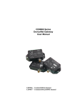
DN120 DeviceNet
Gateway
User’s Manual
DN120
PN 83-210010 Rev B
DN120 DeviceNet Gateway User’s Manual
Table of Contents
CHAPTER 1 – OVERVIEW ..................................................................................................................................... 4
CHAPTER 2 – INSTALLATION ............................................................................................................................. 5
MOUNTING ............................................................................................................................................................... 5
WIRING ..................................................................................................................................................................... 6
DeviceNet Interface............................................................................................................................................. 6
Serial Channel Interface ..................................................................................................................................... 6
Wiring Examples ................................................................................................................................................. 7
CHAPTER 3 – THEORY OF OPERATION ........................................................................................................... 8
GATEWAY OPERATION ............................................................................................................................................. 8
DeviceNet Object Model ..................................................................................................................................... 8
DeviceNet Interface............................................................................................................................................. 9
Serial Channel Interface ................................................................................................................................... 10
Asynchronous Serial Communication .............................................................................................................................11
Status Information ...........................................................................................................................................................11
Receiving Messages ........................................................................................................................................................12
Stream Mode ..............................................................................................................................................................12
Block Mode................................................................................................................................................................12
Returning Received Data............................................................................................................................................13
Padding Message Data ...............................................................................................................................................13
Re-sending Received Data .........................................................................................................................................14
Transmitting Messages ....................................................................................................................................................15
Synchronization...............................................................................................................................................................15
Receive Sequence Number.........................................................................................................................................15
Transmit Sequence Number .......................................................................................................................................15
Synchronous Handshake Protocol ..............................................................................................................................16
CHAPTER 4 – GATEWAY CONFIGURATION ................................................................................................. 18
CONFIGURE DEVICENET INTERFACE....................................................................................................................... 18
DeviceNet Baud Rate Switch ............................................................................................................................. 18
MAC ID Switches .............................................................................................................................................. 18
Serial Channel Baud Rate / Option Switch ....................................................................................................... 19
POWER UP GATEWAY ............................................................................................................................................. 19
DeviceNet Status LEDs ..................................................................................................................................... 19
Serial Channel Status LEDs .............................................................................................................................. 20
Register EDS File.............................................................................................................................................. 20
CONFIGURE SERIAL CHANNEL ................................................................................................................................ 21
CONFIGURE DEVICENET MASTER SCAN LIST ......................................................................................................... 26
Poll Consume Size............................................................................................................................................. 26
Poll Produce Size .............................................................................................................................................. 26
CHAPTER 5 – DEVICENET SPECIFICATIONS................................................................................................ 27
DEVICENET MESSAGE TYPES ................................................................................................................................. 27
DEVICENET CLASS SERVICES ................................................................................................................................. 27
DEVICENET OBJECT CLASSES................................................................................................................................. 27
IDENTITY OBJECT ............................................................................................................................................. 28
ROUTER OBJECT ................................................................................................................................................ 29
DEVICENET OBJECT.......................................................................................................................................... 30
ASSEMBLY OBJECT........................................................................................................................................... 31
CONNECTION OBJECT ...................................................................................................................................... 32
SERIAL STREAM OBJECT................................................................................................................................. 34
CHAPTER 6 – RSNETWORX
CONFIGURATION EXAMPLE .................................................................... 36
CONFIGURE DEVICENET INTERFACE....................................................................................................................... 37
Microscan Systems, Inc.
2
DN120 DeviceNet Gateway User’s Manual
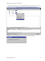
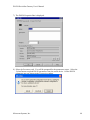
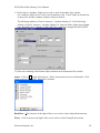
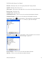
CONNECT & REGISTER EDS FILE ........................................................................................................................... 37
CONFIGURE SERIAL CHANNEL ................................................................................................................................ 45
CONFIGURE DEVICENET MASTER SCAN LIST ......................................................................................................... 52
CHAPTER 7 – CONFIGURATION EXAMPLES ................................................................................................ 59
EXAMPLE 1 – RECEIVING FIXED-LENGTH DATA .................................................................................................... 59
Barcode Scanner ............................................................................................................................................... 59
DN120 Gateway ................................................................................................................................................ 59
EXAMPLE 2 – RECEIVING PRE-DELIMITED DATA ................................................................................................... 61
Barcode Scanner ............................................................................................................................................... 61
DN120 Gateway ................................................................................................................................................ 61
EXAMPLE 3 – RECEIVING POST-DELIMITED DATA ................................................................................................. 63
Barcode Scanner ............................................................................................................................................... 63
DN120 Gateway ................................................................................................................................................ 63
EXAMPLE 4 – TRANSMITTING FIXED-LENGTH DATA .............................................................................................. 65
Bar Code Scanner ............................................................................................................................................. 65
DN120 Gateway ................................................................................................................................................ 65
EXAMPLE 5 – TRANSMITTING VARIABLE-LENGTH DATA ....................................................................................... 67
Bar Code Scanner ............................................................................................................................................. 67
DN120 Gateway ................................................................................................................................................ 67
CHAPTER 8 – TROUBLESHOOTING................................................................................................................. 68
APPENDIX A – PRODUCT SPECIFICATIONS.................................................................................................. 69
DEVICENET INTERFACE .......................................................................................................................................... 69
SERIAL CHANNEL ................................................................................................................................................... 69
ENVIRONMENTAL ................................................................................................................................................... 69
APPENDIX B – DEVICENET TEMPLATE ......................................................................................................... 70
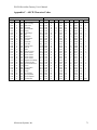
APPENDIX C – ASCII CHARACTER CODES.................................................................................................... 71
Microscan Systems, Inc.
3
DN120 DeviceNet Gateway User’s Manual
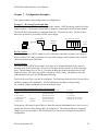
Chapter 1 – Overview
This document describes how to install, configure, and operate the DN120 series of serial to
DeviceNet gateways. The following products are covered in this user manual:
Part Number
DN120
Serial Channel
RS232 full duplex
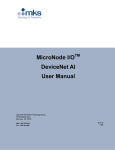
The DN120 gateways allow you to easily interface a wide variety of serial devices to any
DeviceNet industrial control network. Each gateway contains the feature-packed D.I.P.
DeviceNet core. Standard DN120 products are tightly packaged and sealed in a rugged
industrial case. Board-level and customized gateways are also available upon request.
Serial Status LEDs
(RX, TX)
Isolated Serial Channel
(male DB9 connector)
Serial Baud Rate
Rotary Switch
Mounting Holes
DN120
DeviceNet MAC ID
Rotary Switches
DeviceNet Status LEDs
(NET, MOD)
DeviceNet Baud Rate
Rotary Switch
DeviceNet Channel
(male 5-pin micro connector)
Product Features
•
•
•
•
•
•
•
•
•
•
•
•
•
500V isolated serial channel
RS232 with RTS/CTS flow control
XON/XOFF software flow control
300, 600, 1200, 2400, 4800, 9600, 19200 bps serial data rates
Configurable parity
64 byte transmit and receive FIFO buffers
Powered from DeviceNet 24VDC
Loss-of-ground protection circuitry
DeviceNet slave mode supports POLL and EXPLICIT messages
Rotary switches set DeviceNet baud rate and MAC ID
Rotary switch sets serial data rate
4 bi-color status LEDs
Encapsulated circuit board in compact industrial case
Microscan Systems, Inc.
4
DN120 DeviceNet Gateway User’s Manual
Chapter 2 – Installation
This chapter describes how to install and connect the DN120 gateway to a DeviceNet network
and your serial device.
Mounting
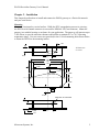
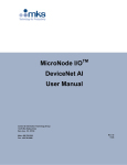
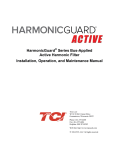
Mount on a horizontal or vertical surface. While the RTV encapsulation protects its circuitry,
the DN120 serial channel connector is not rated for NEMA4 / IP65 environments. Mount the
gateway in a suitable location or enclosure for your application. The gateway will generate up to
1.4W of heat, so provide sufficient clearance and airflow to maintain 0°C to 70°C operating
temperature range. Use two screws (not provided) in the 0.19 inch mounting holes shown below
to fasten the DN120 to the mounting surface.
1.25
All dimensions
are inches
0.65
0.45
3.80
4.30
3.30
0.50
0.12
Mtg. Holes
(2) 0.19 DIA.
1.225
1.225
0.725
0.625 DIA. On Case Wall
0.70
0.542
1.10
Microscan Systems, Inc.
5
DN120 DeviceNet Gateway User’s Manual
Wiring
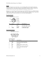
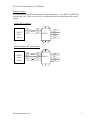
The DN120 requires two connections – one to the DeviceNet network (male 5-pin micro
connector) and one to the target serial device (male DB9 connector). Follow all applicable
electrical codes in your area when mounting and wiring any electrical device.
All power is received from the DeviceNet network. The DN120 draws up to 50mA from the
24VDC power supply. Select your DeviceNet cables and power supply so that it can provide
sufficient current for all networked devices at their peak operating power.
DeviceNet Interface
Male 5-Pin Micro Connector
DRAIN
V+
CAN_L
VPIN
1
2
3
4
5
CAN_H
SIGNAL
DRAIN
V+
VCAN_H
CAN_L
COLOR
NONE
RED
BLACK
WHITE
BLUE
DESCRIPTION
Cable shield or drain wire.
DeviceNet 24VDC(+) power.
DeviceNet 24VDC(-) power.
Communication signal.
Communication signal.
Serial Channel Interface
Male DB9 Serial Connector
1
2
6
3
7
4
8
5
9
DN120 (RS232)
PIN
1
2
3
4
5
6
7
8
9
SIGNAL
NC
RXD
TXD
NC
GND
NC
RTS
CTS
NC
Microscan Systems, Inc.
DESCRIPTION
No Connect. Do not connect any wires to NC pins.
Receive Data. RS232 input signal.
Transmit Data. RS232 output signal.
No Connect.
Ground. Common for RS232 signals.
No Connect.
Request To Send. RS232 output signal.
Clear To Send. RS232 input signal.
No Connect.
6
DN120 DeviceNet Gateway User’s Manual
Wiring Examples
The following are typical DN120 gateway wiring configurations. Your RS232 or RS422/485
interface may vary. Refer to your device’s documentation for the required data and control
signals.
Simple RS232 Interface
RS232
Serial
Device
2 RXD
3 TXD
5 GND
RXD 2
TXD 3
GND 5
DN120
1
2
3
4
5
DRAIN
VDC+
VDCCAN H
CAN L
DN120
1
2
3
4
5
DRAIN
VDC+
VDCCAN H
CAN L
RS232 Interface, HW Flow Control
RS232
Serial
Device
2
3
5
7
8
RXD
TXD
GND
RTS
CTS
Microscan Systems, Inc.
RXD
TXD
GND
RTS
CTS
2
3
5
7
8
7
DN120 DeviceNet Gateway User’s Manual
Chapter 3 – Theory of Operation
This chapter describes how the DN120 gateway operates. You should have a working
knowledge of DeviceNet and asynchronous serial communications before continuing. The Open
DeviceNet Vendors Association (www.odva.com) is a good source for general DeviceNet
information. Refer to your serial device documentation for its protocol information.
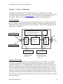
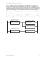
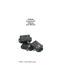
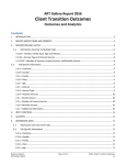
Gateway Operation
The DN120 gateway receives asynchronous serial messages over its serial channel and returns
the received bytes as input data to the DeviceNet master. The gateway transmits bytes sent as
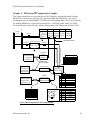
output data from the DeviceNet master out its serial channel. The following diagram shows the
major gateway components.
DeviceNet Poll Command
output data
DC:DC Power Conversion
• 24VDC DeviceNet power input
• VDC for Core & DeviceNet channel
• isolated VDC for serial channel
5-pin male
micro connector
Male DB9
connector
Gateway Core
• microcontroller
• RAM
• Flash ROM
DeviceNet Poll Response
input data
DeviceNet Channel
• 24VDC power
• communications
DeviceNet Object
or Rotary Switches
Configures the DeviceNet
interface baud rate and
MAC ID address.
serial
messages
Serial Channel
• communications
• flow control
Serial Stream Object
Configures the serial channel.
Receives and transmits serial
messages. Controls optional
synchronization.
DeviceNet Object Model
The DeviceNet Specification defines an Object Model that consists of Objects and Attributes.
An Object is a predefined software process, and an Object Attribute is a data value used or
generated by that process. An Object Instance is one occurrence of an Object, operating on its
unique set of Attribute values. The DN120 gateway has six different Object Classes, or types.
Five are standard objects defined by the DeviceNet Specification (Identity, Router, DeviceNet,
Assembly, Connection). One is a device-specific object defined for the DN120 gateway (Serial
Stream). The Serial Stream Object configures and controls the serial channel. It receives and
packages serial data into DeviceNet input bytes, and transmits DeviceNet output bytes as serial
data. Chapter 5 contains detailed information on each DeviceNet object class, instance, and their
associated attributes.
Microscan Systems, Inc.
8
DN120 DeviceNet Gateway User’s Manual
DeviceNet Interface
The DN120 gateway operates as a DeviceNet slave. It supports Explicit Messages and Polled
I/O Messages of the predefined master/slave connection set. The Explicit Unconnected Message
Manager (UCMM) is not supported.
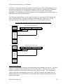
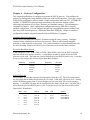
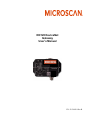
There are four independent processes operating in a DN120 gateway application. The first
process is the exchange of input and output data between the user application program and the
DeviceNet master. The second process is the exchange of input and output data between the
gateway and DeviceNet master, using Polled I/O messaging. The third process is receiving serial
messages and converting it to input data. The fourth process is converting output data and
transmitting it as serial messages.
The DeviceNet Polled I/O Message process consists of the DeviceNet master sending output data
to the DN120 in the form of a Poll Command message, and the DN120 returning input data to
the DeviceNet master in a Poll Response message. The output and input data bytes are typically
mapped into data files inside the DeviceNet master. These data files are exchanged with the user
application program. The application processes the received input data from the gateway and
writes new output data to the DeviceNet master, which sends them to the gateway.
The Polled I/O data exchange typically occurs at a faster rate than the serial transmit and receive
operation, because the DeviceNet baud rate is much greater than the serial channel baud rate.
The DN120 has transmit and receive buffers to handle the slower serial processes. The gateway
also provides synchronization features to ensure delivery of received messages to the application
program, and transmission of application messages out the serial channel.
Input File
Inputs
DeviceNet Poll Response
input data
Receive
Message Packet
Outputs
Output File
DeviceNet Poll Command
output data
DeviceNet
Master
Transmit
Message Packet
Serial
Device
Application
Program
DN120
Gateway
DeviceNet network
Microscan Systems, Inc.
9
DN120 DeviceNet Gateway User’s Manual
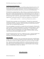
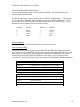
The DN120 configuration defines the number of output bytes in a Poll Command message, and
the number of input bytes in a Poll Response message. Each Poll Command and Poll Response
message can contain up to 2 overhead bytes for DN120 status and data synchronization
information. The remaining bytes contain output data to be transmitted out the serial channel, or
input data received by the serial channel.
The following diagram shows how the input and output bytes map into the Poll Response and
Poll Command messages. The gateway supports a maximum of 67 output bytes in a Poll
Command message, and a maximum of 67 input bytes in a Poll Response message.
DeviceNet Master Mapping of DeviceNet Poll Command and Poll Response Data
DeviceNet Master Outputs
output bytes
DeviceNet Poll Command Message Data
Status Clear
(if enabled)
TX Sequence Number (if
enabled)
Other Output Bytes
(1-65 bytes)
output byte
output byte
output byte
output byte
output byte
output byte
output byte
output byte
output byte
output byte
output byte
output bytes
DeviceNet Master Inputs
input bytes
DeviceNet Poll Response Message Data
Status
(if enabled)
RX Sequence Number (if
enabled)
Other Input Bytes
(1-65 bytes)
input byte
input byte
input byte
input byte
input byte
input byte
input byte
input byte
input byte
input byte
input byte
input bytes
Serial Channel Interface
The DN120 serial channel consists of an asynchronous serial transmitter and receiver. The serial
interface is configured and controlled by the Serial Stream Object. The Serial Stream Object
attributes configure the serial channel baud rate, parity, and flow control. This configuration
applies to both the serial transmitter and receiver. The DN120 gateway has separate 64-byte
serial transmit and receive FIFO buffers, allowing full duplex operation when supported by the
physical layer media.
Microscan Systems, Inc.
10
DN120 DeviceNet Gateway User’s Manual
Asynchronous Serial Communication
Devices communicating on an asynchronous serial link exchange information one bit at a time.
Each bit is transmitted for a specific period of time, defined by the baud rate. Devices use
internal timing circuitry to generate the baud rate. There is no clocking signal between devices
to synchronize the serial data flow, hence the term asynchronous serial communications.
Serial data bits are organized into bytes. When a data byte is asynchronously transmitted, it is
preceded by a start bit, followed by the data bits, an optional parity bit, and one or more stop bits.
There can be a variable transmission delay between successive data bytes, since each byte is
framed by its own start and stop bits. The receiver starts saving bits after is receives a valid start
bit (0), and stops when it receives the expected number of stop bits (1). The data byte’s leastsignificant bit is transmitted first (data bit 0), and the most-significant bit is last (data bit N).
[ start bit ] [ data bit 0 ] [ data bit 1 ] … [ data bit N ] [ optional parity bit ] [ stop bit(s) ]
The parity bit detects single-bit errors in the transmission. The parity bit is calculated and
inserted by the transmitter. The receiver calculates the parity of an incoming byte, and compares
it to the parity bit sent by the transmitter. If the two bit values do not match, then at least one
serial bit value was corrupted during transmission.
Flow control enables the receiving device to regulate the rate of incoming data. Hardware flow
control uses RTS/CTS signals between the devices to control the rate of transmission. Software
flow control uses serial characters XON/OFF to control the rate. CTS Detect Mode uses the
CTS signal to enable serial communications. Flow control helps prevent data loss, if the
receiving device cannot store incoming data fast enough, or if its Receive Buffer is full and
cannot accept more data until existing data is processed.
The DN120 supports baud rates from 300 to 19200 bits per second. It supports 8 data bits with
no parity, 7 data bits with parity, and 1 stop bit. The DN120 model supports RTS/CTS,
XON/XOFF, and CTS Detect Mode flow control options.
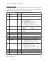
Status Information
The gateway can be configured to return serial channel status information in the Poll Response
message, and receive error-clearing commands in the Poll Command message. When enabled,
the Status byte is returned as an input byte, and the Status Clear byte is received as an output
byte. These bytes contain 8 status bits, defined below. Each bit represents either an error or
state condition for the serial transmitter and receiver. Clearing the associated error bit in the
Status Clear output byte will reset Receive Parity Error, Receive Buffer Overflow, Framing
Error, and Transmit Buffer Overflow error conditions.
Status / Status Clear Bytes
Microscan Systems, Inc.
11
DN120 DeviceNet Gateway User’s Manual
Bit
0
1
2
3
4
5
6
7
Status (1st input byte)
Transmit Channel Blocked
Transmit Buffer Empty
Receive Parity Error
Receive Buffer Empty
Receive Buffer Overflow
Framing Error
Transmit Buffer Overflow
CTS Signal State (1 = asserted)
Status Clear (1st output byte)
not used
not used
Set = 0 to clear Receive Parity Error condition
not used
Set = 0 to clear Receive Buffer Overflow condition
Set = 0 to clear Framing Error condition
Set = 0 to clear Transmit Buffer Overflow condition
not used
A user application can use the Transmit Buffer Empty and Receive Buffer Empty status bits to
monitor the transmitter and receiver states. However, the DN120 gateway also has three data
synchronization features (Receive Sequence Number, Transmit Sequence Number, Handshake
Protocol) that an application can use to better monitor the serial operations.
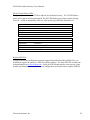
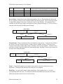
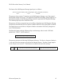
Receiving Messages
The DN120 gateway has two modes for receiving serial data: Stream Mode and Block Mode.
Stream Mode is best suited for applications with fixed-length serial messages, but it can also be
used to capture any stream of serial data. Block Mode is intended for both fixed and variablelength message applications, where a Delimiter byte denotes the beginning or end of a message.
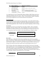
Stream Mode
Stream Mode saves all received message bytes in the Receive Buffer. There is no defined
beginning or end to the message stream. The only limitation is the gateway must send bytes
from the Receive Buffer to the DeviceNet master (Poll Response message) faster than it saves
new message bytes in the Receive Buffer, or the 64-byte buffer may eventually overflow.
Incoming data stream
Stream Mode
0x45 0x62 0x02 0x31 0x32 0x32 0x42 0x45 0x02 0x42 0x43 0x44 …
0x45 0x62 0x02 0x31 0x32 0x32 0x42 0x45 0x02 0x42 0x43 0x44 …
Message Bytes
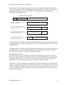
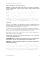
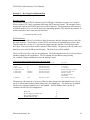
Block Mode
Block Mode uses a configurable Delimiter byte to signal the start or end of a new message
packet. The Delimiter cannot be used in any other part of the message, or it would be incorrectly
interpreted as the start or end of a message. The gateway can be configured to save the Delimiter
byte in the Receive Buffer, or discard it. In Block Mode, the gateway does not return any new
message data to the DeviceNet master until the entire serial message has been received.
The Pre-Delimiter Block Mode configuration expects the Delimiter at the start of a message.
When a Delimiter byte is received, the gateway saves all subsequent bytes in the Receive Buffer
until another Delimiter is received (signaling the start of another message), or until the Maximum
Receive Size number of bytes has been saved. All bytes received after the Maximum Receive
Size and before the next Delimiter are discarded. In this mode, the maximum number of bytes in
a single message is defined by the Maximum Receive Size attribute.
Incoming data stream
Microscan Systems, Inc.
0x45 0x62 0x02 0x31 0x32 0x32 0x42 0x45 0x02 0x42 0x43 0x44 …
12
DN120 DeviceNet Gateway User’s Manual
Pre-Delimiter Mode
Delimiter = 0x02
0x02
Delimiter
0x31 0x32 0x32 0x42 0x45
Message Bytes
0x02
Delimiter
0x42 0x43 0x44 …
Message Bytes
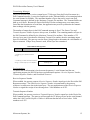
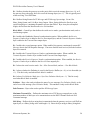
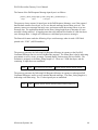
The Post-Delimiter Block Mode configuration expects the Delimiter at the end of a message.
The gateway saves all received bytes in the Receive Buffer until a Delimiter is received. In this
mode, the maximum number of bytes in a single message is limited by the Receive Buffer size
(64 bytes), not the Maximum Receive Size attribute.
Incoming data stream
Post-Delimiter Mode
Delimiter = 0x02
0x45 0x62 0x02 0x31 0x32 0x32 0x42 0x45 0x02 0x42 0x43 0x44 …
0x45 0x62
0x02
Message Bytes
Delimiter
0x31 0x32 0x32f 0x42 0x45
Message Bytes
0x02
Delimiter
0x42 0x43 0x44 …
Message Bytes
Returning Received Data
When the gateway receives a Poll Command message, it removes some or all of the bytes
currently in the Receive Buffer and returns them as input bytes in a Poll Response message.
The Maximum Receive Size attribute defines the maximum number of bytes that can be returned
in a single Poll Response message. If the Receive Buffer contains more bytes than can fit into
one Poll Response message, the remaining bytes are returned in subsequent Poll Response
messages. RX Message is the string of valid message bytes returned in a single Poll Response
message. The RX Message byte string can be formatted as either a Short_String (byte array with
1st byte = length) or a Byte Array (no length byte). The number of bytes in an RX Message string
can be less than or equal to the Maximum Receive Size, but never larger. When the number is
less, the remaining Poll Response input bytes are either padded or undefined.
In Stream Mode, the gateway will always try to fill Poll Response message with bytes from the
Receive Buffer. The only time the RX Message size is less than the Maximum Receive Size is
when there are no more bytes in the Receive Buffer.
In Block Mode, the gateway will not return any data in a Poll Response message unless it has a
complete serial message saved in the Receive Buffer. If the message sizes are small, the gateway
may have several messages saved in the Receive Buffer, depending upon how fast the DeviceNet
master polls the gateway for data. The messages are returned one at a time in a Poll Response
message, regardless of their size. If the message is large, then it is returned in multiple Poll
Response messages.
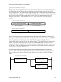
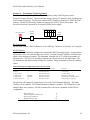
Padding Message Data
Microscan Systems, Inc.
13
DN120 DeviceNet Gateway User’s Manual
If the number of RX Message bytes currently in the Receive Buffer is less than the Maximum
Receive Size number, then the remaining input bytes are undefined. The gateway can optionally
fill the unused input bytes with a Pad character. The Pad characters can be added at the
beginning or end of the message.
Poll Response Message Data
Status
Receive Sequence Number
other input bytes
1. The are enough message bytes in Receive
Buffer to fill Poll Response.
RX Message bytes
2. The are not enough message bytes in
Receive Buffer to fill Poll Response. Unused
input bytes are undefined.
RX Message bytes
undefined
3. The are not enough message bytes in
Receive Buffer to fill Poll Response. Pad bytes
are added after message bytes.
RX Message bytes
Pad Bytes
4. The are not enough message bytes in
Receive Buffer to fill Poll Response. Pad bytes
are added before message bytes.
Pad Bytes
RX Message Bytes
If configured for Pre-Delimiter Block Mode and the Delimiter byte is saved, the Pad characters
are added either after the last valid message byte (right justification) or before the Delimiter byte
(left justification).
If configured for Post-Delimiter Block Mode and the Delimiter byte is saved, the Pad characters
are added either before the first valid message byte (left justification), or after the last valid
message byte but before the Delimiter byte (right justification).
Re-sending Received Data
The DN120 gateway can be configured to return received message bytes only once in a Poll
Response message, and return no data (null value) in subsequent Poll Response messages until
new message bytes are received. For the Short_String data type, a null value consists of the
length byte = 0. For the Byte Array data type, a null value consists of no data.
The gateway can also be configured to always return received message bytes in a Poll Response
message. If no new bytes in the Receive Buffer, then the last received bytes are returned. If new
bytes are in the Receive Buffer, then they are returned. The gateway provides Receive Sequence
Number or Handshake Protocol synchronization options to indicate whether the returned bytes
represent old or new data.
Microscan Systems, Inc.
14
DN120 DeviceNet Gateway User’s Manual
Transmitting Messages
The Serial Stream Object receives output bytes (TX Message) from the DeviceNet master in a
Poll Command message. It saves the output bytes in the Transmit Buffer, to be transmitted when
the serial channel is available. The maximum number of bytes that can be sent in one Poll
Command message is defined by the Maximum Transmit Size attribute. The Transmit Buffer can
hold up to 64 bytes. Because the DeviceNet Polled I/O data exchange may occur many times
faster than the transmission of serial data, the application may need to synchronize the transmit
data exchange with the gateway.
The number of output bytes in the Poll Command message is fixed. The Status Clear and
Transmit Sequence Number bytes are always sent, if enabled. The remaining number of bytes in
the Poll Command is defined by the Maximum Transmit Size attribute. If the number of TX
Message bytes sent is less than the Maximum Transmit Size number, then the remaining output
bytes are undefined. The gateway uses the Short_String length to determine the valid number of
bytes to transmit. If Byte Array format is used, all the bytes are transmitted.
Poll Command Message Data
Status Clear
Transmit Sequence Number
1. TX Message bytes fill Poll Command
message.
2. TX Message is smaller than Poll Command
message. Unused output bytes are undefined.
other output bytes
TX Message bytes
TX Message bytes
undefined
Synchronization
To ensure that no information is lost between the gateway’s serial channel and the user
application program, the DN120 has three synchronization options: Receive Sequence Number,
Transmit Sequence Number, and Handshake Protocol.
Receive Sequence Number
When enabled, the gateway returns a Receive Sequence Number input byte in the DeviceNet Poll
Response message. The 8-bit Receive Sequence Number is incremented by the gateway
whenever it returns new data in the input bytes. The user application uses the Receive Sequence
Number to signal the receipt of new message data. Valid numbers are 0-255.
Transmit Sequence Number
When enabled, the gateway receives a Transmit Sequence Number output byte in the DeviceNet
Poll Command message. The gateway will not send the TX Message bytes out the serial channel
unless the 8-bit Transmit Sequence Number is different than the last received value. Valid
numbers are 0-255.
Microscan Systems, Inc.
15
DN120 DeviceNet Gateway User’s Manual
Synchronous Handshake Protocol
The gateway can be configured with a more robust transmit and receive synchronization process.
The Handshake protocol requires the user application to acknowledge the receipt of new RX
Message input bytes. The protocol also requires the gateway to acknowledge the transmission of
the last TX Message output bytes. When enabled, both the Receive Sequence Number input byte
and Transmit Sequence Number output byte are used. They are segmented into four 4-bit
numbers, shown below. Valid numbers are 1 to 15, with 0 reserved to reset the gateway’s
numbers.
Transmit Sequence Number byte
Receive Acknowledge Number
Bits 4-7 (upper nibble)
Transmit Request Number
Bits 0-3 (lower nibble)
Receive Sequence Number byte
Receive Request Number
Bits 4-7 (upper nibble)
Transmit Acknowledge Number
Bits 0-3 (lower nibble)
The Receive Request Number is incremented by the gateway when it returns new RX Message
input bytes in the Poll Response Message. The gateway will increment from 15 to 1, skipping 0.
The user application acknowledges receipt of this RX Message by setting the Receive
Acknowledge Number equal to the Receive Request Number. The updated Receive Acknowledge
Number is sent back to the gateway in the next Poll Command Message. When the Receive
Acknowledge Number equals the Receive Request Number, the gateway can return the next set of
RX Message. If the user application sends 0 as the Receive Acknowledge Number, the gateway
resets its Receive Request Number to 0.
The following ladder-logic rung shows how the user application program can monitor the
gateway’s Receive Request Number (RX Rqst Num), save the new RX Message bytes, and set
Receive Acknowledge Number (RX Ack Num) equal to Receive Request Number (RX Rqst
Num).
Did gateway increment the RX Rqst
Num, indicating new data?
Save the RX Message bytes.
Compare Function:
RX Rqst Num <> RX Ack Num
Copy Function:
<byte array> = RX Message
Acknowledge receipt of new data.
Copy Function:
RX Ack Num = RX Rqst Num
Microscan Systems, Inc.
16
DN120 DeviceNet Gateway User’s Manual
The Transmit Request Number is incremented by the user application when it sends new TX
Message output bytes in the Poll Command Message. After the gateway transmits these TX
Message bytes, it sets the Transmit Acknowledge Number equal to the Transmit Request Number,
acknowledging the transmission. The updated Transmit Acknowledge Number is returned in the
next Poll Response Message. If the user application sends 0 as the Transmit Request Number,
the gateway ignores the TX Message output bytes and resets its Transmit Acknowledge Number
to 0.
The following ladder-logic rungs show how the user application program writes a new TX
Message value, increments the Transmit Request Number (TX Rqst Num), and waits for the
Transmit Acknowledge Number (TX Ack Num) to equal the Transmit Request Number (TX Rqst
Num). Note the application must wrap the Transmit Request Number from 15 to 1.
Did gateway finish (acknowledge)
transmitting the last message?
Compare Function:
TX Ack Num == TX Rqst Num
Write next output bytes to transmit.
Copy Function:
TX Message = <byte array>
Increment TX Rqst Num (new data)
Addition Function:
TX Rqst Num = TX Rqst Num + 1
If TX Rqst Number greater than 15,
then reset number to 1 (1-15 range)
Compare Function:
TX Rqst Num == 16
Microscan Systems, Inc.
Write Function:
TX Rqst Num = 1
17
DN120 DeviceNet Gateway User’s Manual
Chapter 4 – Gateway Configuration
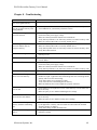
This chapter describes how to configure and operate the DN120 gateway. You configure the
gateway by reading and writing attribute values over its DeviceNet interface. There are a variety
of DeviceNet configuration tools available. Simple configuration tools use GET_ATTRIBUTE
and SET_ATTRIBUTE explicit message commands to read and write attribute values,
addressing each attribute by its Object, Instance, and Attribute numbers. This information is
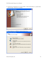
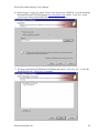
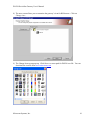
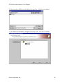
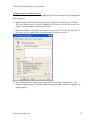
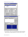
contained in Chapter 5. More sophisticated configuration tools use EDS files to simplify
attribute configuration. You can configure the gateway using pull-down menus, buttons, and
data entry fields from the gateway’s Electronic Data sheet (EDS) file. Chapter 6 contains a
configuration example using the Rockwell Software RSNetworx program.
Configure DeviceNet Interface
Set the DeviceNet Baud Rate and MAC ID Address using the rotary switches. Configure
switches before connecting to the DeviceNet network. There is either a small triangular
indicator or white indicator on the switch. Use a small screwdriver to align that indicator with
the desired setting. Remove the DN120 cover if necessary to access the rotary switches.
DeviceNet Baud Rate Switch
Valid settings are 125K, 250K, 500K, or PGM. When PGM is selected, the DN120 uses the
baud rate saved in its retentive memory. A valid baud rate must be stored before the PGM
selection can be used. The baud rate is stored from the previous DN120 power cycle. It can also
be set over the network (DeviceNet Object Baud Rate attribute).
POSITION
0
1
2
3
4
SETTING
125 Kbps
250 Kbps
500 Kbps
invalid
invalid
POSITION
5
6
7
8
9
SETTING
invalid
invalid
invalid
invalid
PGM
MAC ID Switches
The two MAC ID switches represent decimal numbers from 00 to 99. The LSB switch selects
the Ones digit and the MSB switch selects the Tens digit. Valid MAC IDs are 00 to 63. Setting
a MAC ID address greater than 63 forces the gateway to use the MAC ID saved in retentive
memory. A valid MAC ID must first be stored before this feature can be used. The MAC ID is
stored from the previous DN120 power cycle. It can also be set over the network (DeviceNet
Object MAC ID attribute).
MSB
0
1
2
3
4
5
6
LSB
0 to 9
0 to 9
0 to 9
0 to 9
0 to 9
0 to 9
0 to 3
Microscan Systems, Inc.
Address
00 to 09
10 to 19
20 to 29
30 to 39
40 to 49
50 to 59
60 to 63
MSB
6
7
8
9
LSB
4 to 9
0 to 3
0 to 9
0 to 9
Address
stored address
stored address
stored address
stored address
18
DN120 DeviceNet Gateway User’s Manual
Serial Channel Baud Rate / Option Switch
The DN120 gateway has a rotary switch for the serial channel. This switch has different
functions for the DN120 models.
The DN120 model uses the rotary switch to select the RS232 channel baud rate. Valid settings
are 300, 600, 1200, 2400, 4800, 9600, 19200 bits per second, and PRG (table below). When
PRG is selected, the DN120 uses the Baud Rate attribute in the Serial Stream Object. A valid
baud rate must be written over DeviceNet to this attribute.
POSITION
0
1
2
3
4
SETTING
9600 bps
4800 bps
2400 bps
1200 bps
600 bps
POSITION
5
6
7
8
9
SETTING
300 bps
19200 bps
invalid
invalid
PRG
Power Up Gateway
Connect the gateway to a DeviceNet network to power up the gateway.
DeviceNet Status LEDs
The DN120 gateway has two bi-color status LEDs (NET and MOD) that indicate operational
status. During power-up, the LEDs cycle through a sequence of alternating red and green. After
power-up, the NET LED should be flashing green (or solid green if allocated to a DeviceNet
master) and the MOD LED should be solid green. If this does not occur, disconnect from
DeviceNet and verify all the switch settings. See Chapter 8 for additional troubleshooting topics.
State
Off
Flashing Red
Solid Red
Flashing Green
Solid Green
DeviceNet Status LED (NET)
No power.
Configuration error. Check DeviceNet switch settings.
Unrecoverable error.
Device not allocated to a DeviceNet master.
Normal runtime, device allocated as a slave.
State
Off
Flashing Red
Solid Red
Flashing Green
Solid Green
Module Status LED (MOD)
No power.
Configuration error. Check object attribute settings.
Unrecoverable error.
Not defined.
Normal Operation.
Microscan Systems, Inc.
19
DN120 DeviceNet Gateway User’s Manual
Serial Channel Status LEDs
The gateway has two bi-color LEDs to indicate serial channel activity. The TX LED flashes
green when a packet is being transmitted. The RX LED flashes green when a packet is being
received. A fault is indicated by solid red. After power-up, both LEDs should be off.
State
Off
Flashing Red
Solid Red
Flashing Green
Solid Green
Transmit Status LED (TX)
No data being transmitted
Not defined
Transmit error (parity or overrun error)
Data being transmitted
Not defined
State
Off
Flashing Red
Solid Red
Flashing Green
Solid Green
Receive Status LED (RX)
No data being received
Not defined
Receive error (parity or overrun error)
Data being received
Not defined
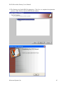
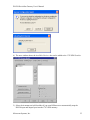
Register EDS File
If using a DeviceNet configuration tool that supports Electronic Data Sheet (EDS) files, you
should now register the gateway’s EDS file with the software. The latest EDS file versions can
be downloaded from www.mksinst.com. Select the EDS file that matches your gateway’s part
number and firmware version. Follow your configuration tool instructions to register EDS file.
Microscan Systems, Inc.
20
DN120 DeviceNet Gateway User’s Manual
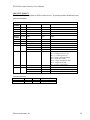
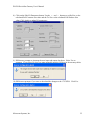
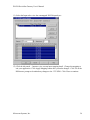
Configure Serial Channel
The Serial Stream Object attributes control the DN120 serial channel. These settings apply to all
serial transmit and receive operations. Before you can set or change any gateway configuration
settings, make sure the gateway is not in the DeviceNet master scanlist.
Serial Stream Object Instance Attributes (Class Code 64)
Data Type
Value
Short_String Received message data. Returned in Poll Response Message.
or
Byte Array
Transmit Data
Short_String Message data to transmit. Received in Poll Command Message.
or
Byte Array
Status
USINT
Bit 0 – Transmit Channel Blocked
Bit 1 – Transmit Buffer Empty
Bit 2 – Receive Parity Error (set = 0 to clear)
Bit 3 – Receive Buffer Empty
Bit 4 – Receive Buffer Overflow Error (set = 0 to clear)
Bit 5 – Framing Error (set = 0 to clear)
Bit 6 – Transmit Buffer Overflow Error (set = 0 to clear)
Bit 7 – CTS Signal State (1 = asserted)
Baud Rate
USINT
0 = 9600 bps
4 = 600 bps
1 = 4800 bps
5 = 300 bps
2 = 2400 bps
6 = 19200 bps
3 = 1200 bps
Parity
USINT
0 = no parity
5 = mark (force to 1)
1 = even parity
6 = space (force to 0)
2 = odd parity
Data Size
USINT
Read-only. 7 bits if parity enabled, 8 bits if no parity.
Stop Bits
USINT
Read-only. Fixed at 1 bit.
Flow Control
USINT
0 = none
2 = CTS / RTS
1 = XON / XOFF
4 = CTS Detect Mode
Receive Count
USINT
Number of bytes in Receive Buffer. Any write clears buffer.
Transmit Count
USINT
Number of bytes in Transmit Buffer. Any write clears buffer.
Maximum Receive Size
USINT
Defines the maximum #bytes returned by RX Message read.
Data Format
USINT
Bit 0 – String Format (0 = Short_String, 1 = Byte Array)
Bit 1 – Strip Parity Bits (0 = retain, 1 = strip)
Bit 2 – Pad Justification (0 = left justify, 1 = right justify)
Bit 3 – Pad Received Message (0 = no, 1 = yes)
Block Mode
USINT
Bit 0 – Pre/Post Delimiter (0 = pre-delimiter, 1 = post-delimiter)
Bit 1 – Strip Delimiter (0 = keep delimiter, 1 = strip delimiter)
Bit 2 – Delimiter Enable (0 = no, 1 = yes)
Bit 3 – Enable Receive Sequence Number (0 = no, 1 = yes)
Bit 4 – Enable Transmit Sequence Number (0 = no, 1 = yes)
Bit 5 – Re-send (0 = no, 1 = yes)
Bit 6 – Synchronization (0 = no, 1 = handshake protocol)
Delimiter
USINT
Delimiter byte value
Pad Character
CHAR
Pad byte value
Maximum Transmit Size
USINT
Defines the maximum # bytes that can be transmitted.
Idle String
Short_String 1-16 byte string transmitted when gateway receives a null Poll
(no input bytes). Short_String length = 0 for no Idle String.
Number
Name
3
Receive Data
4
5
6
7
8
9
10
11
12
13
14
15
16
17
18
19
Microscan Systems, Inc.
21
DN120 DeviceNet Gateway User’s Manual
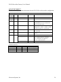
20
Fault String
21
22
23
24
Status Enable
Status Clear Enable
Four Wire
Option Switch
Short_String 1-16 byte string transmitted when gateway’s Polled I/O
connection times out. Short_String length = 0 for no Fault String.
USINT
Set to any nonzero value to enable Status input byte.
USINT
Set to any nonzero value to enable Status Clear output byte.
USINT
NA
USINT
NA
Receive Data – Data from the last valid message packet. Receive Data includes the Status and
Receive Sequence Number bytes if enabled, and the RX Message bytes. The RX Message format
is either Short_String or Byte Array, defined by Data Format attribute. If no message data is
available, the RX Message will be a null packet or Short_String with length = 0. Receive Data is
returned in the DeviceNet Poll Response Message.
Receive Data
Status
Receive Sequence Number
RX Message
Data Format =
xxxxxxx0
Length
Data Format =
xxxxxxx1
Short_String data bytes
Byte Array data bytes
Transmit Data – Data to transmit out the serial channel by the gateway. Transmit Data includes
the Status Clear and Transmit Sequence Number bytes if enabled, and the TX Message bytes.
Format is either Short_String or Byte Array, defined by Data Format attribute. Transmit Data is
typically received in the DeviceNet Poll Command Message. Reading Transmit Data returns the
last byte in the Transmit Buffer.
Transmit Data
Status Clear
Transmit Sequence Number
Data Format =
xxxxxxx0
Length
Short_String data bytes
TX Message
Data Format =
xxxxxxx1
Byte Array data bytes
Status – Contains bit-mapped serial channel status and error bits for transmit and receive
operations. Clearing the bits indicated will clear the error condition.
Baud Rate – Sets the serial channel’s data or baud rate. Enter number from 1-6 to select
corresponding baud rate value. For DN120, the RS232 Baud Rate switch must be set to PRG
before this attribute can be used to set the baud rate.
Microscan Systems, Inc.
22
DN120 DeviceNet Gateway User’s Manual
Parity – Selects the parity type used in the serial byte.
Data Size – Read-only attribute indicates number of data bits in one serial byte. This number
does not include start, parity, or stop bits. If parity is enabled, 7 data bits are used. If no parity, 8
data bits are used.
Stop Bits – Read-only attribute indicates number of stop bits in one serial byte. Fixed at 1.
Flow Control – Selects the method of flow control used across the serial interface.
NONE means there is no flow control over the serial data exchange. The transmitting device can
overflow the receiving device’s buffer.
XON/XOFF is a software flow control option. Receiving device sends an XOFF character to the
transmitting device when its buffer is full, stopping further transmission. It sends an XON
character when it can again receive data. The XOFF and XON characters are not saved as
message data.
CTS/RTS is an RS232 hardware flow control option, available only on the DN120 gateway. The
RTS is an output and CTS is an input signal. The gateway keeps RTS active (low) when it can
receive data. It only transmits data when CTS is active (low).
CTS Detect Mode is an RS232 hardware flow control option, available only on the DN120
gateway. When CTS is asserted, the DN120 serial channel can transmit and receive. When CTS
is not asserted, the DN120 serial channel is disabled and Receive Buffer cleared.
Receive Count – Number of bytes currently available in the Receive Buffer. Writing any value
to this attribute will clear the Receive Buffer.
Transmit Count – Number of bytes currently in the Transmit Buffer. Writing any value to this
attribute will clear the Transmit Buffer.
Maximum Receive Size – Defines the maximum number of data bytes to be returned when the
Receive Buffer is read using either an Explicit Message or a Poll Response Message.
Data Format – Control byte that defines the format of the TX Message and RX Message bytes
transferred across DeviceNet.
Bit 3 selects whether the RX Message bytes are padded with the Pad bytes. Set this bit = 1 to
enable. If there are not enough message bytes in the Receive Buffer to fill up the RX Message
input bytes, then Pad characters are added at either the beginning or end of the message bytes.
Bit 2 selects whether Pad bytes are added at the beginning of the message (0 = left justify) or at
the end of the message (1 = right justify). This bit is used only if the Pad option is enabled.
Microscan Systems, Inc.
23
DN120 DeviceNet Gateway User’s Manual
Bit 1 defines whether the gateway saves the parity bit in received message bytes (set = 0), or if
the gateway forces the parity bit to 0 in received message bytes (set = 1). This is typically used
when receiving 7-bit ASCII data.
Bit 0 defines String Format for TX Message and RX Message byte strings. Set to 0 for
Short_String format, and 1 for Byte Array format. Short_String defines the first byte as an
explicit length byte, containing the number of bytes that follow. Byte Array has an implied
length, derived from the Maximum Receive Size attribute.
Block Mode – Control byte that defines the serial receive mode, synchronization mode, and resend message option.
Bit 6 enables the Handshake Protocol synchronization option. When enabled, the Receive
Sequence Number byte is added to Receive Data input bytes, and the Transmit Sequence Number
byte is added to the Transmit Data output bytes.
Bit 5 enables the re-send message option. When enabled, the gateway continuously returns RX
Message data in the Poll Response message. If no new data has been received, then the last data
bytes are returned.
Bit 4 enables the Transmit Sequence Number synchronization option. When enabled, the
Transmit Sequence Number byte is added to the Transmit Data output bytes.
Bit 3 enables the Receive Sequence Number synchronization option. When enabled, the Receive
Sequence Number byte is added to the Receive Data output bytes.
Bit 2 selects the serial receive mode. Set = 0 for Stream Mode, and set = 1 for Block Mode.
Bit 1 selects whether the Delimiter is saved in the Receive Buffer (set = 0), or it is discarded (set
= 1). This bit is only used when Block Mode is enabled.
Bit 0 selects Pre-Delimiter Mode (set = 0) or Post-Delimiter Mode (set = 1). This bit is only
used when Block Mode is enabled.
Delimiter – Byte value used to indicate the start of a new message (Pre-Delimiter Mode), or the
end of a received message (Post-Delimiter Mode). This attribute is only used in Block Mode.
Pad Character – Byte value used to pad the RX Message bytes.
Maximum Transmit Size – Defines the maximum size of TX Message output bytes, or the
maximum number of data bytes to be transmitted across the RS232 channel from one Poll
Command message.
Idle String – Defines the byte string that is transmitted when the gateway receives a null Poll (no
input bytes, or a Short_String value with length = 0). Enter the byte string in Short_String data
Microscan Systems, Inc.
24
DN120 DeviceNet Gateway User’s Manual
format, with 1st byte = string length. Set the length byte to 0 if you don’t want to transmit an Idle
String. The Idle String can be from 0 to 16 bytes long, not counting Short_String length byte.
Example Idle String is [ 0x01 0x41 ], where string length is 1 and data byte is 0x41 (‘A’). You
must use the RSNetworx Class Instance Editor (Set Attribute Single command) to write a
Short_String attribute value.
Fault String – Defines the byte string that is transmitted when the gateway’s connection to the
DeviceNet master times out. Enter the byte string in Short_String data format, with 1st byte =
string length. Set the length byte to 0 if you don’t want to transmit a Fault String. The Fault
String can be from 0 to 16 bytes long, not counting Short_String length byte.
Example Fault String is [ 0x02 0x42 0x43 ], where string length is 2 and data bytes are 0x42
(‘B’) and 0x43 (‘C’). You must use the RSNetworx Class Instance Editor (Set Attribute
Single command) to write a Short_String attribute value.
Status Enable – Write any nonzero value to include the Status byte in Receive Data input bytes.
Status Clear Enable – Write any nonzero value to include the Status Clear byte in Transmit
Data output bytes.
Microscan Systems, Inc.
25
DN120 DeviceNet Gateway User’s Manual
Configure DeviceNet Master Scan List
You must calculate the number of input and output bytes required by your DN120 configuration
before you can add the gateway to the DeviceNet master scanlist. You need to configure the
DeviceNet master to send the specific number of output bytes in its Poll Command Message, and
receive the specific number of input bytes in the gateway’s Poll Response Message. Once the
input and output bytes are mapped in the DeviceNet master, the user application program will be
able to read and write data values to the input and output bytes.
Poll Consume Size
The Poll Consume Size is the size (in bytes) of the Poll Command Message data field that is sent
by the DeviceNet master to the DN120.
Poll Command data:
[Status Clear byte][Transmit Sequence Number byte][Short_String length byte][TX data bytes (0-64)]
The first 3 bytes are present if enabled. The following equation is used to calculate the DN120
Poll Consume Size. Only include the overhead bytes that are enabled.
+
Status Clear byte
Transmit Sequence Number byte
Short_String length byte
Maximum Transmit Size
1
1
1
____
Poll Consume Size
____
Poll Produce Size
The Poll Produce Size is the size (in bytes) of the Poll Response Message data field that is sent
from the DN120 to the DeviceNet master.
Poll Response data:
[Status byte][Receive Sequence Number byte][Short_String length byte][RX data bytes (0-64)]
The first 3 bytes are present if enabled. The following equation is used to calculate the DN120
Poll Produce Size. Only include the overhead bytes that are enabled.
+
Status byte
Receive Sequence Number byte
Short_String length byte
Maximum Receive Size
1
1
1
____
Poll Produce Size
____
Microscan Systems, Inc.
26
DN120 DeviceNet Gateway User’s Manual
Chapter 5 – DeviceNet Specifications
This chapter describes the DN120 gateway DeviceNet specifications.
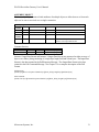
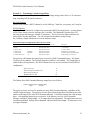
DeviceNet Message Types
The DN120 is a Group 2 Slave Device that supports the following message types.
CAN IDENTIFIER
GROUP 2 MESSAGE TYPE
10xxxxxx111
Duplicate MAC ID Check Message
10xxxxxx110
Unconnected Explicit Request Message
10xxxxxx101
Master I/O Poll Command Message
10xxxxxx100
Master Explicit Request Message
xxxxxx = DN120 MAC ID
DeviceNet Class Services
The DN120 is a Group 2 Slave Device that supports the following class services and instance
services.
SERVICE CODE
05 (0x05)
14 (0x0E)
16 (0x10)
75 (0x4B)
76 (0x4C)
SERVICE NAME
Reset
Get Attribute Single
Set Attribute Single
Allocate Group 2 Identifier Set
Release Group 2 Identifier Set
DeviceNet Object Classes
The DN120 device supports the following DeviceNet object classes.
CLASS CODE
01 (0x01)
02 (0x02)
03 (0x03)
04 (0x04)
05 (0x05)
64 (0x40)
OBJECT TYPE
Identity
Router
DeviceNet
Assembly
Connection
Serial Stream Object
Microscan Systems, Inc.
27
DN120 DeviceNet Gateway User’s Manual
IDENTITY OBJECT
The Identity Object is required on all DeviceNet devices. It provides product identification and
general information.
Identity Object
Class
Access
Attribute
1
Get
2
Get
6
Get
7
Get
Instance Access
Attribute
1
Get
2
Get
3
Get
4
Get
5
Get
6
7
Get
Get
Class Code 01 (0x01)
Name
Type
Value
Revision
Max Object Instance
Max Class Identifier
Max Instance Attribute
Name
UINT
UINT
UINT
UINT
Type
1
1
7
7
Value
Vendor
Product Type
Product Code
Revision
Major Revision
Minor Revision
Device Status
UINT
UINT
UINT
STRUCT of
USINT
USINT
WORD
59 = D.I.P. Products
12 = Communications
1
Serial Number
Product Name
Length
Name
UDINT
STRUCT of
USINT
6
STRING [6]
4
0
Bit 0 = owned (0 available, 1 allocated)
Bit 2 = configured (0 no, 1 yes)
Bit 4-7 = vendor specific (0)
Bit 8 = minor configuration fault
Bit 9 = minor device fault
Bit 10 = major configuration fault
Bit 11 = major device fault
Bit 1, 3, 12-15 = reserved (0)
Unique serial number for every device
Common Services
Service Code
05 (0x05)
14 (0x0E)
Class
No
Yes
Microscan Systems, Inc.
Instance
Yes
Yes
Service Name
Reset
Get_Attribute_Single
28
DN120 DeviceNet Gateway User’s Manual
ROUTER OBJECT
The Message Router Object provides a messaging connection point through which a Client may
address a service to any object class or instance residing in the DN120 device.
Router Object
Class
Access
Attribute
1
Get
6
Get
7
Get
Instance Access
Attribute
2
Get
Class Code 02 (0x02)
Name
Type
Value
Revision
Max Class Identifier
Max Instance Attribute
Name
UINT
UINT
UINT
Type
1
7
2
Value
Number of Connections UINT
2
Common Services
Service Code
14 (0x0E)
Class
Yes
Microscan Systems, Inc.
Instance
Yes
Service Name
Get_Attribute_Single
29
DN120 DeviceNet Gateway User’s Manual
DEVICENET OBJECT
The DeviceNet Object contains information about the DN120 DeviceNet interface configuration.
DeviceNet Object
Class
Access
Attribute
1
Get
Instance Access
Attribute
1
Get/Set
Class Code 03 (0x03)
Name
Type
Value
Revision
Name
UINT
Type
2
Value
MAC ID
USINT
Settable only if MAC ID switches > 63.
Valid numbers are 0 to 63. Returns last
value set or switch value.
2
Get/Set Baud Rate
USINT
Settable only if Baud switch > 2. Valid
settings are 0 = 125K, 1 = 250K, 2 = 500K.
Returns last value set or switch value.
3
Get/Set Bus Off Interrupt
BOOL
4
Get/Set Bus Off Counter
USINT
0 = hold CAN in OFF state (default)
1 = reset CAN
Writing this attribute forces counter value
to zero.
5
Get
Allocation Information
Choice Byte
Master Node Address
STRUCT of
BYTE
USINT
bit 0 = explicit msg, set to 1 to allocate
bit 1 = polled IO, set to 1 to allocate
bit 2 = strobed IO, not supported
bits 3-7 = reserved, set to 0
Allocated to this DeviceNet master
Common Services
Service Code
14 (0x0E)
16 (0x10)
75 (0x4B)
76 (0x4C)
Class
Yes
No
No
No
Microscan Systems, Inc.
Instance
Yes
Yes
Yes
Yes
Service Name
Get_Attribute_Single
Set_Attribute_Single
Allocate Master/Slave
Release Master/Slave
30
DN120 DeviceNet Gateway User’s Manual
ASSEMBLY OBJECT
The Assembly Object instances bind attributes of multiple objects to allow data to or from each
object to be sent or received over a single connection.
Assembly Object
Class
Access
Attribute
1
Get
2
Get
Instance Access
Attribute
3
Get
Class Code 04 (0x04)
Name
Type
Value
Revision
Max Class ID
Name
UINT
UINT
Type
2
2
Value
Data Stream
note 1
Instance 1 for input data stream.
Instance 2 for output data stream.
Common Services
Service Code
14 (0x0E)
16 (0x10)
Class
Yes
No
Instance
Yes
Yes
Service Name
Get_Attribute_Single
Set_Attribute_Single
Instance 1 Input Data Stream and Instance 2 Output Data Stream are structured as either an array of
bytes or as a Short_String consisting of a single byte length field and N data bytes. The Input Data
Stream is the data returned in the Poll Response Message. The Output Data Stream is the data
returned in the Poll Command Message. See Chapter 3 for a complete description of the Poll
Format.
Poll Response:
[Status byte][Receive Sequence Number byte][Short_String Length byte][RX data bytes]
Poll Command:
[Status Clear byte][Transmit Sequence Number byte][Short_String Length byte][TX data bytes]
Microscan Systems, Inc.
31
DN120 DeviceNet Gateway User’s Manual
CONNECTION OBJECT
The Connection Object instances manage the characteristics of each communication connection.
The DN120 is a Group 2 Only Slave device that supports 1 Explicit Message Connection (Instance
1) and 1 Poll Message Connection (Instance 2).
Connection Object
Class
Access
Attribute
1
Get
Instance Access
Attribute
1
Get
Class Code 05 (0x05)
Name
Type
Value
Revision
Name
UINT
Type
1
Value
State
USINT
0 = non-existent
1 = configuring
2 = established
3 = timed out
USINT
0 = Explicit Message
1 = I/O Message
0x83 for Explicit Message
0x82 for I/O Message
Explicit Message:
10xxxxxx011 = produced connection id
I/O Message:
01111xxxxxx = produced connection id
Explicit Message:
10xxxxxx100 = consumed connection id
I/O Message:
10xxxxxx101 = consumed connection id
0x21 for Explicit Message
0x01 for I/O Message
67 for Explicit Message
See Stream Object for I/O Message
71 for Explicit Message
See Stream Object for I/O Message
Default 2500 msec
0 = Timeout (Explicit Message default)
1 = Auto Delete
2 = Auto Reset (I/O Message default)
0 for Explicit Message
6 for I/O Message
Null for Explicit Message
STRUCT for I/O Message
0x20
0x04
0x24
0x01
0x30
0x03
0 for Explicit Message
6 for I/O Message
2
Get
Instance Type
3
Get
Transport Class Trigger USINT
4
Get
Production Connection
UINT
5
Get
Consumed Connection
UINT
6
Get
USINT
7
Get
Initial Communication
Characteristics
Production Size
8
Get
Consumed Size
UINT
9
12
Get/Set Expected Packet Rate
Get/Set Timeout Action
UINT
UINT
USINT
13
Get
Production Path Length USINT
14
Get
Production Path
STRUCT of
Get
Log. Seg., Class
Class Number
Log. Seg., Instance
Instance Number
Log. Seg., Attribute
Attribute Number
Consumed Path Length
USINT
USINT
USINT
USINT
USINT
USINT
USINT
15
Microscan Systems, Inc.
32
DN120 DeviceNet Gateway User’s Manual
16
17
Get
Consumed Path
STRUCT of
Get
Log. Seg., Class
Class Number
Log. Seg., Instance
Instance Number
Log. Seg., Attribute
Attribute Number
Production Inhibit
USINT
USINT
USINT
USINT
USINT
USINT
UINT
Null for Explicit Message
STRUCT for I/O Message
0x20
0x04
0x24
0x02
0x30
0x03
0
Common Services
Service Code
05 (0x05)
14 (0x0E)
16 (0x10)
Class
Yes
Yes
No
Microscan Systems, Inc.
Instance
Yes
Yes
Yes
Service Name
Reset
Get_Attribute_Single
Set_Attribute_Single
33
DN120 DeviceNet Gateway User’s Manual
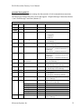
SERIAL STREAM OBJECT
The Serial Stream Object configures the DN120 serial channel.
Serial Stream Object
Class
Access
Attribute
1
Get
2
Get
6
Get
7
Get
Instance
Access
Attribute
3
Get
4
Get/Set
Class Code 64 (0x40)
Name
Type
Value
Revision
Max Object Instance
Max Class Identifier
Max Instance Attribute
Name
UINT
UINT
UINT
UINT
Type
1
1
7
22
Value
Receive Data
Transmit Data
Data Format Received message data. Returned in Poll Response
Data Format Message data to transmit. Received in Poll
Command.
USINT
Bit 0 – Transmit Channel Blocked
Bit 1 – Transmit Buffer Empty
Bit 2 – Receive Parity Error (0 to clear)
Bit 3 – Receive Buffer Empty
Bit 4 – Receive Buffer Overflow Error (0 to clear)
Bit 5 – Framing Error (0 to clear)
Bit 6 – Transmit Buffer Overflow Error (0 to clear)
Bit 7 – CTS Signal State (1 = asserted)
USINT
0 = 9600 bps
4 = 600 bps
1 = 4800 bps
5 = 300 bps
2 = 2400 bps
6 = 19200 bps
3 = 1200 bps
USINT
0 = no parity
5 = mark (force to 1)
1 = even parity
6 = space (force to 0)
2 = odd parity
5
Get/Set
Status
6
Get/Set
Baud Rate
7
Get/Set
Parity
8
9
10
Get
Get
Get/Set
Data Size
Stop Bits
Flow Control
USINT
USINT
USINT
11
12
13
14
Get/Set
Get/Set
Get/Set
Get/Set
Receive Count
Transmit Count
Maximum Receive Size
Data Format
USINT
USINT
USINT
USINT
15
Get/Set
Block Mode
USINT
16
17
18
Get/Set
Get/Set
Get/Set
Delimiter
USINT
Pad Character
CHAR
Maximum Transmit Size USINT
Microscan Systems, Inc.
7 (parity enabled) or 8 (no parity)
1
0 = none
2 = CTS / RTS
1 = XON / XOFF
4 = CTS Detect Mode
Number of bytes in Receive Buffer. Write to clear.
Number of bytes in Transmit Buffer. Write to clear
Maximum # bytes returned by Receive Buffer read.
Bit 0 – String Format (0 = Short_String, 1 = Array)
Bit 1 – Strip Parity Bits (0 = retain, 1 = strip)
Bit 2 – Pad Justification (0 = left, 1 = right)
Bit 3 – Pad Received Message (0 = no, 1 = yes)
Bit 0 – Pre/Post Delimiter (0 = Pre-, 1 = Post-)
Bit 1 – Strip Delimiter (0 = keep, 1 = strip)
Bit 2 – Delimiter Enable (0 = no, 1 = yes)
Bit 3 – Enable Receive Sequence Number
Bit 4 – Enable Transmit Sequence Number
Bit 5 – Re-send (0 = no, 1 = yes)
Bit 6 – Synchronization (0 = no, 1 = yes)
Delimiter byte value
Pad byte value
Defines maximum # bytes that can be transmitted.
34
DN120 DeviceNet Gateway User’s Manual
19
Get/Set
Idle String
20
Get/Set
Fault String
21
22
Get/Set
Get/Set
Status Enable
Status Clear Enable
Short_String Byte string transmitted when gateway receives null
Poll (no input bytes). Length = 0 for no Idle String.
Short_String Byte string transmitted when gateway’s Polled I/O
connection times out. Length=0 for no Fault String
USINT
Nonzero value enables Status input byte.
USINT
Nonzero value enables Status Clear output byte.
Common Services
Service Code
05 (0x05)
14 (0x0E)
16 (0x10)
Class
No
Yes
No
Microscan Systems, Inc.
Instance
Yes
Yes
Yes
Service Name
Reset
Get_Attribute_Single
Set_Attribute_Single
35
DN120 DeviceNet Gateway User’s Manual
Chapter 6 – RSNetworx
Configuration Example
This chapter shows how to set up configure a DN120 gateway using the Rockwell Software
RSNetworx software and your gateway’s Electronic Data Sheet (EDS) file. The system
configuration uses an Allen-Bradley 1770-KFD DeviceNet adapter (MAC ID 62) to connect the
PC running RSNetworx to the DeviceNet network. A SLC500 system with a 1747-SDN
DeviceNet Scanner (MAC ID 00) is the DeviceNet master. DN120 gateway has MAC ID 03.
L
N
Input
Slot 0
Slot 1
SLC502
DeviceNet
PLC CPU
Scanner
Power Sup.
120VAC
24vdc output
Fuse 3A
1747-P1
120/240VAC
Neutral
1747-L524 1747-SDN
Comm.
Comm.
Slot 2
Slot 3
8 pt. Input 8 pt.Output
module
module
1746-IV8
1746-OB8
GND
DeviceNet network
Fuse 1A
24VDC Power Supply
Fuse 6A
+
24VDC
-to pin 1 DeviceNet connector
GND
PC Interface
To PC RS232 25
Module
Pin Serial Interface
1747-PIC
For Used with
RS232-PLC
RSLogic Prog.
RS232 serial
communication
To PC RS232 9 pin
to pin 5 DeviceNet connector
120VAC
PS to DeviceNet Dist.
Pin Color
Description
1 black BUS- (0vdc)
3
clear
Shield (Drain)
5
red
BUS+ (24vdc)
PC Interface Mod.
Serial Interface For
1770-KFD
DIP790 Device
Used with RSLinx,
RS232-DeviceNet
Net Dist. Board
& RSNetWorx Prog.
Terminal Connector
DeviceNet
9 pin DIN RS232 Serial
Gateway Module
Interface to Barcode
DN120
Reader, Scanner
RS232-DeviceNet
Pin Color
1 black
2
Weigh Scale or etc.
RS232 Pin Layout
Pin Func. Pin Func.
2 RXD 7
RTS
3
8
TXD
CTS
5
DeviceNet
Male Connector
4
3
5
GND
Pin 1,4,6,9 are unused
1
2
blue
Description
V- (BUS-)
data low (CAN L)
3
clear
shield (Drain)
4
white
data high (CAN H)
5
red
V+ (BUS+)
DeviceNet Connector
Pin Color
1 clear
Description
shield (Drain)
2
red
3
black
V- (BUS-)
4
white
data high (CAN H)
5
blue
data low (CAN L)
V+ (BUS+)
Figure 1. DN120 Integrated with Allen Bradley SLC500
Microscan Systems, Inc.
36
DN120 DeviceNet Gateway User’s Manual
Configure DeviceNet Interface
Follow instructions in Chapter 4 to set the gateway’s rotary switches to 125Kbps baud rate and
MAC ID to 03. Set the RS232 Baud Rate switch to PRG mode. Connect the gateway to the
DeviceNet network to power it up. During power-up, the NET and MOD LEDs cycle through a
sequence of alternating red and green. After power-up, the NET LED should be flashing green
and the MOD LED should be solid green.
Connect & Register EDS File
1) Start up the RSNetworx program. Select the Online operation from the Network menu.
Microscan Systems, Inc.
37
DN120 DeviceNet Gateway User’s Manual
2) The following text box should pop up, showing the networks connected to your computer.
3) Click on the 1770-KFD-1 + to show all connected DeviceNet devices. The gateway is at
MAC ID 03, verifying its DeviceNet connection. It is an Unrecognized Device until the
gateway’s EDS file is registered with RSNetworx.
Microscan Systems, Inc.
38
DN120 DeviceNet Gateway User’s Manual
4) Click Cancel to close Browse for network window. Select the EDS Wizard… operation from
the Tools menu. Click Next> to continue.
5) Select the Register an EDS file(s) option and click Next>.
Microscan Systems, Inc.
39
DN120 DeviceNet Gateway User’s Manual
6) Select Register a single file option. Browse for your gateway’s EDS file. You can download
the latest EDS and ICON files from the www.microscan.com website. Click Next> when
you have the correct path and EDS file name in the Named: box.
7) The next screen shows the RSNetworx installation test results. Click View file… to view the
actual EDS file text. Click Next> to continue.
Microscan Systems, Inc.
40
DN120 DeviceNet Gateway User’s Manual
8) The next screen allows you to customize the gateway’s icon for RSNetworx. Click on
Change icon…
9) The Change Icon screen pops up. Click Browse to enter path for DN120 icon file. You can
download the icon file from www.microscan.com.
Microscan Systems, Inc.
41
DN120 DeviceNet Gateway User’s Manual
10) Enter the path to DN120 icon file in the File name: box. Click Open to continue.
11) The DN120 icon should have changed to the proper icon. Click Next to continue.
Microscan Systems, Inc.
42
DN120 DeviceNet Gateway User’s Manual
12) The final step is to finish EDS file registration. Click Next> to complete the registration
process. Click Finish to close the EDS Wizard window.
Microscan Systems, Inc.
43
DN120 DeviceNet Gateway User’s Manual
13) Repeat steps 1, 2, and 3 to browse the DeviceNet network. RSNetworx should now
recognize the device at MAC ID 03 as a DN120 gateway, and display the DN120 icon. Click
Cancel when finished.
Microscan Systems, Inc.
44
DN120 DeviceNet Gateway User’s Manual
Configure Serial Channel
Once the gateway is connected to DeviceNet and communicating with RSNetworx, you can
configure its serial channel. Make sure the gateway is not in the DeviceNet master scanlist
before changing any attribute values.
The Serial Stream Object attributes control the gateway’s serial channel transmit and receive
operations. The following steps show how to configure the Serial Stream Object attributes using
the RSNetworx program.
1) Select the Online operation from the Network menu. Select the DeviceNet adapter (1770KFD-1 in this example) and click OK.
2) RSNetworx prompts you to upload the network configuration. Click OK to continue.
Microscan Systems, Inc.
45
DN120 DeviceNet Gateway User’s Manual
3) RSNetworx displays the following text box while it uploads the network configuration.
4) The following screen displays the online nodes.
Microscan Systems, Inc.
46
DN120 DeviceNet Gateway User’s Manual
5) Left-click on the DN120 icon to select it. Right-click and select Properties from the pop-up
menu. You can also double-click on the DN120 icon to open its properties box.
6) RSNetworx displaces the following text box while is reads DN120 EDS file.
Microscan Systems, Inc.
47
DN120 DeviceNet Gateway User’s Manual
7) The DN120 Properties Box is displayed.
8) Select the Parameters tab. You will be prompted for the parameters source. Select the
Upload button to upload DN120 parameters from the actual device. All the DN120
parameters are now shown in the Properties window.
Microscan Systems, Inc.
48
DN120 DeviceNet Gateway User’s Manual
9) You may now edit the Serial Stream Object attributes in this window
Note that the Idle String and Fault String attributes are not listed. These attributes use
Short_String data type, which is not supported by RSNetworx EDS File interface.
10) Use the Class Instance Editor to configure Short_String attributes.
Microscan Systems, Inc.
49
DN120 DeviceNet Gateway User’s Manual
11) Select the Set_Attribute_Single service code to write an attribute value, and the
Get_Attribute_Single service code to read an attribute value. Check Values in decimal box
to enter class, instance, attribute, and data values in decimal.
The Idle String address is Class 64, Instance 1, Attribute Number 19. The Fault String
address is Class 64, Instance 1, Attribute Number 20. Enter the Short_String data as length
byte, then data bytes. Example is [0x01 0x02] for a single byte string 0x02 (ASCII STX).
12) Enter the remaining Serial Stream Object attributes in the Parameters Box window.
Status – Click on … to open selection box. Shows current status and error information. Click
on any errors to clear check. Press OK to continue.
Baud Rate – Click on arrow to the right of the current value to select from pull-down menu.
Parity – Click on arrow to the right of the current value to select from pull-down menu.
Microscan Systems, Inc.
50
DN120 DeviceNet Gateway User’s Manual
Data Size – Read-only value, set to 8 if no parity selected and 7 if party selected.
Stop Bit – Read-only value, always set to 1.
Flow Control – Click on arrow to the right of the current value to select from pull-down menu.
Receive Count – Read-only value.
Transmit Count – Read-only value.
Maximum Receive Size – Click on current value and enter desired number in decimal.
Maximum Transmit – Click on current value and enter desired number in decimal.
Data Format – Click on … to open selection box. Click on check box to select the desired
option. The Delimiter Mode uses bits 0, 1, 2, 3 of the byte. Ignore bits 4 through 7.
Block Mode – Click on … to open up selection box. Click on check box to set or clear the
desired bit. The Serial Status byte uses bits 0 through 6. Ignore bit 7.
Receive Delimiter – Click on current value and enter number in decimal.
Pad Char – Click on current value and enter number in decimal.
Microscan Systems, Inc.
51
DN120 DeviceNet Gateway User’s Manual
Configure DeviceNet Master Scan list
After all the object instances have been configured, the DeviceNet master can be configured to
poll the gateway.
1) Before using the RSNetworx to map the gateway’s Polled I/O connection to 1747-SDN
DeviceNet master scanner, you must calculate the Poll Produce Size & Poll Consume Size.
Chapter 4 describes how to calculate these values.
2) Double click on the 1747-SDN icon to open its Properties box. You can also left click on
the icon to select it, right click for the pop-up menu, and select Properties.
3) Select the Scan list tab. RSNetworx prompts you for the Scanner Configuration. Click
Upload to upload current 1747-SDN configuration from the node. RSNetworx displays the
upload progress.
Microscan Systems, Inc.
52
DN120 DeviceNet Gateway User’s Manual
4) The next window shows the Available Devices: that can be added to the 1747-SDN Scanlist.
5) Select the Automap on Add checkbox if you want RSNetworx to automatically map the
DN120 input and output bytes into the 1747-SDN memory.
Microscan Systems, Inc.
53
DN120 DeviceNet Gateway User’s Manual
6) Select the DN120 under Available Devices: and click the > button to transfer to Scanlist.
7) RSNetworx warns that the DN120 does not contain any I/O data. Click OK to continue.
Microscan Systems, Inc.
54
DN120 DeviceNet Gateway User’s Manual
8) Click on the Edit I/O Parameters button. Use the ∧ and ∨ buttons to set Rx Size: to the
calculated Poll Consume Size value and the Tx Size: to the calculated Poll Produce Size
value. Click Apply to update I/O parameters.
9) RSNetworx prompts to Automap the new input and output data bytes. Select Yes to
automap. If you select No, then you must manually map the I/O bytes in the memory tables.
10) RSNetworx prompts if you want to download the changes to the 1747-SDN. Click Yes.
Microscan Systems, Inc.
55
DN120 DeviceNet Gateway User’s Manual
11) Select the Input tab to view the automapped DN120 input bytes.
12) Click the Advanced… button to view current input mapping detail. Change the mapping to
suit your application. Click Apply Mapping button after you make changes. Click Yes at the
RSNetworx prompt to download any changes to the 1747-SDN. Click Close to continue.
Microscan Systems, Inc.
56
DN120 DeviceNet Gateway User’s Manual
13) Select the Output tab to view the automapped DN120 output bytes.
14) Click the Advanced… button to view current input mapping detail. Change the mapping to
suit your application. Click Apply Mapping button after you make changes. Click Yes at the
RSNetworx prompt to download any changes to the 1747-SDN. Click Close to continue.
Microscan Systems, Inc.
57
DN120 DeviceNet Gateway User’s Manual
Microscan Systems, Inc.
58
DN120 DeviceNet Gateway User’s Manual
Chapter 7 – Configuration Examples
This chapter contains four example gateway configurations.
Example 1 – Receiving Fixed-Length Data
Read UPC labels into a PLC using a serial barcode scanner, a DN120 gateway, and a DeviceNet
scanner (master). The barcode scanner RS232 channel is connected to a DN120 serial channel.
The DN120 DeviceNet channel is connected to the PLC DeviceNet scanner. The DeviceNet
network is powered by an external 24VDC power supply.
Barcode Scanner
PLC & DeviceNet Scanner
CDN066
Gateway
Power
Supply
UPC labels
RS232
DeviceNet network
Barcode Scanner
The barcode scanner’s RS232 channel is set for 9600 bps, 8 data bits, no parity, and 1 stop bit.
When it reads a UPC label, it transmits a 5-byte serial message, which consists of the 5 ASCII
characters printed on the UPC label.
DN120 Gateway
The receive mode will be Stream Mode, since there is no defined Delimiter for the start of a
message or the end of a message. All received data bytes will be returned as DeviceNet input
bytes. The Maximum Receive Size is 5, because the Barcode Scanner messages have a fixed
length of 5 bytes. The data bytes will be returned as a Short_String. The gateway will only
return the data bytes once in a Poll Response Message.
The Serial Stream Object can now be configured. The following shows the Serial Stream Object
attribute settings for this application. The 3rd column lists the address string if using
Set_Attribute_Single commands to write the attribute values.
Serial Stream Object Configuration (Class Code 64 or 0x40)
Attribute
6. Baud Rate
7. Parity
10. Flow Control
13. Max Receive Size
14. Data Format
15. Block Mode
Data
0
0
2
5
00000001
00000000
Class / Instance / Attribute / Data
0x40 0x01 0x06 0x00
0x40 0x01 0x07 0x00
0x40 0x01 0x0A 0x02
0x40 0x01 0x0D 0x05
0x40 0x01 0x0E 0x01
0x40 0x01 0x0F 0x00
Description
0 = 9600 bps
0 = no parity
2 = CTS / RTS
Fixed message size of 5 bytes
String Format = Short_String
The gateway will return 6 bytes of Receive Data, because the Maximum Receive Size is set to 5
and the data format is Short String (add 1 for length byte). The Status and Receive Sequence
Number bytes are not enabled. The Poll Produce Size can now be calculated for this DN120
configuration.
Microscan Systems, Inc.
59
DN120 DeviceNet Gateway User’s Manual
+
Status byte
Receive Sequence Number byte
Short_String length byte
Maximum Receive Size
Poll Produce Size
0
0
1
5
6
The format of the Poll Response Message input bytes is as follows:
[ Short_String length ] [ Short_String data ]
1 byte
5 bytes
The gateway always returns 6 input bytes in the Poll Response Message, even if a new barcode
message has not been received. The gateway will return new message data only once, and return
a null data string if there is no new message data. The application should check the Short_String
length byte to determine if a new message is being returned. A length of 5 indicates valid data
bytes (new message data). A length of 0 indicates no valid data bytes (no new message).
The Barcode Scanner sends the following 5-byte serial message when it reads a UPC label
printed with ‘12345’ (ASCII numbers).
0x31 0x32 0x33 0x34 0x35
The gateway generates the following Poll Response Message in response to the first Poll
Command Message after its receives the Barcode message. The Short_String length is 5, since 5
bytes were received.
0x05
0x31 0x32 0x33 0x34 0x35
The gateway generates the following Poll Response Message in response to subsequent Poll
Command Messages, until it receives another Barcode message. The Short_String length is 0,
indicating a null data string. The 5 data bytes are undefined.
0x00
XX XX XX XX XX
Microscan Systems, Inc.
60
DN120 DeviceNet Gateway User’s Manual
Example 2 – Receiving Pre-Delimited Data
Same configuration as Example 1.
Barcode Scanner
The barcode scanner’s RS232 channel is set for 9600 bps, 8 data bits, no parity, and 1 stop bit.
When it reads a UPC label, it transmits following ASCII message format. The message always
begins with the ASCII STX start-of-text (0x02) character. The barcode data will consist of a
variable number of 1 to 14 ASCII characters, depending upon the UPC label being scanned. It
will not transmit a 0x02 in the barcode data field.
[ STX ] [ ASCII barcode data ]
DN120 Gateway
The receive mode will be Pre-Delimiter Mode, because the barcode messages always begin with
the same character. The Delimiter is 0x02 (STX). The Maximum Receive Size is 15, because the
largest message contains 1 STX byte and 14 ASCII bytes. The received bytes will be returned as
a Short_String. An ASCII NUL Pad character (0x00) will be added at the end of the message if
needed. The gateway will always return the data bytes in the Poll Response Message. The
Receive Sequence Number will be used to indicate when a new message is returned.
The Serial Stream Object can now be configured. The following shows the Serial Stream Object
attribute settings for this application. The 3rd column lists the address string if using
Set_Attribute_Single commands to write the attribute values.
Serial Stream Object Configuration (Class Code 64 or 0x40)
Attribute
6. Baud Rate
7. Parity
10. Flow Control
13. Max Receive Size
14. Data Format
Data
0
0
2
15
00001101
Class / Instance / Attribute / Data
0x40 0x01 0x06 0x00
0x40 0x01 0x07 0x00
0x40 0x01 0x0A 0x02
0x40 0x01 0x0D 0x0F
0x40 0x01 0x0E 0x0D
15. Block Mode
00101101
0x40 0x01 0x0F 0x2D
16. Delimiter
17. Pad Character
STX
NUL
0x40 0x01 0x10 0x02
0x40 0x01 0x11 0x00
Description
0 = 9600 bps
0 = no parity
2 = CTS / RTS
Receive messages up to 15 bytes
Pad receive message
Pad justification = right (end of msg)
String Format = Short_String
Re-send = enabled
Receive Sequence Number = enabled
Delimiter = enabled
Pre-Delimiter
0x02 = ASCII STX character
0x00 = ASCII NUL character
The gateway will return up to 16 bytes of Receive Data, because the Maximum Receive Size is
set to 15 and the data format is Short String (add 1 for length byte). The Status byte is not
enabled. The Receive Sequence Number byte is enabled. The Poll Produce Size can now be
calculated for this DN120 configuration.
+
Status byte
Receive Sequence Number byte
Short_String length byte
Maximum Receive Size
Poll Produce Size
Microscan Systems, Inc.
0
1
1
15
17
61
DN120 DeviceNet Gateway User’s Manual
The format of the Poll Response Message input bytes is as follows:
[ Receive Sequence Number ] [ Short_String length ] [ Short_String data ] [ Pad bytes ]
1 byte
1 byte
0-15 bytes
The gateway always returns 17 input bytes in the Poll Response Message, even if the scanned
barcode data contains fewer bytes. The application should check the Short_String length byte to
determine the number of valid data bytes being returned in a particular Poll Response Message.
The remaining input bytes have undefined values.
The gateway will always return the last received Short_String data in its Poll Response Message.
The gateway increments the Receive Sequence Number when new Short_String data is returned.
The application can use the Receive Sequence Number to determine if the Short_String data is
new or old information.
The Barcode Scanner sends the following 8-byte serial message when it reads a UPC label
printed with ‘1234567’ (ASCII numbers).
0x02 0x31 0x32 0x33 0x34 0x35 0x36 0x37
The gateway generates the following Poll Response Message. The Receive Sequence Number is
1, since this is the first message received from the Barcode Scanner. The Short_String length is
8, since 8 bytes were received. 7 Pad characters are added at the end of the message.
0x01
0x08
0x02 0x31 0x32 0x33 0x34 0x35 0x36 0x37
Microscan Systems, Inc.
0x00 0x00 0x00 0x00 0x00 0x00 0x00
62
DN120 DeviceNet Gateway User’s Manual
Example 3 – Receiving Post-Delimited Data
Same configuration as Example 1.
Barcode Scanner
The barcode scanner’s RS232 channel is set for 9600 bps, 8 data bits, no parity, and 1 stop bit.
When it reads a UPC label, it transmits following ASCII message format. The message always
begins ends with the ASCII ETX end-of-text (0x03) character. The barcode data will consist of
a variable number of 1 to 14 ASCII characters, depending upon the UPC label being scanned. It
will not transmit a 0x03 in the barcode data field.
[ ASCII barcode data ] [ ETX ]
DN120 Gateway
The receive mode will be Post-Delimiter Mode, because the barcode messages always end with
the same character. The Delimiter is 0x03 (ETX), and will not be included in the receive data.
The Maximum Receive Size is 15, because the largest message contains 14 ASCII bytes and 1
ETX byte. The received bytes will be returned a Short String. The gateway will only return new
data bytes once in the Poll Response Message. The Status byte will be enabled.
The Serial Stream Object can now be configured. The following shows the Serial Stream Object
attribute settings for this application. The 3rd column lists the address string if using
Set_Attribute_Single commands to write the attribute values.
Serial Stream Object Configuration (Class Code 64 or 0x40)
Attribute
6. Baud Rate
7. Parity
10. Flow Control
13. Max Receive Size
14. Data Format
15. Block Mode
Data
0
0
2
15
00000001
00000110
Class / Instance / Attribute / Data
0x40 0x01 0x06 0x00
0x40 0x01 0x07 0x00
0x40 0x01 0x0A 0x02
0x40 0x01 0x0D 0x0F
0x40 0x01 0x0E 0x01
0x40 0x01 0x0F 0x06
16. Delimiter
ETX
0x40 0x01 0x10 0x03
Description
0 = 9600 bps
0 = no parity
2 = CTS / RTS
Receive messages up to 15 bytes
String Format = Byte Array
Delimiter = enabled
Strip Delimiter enabled
Post-Delimiter
0x03 = ASCII ETX character
The gateway will return up to 16 bytes of Receive Data, because the Maximum Receive Size is
set to 15 and the data format is Short String (add 1 for length byte). The Status byte is enabled.
The Receive Sequence Number byte is not enabled. The Poll Produce Size can now be
calculated for this DN120 configuration.
+
Status byte
Receive Sequence Number byte
Short_String length byte
Maximum Receive Size
Poll Produce Size
Microscan Systems, Inc.
1
0
1
15
17
63
DN120 DeviceNet Gateway User’s Manual
The format of the Poll Response Message input bytes is as follows:
[ Status ] [ Short_String length ] [ Short_String data ] [ undefined bytes ]
1 byte
1 byte
0-15 bytes
The gateway always returns 16 input bytes in the Poll Response Message, even if the scanned
barcode data contains fewer bytes, or if a new barcode message has not been received. The
gateway returns new message data only once, and returns a null data string if there is no new
message data. The application should use the Short_String length byte to determine if a new
message is being returned. A length greater than zero indicates the number of valid data bytes
(new message data). A length of 0 indicates no valid data bytes (no new message).
The Barcode Scanner sends the following 6-byte serial message when it reads a UPC label
printed with ‘12345’ (ASCII numbers).
0x31 0x32 0x33 0x34 0x35 0x03
The gateway generates the following Poll Response Message in response to the first Poll
Command Message after its receives the Barcode message. The Status Byte is 0x0A, indicating
no transmit or receive errors, an empty Transmit Buffer, and an empty Receive Buffer. The
Delimiter is stripped, so the Short_String length is 5. There are 5 valid data bytes, and the
remaining 10 input bytes are undefined.
0x0A
0x05
0x31 0x32 0x33 0x34 0x35
XX XX XX XX XX XX XX XX XX XX
The gateway generates the following Poll Response Message in response to subsequent Poll
Command Messages, until it receives another Barcode message. The Short_String length is 0,
indicating a null data string. The 15 other input bytes are undefined.
0x0A
0x00
Microscan Systems, Inc.
XX XX XX XX XX XX XX XX XX XX XX XX XX XX XX
64
DN120 DeviceNet Gateway User’s Manual
Example 4 – Transmitting Fixed-Length Data
Print an ASCII string from a PLC to a bar code scanner, using a DN120 gateway and a
DeviceNet scanner (master). The text message string is always 25 characters long, including any
ASCII control characters. The bar code scanner RS232 channel is connected to a DN120 serial
channel. The DN120 DeviceNet channel is connected to the PLC DeviceNet scanner. The
DeviceNet network is powered by an external 24VDC power supply.
PLC & DeviceNet Scanner
Bar Code Scanner
DN120
Gateway
Power
Supply
DeviceNet network
RS232
Bar Code Scanner
The bar code scanner’s RS232 channel is set for 9600 bps, 7 data bits, even parity, and 1 stop bit.
DN120 Gateway
The DN120 serial channel is configured to transmit this RS232 message format. A string format
will be Byte Array, since the message size is fixed. Transmit Sequence Numbers will be used to
signal a new message to transmit. The Maximum Transmit Size is 25, which is the number of
message bytes. The Serial Stream Object attributes are shown below for this application. The
3rd column lists the address string if using Set_Attribute_Single commands to write the attribute
values.
Serial Stream Object Configuration (Class Code 64 or 0x40)
Attribute
6. Baud Rate
7. Parity
10. Flow Control
14. Data Format
15. Block Mode
18. Max Transmit Size
Data
5
1
1
00000000
00010000
25
Class / Instance / Attribute / Data
0x40 0x01 0x06 0x05
0x40 0x01 0x07 0x01
0x40 0x01 0x0A 0x01
0x40 0x01 0x0E 0x00
0x40 0x01 0x0F 0x10
0x40 0x01 0x12 0x19
Description
5 = 300 bps
1 = Even parity
1 = XON / XOFF
String Format = Byte Array
Transmit Sequence Number enabled
Fixed message size of 25 bytes
The gateway will transmit 25 output bytes received in a Poll Command Message. The Status
Clear byte is not enabled. The Transmit Sequence Number is enabled. The Length Byte is not
enabled (Byte Array format). The Poll Consume Size can now be calculated for this DN120
configuration.
+
Status Clear byte
Transmit Sequence Number byte
Short_String length byte
Maximum Receive Size
Poll Produce Size
Microscan Systems, Inc.
0
1
0
25
26
65
DN120 DeviceNet Gateway User’s Manual
The format of the Poll Command Message output bytes is as follows:
[ Transmit Sequence Number ] [ message data ]
1 byte
25 bytes
The gateway always receives 26 output bytes in the Poll Command Message. It will not transmit
a new serial message until the Transmit Sequence Number received in the Poll Command is
different than the number received in a previous Poll Command. The application should
increment the Transmit Sequence Number when it sends new output byte values in the Poll
Command Message, to enable the transmission of the new message.
Microscan Systems, Inc.
66
DN120 DeviceNet Gateway User’s Manual
Example 5 – Transmitting Variable-Length Data
Same configuration as Example 4, except the text message string can be from 1 to 25 characters
long, including ASCII control characters.
Bar Code Scanner
The bar code scanner’s RS232 channel is set for 9600 bps, 7 data bits, even parity, and 1 stop bit.
DN120 Gateway
The DN120 serial channel is configured to transmit this RS232 message format. A string format
will be Short_String, since the message size is variable. The Maximum Transmit Size is 25,
since the largest text message contains 25 characters. The Serial Stream Object attributes are
shown below for this application. The 3rd column lists the address string if using
Set_Attribute_Single commands to write the attribute values.
Serial Stream Object Configuration (Class Code 64 or 0x40)
Attribute
6. Baud Rate
7. Parity
10. Flow Control
14. Data Format
15. Block Mode
18. Max Transmit Size
Data
5
1
1
00000001
00000000
25
Class / Instance / Attribute / Data
0x40 0x01 0x06 0x05
0x40 0x01 0x07 0x01
0x40 0x01 0x0A 0x01
0x40 0x01 0x0E 0x01
0x40 0x01 0x0F 0x00
0x40 0x01 0x12 0x19
Description
5 = 300 bps
1 = Even parity
1 = XON / XOFF
String Format = Short_String
Transmit Sequence Number disabled
Fixed message size of 25 bytes
The gateway will transmit the output bytes received in a Poll Command Message. The Status
Clear byte is not enabled. The Transmit Sequence Number is not enabled. The Length Byte is
enabled (Short_String format). The Poll Consume Size can now be calculated for this DN120
configuration.
+
Status Clear byte
Transmit Sequence Number byte
Short_String length byte
Maximum Receive Size
Poll Produce Size
0
0
1
25
26
The format of the Poll Command Message output bytes is as follows:
[ Short_String length ] [ message data ]
1 byte
25 bytes
The gateway always receives 26 output bytes in the Poll Command Message, regardless of the
variable length messages. The gateway uses the Short_String length byte to determine the valid
number of message bytes in the Poll Command Message. It will only transmit the valid message
bytes. All remaining output bytes are ignored. If the gateway receives a Poll Command
Message with Short_String length = 0, no output bytes are transmitted. The application can send
variable-length Short_Strings to be transmitted, and send Null Data (length = 0) when there is no
message to transmit.
Microscan Systems, Inc.
67
DN120 DeviceNet Gateway User’s Manual
Chapter 8 – Troubleshooting
Problem
DeviceNet Configuration Program •
does not recognize Gateway.
Possible Cause
Register Gateway EDS file with Configuration Program.
DeviceNet Configuration Program •
does not recognize Gateway after
loading EDS file.
Check Major and Minor Revisions for Gateway and EDS file, to see if you have
correct EDS file for your Gateway's firmware version.
Gateway does not appear on
DeviceNet network.
•
•
•
•
•
Check wiring and cable connections.
Check DeviceNet power supply voltage.
Make sure Gateway baud rate matches network baud rate.
Verify Gateway baud rate is set from rotary switches or retentive memory value.
Make sure Gateway MAC ID is not used by another device.
After setting Gateway MAC ID,
DeviceNet Master does not
recognize Gateway.
•
•
•
•
Disconnect Gateway from network before changing MAC ID.
Make sure Gateway MAC ID is not used by another device.
Verify Gateway MAC ID is set from rotary switches or retentive memory value.
Verify DeviceNet baud rate.
NET LED is flashing red.
•
Gateway is removed from DeviceNet Master scanlist or network. Power cycle
Gateway to reset.
NET LED is solid red.
•
Make sure Gateway MAC ID is not used by another device. Possible DeviceNet
network failure.
NET LED is off.
•
•
•
•
Check wiring and cable connections.
Check DeviceNet power supply voltage.
Make sure Gateway baud rate matches network baud rate.
Verify Gateway baud rate is set from rotary switches or retentive memory value.
MOD LED is flashing or solid red. •
Gateway has failed. Cycle power to reset. Replace Gateway if necessary.
RX LED does not flash green when •
data is sent to the Gateway.
If Sync enabled, make sure Receive Request Number and Receive Acknowledge
Number are equal. Application must acknowledge last received message before
gateway will receive the next message.
Verify data is being received in Receive Data.
Verify source device is transmitting data to Gateway.
Make sure hardware flow control signals are properly connected.
•
•
•
RX LED is solid red after Gateway •
receives data.
•
Check Status byte for any Receiver errors. Reset Gateway or clear Status error
bits if necessary.
Make sure parity is set to match transmitting device settings.
TX LED is solid red after receiving •
data from DeviceNet Master.
•
Check Status byte for Transmitter errors. Reset Gateway or clear Status error
bits if necessary.
Make sure parity is set to match receiving device settings.
TX LED does not flash green when •
Gateway should be transmitting
data.
•
1747-SDN Scanner displays error •
code 77.
If Transmit Sequence Number enabled, make sure number is being incremented
by the application. Gateway will not transmit new data unless the Transmit
Sequence Number is changed.
Verify data is being saved in Transmit Data.
Gateway Poll Produce Size and/or Poll Consume Size value do not 1747-SDN
Poll Rx/Tx settings.
Microscan Systems, Inc.
68
DN120 DeviceNet Gateway User’s Manual
Appendix A – Product Specifications
DeviceNet Interface
Power Requirements:
Loss of Ground:
Reverse Polarity:
Signal Levels:
11 - 28 Vdc @ 50 mA
Yes
-30 Vdc
ISO11898
Serial Channel
Isolation:
ESD Protection:
Overload Protection:
Short Circuit:
RS232 Output Levels:
500 Volts
+/- 10 kV
+/- 30 Volts
Indefinite
+/- 7.9 Volts (unloaded, typical)
Environmental
Operating Temperature:
Storage Temperature:
Size (inches):
Mounting (inches)
PCB Encapsulation:
0o C to 70o C
-25o C to 85o C
3.25 x 2.37 x 1.08
0.5 tabs, 3/16 diameter mounting holes
RTV Silicon Compound
Microscan Systems, Inc.
69
DN120 DeviceNet Gateway User’s Manual
Appendix B – DeviceNet Template
Class
Instance
Attribute
Microscan Systems, Inc.
Default
Setting
Unit
Comments
70
DN120 DeviceNet Gateway User’s Manual
Appendix C – ASCII Character Codes
Non-Printable Characters
Printable Characters
Hex
Dec
Char
Name
Kybd Hex
0x00
0x01
0x02
0x03
0x04
0x05
0x06
0x07
0x08
0x09
0x0A
0x0B
0x0C
0x0D
0x0E
0x0F
0x10
0x11
0x12
0x13
0x14
0x15
0x16
0x17
0x18
0x19
0x1A
0x1B
0x1C
0x1D
0x1E
0x1F
0
1
2
3
4
5
6
7
8
9
10
11
12
13
14
15
16
17
18
19
20
21
22
23
24
25
26
27
28
29
30
31
NUL
SOH
STX
ETX
EOT
ENQ
ACK
BEL
BS
HT
LF
VT
FF
CR
SO
SI
DLE
DC1
DC2
DC3
DC4
NAK
SYN
ETB
CAN
EM
SUB
ESC
FS
GS
RS
US
Null
Start of heading
Start of text
End of text
End of transmit
Enquiry
Acknowledge
Bell
Backspace
Horizontal tab
Line feed
Vertical tab
Form feed
Carriage return
Shift out
Shift in
Data line escape
Device control 1
Device control 2
Device control 3
Device control 4
Negative acknowledge
Synchronous idle
End of transmit block
Cancel
End of medium
Substitute
Escape
File separator
Group separator
Record separator
Unit separator
Ctrl @
Ctrl A
Ctrl B
Ctrl C
Ctrl D
Ctrl E
Ctrl F
Ctrl G
Ctrl H
Ctrl I
Ctrl J
Ctrl K
Ctrl L
Ctrl M
Ctrl N
Ctrl O
Ctrl P
Ctrl Q
Ctrl R
Ctrl S
Ctrl T
Ctrl U
Ctrl V
Ctrl W
Ctrl X
Ctrl Y
Ctrl Z
Ctrl [
Ctrl \
Ctrl ]
Ctrl ^
Ctrl _
Microscan Systems, Inc.
0x20
0x21
0x22
0x23
0x24
0x25
0x26
0x27
0x28
0x29
0x2A
0x2B
0x2C
0x2D
0x2E
0x2F
0x30
0x31
0x32
0x33
0x34
0x35
0x36
0x37
0x38
0x39
0x3A
0x3B
0x3C
0x3D
0x3E
0x3F
Dec
32
33
34
35
36
37
38
39
40
41
42
43
44
45
46
47
48
49
50
51
52
53
53
55
56
57
58
59
60
61
62
63
Char
Space
!
"
#
$
%
&
'
(
)
*
+
,
.
/
0
1
2
3
4
5
6
7
8
9
:
;
<
=
>
?
Hex
0x40
0x41
0x42
0x43
0x44
0x45
0x46
0x47
0x48
0x49
0x4A
0x4B
0x4C
0x4D
0x4E
0x4F
0x50
0x51
0x52
0x53
0x54
0x55
0x56
0x57
0x58
0x59
0x5A
0x5B
0x5C
0x5D
0x5E
0x5F
Dec
64
65
66
67
68
69
70
71
72
73
74
75
76
77
78
79
80
81
82
83
84
85
86
87
88
89
90
91
92
93
94
95
Char
@
A
B
C
D
E
F
G
H
I
J
K
L
M
N
O
P
Q
R
S
T
U
V
W
X
Y
Z
[
\
]
^
_
Hex
0x60
0x61
0x62
0x63
0x64
0x65
0x66
0x67
0x68
0x69
0x6A
0x6B
0x6C
0x6D
0x6E
0x6F
0x70
0x71
0x72
0x73
0x74
0x75
0x76
0x77
0x78
0x79
0x7A
0x7B
0x7C
0x7D
0x7E
0x7F
Dec
96
97
98
99
100
101
102
103
104
105
106
107
108
109
110
111
112
113
114
115
116
117
118
119
120
121
122
123
124
125
126
127
Char
`
a
b
c
d
e
f
g
h
i
j
k
l
m
n
o
p
q
r
s
t
u
v
w
x
y
z
{
|
}
~
DEL
71