1
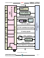
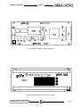
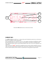
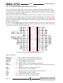
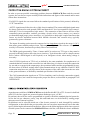
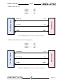
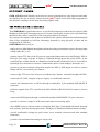
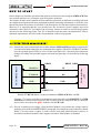
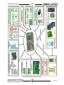
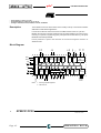
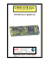
grifo®
ITALIAN TECHNOLOGY
LD1
DSW1
CN1
LD2
FIGURE 8: LEDS, DIP SWITCH, CONNECTOR LOCATION
CONNECTIONS
The GMM ACB Zero module has 1 connector that can be linkeded to other devices or directly to
the field, according to system requirements.
In this paragraph there are connector pin out, a short signals description (including the signals
direction) and connectors location (see figure 8) that simplify and speed the installation phase.
Some additional figures shows the pins functionalities and some of the most frequently used
connections.
All the connectors of grifo® cards follows standard pin outs in order to obtain a modular electronics
where each cards can be changed with many others, of the same or different type. This reduces times
and costs when modules become obsolete or insufficient for the application requirements.
GMM ACB Zero Rel. 5.00
Page 15