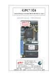
1
GMM 932
grifo® Mini Module P89LPC932
TECHNICAL MANUAL
Via dell' Artigiano, 8/6
® 40016 San Giorgio di Piano
(Bologna) ITALY
ITALIAN TECHNOLOGY
E-mail: [email protected]
http://www.grifo.it
http://www.grifo.com
Tel. +39 051 892.052 (a.r.) FAX: +39 051 893.661
grifo
GMM 932
Rel. 5.10
Edition 15 October 2004
®
®
, GPC , grifo , are trade marks of grifo®
GMM 932
grifo® Mini Module P89LPC932
TECHNICAL MANUAL
Standard container with 28 pins male socket, dual in line, 100 mils pitch,
600 mils width. Very small dimension: 20,7 x 38,7 x 12,8 mm. 4 layers
printed circuit to obtain best noisy resistance and best EMI performance.
Single power supply voltage required in the wide range from 3,0 to 20 Vdc,
25mA max. (the current consumption can change according with module
connections). Availability of power saving setting as idle mode, power
down mode and clock reduction. Philips P89LPC932 microcontroller
(8051 code compatibile) without crystal ( internal frequency of 7.3728
MHz ±2.5%) or with external 11.0592 Mhz crystal, by ordering option
.11MHZ. High performances thanks to 2 clocks machine cycle (6x). 8
KBytes FLASH for code, 768 Bytes RAM for data, 512 Bytes EEPROM
for data. 2 Analog Comparators channels with different input and output
configurations options. 15 Interrupt sources with 4 priority levels. 2
multifunctions Timers Counters, up to 16 bits. 4 CCU channels up to 16
bits with PWM, compare, capture, etc. functionalities. Up to 23 digital
I/O lines available on connector. Some of these lines have multiple
functions. Keypad interface that recognizes software presetted
combinations, on 8 of the 23 I/O lines, capable to generate interrupt. 1
Hardware serial communication line with programmable physical protocol
(Baud Rate up to 115200 Baud, 8 or 9 data bits, 1 or 2 stop bit), RS 232
buffered or at TTL level. Serial line supports automatic address recognition
and errors detection that simplify network connection of different units.
I2C BUS controller, completely software configurable. SPI interface
programmable for syncronous, high speed communications. One Real
Time Clock for long and accurate timing, active even in low power modes.
Watch Dog section that protect the controlled system in any operating
condition. 1 status LED tmanaged by software through one digital I/O line.
One 8 ways Dip switch for operating modes selection of the Mini Module.
Via dell' Artigiano, 8/6
® 40016 San Giorgio di Piano
(Bologna) ITALY
ITALIAN TECHNOLOGY
E-mail: [email protected]
http://www.grifo.it
http://www.grifo.com
Tel. +39 051 892.052 (a.r.) FAX: +39 051 893.661
grifo
GMM 932
Rel. 5.10
Edition 15 October 2004
®
®
, GPC , grifo , are trade marks of grifo®
DOCUMENTATION COPYRIGHT BY grifo® , ALL RIGHTS RESERVED
No part of this document may be reproduced, transmitted, transcribed, stored in a
retrieval system, or translated into any language or computer language, in any form or
by any means, either electronic, mechanical, magnetic, optical, chemical, manual, or
otherwise, without the prior written consent of grifo®.
IMPORTANT
Although all the information contained herein have been carefully verified, grifo®
assumes no responsability for errors that might appear in this document, or for damage
to things or persons resulting from technical errors, omission and improper use of this
manual and of the related software and hardware.
grifo® reserves the right to change the contents and form of this document, as well as
the features and specification of its products at any time, without prior notice, to obtain
always the best product.
For specific informations on the components mounted on the card, please refer to the
Data Book of the builder or second sources.
SYMBOLS DESCRIPTION
In the manual could appear the following symbols:
Attention: Generic danger
Attention: High voltage
Attention: ESD sensitive device
Trade Marks
, GPC®, grifo® : are trade marks of grifo®.
Other Product and Company names listed, are trade marks of their respective companies.
grifo®
ITALIAN TECHNOLOGY
GENERAL INDEX
INTRODUCTION ........................................................................................................................ 1
CARD VERSION ......................................................................................................................... 3
GENERAL INFORMATION ...................................................................................................... 4
DIGITAL I/O LINES ............................................................................................................... 6
SERIAL COMMUNICATION ............................................................................................... 6
CLOCK ..................................................................................................................................... 6
MEMORY DEVICES .............................................................................................................. 8
POWER SUPPLY SECTION ................................................................................................. 8
DIP SWITCH ........................................................................................................................... 8
TECHNICAL FEATURES ........................................................................................................ 10
GENERAL FEATURES ........................................................................................................ 10
PHYSICAL FEATURES ....................................................................................................... 10
ELECTRIC FEATURES....................................................................................................... 11
INSTALLATION ........................................................................................................................ 12
VISUAL SIGNALATIONS ................................................................................................... 12
CONNECTIONS .................................................................................................................... 12
CN1 - EXTERNAL POWER SUPPLY CONNECTOR................................................. 12
CONNECTOR SIGNALS INTERFACEMENT ................................................................. 14
INTERRUPTS ........................................................................................................................ 14
JUMPERS AND DIP SWITCH ............................................................................................ 16
SOLDER JUMPERS ............................................................................................................. 18
POWER SUPPLY .................................................................................................................. 18
CONFIGURTATION FOR SUPPORT CARDS ................................................................. 19
USE WITH GMB HR84 MODULE ................................................................................ 19
USE WITH GMM TST2 MODULE................................................................................ 21
HOW TO START ....................................................................................................................... 24
OPERATING MODE SELECTION .................................................................................... 34
ANALOG INPUTS ................................................................................................................ 34
SERIAL COMMUNICATION SELECTION ..................................................................... 34
DEVELOPMENT SOFTWARE ............................................................................................... 36
PERIPHERAL DEVICES SOFTWARE DESCRIPTION ..................................................... 38
STATUS LED ......................................................................................................................... 38
CPU INTERNAL PERIPHERALS ...................................................................................... 38
EXTERNAL CARDS ................................................................................................................. 39
BIBLIOGRAPHY ....................................................................................................................... 42
GMM 932
Rel. 5.10
Page I
grifo®
ITALIAN TECHNOLOGY
APPENDIX A: DATA SHEET ................................................................................................. A-1
P89LPC92 ............................................................................................................................... A-1
APPENDIX B: GMM TST2 ELECTRIC DIAGRAM ......................................................... B-1
APPENDIX C: ALPHABETICAL INDEX ............................................................................ C-1
Page II
GMM 932
Rel. 5.10
grifo®
ITALIAN TECHNOLOGY
FIGURES INDEX
FIGURE 1: LOCATION OF REVISION NUMBER AND CARD NAME ............................................................. 3
FIGURE 2: BLOCKS DIAGRAM ............................................................................................................ 7
FIGURE 3: GMM 932 PHOTO .......................................................................................................... 9
FIGURE 4: GMM 932.11MHZ PHOTO ............................................................................................. 9
FIGURE 5: GMM 932 PHOTO, BOTTOM VIEW ................................................................................. 11
FIGURE 6: LEDS TABLE ................................................................................................................. 12
FIGURE 7: CN1 - SOCKET WITH MINI MODULE SIGNALS ................................................................ 13
FIGURE 8: COMPONENTS MAP (COMPONENT SIDE) ........................................................................... 15
FIGURE 9: COMPONENTS MAP (SOLDER SIDE) .................................................................................. 15
FIGURE 10: JUMPER AND DIP SWITCH TABLE (PART 1) .................................................................... 16
FIGURE 11: JUMPER AND DIP SWITCH TABLE (PART 2) .................................................................... 17
FIGURE 12: LED, JUMPER, DIP SWITCH ETC. LOCATION ................................................................. 17
FIGURE 13: MINI BLOCK GMB HR 84 IN ITS CONTAINER CLOSED .................................................. 19
FIGURE 14: GMB HR 84 + GMM 932.11MHZ PHOTO ............................................................... 20
FIGURE 15: GMM TST2 + GMM 932 PHOTO ............................................................................. 21
FIGURE 16: GMM TST 2 + GMM 932.11MHZ PHOTO ............................................................... 23
FIGURE 17: RS 232 SERIAL CONNECTION BETWEEN A GMM 932 AND A PC ................................... 24
FIGURE 18: EXAMPLES TABLE ......................................................................................................... 25
FIGURE 19: FLASH MAGIC SETTING WINDOW (1 OF 4) .............................................................. 26
FIGURE 20: FLASH MAGIC SETTING WINNDOW (2 OF 4) ............................................................ 27
FIGURE 21: FLASH MAGIC SETTING WINDOW (3 OF 4) .............................................................. 27
FIGURE 22: FLASH MAGIC SETTING WINDOW (4 OF 4) .............................................................. 28
FIGURE 23: LOADING A SOURCE FILE WITH BASCOM 8051 .......................................................... 29
FIGURE 24: CONFIGURATION OF COMPILER BASCOM 8051 ......................................................... 29
FIGURE 25: COMPILATION WITH BASCOM 8051 ......................................................................... 30
FIGURE 26: LOADING SOUCE FILE WITH µC/51 ............................................................................... 30
FIGURE 27: LOADING MAKEFILE (COMPILING CONFIGURATION) WITH µC/51 ................................. 31
FIGURE 28: COMPILATION USING µC/51 ......................................................................................... 31
FIGURE 29: LOADING SOURCE SCHEMATIC WITH LADDER WORK ............................................. 32
FIGURE 30: COMPILER CONFIGURATION FOR LADDER WORK ................................................... 32
FIGURE 31: COMPILATION WITH LADDER WORK ..................................................................... 33
FIGURE 32: RS 232 SERIAL CONNECTION EXAMPLE ......................................................................... 35
FIGURE 33: TTL SERIAL CONNECTION EXAMPLE ............................................................................. 35
FIGURE 34: GMM 932 TOP VIEW PHOTO ....................................................................................... 37
FIGURE 35: GMM 932.11MHZ TOP VIEW PHOTO .......................................................................... 37
FIGURE 36: AVAILABLE CONNECTIONS DIAGRAM ............................................................................. 41
FIGURE B-1: GMM TST2 ELECTRIC DIAGRAM (1 OF 3) .............................................................. B-1
FIGURE B-2: GMM TST2 ELECTRIC DIAGRAM (2 OF 3) .............................................................. B-2
FIGURE B-3: GMM TST2 ELECTRIC DIAGRAM (3 OF 3) .............................................................. B-3
GMM 932
Rel. 5.10
Page III
grifo®
Page IV
ITALIAN TECHNOLOGY
GMM 932
Rel. 5.10
ITALIAN TECHNOLOGY
grifo®
INTRODUCTION
The use of these devices has turned - IN EXCLUSIVE WAY - to specialized personnel.
This device is not a safe component as defined in directive 98-37/CE.
Pins of Mini Module are not provided with any kind of ESD protection. They are connected directly
to their respective pins of microcontroller. Mini Module is affected by electrostatic discharges.
Personnel who handles Mini Modules is invited to take all necessary precautions to avoid possible
damages caused by electrostatic discharges.
The purpose of this handbook is to give the necessary information to the cognizant and sure use of
the products. They are the result of a continual and systematic elaboration of data and technical tests
saved and validated from the manufacturer, related to the inside modes of certainty and quality of
the information.
The reported data are destined- IN EXCLUSIVE WAY- to specialized users, that can interact with
the devices in safety conditions for the persons, for the machine and for the enviroment, impersonating
an elementary diagnostic of breakdowns and of malfunction conditions by performing simple
functional verify operations , in the height respect of the actual safety and health norms.
The informations for the installation, the assemblage, the dismantlement, the handling, the adjustment,
the reparation and the contingent accessories, devices etc. installation are destined - and then
executable - always and in exclusive way from specialized warned and educated personnel, or
directly from the TECHNICAL AUTHORIZED ASSISTANCE, in the height respect of the
manufacturer recommendations and the actual safety and health norms.
The devices can't be used outside a box. The user must always insert the cards in a container that
rispect the actual safety normative. The protection of this container is not threshold to the only
atmospheric agents, but specially to mechanic, electric, magnetic, etc. ones.
To be on good terms with the products, is necessary guarantee legibility and conservation of the
manual, also for future references. In case of deterioration or more easily for technical updates,
consult the AUTHORIZED TECHNICAL ASSISTANCE directly.
GMM 932
Rel. 5.10
Page 1
grifo®
ITALIAN TECHNOLOGY
To prevent problems during card utilization, it is a good practice to read carefully all the informations
of this manual. After this reading, the user can use the general index and the alphabetical index,
respectly at the begining and at the end of the manual, to find information in a faster and more easy
way.
Page 2
GMM 932
Rel. 5.10
grifo®
ITALIAN TECHNOLOGY
CARD VERSION
This handbook make reference to card GMM 932 with printed circuit version 300803. The validity
of the information contained in this manual is subordinated to the card version number.
PRINTED CIRCUIT REVISION NUMBER
FIGURE 1: LOCATION OF REVISION NUMBER AND CARD NAME
GMM 932
Rel. 5.10
Page 3
grifo®
ITALIAN TECHNOLOGY
GENERAL INFORMATION
GMM 932 (grifo® Mini Module 932) is a module based on microcontroller Philips P89LPC932,
a powerful and complete system on a chip provided with CPU (software compatible with famous
8051 INTEL), integrated memory (both for data and code), and a rich list of hardware peripheral
devices. Among these devices we can remind a watch dog, many digital I/O lines, an hardware serial
line, up to 6 multifunction timers counters with capture and compare capability, two synchronous
serial communication lines that follows SPI and I2C BUS standard protocols, 2comparators for
analog signals, a Real Time Clock for long time, etc.
In module's very small area, are already mounted the components that exploit microcontrollers's
performance and that allow each functionality mode; in addition to this, components that complete
and increase card's application fields are installed, like an efficient wide range power supply section.
Possible applications of GMM 932 Mini Modules are several. For example, smart Intelligent Nodes
with local functionalities as PID algorithms for controlling temperatures, motors, valves, etc. or
decentralized systems as robots, automation of production line machines, big factory automations.
Moreover Teleacquisition and Telecontrol on medium and low distances, the Home Automations
(lights turning ON/OFF, heating and cooling systems control, supervision of electric devices,
security and acces control systems), car automations (lights turning ON/OFF, heating and cooling
systems control, supervision services for drivers, anti-teft and acces control systems, functionality
checks).
It is really important the Didactics use in fact GMM 932 offers a very low cost system suitable to
learn microcontroller with 51 core and to develop the typical start applications for the students. For
this purpose it is likewise interesting the GMM TST 2 support card that solves the problems for
power supply, for serial connection to development P.C. and for module lines connection. In the same
support card there is a matrix keyboard and a LCD display that allow test and experience with low
cost user interface solutions.
The card use is simplified by a wide range of software developement tools based either on low or high
level languages which allow to work at the best conditions using only a standard PC. Noteworthy
among these tools there are the C, FORTH, BASIC compilers and a graphic programming
environment based on logic contact (LADDER). Special care has been devoted to the application
developing, by selecting programs which allow remote debug directly on the card and on board
FLASH burning with user application program, with the simple use of a standard P.C.
The GMM 932 is equipped with a normalized standard connector that allows immediate mounting
on support cards as GMM TST 2 and GMB HR84 or mounted directly on the board developed by
the user, as a macro component. Both the solutions ensure a short time to market: the user can obtain
a prototype or even a ready product in one week.
Overall features are:
- Standard container with 28 pins male socket, dual in line, 100 mils pitch, 600 mils width.
- Very small dimension: 20,7 x 38,7 x 12,8 mm.
- 4 layers printed circuit to obtain best noisy resistance and best EMI performance.
- Single power supply voltage required in the wide range from 3,0 to 20 Vdc, 25mA max.
(the current consumption can change according with module connections).
- Availability of power saving setting as idle mode, power down mode and clock
reduction.
- Philips P89LPC932 microcontroller (8051 code compatibile) without crystal ( internal
frequency of 7.3728 MHz ±2.5%) or with external 11.0592 Mhz crystal, by ordering
option .11MHZ.
- High performances thanks to 2 clocks machine cycle (6x).
Page 4
GMM 932
Rel. 5.10
ITALIAN TECHNOLOGY
grifo®
- 8 KBytes FLASH for code, 768 Bytes RAM for data, 512 Bytes EEPROM for data.
- 2 analog Comparators channels with different input and output configurations options.
- 15 interrupt sources with 4 priority levels.
- 2 multifunctions Timers Counters, up to 16 bits.
- 4 CCU channels up to 16 bits with PWM, compare, capture, etc. functionalities.
- Up to 23 digital I/O lines available on connector. Some of these lines have multiple
functions.
- Keypad interface that recognizes software presetted combinations, on 8 of the 23 I/O
lines, capable to generate interrupt.
- Hardware serial communication line with programmable physical protocol (Baud
Rate up to 115200 Baud, 8 or 9 data bits, 1 or 2 stop bit), RS 232 buffered or at TTL level.
- Serial line supports automatic address recognition and errors detection that simplify
network connection of different units.
- I2C BUS controller, completely software configurable.
- SPI interface programmable for syncronous, high speed communications.
- One Real Time Clock for long and accurate timing, active even in low power modes.
- Watch Dog section that protect the controlled system in any operating condition.
- 1 status LED tmanaged by software through one digital I/O line.
- One 8 ways Dip switch for operating modes selection of the Mini Module.
- Internal FLASH can be managed through ISP (In System Programming), or when the
module is already mounted, by using the serial communication line.
- No external programmer is needed in fact, as all the grifo® Mini Module, the FLASH
of microcontroller is Erased, Programmed, Verified, Protected by using only the serial
line of a standard Personal Computer.
- For FLASH management on P.C. it is used the freeware Flash Magic program available
from Esacademy.
- Wide range of software development tools used to develop the user application
program, as: Assembler (MCA51); C compilers (µC/51, HTC51, SYS51CW, DDS
Micro C51); BASIC compilers (BASCOM 8051); PASCAL compilers (SYS51PW);
contacts logic (LADDER WORK); etc.
- Long list of demo programs and use examples supplied under source form, duly
remarked, and executable form for the available development tools.
Here follows a description of the board's functional blocks, with an indication of the operations
performed by each one. To easily locate such section on verify their connections please refer to figure
2.
GMM 932
Rel. 5.10
Page 5
grifo®
ITALIAN TECHNOLOGY
DIGITAL I/O LINES
The Mini Module GMM 932 is provided with 23 digital I/O lines at TTL level, of the microprocessor
Philips P89LPC932, that are all the signals of Ports 0, 1, 2 except P1.6.
These lines are connected directly to 28 pins connectors with standard grifo® Mini Module pin out,
allowing to be connected direclty to several interface cards.
By software it is possible to define and acquire the function and the status of these lines, and also to
match them to peripheral devices (like Timer Counter, Interrupt, I2C BUS, SPI, etc.), simply
programming some CPU internal registers.
For further information please refer to paragraph CONNECTIONS and PERIPHERAL DEVICES
SOFTWARE DESCRIPTION.
SERIAL COMMUNICATION
On GMM 932 it is always available an hardware serial line that is completely software configurable
for physical protocol (baud rate, stop bits number, lenght of character, etc) by simply programming
some microprocessor registers as described in the manufacturer documentation or in the appendix
of this manual.
The serial line is connected to CN1 connector at TTL or RS 232 level, thanks to some on board dip
switches configuration, so when the card must be connected in a network or at long distance or with
other systems that use different electric protocol, the user must provide external drivers (RS 232,
RS 422, RS 485, Current loop, etc.). Please remember that on CN1 connector more than standard
receive and transmit signals are available also other I/O signals that can be driven by software; these
signals can be used to define the RS 485 line direction, to enable the RS 422 transmit drive or to
generate an RS 232 handshake. For example it can be used the MSI 01 module that converts a TTL
serial line in any other electric standards in a pratical and inexpensive way.
Please read SERIAL COMMUNICATION SELECTION paragraph of this manual or contact
directly grifo® technician for further explanation or any other necessary information.
CLOCK
On GMM 932 module there are two separate and indipendent circuits based on RC oscillator and
crystal, that generate the clock signal for the microcontroller. The first generates a 7.3728 MHz
±2.5% and it is always available while the second generates a 11.0592 MHz and it is available only
when .11MHz option is ordered.
The choice of using two circuits and two separated clock sources, has the advantage to reduce cost
in the larger number of low, middle spped applications and to afford the high speed applications when
necessary.
About speed and performances please remind that GMM 932 has a 2 clocks machine cycle and when
compared with traditional I51 CPUs, it execute the code 6 times faster.
Page 6
GMM 932
Rel. 5.10
grifo®
6 Lines
LED
2 Lines
2 Lines
4 Lines
20 signals
2 signals
(TTL serial line)
2 Lines
RS 232 DRIVER
protection ±15 kV
8 Lines
23 Lines
28 pins socket CN1
2 Lines
1 signals
Internal MUX
7 Lines
CPU
P89LPC932
WORKING MODE
SELECTOR
(RUN/DEBUG)
WIDE RANGE
POWER SUPPLY
SECTION
2.6 ÷ 20 Vdc
CLK
ANALOG
512 B
768 B 8 KB RTC WATCH PORT KEYPAD UART SPI INT I2C PWM, TIMER
CCU
EEPROM RAM FLASH
COUNTER COMPARATOR
DOG
I/O
ITALIAN TECHNOLOGY
FIGURE 2: BLOCKS DIAGRAM
GMM 932
Rel. 5.10
Page 7
grifo®
ITALIAN TECHNOLOGY
MEMORY DEVICES
The card is provided of 9.25K of memory divided with a maximum of 8K Bytes FLASH EPROM,
256 Bytes of internal IRAM, 512 Bytes of auxiliary external XRAM and 512 Bytes EEPROM.
The memory configuration must be chosen considering the application to realize or the specific
requirements of the user.
Thanks to on board EEPROM there is the possibility to keep data also when power supply is failed;
in this way the card is always able to maintain parameters, logged data, system status and
configuration, etc. in each working conditions.
Whenever the amount of memory for data is not sufficient (i.e. for data loghin systems), it is always
possible to connect external memory devices (with SRAM, EEPROM, FLASH technologies)
through the comfortable and efficient SPI and I2C BUS interface of the card.
The addressing of memory devices is controlled by microcontroller as described in the component
data sheet or in APPENDIX A of this manual.
POWER SUPPLY SECTION
On GMM 932 module is always mounted an efficient linear power supply section, that provides the
necessary +3.3 Vdc supply voltage in each condition of load and input voltage.
If required, the power supply section can be bypassed and an external source must provide the
described supply voltage, while in the base configuration a wide range input supply voltage is
accepted, up to +20 Vdc.
This feature allow the use of all the voltages already available in the application, without additional
costs and complications of external power supplies.
Moreover the power supply section can be driven by a specific signal connected to CN1, that can
enable the internal Boot Loader by software.
Thus, by using a simple Personal Computer, it is possible to develop the application program; in fact
the P.C. connected to the described signal controls the GMM 932 power supply and it can select the
necessary operating modes.
On the board all the circuits and components have been chosen to obtain the best noisy immunity and
the lowest consumption, including the possibility to use four different power down setting of the
microcontroller.
In the best conditions a minimum consumtion of 7 mA is reached and it is suitable for portable
applications where battery life time is increased.
Detailed information are reported in ELECTRIC FEATURES chapter and in POWER SUPPLY
paragraph.
DIP SWITCH
GMM 932 Mini Module is provided with an on board dip switch whose purpose is to set up several
electric parameters of module itself and the card operating mode.
In fact some switches selects the RUN or DEBUG operating mode that determine whether the
microcontroller has to run the user application program or the internal Boot Loader, as described in
proper paragraph OPERATING MODE SELECTION.
For further information please see also the paragraph JUMPER AND DIP SWITCH.
Page 8
GMM 932
Rel. 5.10
ITALIAN TECHNOLOGY
grifo®
FIGURE 3: GMM 932 PHOTO
FIGURE 4: GMM 932.11MHZ PHOTO
GMM 932
Rel. 5.10
Page 9
grifo®
ITALIAN TECHNOLOGY
TECHNICAL FEATURES
GENERAL FEATURES
Resources:
23 digital I/O lines
2 analog inputs on comparators
4 CCU cnannels for compare, capture, PWM
1 Watch dog section
2 multifunction Timer Counter
1 KBI interface for combinations recognition
1 SPI interface
1 I2C BUS interface
1 Real Time Clock section
15 interrupt sources with 4 level priority
1 hardware serial line RS 232 or TTL
1 Dip switch, 8 ways
1 status LED
Memories:
8 KBytes FLASH EPROM for code
256 Bytes IRAM for data
512 Bytes XRAM for data
512 Bytes EEPROM for data
CPU:
Philips P89LPC932
Clock frequency:
7.3728 MHz ±2,5%
11.0592 MHz
Power on time:
800 µsec max
Watch dog intervent time:
programmable up to 2.5 sec
(.11MHz option)
PHYSICAL FEATURES
Size: (W x H x D):
20.7 x 38.7 x 12.8 mm
Weight:
6.9 g
Connectors:
28 pins male socket DIL, 100 mils pitch, 600 mils width
Temperature range:
0÷50 °C
Relative humidity:
20%÷90%
Page 10
(without condense)
GMM 932
Rel. 5.10
grifo®
ITALIAN TECHNOLOGY
ELECTRIC FEATURES
Power supply voltage:
+3,6÷+20,0 Vdc
+3,0÷ +3,6 Vdc
+2,6÷ +3,6 Vdc
Current consumption:
minimum:
normal:
maximum:
Base version
7 mA
17 mA
21 mA
I/O lines voltage:
0.0÷5.0 V
Analog inputs impedance:
≈ 300 KΩ
(with power supply section)
(without power supply section)
(without power supply section and RS 232)
.11MHz option
7 mA
21 mA
25 mA
FIGURE 5: GMM 932 PHOTO, BOTTOM VIEW
GMM 932
Rel. 5.10
Page 11
grifo®
ITALIAN TECHNOLOGY
INSTALLATION
In this chapter there are the information for a right installation and correct use of the GMM 932 card.
In detail there are the locations and functions of each connector, of the user settable jumper and dip
switches, of the LED, and so on.
VISUAL SIGNALATIONS
GMM 932 features the LED described in the following table:
LED
COLOUR
FUNCTION
DL1
Red
It shows status of KBI6 , CMPI , P0.6 line of the mini module and
it can be used as activity LED, driven by software.
FIGURE 6: LEDS TABLE
The main function of this LED is to inform the user about card status, with a simple visual indication
and in addition to this, LEDs make easier the debug and test operations of the complete system. To
recognize the LED location on the card, please refer to figure 12. while for further information please
refer to paragraph ACTIVITY LED.
CONNECTIONS
The GMM 932 module has 1 connector that can be linkeded to other devices or directly to the field,
according to system requirements.
In this paragraph there are connector pin out, a short signals description (including the signals
direction) and connectors location (see figure 12) that simplify and speed the installation phase.
Some additional figures shows the pins functionalities and some of the most frequently used
connections.
CN1 - EXTERNAL POWER SUPPLY CONNECTOR
CN1 is a 28 pins, male, dual in line, socket connector with 100 mils pitch and 600 mils width.
On CN1 are available all the interfacement signals of the Mini Module as the power supply, the
I/O lines, the synchronous and asynchronous communication lines, the on board peripheral devices
signals, the operating mode selection lines, etc.
Some pins of this connector have multiple purposes, in fact they can be multiplexed by programming
some software registers with several CPU internal devices and the following figure lists all these
possible functionalities. So the signals available on CN1 have different types as described in the
following CONNECTOR SIGNALS INTERFACEMENT paragraph and they follow grifo® Mini
Module standard pin out.
Page 12
GMM 932
Rel. 5.10
grifo®
ITALIAN TECHNOLOGY
To avoid problems in pin counting and numbers the figure 7 shows the signals directly on the top view
of the GMM 932; moreover the serigraph reports the pins number on the four corner of the card both
on bottom (solder) and top (component) side.
BOOT (RTS)
POW (DTR)
RX RS232 , RX TTL , P1.1
TX RS232 , TX TTL , P1.0
N.C.
SCL , T0 , P1.2
SDA , /INT0 , P1.3
MOSI , P2.2
MISO , P2.3
KBI6 , CMP1 , P0.6
ICB , P2.0
SPICLK , P2.5
KBI7 , T1 , P0.7
GND
1
2
3
4
5
6
7
8
9
10
11
12
13
14
28
27
26
25
24
23
22
21
20
19
18
17
16
15
+Vdc POW
P2.4 , /SS
P0.0 , CMP2 , KBI0
P0.1 , CIN2B , KBI1
P2.6 , OCA
P1.6 , OCB
P1.7 , OCC
P2.1 , OCD
P2.7 , ICA
P0.2 , CIN2A , KBI2
P1.4 , /INT1
P0.3 , CIN1B , KBI3
P0.4 , CIN1A , KBI4
P0.5 , CMPREF , KBI5
FIGURE 7: CN1 - SOCKET WITH MINI MODULE SIGNALS
Signals description:
BOOT (RTS)
POW (DTR)
RX RS232
TX RS232
RX TTL
TX TTL
Pn.x
SCL
SDA
Tn
/INTn
MOSI
MISO
/SS
SPICLK
KBIn
CMPn
CINnA
CINnB
CMPREF
ICA
OCn
+Vdc POW
GND
N.C.
GMM 932
= I - Operating mode selection signal, it must be connected to RTS signal
buffered in RS 232, of development P.C.
= I - CPU power supply management signal, it must be connected to DTR signal
buffered in RS 232, of development P.C.
= I - Serial receive data, buffered in RS 232
= O - Serial transmit data, buffered in RS 232
= I - Serial receive data, at TTL level
= O - Serial transmit data, at TTL level
= I/O - Microcontroller I/O digital signal x of Port n
= I/O - Clock signal of I2C BUS interface
= I/O - Data signal of I2C BUS interface
= I - Counting signal for Timer n of microcontroller
= I - Interrupt line n of microcontroller
= I/O - Output data signal of SPI interface
= I/O - Intput data signal of SPI interface
= I - Slave unit select signal of SPI interface
= I/O - Clock signal of SPI interface
= I - Keyboard digital input n for combinations recognition
= O - Analog comparator n output signal
= I - First positive input signal of analog comparator n
= I - Second positive input signal of analog comparator n
= I - Negative input signal of analog comparators
= I - Capture and compare input signal for CCU section
= O - Compare output signal n of CCU section
= I - Power supply line, from +2,6 to +20,0 Vdc (see POWER SUPPLY)
=
- Ground line
=
- Not connected
Rel. 5.10
Page 13
grifo®
ITALIAN TECHNOLOGY
CONNECTOR SIGNALS INTERFACEMENT
To prevent possible connecting problems between GMM 932 and the external systems, the user has
to read carefully the previous paragraph information and he must follow these instrunctions:
- For RS 232 signals the user must follow the standard specifications of this protocol, defined by
CCITT normative;
- All TTL signals must follow the rules of this electric standard. The connected digital signals must
be always referred to card ground (GND) and then the 0V level corresponds to logic state 0, while
the 3÷5V level corrisponds to logic state 1. The connection of these lines to devices of the controlled
system (encoders, switches, proximity, electric valves, power relays, etc.) must be performed
through proper power interfaces; it is preferible to adopt opto coupled interfaces that ensure an
electric insulation between Mini Module electronic and external noisy, typically generated by
power electronic.
- The inputs for analog comparators must be connected to low impedance signals in the range from
0 to 3,0 V, to assure greater stability and precision.
- PWM signals generated by Timer Counter and CCU sections are TTL type so they must be buffered
to interface the power circuitery. Typical interfaces can be current driver (if PWM signal is still
required) or an intergrator circuit if analog voltage is required.
- Also I2C BUS and SPI signals are at TTL level, as defined by the same standards; for completeness
it is remarked that in a network with several devices and rather long it is better to study the
connection lay out and to set properly the output stage, the best operational modes and the
programmable bit rate: all these conditions allow communications in any condition.
INTERRUPTS
A remarkable feature of GMM 932 card is the powerful interrupt management. Here follows a short
description of which devices can geneate interrupts and their modalities; for further information
about interrputs management please refer to the micro data sheet or APPENDIX A of this manual.
- Pin 7 of CN1 ->
- Pin 18 of CN1 ->
- CPU peripherals ->
Generates an interrupt on /INT0 = P1.3 of microprocessor.
Generates an interrupt on /INT1 = P1.4 of microprocessor.
Generate an internal interrupt. In detail the possible microcontroller
interrupt sources are: Timer Counter, CCU, UART, analog
comparators, Watch dog, Real Time Clock, I2C BUS, SPI, Keyboard
interface, EEPROM.
An interrupt management section, integrated in microcontroller, allows to enable, disable, mask and
prioritize , so the user has the possibility to respond promptly and efficently to any external event.
The microcontroller has an interrupt section that let the user manage the 15 interrupt sources; the
addresses of the interrupt service routines can be software programmed by the user placing them on
the proper code areas while the interrupts priority level and activation are sofware programmable
through internal CPU registers. So theapplication program has always the possibility to react
promptly to every event, deciding also the priority of contemporary interrupts.
Page 14
GMM 932
Rel. 5.10
grifo®
ITALIAN TECHNOLOGY
FIGURE 8: COMPONENTS MAP (COMPONENT SIDE)
FIGURE 9: COMPONENTS MAP (SOLDER SIDE)
GMM 932
Rel. 5.10
Page 15
grifo®
ITALIAN TECHNOLOGY
JUMPERS AND DIP SWITCH
On GMM 932 module there are an 8 ways dip switch and a jumper that defines some configurations
of the card. In the following figures is reported their list, their position and their functions in all the
available connection modes.
The * (asterisk) denotes the default connection, or on the other hand the connection set up at the end
of testing phase, that is the configuration the user receives.
To recognize the configuration elements location, please refer to figure 12.
SWITCH
JUMPER
POSITION
ON
DSW1.1
OFF
ON
DSW1.2
OFF
FUNCTION
DEF.
It connects the serial receice signal of the microcontroller to
RS232 driver. Used in conjunction with DSW1.3,5.
It doesn't connect the serial receice signal of the
microcontroller to RS232 driver, by allowing the direct
connection to RX RS232 , RX TTL , P1.1 signal on CN1.
Used in conjunction with DSW1.3,5.
It connects TX RS232 , TX TTL , P1.0 signal on CN1 to
RS232 serial driver. Used in conjunction with DSW1.4.
It doesn't connect TX RS232 , TX TTL , P1.0 signal on CN1
to RS232 serial driver by allowing the direct connection to
microcontroller. Used in conjunction with DSW1.4.
ON
It connects RX RS232 , RX TTL , P1.1 signal on CN1 to
RS232 serial driver. Used in conjunction with DSW1.1,5.
OFF
It doesn't connect RX RS232 , RX TTL , P1.1 signal on CN1
to RS232 serial driver by allowing the direct connection to
microcontroller. Used in conjunction with DSW1.1,5.
DSW1.3
ON
DSW1.4
OFF
ON
DSW1.5
OFF
It connects TX RS232 , TX TTL , P1.0 signal on CN1
directly to microcontroller, with no use of RS232 serial
driver. Used in conjunction with DSW1.2.
It doesn't connect TX RS232 , TX TTL , P1.0 signal on CN1
to microcontroller, by allowing the use of RS232 serial
driver. Used in conjunction with DSW1.2.
It connects RX RS232 , RX TTL , P1.1 signal on CN1
directly to microcontroller, with no use of RS232 serial
driver. Used in conjunction with DSW1.1,3.
It doesn't connect RX RS232 , RX TTL , P1.1 signal on CN1
to microcontroller, by allowing the use of RS232 serial
driver. Used in conjunction with DSW1.1,3.
ON
It connects 3,3 Vdc power supply signal directly to pin 28
of CN1, with no use of the on board power supply section.
Used in conjunction with JS1.
OFF
It doesn't connect 3,3 Vdc power supply signal directly to
pin 28 of CN1.
DSW1.6
*
*
*
*
*
*
FIGURE 10: JUMPER AND DIP SWITCH TABLE (PART 1)
Page 16
GMM 932
Rel. 5.10
grifo®
ITALIAN TECHNOLOGY
SWITCH
JUMPER
POSITION
ON
DSW1.7
OFF
ON
DSW1.8
FUNCTION
DEF.
It connects Boot Loader activation circuit of the Mini
Module.
It doesn't connect Boot Loader activation circuit of the Mini
Module.
It mantains powered the Mini Module, with no management
trough POW line on CN1.
*
OFF
It doesn't mantain powered the Mini Module, and it enables
proper power supply management trough POW line on CN1.
Not connected
It doesn't connect 3,3 Vdc power supply signal directly to
pin 28 of CN1.
Connected
It connects 3,3 Vdc power supply signal directly to pin 28
of CN1, with no use of the on board power supply section.
Used in conjunction with DSW1.6.
JS1
*
*
FIGURE 11: JUMPER AND DIP SWITCH TABLE (PART 2)
DSW1
DL1
CN1
JS1
FIGURE 12: LED, JUMPER, DIP SWITCH ETC. LOCATION
GMM 932
Rel. 5.10
Page 17
grifo®
ITALIAN TECHNOLOGY
SOLDER JUMPERS
The default setting of the solder jumpers, named JSxx, is performed with a small track on the printed
circuit, so if this setting must be changed, first cut the possible default connection track with a sharp
cutter and then connect the required position with a low power solder and some non corrosive tin.
POWER SUPPLY
One of the most important features of GMM 932 is its on board circuit that resolves the problem of
power supply in each circumstance and with an efficient and comfortable manner.
The card has two different power supply configurations as below described:
power supply section connected:
JS1
=
Not connected
DSW1.6
=
OFF
+Vdc POW
=
+3,6 ÷ +20 Vdc
In this configuration the on board linear power supply section is used and it allows to connect
to Mini Module a wide range supply voltage that must be linked to pin 14 (GND) and 28 (+Vdc
POW) of CN1. All the standard industrial sources like laboratory feeders, batteries, solar
cells,veichle batteries, etc.
power supply section not connected:
JS1
=
Connected
DSW1.6
=
ON
+Vdc POW
=
+3,0 ÷ +3,6 Vdc (with RS 232 serial line)
+Vdc POW
=
+2,6 ÷ +3,6 Vdc (with TTL serial line)
In this configuration the on board linear power supply section is not used, so the Mini Module
requires a stabilized supply voltage that changes in the short ranges before described and that
must be connected to pin 14 (GND) and 28 (+Vdc POW) of CN1. In this condition, for examle,
it can be used the voltage produced by commercial batteries, by Lithium batteries, by external
stabilizers, by low voltage power supply section already mounted on the support card of
GMM 932, etc.
The power supply section configuration must be performed by the user according with his
requirements and voltage availability. However we remember that the configuration with power
supply section connected is the default version received by the user, in fact it ensures an higher
flexibility and an higher safety during the first use.
To reduce power consumption, microcontroller power down and clock reduction modes can be
employed. These modalities allow to reduce the CPU working frequency and to enable or disable the
internal peripherals by programming some specific internal registers of the same CPU. The user
application program can reduce supply consumption up to as low as 7 mA and eventually restore the
normal working mode when a specific event occours, like and interrupt, a variation on an analog or
digital input, a timeout, etc.
For further information please refer to paragraph ELECTRIC FEATURES.
Page 18
GMM 932
Rel. 5.10
ITALIAN TECHNOLOGY
grifo®
CONFIGURTATION FOR SUPPORT CARDS
The GMM 932 Mini Module can be used as a macro components for some support cards either
developed by the user or directly chosen from the grifo® boards. In the following paragraphs are
reported the suggested configuration of the most interesting support cards.
USE WITH GMB HR84 MODULE
Amongst grifo® cards, GMB HR84 module is the one designed specifically to provide to 28 pins
Mini Modules many interesting features as: 8 optocoupled inputs, 4 relay outputs, mechanical
mounting on omega rails and a comfortable wiring through screw terminal connectors. The complete
description of the product is available in the relative data sheet and technical manual while in this
paragraph are listed the advantages obtained by using this pair of cards:
FIGURE 13: MINI BLOCK GMB HR 84 IN ITS CONTAINER CLOSED
The GMB HR84 allows easily to:
- supply the Mini Module through on board wide range AC, DC power supply;
- have eight I/O signals of microcontroller ports optocoupled NPN and PNP at the same time and
visualized through green LEDs; I/O signals are multiplexed with internal peripheral devices, so
high level functions as couters, status recognition, etc.,are immediatly available;
- have other four I/O signals of microcontroller ports on bufferd relays and visualized through red
LEDs; I/O signals are multiplexed with internal peripheral devices, so high level functions like
sqare waves, time based signals, etc., are immediatly available;
- connect I2C BUS and +5 Vdc power supply on a dedicated connector;
GMM 932
Rel. 5.10
Page 19
grifo®
ITALIAN TECHNOLOGY
- connect immediately RS 232 serial line through a comfortable 9 pins D type connector;
- buffer easily the TTL serial line in RS 422, RS 485 or Current Loop;
- connect SPI line and PWM signals on AMP connector;
- program the FLASH in ISP modality.
FIGURE 14: GMB HR 84 + GMM 932.11MHZ PHOTO
The following configuration is suggested to use the couple GMB HR84 + GMM 932 in their base
version, that is RUN mode with serial line buffered in RS 232:
GMM 932 configuration
JS1
=
not connected
DSW1.1 =
ON
DSW1.2 =
ON
DSW1.3 =
ON
DSW1.4 =
OFF
DSW1.5 =
OFF
DSW1.6 =
OFF
DSW1.7 =
OFF
DSW1.8 =
ON
GMB HR84 configuration
J1 =
not connected
J2 =
2-3
J3 =
2-3
J4 =
2-3
J5 =
don't care
J6 =
1-2
J7 =
don't care
J8 =
not connected
J9 =
not connected
J10 =
1-2
J11 =
1-2
The serial connection cable with development P.C. is the CCR 9+9 R (or in other words an extension
reversed cable provided of D9 Female and D9 Male connectors).
Page 20
GMM 932
Rel. 5.10
grifo®
ITALIAN TECHNOLOGY
USE WITH GMM TST2 MODULE
Amongst grifo® cards, GMM TST2 is the one designed specifically to provide a first entry point to
28 and 40 pins Mini Modules, with suitable evaluation purposes. The complete description of the
product is available in the relative data sheet and technical manual while in this paragraph are listed
the advantages obtained by using this pair of cards:
FIGURE 15: GMM TST2 + GMM 932 PHOTO
GMM 932
Rel. 5.10
Page 21
grifo®
ITALIAN TECHNOLOGY
The GMM TST2 allows easily to:
- supply the Mini Module through on board AC, DC power supply;
- connect all the I/O signals of microcontroller ports on comfortable connectors compatible with
I/O ABACO® standard pin out;
- connect immediately RS 232 serial line through a comfortable 9 pins D type connector;
- set and show the status of 2 microcontroller I/O lines through push button and LEDs with different
colours;
- generate audible feed back thanks to active buzzer mounted on board;
- develop in a short time user interface applications by using the on board matrix keyboard with
4x4=16 keys and the backlite LCD display with 2 rows of 20 characters;
- develop easily a support card that satisfy customer requirements starting from the supplied electric
diagrams;
- program the FLASH in ISP modality.
The following configuration is suggested to use the couple GMM TST2 + GMM 932 in their base
version, that is RUN mode with serial line buffered in RS 232:
GMM 932 configuration
JS1
=
not connected
DSW1.1 =
ON
DSW1.2 =
ON
DSW1.3 =
ON
DSW1.4 =
OFF
DSW1.5 =
OFF
DSW1.6 =
OFF
DSW1.7 =
OFF
DSW1.8 =
ON
GMM TST2 configuration
J1 =
1-2
J2 =
2-3
J3 =
2-3
J4 =
2-3 or not connected
J5 =
2-3 or not connected
J6 =
2-3 or not connected
J7 =
2-3 or not connected
The serial connection cable with development P.C. is the CCR 9+9 E (or in other words an extension
cable provided of D9 Female and D9 Male connectors).
Page 22
GMM 932
Rel. 5.10
ITALIAN TECHNOLOGY
grifo®
FIGURE 16: GMM TST 2 + GMM 932.11MHZ PHOTO
GMM 932
Rel. 5.10
Page 23
grifo®
ITALIAN TECHNOLOGY
HOW TO START
Across this chapter we presume that you have a GMM TST 2 where to install GMM 932.
One of the most important features of GMM 932 Mini Module is the possibility to program the
microprocessor P89LPC932 internal memory with in system programming (ISP) through serial
interface.
A) SERIAL CONNECTION BETWEEN GMM 932 AND PC
A1) To make the serial connection between GMM 932 and a PC, the stricture described on
figure 17 should be built.
3
RX RS232
TX
2
3
4
TX RS232
RX
3
2
1
BOOT
RTS
4
7
2
POW
DTR
20
4
14
GND
GND
7
5
Connector to
P.C. COM serial line
CN1 GMM 932
DB25F DB9F
CN5 GMM TST 2 or
CN2 GMB HR84
FIGURE 17: RS 232 SERIAL CONNECTION BETWEEN A GMM 932 AND A PC
A2) Keep ready for running a terminal emulator on PC, configure it to use the serial port where
Mini Module is connected with 19200 baud, 8 data bits, 1 stop bit, no parity. If you are
using BASCOM 8051, you simply can open the terminal emulator in its IDE.
A3) Set Mini Module in DEBUG mode, that is DSW1.1 ON.
A4) Supply GMM TST 2 or GMB HR84. Find the demo programs of GMM 932 on grifo®
CD, one of the file is called "iod932uk.hex" and can be found from the starting follwing
the path: English | Examples Tables | Mini Block and Mini Modules programs | GMM
932.
Page 24
GMM 932
Rel. 5.10
ITALIAN TECHNOLOGY
grifo®
FIGURE 18: EXAMPLES TABLE
GMM 932
Rel. 5.10
Page 25
grifo®
ITALIAN TECHNOLOGY
B) FLASH REPROGRAMMING
B1) Find and save to a comfortable position on your hard drive the file "iod932uk.hex".
B2) On grifo® CD it is also available the utility program FLASH MAGIC. that manages the
ISP programming of microcontroller memories on board of GMM 932 through the
simple serial connection seen at point A; find it and install it on a comfortable position
on your hard drive. It is suggested to use version 2.07 or greater.
B3) Put switch 1 of DSW1.7 of GMM 932 in position ON and DSW1.8 in position OFF, to
set DEBUG mode.
B4) Close the terminal emulator, if open.
B5) Turn off and then turn on again GMM TST 2 or GMB HR84.
B6) Run ISP programming sofware installed at step B2.
B7) Inside windows 1 perform the following settings:
Com Port = COMx of development P.C., connected at point A1
Baud Rate = 9600
Device
= 89LPC932
B8) Select the option "Advanced options” from menu “Options” and in the displayed
window perform the following settings:
Hardware Config | Use DTR and RTS to enter ISP mode
Hardware Config | Hardware = Keil MCB 900
Security
| Protect ISP Code
and once confirmed the shown requests, check that the communication is established
with Boot Loader of the card.
FIGURE 19: FLASH MAGIC SETTING WINDOW (1 OF 4)
Page 26
GMM 932
Rel. 5.10
ITALIAN TECHNOLOGY
grifo®
FIGURE 20: FLASH MAGIC SETTING WINNDOW (2 OF 4)
B9) Inside windows 2 perform the following settings:
Erase all Flash
B10) Inside windows 3 load the file to program iod932uk.HEX, described at point B1.
B11) Inside windows 4 disable all the possible settings.
B12) Inside windows 5 begin the programmation by pressing the "Start" button, confirm (Yes)
the request of modified erase operation that protect the ISP code and verify that all the
following steps are correctly executed.
FIGURE 21: FLASH MAGIC SETTING WINDOW (3 OF 4)
GMM 932
Rel. 5.10
Page 27
grifo®
ITALIAN TECHNOLOGY
FIGURE 22: FLASH MAGIC SETTING WINDOW (4 OF 4)
B13) Exit from FLASH MAGIC by pressing the X in the high right corner of the window; thus
all the performed settings are saved and they must not be repeated in the next use.
B14) Run the teminal emulator HYPERTERMINAL configured as point A2, and check that
the application program just programmed is executed from the internal FLASH.
The HYPERTERMINAL settings and execution can be also obtained by a simple double
click on the icon of a specific configuration file (with extension .HT) that can be created
directly by HYPERTERMINAL, with the save option of the "File" menu.
C) GENERATING DEMO EXECUTABLE CODE
C1) Install on the hard disk of the development P.C. the software environment selected to
develop the application program. As described in the chapter SOFTWARE
DESCRIPTION there are many different software tools that satisfy any customers
requirements but here we remind only the most diffused as the BASCOM 8051, µC/51,
LADDER WORK, etc.
C2) On grifo® CD in addition to file with the executable code of the demo program, described
at point B1, there are also the source files of the same. These have an extension that
identifies the used software development tools (for example iod932uk.bas for BASCOM
8051 or iod932uk.c for µC/51) and they are properly organized inside demo programs
tables available on CD, together with possible definition file (89LPC932.DAT for
BASCOM 8051, 89LPC932.H for µC/51, etc.). Once these files have been located they
must be copied in a comfortable folder on the hard disk of development P.C.
C3) Compile the source file by using the selected software tools: the file iod932uk.hex must
be obtained equal to those available on grifo® CD and already used at points B. This
operation is very different according to the programming environment selected, so here
follow the details:
Page 28
GMM 932
Rel. 5.10
ITALIAN TECHNOLOGY
grifo®
I) Ricompilation using BASCOM 8051.
Ia) When in BASCOM IDE, load the program source with menu File | Open:
FIGURE 23: LOADING A SOURCE FILE WITH BASCOM 8051
Ib) From menu Options | Compiler | Misc set the value of Byte End to A0, as suggesterd
also in the source code, and press OK:
FIGURE 24: CONFIGURATION OF COMPILER BASCOM 8051
GMM 932
Rel. 5.10
Page 29
grifo®
ITALIAN TECHNOLOGY
Ic) Compile the source file by pressing the button with the icon of an integrated circuit.
Presence of file 89LPC932.DAT in BASCOM installation folder is required in order
to compile correctly:
FIGURE 25: COMPILATION WITH BASCOM 8051
II) Ricompilatione with µC/51.
IIa) After opening standard editor uedit.exe, load the source file pressing the fifth button
from the left, the presence of file canary.h in the same folder of file iod932uk.c is
required for a correct compilation:
FIGURE 26: LOADING SOUCE FILE WITH µC/51
IIb) Open also MakeFile editor, that is program umshell.exe, and load file iod932uk.mak
with the menu File | Load:
Page 30
GMM 932
Rel. 5.10
ITALIAN TECHNOLOGY
grifo®
FIGURE 27: LOADING MAKEFILE (COMPILING CONFIGURATION) WITH µC/51
IIc) Compile the source file pressing the first button from the right:
FIGURE 28: COMPILATION USING µC/51
GMM 932
Rel. 5.10
Page 31
grifo®
ITALIAN TECHNOLOGY
III) Ricompilation using LADDER WORK.
IIIa) After opening IDE of LADDER WORK, open the schematic file called iod932uk.pjn
with menu File | Open:
FIGURE 29: LOADING SOURCE SCHEMATIC WITH LADDER WORK
IIIb) Assure that the selected profile is the one specific for GMM 932:
FIGURE 30: COMPILER CONFIGURATION FOR LADDER WORK
Page 32
GMM 932
Rel. 5.10
grifo®
ITALIAN TECHNOLOGY
IIIc) Compile the source schematic pressing the first button from the right:
FIGURE 31: COMPILATION WITH LADDER WORK
C4) Reperform the programmation of the obtained HEX file in the Mini Module FLASH, by
executing again the points B6÷B14.
About the FLASH MAGIC settings, please remind that they could be inserted only the
first time in fact the same program mantains the last setting sucesfully used.
When during execution of the steps above described a problem or a malfunction is found, we suggest
to read and repeat again all the steps carefully and if malfunction persists please contact directly
grifo® technician.
Instead when execution of all the steps above described is right, the user has realized his firts
application program that coincides with demo of GMM 932.
At this point it is possible to modify the sources of the demo programs according to application
requirements and test the obtained program with the steps above listed (from B6 to C3) in cyclic
mode, until the developed application program is completely well running.
When this focus is reached the developmnet P.C. can be eliminated, by obtaining a self running card,
as below described:
D ) FINAL APPLICATION
D1) Set up the RUN mode (DSW1.7=OFF and DSW1.8=ON) and disconnect development P.C.
GMM 932
Rel. 5.10
Page 33
grifo®
ITALIAN TECHNOLOGY
OPERATING MODE SELECTION
As described on figure 10 and in the previous paragraphs, the dip switches DSW1.7 and DSW1.8
select the GMM 932 Mini Module operating mode. In detail are available two modes relative to the
following configurations:
DSW1.7
OFF
ON
DSW1.8
ON
OFF
->
->
Operating mode
RUN mode
DEBUG mode
In RUN mode after a power on the application program saved in FLASH is always executed,
independently by external conditions, while in DEBUG mode the power on is driven by POW signal
on CN1 as well as the microcontroller Boot Loader execution is driven by BOOT signal. Both these
signals are connected and managed by the specific signals DTR and RTS of RS 232 serial line of
development P.C.; so the P.C. can activate the internal Boot Loader or the application program in
FLASH, through a simple software management. Programs for P.C. as the FLASH MAGIC (for ISP
management of FLASH EPROM) and HYPERTERMINAL (for the console terminal emulation) are
able to perform these settings and they make up the only necessary development aids.
The ISP tecnique (In System Programming) reduces the cost and the time for development in fact
it eliminates the use of external EPROMs, programmer, eraser, etc. For further information on ISP
programmation please consult the specific technical documentation released by PHILIPS or
ESACCADEMY.
ANALOG INPUTS
One of the most important feature of GMM 932 module is the presence of two precision analog
comparators that, thanks to their flexibility and easy software management, allow the solution of
many applications where analog signals must be handled.
The two channels in addition to traditional comparator function (between external signals and/or
internal reference voltage), offer also interesting A/D converter functionalities. In detail, by using
all the potentialities, up to 4 analog to digital converters can be obtained with Sigma Delta or Dual
Slope principle, provided of 12 Bits accuracy.
The complete documentation on hardware and software implementation of the described A/D
channels is reported inside microcontroller's data sheets and application notes, directly available
from PHILIPS web site.
SERIAL COMMUNICATION SELECTION
Serial line of GMM 932 can be buffered in RS 232 or TTL. By software the serial line can be
programmed to operate with all the standard physical protocols, in fact the bits per character, parity,
stop bits and baud rates can be decided by setting opportunes microprocessor's internal registers.
By hardware can be selected which one of the electric standards is used, through dip switches
configuration, as described in the previous tables; the user can select in autonomy one or the other
type by following the information below:
Page 34
GMM 932
Rel. 5.10
grifo®
ITALIAN TECHNOLOGY
- SERIAL LINE IN RS 232 (default configuration)
DSW1.1 =
DSW1.2 =
DSW1.3 =
DSW1.4 =
DSW1.5 =
ON
ON
ON
OFF
OFF
- SERIAL LINE IN TTL
DSW1.1
DSW1.2
DSW1.3
DSW1.4
DSW1.5
=
=
=
=
=
OFF
OFF
OFF
ON
ON
3
RX RS232
TX
4
TX RS232
RX
14 GND
GND
External System
CN1 GMM 932
The following figures shows how a generic external system can be connected to GMM 932 serial
line, with both the electric standard. Please remind that the serial connection with development P.C.
needs other two signals, as described on figure 17.
The additional signals, called POW and BOOT, are used to trigger the BOOT LOADER program
embedded in the microcontroller, whose purpose is to manage its internal memories to debug and
develop the user application.
When the final program is stored in microcontroller FLASH, the signals POW and BOOT should not
be connected any more.
3
RX TTL
TX
4
TX TTL
RX
14 GND
GND
External System
CN1 GMM 932
FIGURE 32: RS 232 SERIAL CONNECTION EXAMPLE
FIGURE 33: TTL SERIAL CONNECTION EXAMPLE
GMM 932
Rel. 5.10
Page 35
grifo®
ITALIAN TECHNOLOGY
DEVELOPMENT SOFTWARE
A wide selection of software development tools can be obtained, allowing the best use of the module
features and to easily complete the necessary applications in a very short time. Generally all software
packages available for the mounted microprocessor (or in other words the numerous tools for the 51
family) can be used, either at high and low level. All the software development tools supplied by
grifo® always include many example programs, in source and executable format, fully remarked,
that shows how to manage each section of the card. Among these we remind:
GET 51: It is a complete program with editor, communication driver and mass memory management
for all '51 family cards. This program developed by grifo® allows to operate in the best conditions
when MCS BASIC, BXC51, MDP, FMO52, etc. software tools are used. The program is menu
driven and mouse driven. It is designed to run under MS-DOS and Windows but it can run also in
MACINTOSH environment with VIRTUAL-PC. It is delivered on CD.
FORTH: Complete software development tool to program the card with FORTH high level
language. It needs a P.C. for User interface and it is really interesting for its fast execution and small
size, of the generated code.
HI-TECH C 51: Cross compiler for C source programs. It is a powerful software tool that includes
editor, C compiler (floating point), assembler, optimizer, linker, libraries and a remote symbolic
debugger, in an easy to use Integrated Development Environment. Moreover are supplied the
libraries sources.
SYS51CW: Cross compiler for C source programs. It is a powerful software tool that includes editor,
C compiler, assembler, optimizer, linker, libraries, simulator and remote symbolic debugger, in one
easy to use integrated development environment for Windows.
SYS51PW: Cross compiler for PASCAL source programs. It is a powerful software tool that
includes editor, PASCAL compiler, assembler, optimizer, linker, libraries and remote symbolic
debugger, in one easy to use integrated development environment for Windows.
DDS MICRO C 51: Low cost ross compiler for C source programs. It is a software tool that includes
editor, C compiler (integer), assembler, optimizer, linker, library, and remote debugger combined
with a monitor, in a complete integrated development environment. There are also included the
libraries sources and some utilities.
BASCOM 8051: It is a low price cross compiler for BASIC source programs. It is a powerful
software tool that includes editor, BASIC compiler and simulator in an easy to use integrated
development environment for Windows. Many memory models, data types and direct use of
hardware resources instructions, are available.
µC/51: It is a comfortable, low cost, software package with a colplete IDE that allows to use an editor,
and ANSI C compiler, and assembler, a linker and a remote source level debugger user configurable.
Souces of main libraries and of remote debugger are included, and so several utility and demo
programs.
Page 36
GMM 932
Rel. 5.10
grifo®
ITALIAN TECHNOLOGY
LADDER WORK: It is an easy to use system to generate automation application using the very
famouts and diffused contacts logic. It includes a graphic editor to place and connect hardware
components of the card (like digital I/O, counters, A/D, etc.) like on an electric diagram and define
their properties, an efficent compiler to create the executable code and an utility to download it to
card memories. Integrated IDE makes comfortable use of all these tools. Delivered on a CD for
Windows with user manual and hardware key.
FIGURE 34: GMM 932 TOP VIEW PHOTO
FIGURE 35: GMM 932.11MHZ TOP VIEW PHOTO
GMM 932
Rel. 5.10
Page 37
grifo®
ITALIAN TECHNOLOGY
PERIPHERAL DEVICES SOFTWARE DESCRIPTION
Below there is a specific description of the software managements of the on board peripheral devices.
Whenever the reported documentation is not sufficient, please search a more detailed description of
the devices in manufacturing company data sheets. Furthermore in this chapter the microprocontroller
internal peripheral devices are not described so if their programmation is necessary, please refer to
appendix A of this manual.
In the following paragraphs the D7÷D0 and .0÷7 indications denote the eight bits of the combination
involved in I/O operations.
STATUS LED
The GMM 932 allows software management of activity or status LED DL1, through an I/O line of
the microcontroller, with the following corrispondence:
P0.6 = 0
P0.6 = 1
->
->
DL1 on (lighted)
DL1 off (not lighted)
It is important to remind that P0.6 is connected to CN1, so indirectly it always shows the status of
this signal either when it is an output (LED and line status defined by software) or when it is an input
(LED and line status acquired by software).
The line P0.6 is set high after reset or power on, so during these phases LED is OFF or disabled.
CPU INTERNAL PERIPHERALS
Registers description and purpose for all internal peripherals (Analog COMPARATORS, TMR
CNT, ICU, UART, I2C BUS, SPI, CCU, etc.) is availabe in the proper data sheet and user manual
of the manufacturer.
Please refer to chapter BIBLIOGRAPHY and to appendix A of this manual to easily locate such
documentation.
Page 38
GMM 932
Rel. 5.10
grifo®
ITALIAN TECHNOLOGY
EXTERNAL CARDS
The GMM 932 Mini Module can be connected to a wide range of support boards provided of 28 or
40 pins socket, as those of Mini Block family, and to all the operator interfaces family. The on board
resources can can be easily expanded with a simple connection to the numerous peripheral grifo®
cards,both intelligent and not, or through the systems of other companies.
Hereunder some of these cards are briefly described; ask the detailed information directly to grifo®,
or search it on grifo® CD or web site, if required.
GMB HR84
grifo Mini Block Housing, 8 opto inputs, 4 relays outputs
8 optocoupled inputs NPN or PNP visualized through LEDs; some inputs can be counter or interrupt
source; 4 relay outputs up to 5 A visualized through 4 LEDs; some outputs can make PCA functions
for automatic timed commands; Serial line in RS 232, RS 422, RS 485, Current Loop or TTL.
Expansion connector for I2C BUS, possible CAN line and possible analog signal. Switching power
supply; logic protection trhough TransZorbTM; DC or AC power supply from 12 Vdc up to 24 Vac.
®
GMB HR168
grifo® Mini Block Housing, 16 opto inputs, 8 relays outputs
Plastic container for rails DIN 50022 Modulbox model M6 HC53; front 90 x 106; height 58 mm; 16
optocoupled inputs NPN or PNP visualized through LEDs; some inputs can be counter or
interrupt source; 8 relay outputs up to 5 A visualized through LEDs; some outputs can make PCA
functions for automatic timed commands; RTC with Lithium battery; 1 TTL output driven by RTC
and visualized through LED.
GMM TST2
grifo Mini Module Test 2
Low price card usefull for evaluating and test purpose of 28 or 40 pins grifo® Mini Modules type
GMM 932, GMM AM08, GMM AM32, etc. It provides: D9 connectors for a direct connections
to serial RS 232 line; standard interface for ISP programming; 10 pins connector for a direct
connections to AVR ISP; Buzzer; 16 Keys matrix keyboard; backlite LCD display with 2 rows of
20 characters. Power supply section with standard connector; 2 push buttons and 2 LEDs for digital
I/O signals management. The Mini Module I/O lines are connected to two proper connectors
provided of normalized I/O ABACO® standard pin out.
®
QTP G28
Quick Terminal Panel - LCD Graphic, 28 keys
Operator panel with LCD display 240x128 pixels, CFC backlit; Optocoupled RS 232 line and
additional RS 232,422,485, Current Loop line; CAN line controller and interface; EEPROM for set
up; 256K EPROM or FLASH; 128K RAM; RTC and RAM lithium backed; possibility of renaming
keys, LEDs and panel name; Buzzer, 28 keys and 16 LEDs with blinking attribute, manageable by
software; built in power supply; reader of magnetic badge and relay option. Plastic and metallic
container. High level firmware with capabilities of terminal provided of primary graphic objects;
GMM 932
Rel. 5.10
Page 39
grifo®
ITALIAN TECHNOLOGY
QTP 22
Quick Terminal Panel, 22 LEDs, 22 keys + Badge Reader
Intelligent user panel equipped with Fluorescent or LCD display, LEDs backlit, 40x2 or 40x4
characters; RS 232, RS 422, RS 485 or Current Loop serial line; serial E2 for set up and message.
Pssibility of re-naming keys, LEDs and panel name by inserting label with new name into the proper
slot; 22 Keys and 22 LEDs with blinking attribute and buzzer manageable by software; built in power
supply; RTC option, reader of magnetic badge and relay.
QTP 24
Quick Terminal Panel, 16 LEDs, 24 keys + Badge Reader
Intelligent user panel equipped with Fluorescent or LCD display, LEDs backlit, 20x2 or 20x4
characters; RS 232, RS 422, RS 485 or Current Loop serial line; serial E2 for set up and message.
Pssibility of re-naming keys, LEDs and panel name by inserting label with new name into the proper
slot; 24 Keys and 16 LEDs with blinking attribute and buzzer manageable by software; built in power
supply; RTC option, reader of magnetic badge and relay.
QTP 16
Quick Terminal Panel, 1 LED, 16 keys + 4 Opto Inputs
Intelligent user panel equipped with Fluorescent or LCD display, LEDs backlit, 20x2, 20x4
characters; interface for 16 keys keyboard; serial interface can be buffered in RS 232, RS 422, RS
485 or Current Loop; set up parameters on EEPROM; buzzer; 4 opto-input redable for serial lines.
Control firmware performing terminal functions with video management commands.
QTP 12
Quick Terminal Panel, 1 LED, 1 LEDs, 12 keys + CAN
Intelligent user panel equipped with Fluorescent or LCD display, LEDs backlit, 20x2 characters;
graphic Fluorescente display 140x16 pixel; interface for 12 keys keyboard; serial interface can be
buffered in RS 232, RS 422, RS 485 or Current Loop; CAN interface; set up parameters on EEPROM;
buzzer. Control firmware performing terminal functions with video management commands.
QTP 4x6
Quick Terminal Panel, 24 keys max.
Operator interface provded with alphanumeric display 20x2, 20x4, 20x4 BIG, 40x1 and 40x2
characters both LCD and fluorescent; display LCD backlit by LED; interfacce for tastiera three keys
external keyboard; RS 232, RS 422, RS 485 or Current Loop serial line; setup in EEPROM ; buzzer.
Management firmware featuring terminal functions with primitives to control visualization.
QTP 03
Quick Terminal Panel, 3 keys max.
Operator interface provded with alphanumeric display 20x2, 20x4, 20x4 BIG, 40x1 and 40x2
characters both LCD and fluorescent; display LCD backlit by LED; interfacce for tastiera three keys
external keyboard; serial interface in RS 232 or TTL; setup in EEPROM ; buzzer. Management
firmware featuring terminal functions with primitives to control visualization.
MSI 01
Multi Serial Interface 1 line
Interface for TTL serial line and buffered serial line in RS 232, RS 422, RS 485 or Current Loop. The
TTL line is on a screw terminal connector and the buffered one is on a standard plug connector.
Page 40
GMM 932
Rel. 5.10
grifo®
ITALIAN TECHNOLOGY
FIGURE 36: AVAILABLE CONNECTIONS DIAGRAM
GMM 932
Rel. 5.10
Page 41
grifo®
ITALIAN TECHNOLOGY
BIBLIOGRAPHY
In this chapter there is a complete list of technical books and notes, where the user can find all the
necessary documentations on the components mounted on GMM 932 Mini Module.
MAXIM technical documentation:
True RS 232 Transceivers
NATIONAL manual:
Low-Dropout Linear Regulator
PHILIPS technical documentation:
PHILIPS technical documentation:
PHILIPS manual:
PHILIPS manual:
PHILIPS manual:
P89LPC932 Product Data
P89LPC932 User Manual
Application notes and development tools for 80C51
microcontrollers
80C51 - Based 8-Bit Microcontrollers
I2C-bus compatible ICs
SGS-THOMSON manual:
Small signal transistor - Data Book
TEXAS INSTRUMENTS manual:
The TTL Data Book - SN54/74 Families
The described manual can be requested directly to manufacturer or local dealers. Alternatively this
information and/or upgrades can be found in specific internet web pages, of the listed companies.
Page 42
GMM 932
Rel. 5.10
grifo®
ITALIAN TECHNOLOGY
APPENDIX A: DATA SHEETS
grifo® provides a completely free technical documentation service to make available data sheets of
on board components, through its web site. In this chapter the user found the complete and ready to
use links and URLs to these information, together with the first pages of the same documents. To use
our technical documentation service just connect to our site www.grifo.com and click its icon.
P89LPC932
Link:
Home | Technical documentation Service | PHILIPS | Data-Sheet P89LPC932
URL:
http://www.grifo.com/PRESS/DOC/Philips/P89LPC932.pdf
P89LPC932
8-bit microcontroller with accelerated two-clock 80C51 core
8 kB Flash with 512-byte data EEPROM and 768-byte RAM
Rev. 02 — 25 July 2003
Product data
1. General description
The P89LPC932 is a single-chip microcontroller, available in low cost packages,
based on a high performance processor architecture that executes instructions in two
to four clocks, six times the rate of standard 80C51 devices. Many system-level
functions have been incorporated into the P89LPC932 in order to reduce component
count, board space, and system cost.
2. Features
■ A high performance 80C51 CPU provides instruction cycle times of 167-333 ns for
all instructions except multiply and divide when executing at 12 MHz. This is
6 times the performance of the standard 80C51 running at the same clock
frequency. A lower clock frequency for the same performance results in power
savings and reduced EMI.
■ 2.4 V to 3.6 V VDD operating range. I/O pins are 5 V tolerant (may be pulled up or
driven to 5.5 V).
■ 8 kB Flash code memory with 1 kB erasable sectors, 64-byte erasable page size.
■ 256-byte RAM data memory. 512-byte auxiliary on-chip RAM.
■ 512-byte customer Data EEPROM on chip allows serialization of devices, storage
of set-up parameters, etc.
■ Two 16-bit counter/timers. Each timer may be configured to toggle a port output
upon timer overflow or to become a PWM output.
■ Real-Time clock that can also be used as a system timer.
■ Capture/Compare Unit (CCU) provides PWM, input capture, and output compare
functions.
■ Two analog comparators with selectable inputs and reference source.
■ Enhanced UART with fractional baud rate generator, break detect, framing error
detection, automatic address detection and versatile interrupt capabilities.
■ 400 kHz byte-wide I2C-bus communication port.
■ SPI communication port.
■ Eight keypad interrupt inputs, plus two additional external interrupt inputs.
■ Four interrupt priority levels.
■ Watchdog timer with separate on-chip oscillator, requiring no external
components. The watchdog prescaler is selectable from 8 values.
■ Active-LOW reset. On-chip power-on reset allows operation without external reset
components. A reset counter and reset glitch suppression circuitry prevent
spurious and incomplete resets. A software reset function is also available.
■ Low voltage reset (Brownout detect) allows a graceful system shutdown when
power fails. May optionally be configured as an interrupt.
GMM 932
Rel. 5.10
Page A-1
grifo®
Philips Semiconductors
ITALIAN TECHNOLOGY
P89LPC932
8-bit microcontroller with accelerated two-clock 80C51 core
■ Oscillator Fail Detect. The Watchdog timer has a separate fully on-chip oscillator
allowing it to perform an oscillator fail detect function.
■ Configurable on-chip oscillator with frequency range and RC oscillator options
(selected by user programmed Flash configuration bits). The RC oscillator option
allows operation without external oscillator components. Oscillator options
support frequencies from 20 kHz to the maximum operating frequency of 12 MHz.
The RC oscillator option is selectable and fine tunable.
■ Programmable port output configuration options:
◆ quasi-bidirectional,
◆ open drain,
◆ push-pull,
◆ input-only.
■ Port ‘input pattern match’ detect. Port 0 may generate an interrupt when the value
of the pins match or do not match a programmable pattern.
■ Second data pointer.
■ Schmitt trigger port inputs.
■ LED drive capability (20 mA) on all port pins. A maximum limit is specified for the
entire chip.
■ Controlled slew rate port outputs to reduce EMI. Outputs have approximately
10 ns minimum ramp times.
■ 23 I/O pins minimum (28-pin package). Up to 26 I/O pins while using on-chip
oscillator and reset options.
■ Only power and ground connections are required to operate the P89LPC932
when on-chip oscillator and reset options are selected.
■ Serial Flash programming allows simple in-circuit production coding. Flash
security bits prevent reading of sensitive application programs.
■ In-Application Programming of the Flash code memory. This allows changing the
code in a running application.
■ Idle and two different Power-down reduced power modes. Improved wake-up from
Power-down mode (a low interrupt input starts execution). Typical Power-down
current is 1 µA (total Power-down with voltage comparators disabled).
■ 28-pin PLCC, TSSOP, and HVQFN packages.
■ Emulation support.
Page A-2
GMM 932
Rel. 5.10
grifo®
ITALIAN TECHNOLOGY
APPENDIX B: GMM TST2 ELECTRIC DIAGRAM
In this appendix are reported the electric diagram of GMM TST2 support card that shows the
connection modes for Mini Module signals. Detailed information on the board are available in the
relative technical manual and the user can use them freely, for example to develop his own card that
use the GMM 932 as a macro component.
A
B
C
D
+5V
Z1
Matrix
Keyboard
4x4
LCD 20x2
RR1
1
TST1
23
22
21
19
D4
D5
D6
D7
24
25
R/S
E
R/W
4
C
B
A
1
#
9
6
3
0
8
5
2
*
7
4
1
2
1
R2
15
3
R1
D
3
8
7
6
5
2
4
6
8
RV1
+5V
+
2
14
C11
2
C3
C12
2
16
1
7
SN 7407
1
CN2
+5V
3
5
9
IC2
RR2
3
33
32
31
30
29
28
27
26
3
+5V
R6
L2
12
T1
R7
L3
13
1
4
7
*
2
5
8
0
3
6
9
#
A
B
C
D
1
2
3
4
5
6
7
8
T2
1 2 3 4 5 6 7 8
4
5
4
PZ1
39
CN3
15
16
2
1
4
3
6
5
8
7
9
10
12
11
14
13
17
18
12
13
1
2
3
4
35
36
37
38
5
6
11
16
17
18
20
34
40
Z2
1
2
3
4
35
36
37
38
5
6
11
16
17
18
20
34
40
19
20
PZ4
1 78053
CN1
2
PD1
-
+
+
C4
IC1
R3
C1
C2
L1
5
Title: GMM TST 2
D.S.:1 1 1 0 0 3
Date: 1 7 / 1 1 / 2 0 0 2
Page 1
: of 3
PZ3
7
8
9
10
7
8
9
10
A
+5V
DC POWER JACK
B
grifo®
Note:
C
D
FIGURE B-1: GMM TST2 ELECTRIC DIAGRAM (1 OF 3)
GMM 932
Rel. 5.10
Page B-1
grifo®
A
B
C
Z2
1
ITALIAN TECHNOLOGY
D
Z1
8
8
9
10
9
10
7
7
1
CN3
2
2
1
4
3
6
5
8
7
9
10
12
15
16
11
14
13
1
2
3
4
35
36
37
38
5
6
11
12
13
16
17
18
1
2
3
4
35
36
37
38
5
6
11
2
16
17
18
19
PZ4
20
PZ3
+5V
3
34
18
34
+
40
C5
C6
C8
3
C9
40
20
17
20
CN4
4
14
9
15
10
25
24
23
22
21
19
15
16
13
14
11
12
PZ6
PZ5
5
33
32
31
30
29
28
27
26
14
15
4
19
20
2
1
4
3
6
5
8
7
5
+5V
17
18
39
C10
Title: GMM TST 2
D.S.: 1 1 1 0 0 3
Date: 1 7 / 1 1 / 2 0 0 2
Page :2 of 3
PZ2
grifo®
Note:
A
B
C
D
FIGURE B-2: GMM TST2 ELECTRIC DIAGRAM (2 OF 3)
Page B-2
GMM 932
Rel. 5.10
grifo®
ITALIAN TECHNOLOGY
A
B
C
D
+5V
R11
1
1
CN6
D1
R8
1
2
3
4
5
6
7
8
9
R9
R12
R10
DZ1
DZ2
2
2
+5V
CN7
3
1
2
3
4
5
6
7
8
9
10
MISO
C13
MOSI
SCK
J7 1
J6 1
2
2
3
/RESET
J5 1
J4 1
2
3
2
3
3
3
+5V
BZ1
Z1
J2 3
• •
2
15
1
4
18
4
14
J3 1
2
8
3
/RESET
P1
CN5
9
10
5
+5V
4
DTR
3
RX
2
TX
7
RTS
5
GND
5
R5
J1 3
2
7
R4
C7
1
Title: GMM TST 2
D.S.: 1 1 1 0 0 3
Date: 1 7 / 1 1 / 2 0 0 2
Page :3 of 3
grifo®
Note:
A
B
C
D
FIGURE B-3: GMM TST2 ELECTRIC DIAGRAM (3 OF 3)
GMM 932
Rel. 5.10
Page B-3
grifo®
Page B-4
ITALIAN TECHNOLOGY
GMM 932
Rel. 5.10
grifo®
ITALIAN TECHNOLOGY
APPENDIX C: ALPHABETICAL INDEX
SYMBOLS
.11MHZ 6, 10
µC/51 36
A
ACTIVITY LED 12
ANALOG COMPARATORS 13, 34
ANALOG INPUTS 11, 13, 14, 34
APPLICATION PROGRAM 28, 34
B
BASCOM 8051 36
BASIC COMPILERS 36
BAUD RATE 34
BIBLIOGRAPHY 42
BITS PER CHARACTER 34
BLOCKS DIAGRAM 7
BOOT 13
BOOT LOADER 34
C
C COMPILERS 36
CLOCK 6, 10, 18
CN1 13, 14
COMBINATIONS RECOGNITION
CONDENSE 10
CONFIGURATIONS 8, 20, 22
CONNECTION 14
CONNECTIONS 12, 41
CONNECTORS 10
CN1 12
CONSUMPTION 11, 18
CRYSTAL 6
CURRENT 11, 18
CURRENT LOOP 6
GMM 932
Rel. 5.10
13
Page C-1
grifo®
ITALIAN TECHNOLOGY
D
DEBUG 8, 12, 34
DEFAULT CONFIGURATION 6, 16
DEVELOPMENT P.C. 34
DEVELOPMENT SOFTWARE 28, 36
DIGITAL I/O 6, 13
DIP SWITCH 8, 16
DL1 12, 38
DSW1 16, 18, 33, 34, 35
E
EEPROM 8
ELECTRIC FEATURES 11
ELECTRIC PROTOCOL 34
EXPANSION 39
EXTERNAL CARDS 39
F
FEATURES 4
ELECTRIC 11
GENERAL 10
PHYSICAL 10
TECHICAL 10
FLASH EPROM 8
FLASH MAGIC 34
G
GENERAL FEATURES 10
GENERAL INFORMATION 4
GMB HR84 19, 39
GMM TST 2 21, 24, 39
grifo® CD 28
GROUND 13
H
HANDSHAKE 13, 34
HUMIDITY 10
HYPERTERMINAL 34
I
I/O LINES 6, 11, 13
I2C BUS 8, 13, 14
IMPEDANCE 14
IMPEDANCE 11
Page C-2
GMM 932
Rel. 5.10
ITALIAN TECHNOLOGY
grifo®
INSTALLATION 12
INTERFACES 14, 39
INTERRUPTS 13, 14
ISP 34
J
JS1 18
JUMPERS
16
K
KEYBOARD
13
L
LADDER WORK
LED 12, 38
37
M
MACHINE CYCLE 6
MEMORIES 8, 10
MICROCONTROLLER 10, 38
MSI 01 6
O
OPERATING MODES 34
OPERATOR PANELS 39
OPTIONS 6, 10
OSCILLATOR 6
P
P89LPC932 10
PARITY 34
PASCAL COMPILERS 36
PERFORMANCES 6
PERIPHERAL DEVICES 10, 38
PHOTO 9
PHOTO, BOTTOM VIEW 11
PHOTO, TOP VIEW 37
PHYSICAL FEATURES 10
PHYSICAL PROTOCOLS 34
PORT 6, 13
POW 13
POWER DOWN 8, 18
POWER ON 38
POWER ON TIME 10
GMM 932
Rel. 5.10
Page C-3
grifo®
ITALIAN TECHNOLOGY
POWER SUPPLY 8, 11, 13, 18
PRINTED CIRCUIT 3
PRIORITY 14
PWM SIGNALS 14
R
RAM 8
RESOURCES 10
RS 232 6, 11, 13, 14, 16, 35
RS 422 6
RS 485 6
RUN 8, 34
S
SERIAL CONNECTION 35
SERIAL LINE 6, 13, 16, 34
SETTINGS 26
SIZE 10
SOCKET 12
SOFTWARE 36, 38
SOLDER JUMPERS 16, 17
SPEED 6
SPI 8, 13, 14
STATUS 12
STOP BITS 34
SUPPLY VOLTAGE 8, 11, 18
SUPPORT CARDS 19, 39
T
TEMPERATURE 10
TIMER 13
TIMER COUNTER 13
TIMES 10
TTL 6, 13, 14, 16, 35
V
VERSION 3
VISUAL SIGNALATIONS
12
W
WATCH DOG 10
WEIGHT 10
WINDOWS 26
Page C-4
GMM 932
Rel. 5.10