1
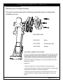
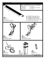
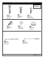
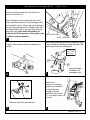
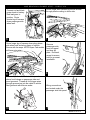
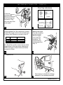
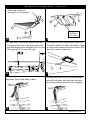
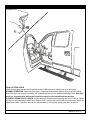
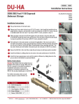
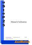
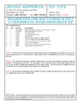
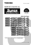
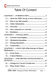
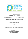
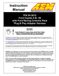
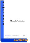
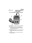
INSTALLATION GUIDE
APPLICATION
Ford F150 SuperCab
Ford F150 SuperCrew
LENGTH
MODEL YR
PART #
72”’
79”
2009 - up
2009 - up
75141-01A
75141-01A
INSTALLATION TIME
3-5
hrs
SKILL LEVEL
1
2
3
4
4= Experienced
TOOLS REQUIRED
q Safety goggles
q 8 mm socket
q 10 mm socket
q 13 mm socket
q 13 mm end wrench
q Ratchet wrench and extension
q Wire stripper
q 3/16” hex key wrench ( allen wrench)
q 4mm hex key wrench ( allen wrench)
q Electrical tape
q Weather proof caulking ( silicone
sealer )
AMP RESEARCH TECH SUPPORT 1-888-983-2204 (Press 2) Monday - Friday, 6:00 AM - 5:00 PM PST
Designed and manufactured by AMP Research®. Patent Number 6,830,257; 6,641,158; 6,834,875; 6,938,909; 6,942,233; 7,007,961; 7,055,839; 7,163,221;
7,367,574; 7,380,807; 7,398,985; 7,413,204; 7,487,986. Other US and Worldwide patents pending. Made in USA © 2010 AMP Research
5-year limited warranty. Professional installation is recommended.
www.amp-research.com
1/9
IM2996 rev 04.12.12
AMP RESEARCH POWER STEP – FORD F150
INSTALLATION GUIDE
Attaching motor to linkage assembly
The motors must be attached to the linkage assemblies before continuing the
installation process.
EXPLODED VIEW
19-03129-11
Motor
19-03179-90
Socket cap screw
19-03133-90
Washer
CAUTION: HANDLE WITH CARE.
To insure our customers receive all components with full integrity, we pack
the motors separate from their linkage assemblies. This requires that the
installer position and fasten the motor before continuing with the install.
Please follow the instructions below and handle the assembly carefully.
CAUTION: Dropping the assembly or any excessive impact MAY cause
damage to the motor.
Instructions:
1. Position the gear cover in place as shown if not already in place.
2. Seat motor into position on the three mounting bosses. This may require
an adjustment of the gear by moving the swing arms.
3. After seating into place, fasten the motor with the three motor mount
screws with T30 Torx. Tighten screws to 80 in-lbs (9N-m). Do not over
torque.
www.amp-research.com
2/9
IM2996 rev 04.12.12
AMP RESEARCH POWER STEP – FORD F150
Note: Some Applications require modification.
Application
Super Crew
Super Cab
Cut Length
79” (No Modification Required)
72” (Trim 7”)
Cut dimension
1
(A) 19-03225-11 End cap left (x1)
(B) 19-03225-12 End cap right (x1)
(C) 19-02663-90 T-nut insert (x2)
(D) 19-03236-90 Socket cap screw (x2)
(E) 19-03237-90 Nut plate (x2)
x2
20-03314-XX
Running board assembly
3
2
x2
10-03006-11
Motor linkage assembly
x2
10-03007-11
Idler linkage assembly
4
19-03694-90
Wire harness
www.amp-research.com
5
6
19-03297-98
Controller
3/9
x4
19-03354-90
Posi-Tap™ (Red/Grey)
IM2996 rev 04.12.12
AMP RESEARCH POWER STEP – FORD F150
PARTS LIST AND
HARDWARE
IDENTIFICATION
7
x8
19-02487-90
Hex bolt
11
x8
19-02488-90
U-nut
8
x8
9
12
13
x16
16-03014-90
Washer Black
15
14
x25
19-02805-90
Cable Ties 7”
www.amp-research.com
x8
19-02802-90
Socket cap screw
19-02849-90
Hex Bolt
19-03699-90
Grommet
x2
19-03339-90
Cable Ties 11”
4/9
IM2996 rev 04.12.12
AMP RESEARCH POWER STEP – FORD F150
Locate mounting points; first and last set of
holes on the inner sill.
Motor Linkage mounts toward the rear of the
truck, with the exception of the passenger side
on SuperCab trucks. Mount the motor linkage in
front on the passenger side of SuperCab trucks.
FRO
On SuperCab trucks tie up extra wire with supNT
plied wire ties. Light wires will need to be
pulled out of the harness to allow lights to be
MOTOR ASSEMBLY
installed in proper position.
IDLER ASSEMBLY
1
Mount idler assembly and motor assembly. Note:
Filing of sheet metal edge may be required if the
sheet metal holes are misaligned.
Install J-clips and start bolts with washers installed.
Torque
16 FT-LBS.
(22 N·m)
12
7
12
2
8
11
2
3
Repeat linkage
installation on
passenger side
Attach wire
harness to controller
(make sure connector
locking tabs fully
engage). Mount
controller with the two
11” tie wraps to factory
conduit.
4
Remove fuse from wire harness
4
5
www.amp-research.com
5/9
IM2996 rev 04.12.12
AMP RESEARCH POWER STEP – FORD F150
Route longer wire harness leg across firewall
through plastic cowling to driver side.
Connect red and black
power leads to battery.
Red lead goes to
positive. Route
shorter leg of harness
down passenger-side
wheel well.
6
7
Route longer leg of harness down along driverside wheel well and along frame of vehicle.
Secure with tie wraps. NOTE:Super Cab models
will have extra wire.
Remove
passenger side
front kick panel
and door sill
plate. Roll back
carpet to access
hole for grommet
installation.
9
8
Remove tape from 3/4” hole in floor panel
above front linkage on passenger side and
insert grommet. Thread all four trigger wires
through grommet up into the cabin of vehicle.
Seal grommet with silicone sealer.
Wiring connections
are located under the
passenger side kick panel.
13
4
3
16
10
11
www.amp-research.com
6/9
IM2996 rev 04.12.12
AAMMPP RREESSEEAARRCCHH PPOOW
WEERR SSTTEEPP –– FFOORRDD FF115500
Posi-Tap instrutions
Locate this
connector and
unplug for improved
access during wire
connection. Plug
color may vary from
model years.
Insert
Tighten
Insert and
Tighten
Strip 3/8”
13
12
Using supplied Posi-Tap connectors, connect
Power Step trigger wires to like colored wires
in factory wire harness as shown in step 15.
Driver Front
Pass. Front
Driver Rear
Pass. Rear
SuperCrew
SuperCab
Green/Violet
White
Green
Yellow
Green/Violet
White
Make certain each
Posi-Tap is making
positive contact
with the copper
wire inside the
insulation. Reconnect factory
wire harness from
step 12.
For SuperCab models connect the two extra
trigger wires to the same wires listed above,
Green connects to Green/Violet and Yellow
connects to White.
14
15
Replace fuse.
2
3
4
16
17
www.amp-research.com
7/9
Open doors to extend drive linkage
assembly (if not already extended).
IM2996 rev 04.12.12
AMP RESEARCH POWER STEP – FORD F150
Attach step, sliding the
mounting T-nut into position.
2
1
9
2
1
Torque
10 ft-lbs.
(13.5 Nm)
9
18
19
Affix lamps to rocker panel surface. Make sure
the lamp is affixed to a clean, flat surface. There
is a step down midway across the surface. Affix
lamp just outside of step down.
On each side of the vehicle measure from the
front edge of door line on the pinch weld to the
specified lengths below. Measure at 20” for front
LED Light and 60” for rear LED Light.
24”
65”
20
Using supplied butt connectors, connect the
lamp wires. Red to Red, Black to Black
21
Close and wrap with conduit and electrical tape.
Secure all loose wires with cable ties, with lamp
wires pulled upward to avoid any wire snagging.
23
22
www.amp-research.com
8/9
IM2996 rev 04.12.12
Replace fuse.
4
FINAL SYSTEM CHECK
Check that all doors activate the PowerStep and the LED lights work when doors open and close.
NORMAL OPERATION: When the doors open, PowerStep automatically deploys from under the vehicle.
When the doors are closed, PowerStep will automatically return to the stowed/retracted position. Note that
there is a 2-second delay before the PowerStep returns to the stowed/retracted position.
CORRECT OPERATION OF LIGHTS: All four lamps will illuminate upon opening any door of vehicle. Lamps
will stay on until restowing of both Power Steps or until 5 minutes has expired with the doors open. When the
lights timeout after 5 minutes, they can be reillumintated by closing and opening any door of vehicle.
www.amp-research.com
9/9
IM2996 rev 04.12.12
™
Congratulations on your purchase of the
genuine AMP Research PowerStep!
Here’s what you should know...
AMP Research PowerStep running boards automatically move
when the doors are opened to assist entering and exiting the vehicle.
Automatic power deploy:
The running boards will extend down and out when the doors are opened.
Automatic power stow:
The running boards will return to the stowed position when the doors are closed. There will be a 2-second
delay before the running boards move to the stowed position.
Automatic stop:
If an object is in the way of the moving running board, the running board will automatically stop.
To reset, clear any obstruction, then simply open and close the door to resume normal operation.
Manually set in the deployed (OUT) position for access to the roof:
your foot while at the same time closing the door. To resume normal operation, open and close the door.
Maintenance: In adverse conditions, debris such as mud, dirt, and salt may become trapped in the running
board mechanism, possibly leading to unwanted noise. If this occurs, manually set the running boards to
Avoid spraying the motors directly. After washing, apply silicone spray lubricant to the hinge pivot pins.
Do not apply silicone, wax or protectants like Armor All® to the running board stepping surface.
Caution! Keep hands away when the running board is in motion.
5-YEAR LIMITED WARRANTY
AMP RESEARCH warrants this product to be free from defects in material and workmanship for FIVE (5) YEARS FROM
DATE OF PURCHASE, provided there has been normal use and proper maintenance. This warranty applies to the original
purchaser only. All remedies under this warranty are limited to the repair replacement of the product itself, or the repair
or replacement of any component part thereof, found by the factory to be defective within the time period specified. The
decision to repair or replace is wholly within the discretion of the manufacturer.
for instructions. You must retain proof of purchase and submit a copy with any items returned for warranty work. Upon
completion of warranty work, if any, we will return the repaired or replaced item or items to you freight prepaid. Damage
to our products caused by accidents, fire, vandalism, negligence, misinstallation, misuse, Acts of God, or by defective parts
not manufactured by us, is not covered under this warranty.
ANY IMPLIED WARRANTIES OF MERCHANTABILITY AND/OR FITNESS FOR A PARTICULAR PURPOSE CREATED HEREBY ARE
LIMITED IN DURATION TO THE SAME DURATION AND SCOPE AS THE EXPRESS WRITTEN WARRANTY. OUR COMPANY SHALL
NOT BE LIABLE FOR ANY INCIDENTAL OR CONSEQUENTIAL DAMAGE.
Some states do not allow limitations on how long an implied warranty lasts, or the exclusion or limitation of incidental
or consequential damages, so the above limitations or exclusions may not apply to you. This warranty gives you specific
legal rights, and you may also have other rights that vary from state to state.
FOR WARRANTY ISSUES WITH THIS PRODUCT PLEASE CALL AMP RESEARCH CUSTOMER SERVICE 1-800-315-9697
WARNING
Be sure to read and precisely follow the provided instructions when installing this product. Failure to do so could place the vehicle
occupants in a potentially dangerous situation. After installing or reinstalling, re-check to insure that the product is properly installed.