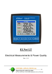
1
Table Of Content
CHAPTER 1 ─ INTRODUCTION.......................................4
1.1 — About the ElNet Energy & Power Multimeter ......... 4
1.2 — How to use this manual ................................................ 5
1.3 — Safety Information ........................................................ 7
1.4 — Warranty .......................................................................... 8
1.5 — Your comments are welcome ...................................... 9
1.6 — Disclaimer....................................................................... 10
CHAPTER 2 — INSTALLATION......................................12
2.1 — Contents of packaging ................................................ 12
2.2 — Mechanical mounting ................................................. 14
2.3 — Wiring Schematics ....................................................... 15
2.4 — Connections.................................................................... 16
CHAPTER 3 — USING THE ElNet Energy & Power
Multimeter ........................................................................19
3.1 — Front Panel .................................................................... 19
3.2 — Control Buttons ............................................................ 24
CHAPTER 4 — PARAMETER CONFIGURATION &
SETTINGS ..........................................................................26
4.1 — Settings for Current Transformer .......................... 27
4.2 — Phase Order Check ..................................................... 29
ElNet TEXT Energy & Power Multimeter
Page
1
4.3 — Clock Settings................................................................ 32
4.4 — Date Settings .................................................................. 34
4.5 — Filter Settings ................................................................ 35
4.6 — Reset Energy Values .................................................... 37
CHAPTER 5 — Text Panel Displays..................................39
5.1 — Current ............................................................................ 39
5.2 — Current in Neurtal Line ............................................. 41
5.3 — Voltage ............................................................................. 41
5.4 — Active Power (P) ........................................................... 43
5.5 — Reactive Power (Q) ...................................................... 45
5.6 — Apparent Power (S) ..................................................... 46
5.7 — Overall Power Factor and PF for each Phase ..... 47
5.8 — Frequency ....................................................................... 48
5.9 — Active Energy ................................................................ 50
5.10 — Reactive Energy ......................................................... 51
5.11 — Apparent Energy ........................................................ 53
5.12 — Harmonics .................................................................... 54
5.12.1.— Voltage Total Harmonic Distortion (THD).55
5.12.2.— Current Total Harmonic Distortion (THD)56
5.12.3.— Voltage Harmonics .......................................57
5.12.4.— Current Harmonics......................................58
CHAPTER 6 — Communications ......................................60
MODBUS Protocol ................................................................... 60
Page 2
ElNet TEXT Energy & Power Multimeter
6.1 — MODBUS Framing...................................................... 60
6.1.1.— RTU Transmission Mode...............................60
6.1.2 — The RTU Frame Format................................61
6.1.3 — Address Field ..................................................62
6.1.4 — Function Field ................................................62
6.1.5 — Data Field .......................................................63
6.1.6 — Check Field.....................................................63
6.2 — Registers for ElNet Energy & Power Multimeter . 63
6.3 — Communication Connections ................................... 69
6 4 — Communication Settings............................................ 70
6.4.1 — Address............................................................70
6.4.2 — Baud Rate .......................................................72
6.4 3 — Parity...............................................................74
6.4.4 — Stop Bit............................................................76
CHAPTER 7 — Specifications ...........................................78
Appendix A — Installation & Configuration Check List...79
Appendix B — List of Illustrations & Tables .................. 80
INDEX ...............................................................................82
ElNet TEXT Energy & Power Multimeter
Page
3
CHAPTER 1 — Introduction
CHAPTER 1 ─ INTRODUCTION
1.1 — About the ElNet Energy & Power Multimeter
All large consumers of electricity e.g. Factories, Hotels,
Hospitals, Municipalities, need to know the history of their
consumption and the quality of the power supply. Details such as
Voltage, Current, Power Factor, Hertz, Neutral Current,
Harmonics, Energy Demands and all electricity related events are
recorded in the ElNet Energy & Power Multimeter. These are
all recorded on a continual basis and can be recalled and shown
on the front panel TEXT display of the instrument with a few
simple key-strokes any time the user wishes.
The ElNet Energy & Power Multimeter is a compact unit,
installs onto a standard DIN Rail, and is especially designed to
integrate into Building Management Systems.
The Configuration and Setup is menu driven.
Communication with external devices is simple and based on
standard known technology.
The ElNet Energy & Power Multimeter boasts a new innovative
built in “Flash Memory”, which pioneers a new frontier into
electrical measurement. It has a 1 MB of ROM with a capacity of
recording up to 2 years of unusual events.
Page 4
ElNet TEXT Energy & Power Multimeter
CHAPTER 1 — Introduction
Readings & history are shown on a 2 X 16 Text Liquid Crystal
display.
Each ElNet Energy & Power Multimeter is carefully and
meticulously manufactured using quality components and the
latest production methods. Before leaving the factory each ElNet
Energy & Power Multimeter is calibrated and sent to the
customer accompanied by the test certificate and Certificate Of
Compliance (C.O.C).
1.2 — How to use this manual
We at CONTROL APPLICATIONS Ltd, envisage this manual to
be used by three types of people, i.e. the Installation Technician,
the Senior Electrical Engineer and the end User. For this reason
this manual is divided into chapters for ease of reference by each
of these different people. There could be a situation where two of
the abovementioned tasks can be combined, or in a rare instance
one person could handle all three tasks.
CHAPTER 1, Introduction, describes the ElNet Energy &
Power Multimeter, its potential users, the readings it can
provide and some of its features in brief.
CHAPTER 2, Installation, provides detailed instructions for
unpacking, mechanical mounting, and electrical wiring up
instructions for the Installation Technician.
ElNet TEXT Energy & Power Multimeter
Page
5
CHAPTER 1 — Introduction
CHAPTER 3, Using the ElNet Energy & Power Multimeter,
describes in detail the front Panel, functions of the control
buttons.
CHAPTER 4, PARAMETER CONFIGURATION & SETTINGS
explains in detail the minimum parameters settings needed by the
Senior Electrical Engineer to set up and configure the ElNet
Energy & Power Multimeter
CHAPTER 5, Front Panel Displays, is an easy to follow step-bystep guide to obtain readings, and histories for the User.
CHAPTER 6, Communications gives details about the
Communication capabilities of the ElNet Energy & Power
Multimeter, and how to Set Up
CHAPTER 7, Specifications, is a detailed list of specifications of
the ElNet Energy & Power Multimeter.
APPENDIX A, Installation & Configuration Check List, provides
a Check List to insure no important steps will be missed during
the initial set up.
APPENDIX B, List of Illustrations & Tables, shows a list of the
illustrations and Tables.
INDEX, An INDEX is provided to help find a word or a topic
easily.
Page 6
ElNet TEXT Energy & Power Multimeter
CHAPTER 1 — Introduction
1.3 — Safety Information
The purpose of this manual is to help you. Please read the
instructions carefully before performing any installation and note
any precautions.
WARNING!
•
•
•
•
•
•
•
•
Ensure that all incoming AC power and other power
sources are turned off before performing any work on the
ElNet Energy & Power Multimeter. Failure to do so may
result in serious or even fatal injury and/or equipment
damage.
If the ElNet Energy & Power Multimeter is damaged in
any way do NOT connect it to any power source.
To prevent a potential fire or shock hazard, never expose
the ElNet Energy & Power Multimeter to rain or
moisture.
Keep the surrounding area free of dirt and clutter
especially metal objects. Good housekeeping pays.
Inspect the cables periodically for cracks, kinks or any
other signs of wear
Keep children away.
Do not pull the cords.
Users should stay alert and not approach the rear of the
ElNet Energy & Power Multimeter while tired or under
the influence of alcohol, medicines or any other
ElNet TEXT Energy & Power Multimeter
Page
7
CHAPTER 1 — Introduction
•
•
chemical substance that would tend to make a person
drowsy.
Do not wear loose clothing or dangling jewelry.
Above all use common sense at all times.
1.4 — Warranty
CONTROL APPLICATIONS Ltd provides a 12- Month warranty
against faulty workmanship or components from date of dispatch
provided that the product was properly installed and used.
CONTROL APPLICATIONS Ltd does not accept liability for any
damage that may be caused by natural disasters (such as floods,
fire, earthquake, lightening etc.).
CONTROL APPLICATIONS Ltd does not accept liability for any
damage that may be caused by malfunction of the ElNet Energy
& Power Multimeter
CONTROL APPLICATIONS Ltd will advise the customer on the
proper installation and use of the ElNet Energy & Power
Multimeter, but will not accept any responsibility that the
instrument is suitable for the application for which it was
originally purchased.
Page 8
ElNet TEXT Energy & Power Multimeter
CHAPTER 1 — Introduction
This warranty may become void if the installation, parameter
configuration & setting instructions are not carried out according
to the instructions set out by CONTROL APPLICATIONS Ltd
The ElNet Energy & Power Multimeter has no user serviceable
parts and should be opened and serviced by a duly qualified
authorized representative only. The sensitive electronics
could be damaged if exposed to a static environment. This action
would void the warranty.
This warranty is limited to the repair and/or replacement at
CONTROL APPLICATION Ltd sole discretion of the defective
product during the warranty period. Repaired or replaced products
are warranted for ninety (90) days from the date of repair or
replacement, or for the remainder of the original product’s
warranty period, whichever is longer.
CONTROL APPLICATIONS Ltd is always at your service to
advise the customer on any problem that may be encountered
regarding any installation, operation, parameter & configuration
settings or maintenance.
1.5 — Your comments are welcome
CONTROL APPLICATIONS Ltd. Sincerely thank you for
choosing our ElNet Energy & Power Multimeter. We are
confident that it will provide you with many years of trouble free
service and give you all the power and energy information and
history that you expected from the instrument when you bought it.
ElNet TEXT Energy & Power Multimeter
Page
9
CHAPTER 1 — Introduction
While every effort was made to keep the information as reliable,
helpful, accurate and up to date as possible, all possible
contingencies cannot be covered. Technical or typographical
errors could occur, and we would be happy to receive any
comments criticisms or notifications of any such errors from you,
our valued customer.
Street Address:
Electronic Address:
24A HaBarzel St.
Tel-Aviv 69710
Israel
Tel: 972-3-647-4998
Fax: 972-3-647-4598
[email protected]
1.6 — Disclaimer
Information in this User Manual is subject to change without
notice and does not represent a commitment on the part of
CONTROL APPLICATIONS Ltd.
CONTROL APPLICATIONS Ltd supplies this User Manual as is
without warranty of any kind, either expressed or implied, and
reserves the right to make improvements and/or changes in the
manual or the product at any time.
Page 10
ElNet TEXT Energy & Power Multimeter
CHAPTER 1 — Introduction
While it is the intension of CONTROL APPLICATIONS Ltd to
supply the customer with accurate and reliable information in this
User Manual, CONTROL APPLICATIONS Ltd assumes no
responsibility for its use, or for any infringement of rights of the
fourth parties which may result from its use.
This User Manual could contain technical or typographical errors
and changes are periodically made to the information herein;
these changes may be incorporated in new editions of the
publication.
ElNet TEXT Energy & Power Multimeter
Page
11
CHAPTER 2 — Installation
CHAPTER 2 — INSTALLATION
In this Chapter you will find the information and instructions that
the Installation Technician needs to mount and connect the
ELNet Energy & Power Multimeter
WARNING!
•
•
•
•
During operation, hazardous voltages are present in
connecting cables and terminal blocks.
Fully qualified personnel must do all work. Failure to
follow this rule may result in serious or even fatal
injury to personnel and/or damage to equipment.
Refer to Section 1.3 Safety information before carrying
out any installation.
Read this manual thoroughly and make sure you
understand the contents before connecting the ElNet
Energy & Power Multimeter to any power source
2.1 — Contents of packaging
To unpack the ElNet Energy & Power Multimeter
The ElNet Energy & Power Multimeter is packed and shipped
in a carton approximately 18.5 cm long X 10.5 cm wide and 7 cm
high.
Page 12
ElNet TEXT Energy & Power Multimeter
CHAPTER 2 — Installation
Before opening the package, ensure the area is static free clean
and dry.
Without using any sharp instruments, carefully open the carton of
the ElNet Energy & Power Multimeter.
Please check the contents of the carton, it should contain:1.
Your new ElNet Energy & Power Multimeter.
ElNet TEXT User Manual (This book).
2.
3.
4.
5.
6.
Test Certificate and Certificate of Compliance (C.O.C).
4 X two pole connector plugs
2 X three pole connector plugs
1 X Four pole connector plugs
ElNet TEXT Energy & Power Multimeter
Page 13
CHAPTER 2 — Installation
2.2 — Mechanical mounting
NOTE!
Do not mount the ElNet Energy & Power
Multimeter too close to any main electrical
conductors.
Allow sufficient space to carry out maintenance to the
ElNet Energy & Power Multimeter
The ElNet Energy & Power Multimeter is manufactured with a
standard DIN rail mounting. To mount, simply choose a suitable
location and click into position.
Figure 2-1. Mount onto DIN Rail
Page 14
ElNet TEXT Energy & Power Multimeter
CHAPTER 2 — Installation
2.3 — Wiring Schematics
Figure 2-3. Schematic Wiring Diagram
ElNet TEXT Energy & Power Multimeter
Page 15
CHAPTER 2 — Installation
2.4 — Connections
NOTE!
A future planned option the ElNet Energy & Power
Multimeter will be the ability to measure electrical
properties for two separate electrical systems. The
only restrictions envisaged will be physical and
geographical constraints
To connect the ElNet Energy & Power Multimeter
All Connections, except those to the CT core of the ElNet Energy
& Power Multimeter are made via terminal connector plugs
(Voltage input, Power Supply, earth/ground etc.).
Recommended max. tightening torque for the connector screws is
0.5 Nm
The CT cores of the ElNet Energy & Power Multimeter are
located externally on the front of the instrument and the lead from
the leg of the external Current Transformer must pass through in
the correct direction.
NOTE!
Ensure all the connections to the leads of the current
transformer wiring is secure and there is no mechanical
strain on the wire
Page 16
ElNet TEXT Energy & Power Multimeter
CHAPTER 2 — Installation
Insert the lead from side “L” of the Current Transformers of Line
1 through the top of the CT core I1A, of the ElNet Energy &
Power Multimeter.
NOTE!
•
Ensure the leads from leg “L” of the Current
Transformer on Line 1 passes through the top of CT
core I1A.
•
Ensure the other end of the lead emerging from the
bottom of C T core I1A is looped back and connected
to leg “K” of the Current Transformer on Line 1
WARNING!
WARNING
Never allow an open circuit between the two Current
Transformers.
An open circuit will cause damage to equipment.
Repeat the procedure for Line 2 and Line 3.
Connect the rest the connections to the ElNet Energy & Power
Multimeter by means of terminal connecto plugs.
ElNet TEXT Energy & Power Multimeter
Page 17
CHAPTER 2 — Installation
Designation
Description
Remarks
V1
Direct from Busbar1
Through a 6Amp fuse
V2
Direct from Busbar2
Through a 6Amp fuse
V3
Direct from Busbar3
Through a 6Amp fuse
N
Direct from Neutral Line
I1A
From Current
Transformer on Line1
Note the correct direction to
insert the lead
I2A
From Current
Transformer on Line2
Note the correct direction to
insert the lead
I3A
From Current
Transformer on Line3
Note the correct direction to
insert the lead
~
Power 220 V AC
Bridged from V3
N
Neutral
Bridged from the neutral
Line
Earth/Ground
Table 2-1 Connections
Page 18
ElNet TEXT Energy & Power Multimeter
CHAPTER 3 — Using the ElNet Energy & Power Multimeter
CHAPTER 3 — USING THE ElNet Energy & Power
Multimeter
In this chapter you will find descriptions and functions of the
front panel and the control buttons and how to use them.
3.1 — Front Panel
To operate the front panel
The Front Panel has a two line TEXT screen and 3 operating
buttons located below the screen.
All readings are shown on the 2 X 16 text screen. How to obtain
the readings is explained in detail in Chapter 5.
The Control Buttons and their functions are fully explained in
Section 3-2.
TEXT Screen
Figure 3-1. Front Panel
Control Buttons
ElNet TEXT Energy & Power Multimeter
Page 19
CHAPTER 3 — Using the ElNet Energy & Power Multimeter
To obtain Readings
All information contained in the Powermeter is viewed by
navigating through a logical Hierarchy Menu. To arrive at each
reading, follow a logical step-by-step procedure starting from Top
Level and progress down to 2nd Level, 3rd Level etc.
To do this, look in the lowest level for the specific reading required,
then go back up and start from the top Level for that reading.
Page 20
ElNet TEXT Energy & Power Multimeter
CHAPTER 3 — Using the ElNet Energy & Power Multimeter
Hierarchy of Menus
Top Level: Energy
G
Geenneerraall
Active Energy
PPoow
weerr
Reactive Energy
CCoonnffiigguurraattiioonn
Apparent Energy
L1
L1
L1
L2
L2
L2
L3
L3
L3
ALL
ALL
ALL
Top Level: EEnneerrggyy
Current
General
Voltage
PPoow
weerr
Power Factor
L1
L1
L1
L2
L2
L2
L3
L3
L3
ALL
L1-2
ALL
Neutral
Line
L2-3
CCoonnffiigguurraattiioonn
Frequency
L1
L2
L3
L3-1
ElNet TEXT Energy & Power Multimeter
Page 21
CHAPTER 3 — Using the ElNet Energy & Power Multimeter
Hierarchy of Menus Continued
Top Level: EEnneerrggyy
G
Geenneerraall
Active Power
Power
H
Haarrm
moonniiccss CCoonnffiigguurraattiioonn
Reactive Power
Apparent Power
L1
L1
L1
L2
L2
L2
L3
L3
L3
ALL
ALL
ALL
Top Level: EEnneerrggyy
G
Geenneerraall
PPoow
weerr
Harmonics CCoonnffiigguurraattiioonn
THD Volts
THD Current
Volts Harmonics
Current Harmonics
L1
L1
# 1-32 for L1
# 1-32 for L1
L2
L2
# 1-32 for L2
# 1-32 for L2
L3
L3
# 1-32 for L3
# 1-32 for L3
Page 22
ElNet TEXT Energy & Power Multimeter
CHAPTER 3 — Using the ElNet Energy & Power Multimeter
Hierarchy of Menus Continued
Top Level: EEnneerrggyy
Set Time
G
Geenneerraall
PPoow
weerr
Set Date
Second
Day
Minute
Month
Hour
Year
H
Haarrm
moonniiccss Configuration
CT Configure
G
Geenneerraall
Communication
Information
Technical
Statistics
Set by Code
Parity
Stop Bit
Address
Voltage
Current
Power
Freq.
CT Ratio
Top Level: EEnneerrggyy
Baud
Filter
PPoow
weerr
H
Haarrm
moonniiccss Configuration
Line Status
Volt L1
Volt L2
Volt L3
Curr. L1
Curr. L2
Curr, L3
Phase Order
ElNet TEXT Energy & Power Multimeter
Page 23
CHAPTER 3 — Using the ElNet Energy & Power Multimeter
3.2 — Control Buttons
Function of the Control Buttons
The ElNet Energy & Power Multimeter has three control buttons
arranged below the display screen. These require slight finger
pressure to click. The User and Senior Electrical Engineer use
these Control Buttons to view readings and perform all the Set Up
functions.
Esc
Figure 3-2. Control Buttons
Button
moves to the next level down (the one the arrow is
pointing to).
OR
selects a field to be set or changed (during Set UP)
Page 24
ElNet TEXT Energy & Power Multimeter
CHAPTER 3 — Using the ElNet Energy & Power Multimeter
is a spin control that rolls the text upwards one
line per click
OR
at the lowest level, rolls to each reading of that
group
OR
modifies the selected field (during Set UP)
Button
Esc
Button
returns to the previous step
NOTE!
In the event of a general power failure, the ElNet
Energy & Power Multimeter returns to the last
screen displayed.
ElNet TEXT Energy & Power Multimeter
Page 25
CHAPTER 4 — Parameter Configuration & Settings
CHAPTER 4 — PARAMETER CONFIGURATION &
SETTINGS
In this chapter you will find instructions to set the minimum
settings that are necessary to allow the ElNet Energy & Power
Multimeter to function properly.
WARNING!
•
•
•
Page 26
The selection, installation and settings of the Current
Transformer is the most vital and fundamental action
required to ensure the accurate functioning of the ElNet
Energy & Power Multimeter.
It is essential to know the ratio of the Current Transformer
being installed into the system in order to set the
parameter for the Current Transformer correctly.
All three main current Lines MUST have Current
Transformers of the same ratio installed onto them.
ElNet TEXT Energy & Power Multimeter
CHAPTER 4 — Parameter Configuration & Settings
4.1 — Settings for Current Transformer
Hierarchy Tree of Current Transformer Settings
Top Level — Configuration
2nd Level — CT Configure
3rd Level — Set CT Screen # 1
4th Level —Set CT Screen # 2
To set or change settings for Current Transformer
NOTE!
The most important setting necessary for the proper
functioning of the ElNet Energy & Power
Multimeter is the Current Transformer setting.
1
From the Main Menu roll to Configuration
Configuration
Energy
ElNet TEXT Energy & Power Multimeter
Page 27
CHAPTER 4 — Parameter Configuration & Settings
2
3
Click
Roll to CT Configure
CT Configure
Filter
4
Click
The Set Current Transformer Screen # 1 appears
CT= 0005 -> 5
To Set CT
...
Figure 4-1. Set Current Transformer Screen # 1
5
Click
The Set Current Transformer Screen # 2 appears
CT= 0005 -> 5
Set CT Value
Figure 4-2. Set Current Transformer Screen # 2
Page 28
ElNet TEXT Energy & Power Multimeter
CHAPTER 4 — Parameter Configuration & Settings
6
Click
to change CT Value
NOTE!
Each click rolls the value up by 5 units.
4.2 — Phase Order Check
NOTE!
To avoid any problems arising from incorrect Voltage
Connections or accidental reversal of Current
Transformer Connections, it is necessary to perform a
Phase Order Check before continuing.
Top Level — Configuration
2nd Level — Line Status
3rd Level — Check Line Status Volts Line 1,2 & 3
Check Line Status Current Line 1,2 & 3
Check Phase Order
ElNet TEXT Energy & Power Multimeter
Page 29
CHAPTER 4 — Parameter Configuration & Settings
To perform Line Status Check (Connection Check) & Phase
Order Check
1
From the Main Menu roll to Configuration
Configuration
Energy
2
Click
3
Roll to Line Status
Line Status
Set Time
4
Click
The Line Status & Phase Order screen appears
Volt Line 1:OK
Volt line 2:OK
Figure 4-3. Check Volt & Current Connections
5
Roll to Volts Line1,2 & 3
Page 30
ElNet TEXT Energy & Power Multimeter
CHAPTER 4 — Parameter Configuration & Settings
6
Roll to Curr. Line1,2 & 3
Voltage and Current Messages
Table 4-1 Voltage and Current Messages
Message
OK
Voltage
Voltage present on Lines
7
Current present in
Lines and synchronized
with Voltage Lines
Wired in incorrect
direction
OPP
NO
Current
No Voltage
No current
Roll to Phase Order
Curr.Line 3:--Phase Order:OK
Figure 4-4. Check Phase Order
ElNet TEXT Energy & Power Multimeter
Page 31
CHAPTER 4 — Parameter Configuration & Settings
Phase Order Messages
Message
Voltage
OK
Correct Phase Order of Voltage Connections
OPP
Incorrect Phase Order i.e. Line 2 does not follow Line 1
and/or Line 1 does not follow Line3
Table 4-2 Phase Order Messages
4.3 — Clock Settings
Hierarchy Tree of Clock Settings
Top Level — Configuration
2nd Level — Set Time
3rd Level — Set Time Screen # 1
4th Level —Set Time Screen # 2
To set Time
1
From the Main Menu roll to Configuration
2
3
Click
Roll to Set Time
Set Time
Set Date
Page 32
ElNet TEXT Energy & Power Multimeter
CHAPTER 4 — Parameter Configuration & Settings
4
Click
The Set Time Screen # 1 appears
Time 00:00:00
To Set Time ...
Figure 4-5. Set Time Screen # 1
5
Click
The Set Time Screen # 2 appears
00:--:-Set Time
Figure 4-6. Set Time Screen # 2
Click
to select Hours Minutes Seconds
Click
to change Hours (24 hour clock), Minutes, Seconds
ElNet TEXT Energy & Power Multimeter
Page 33
CHAPTER 4 — Parameter Configuration & Settings
4.4 — Date Settings
Hierarchy Tree of Date Settings
Top Level — Configuration
2nd Level — Set Date
3rd Level — Set Date Screen # 1
4th Level —Set Date Screen # 2
To set Date
1
From the Main Menu roll to Configuration
2
3
Click
Roll to Set Date
Set Date
CT Configure
4
Click
The Set Date Screen # 1 appears
Date 00/00/00
To Set Date ...
Figure 4-7. Set Date Screen # 1
Page 34
ElNet TEXT Energy & Power Multimeter
CHAPTER 4 — Parameter Configuration & Settings
5
Click
The Set Date Screen # 2 appears
00/--/-Set Date
Figure 4-8. Set Date Screen # 2
Click
to select Day, Month, Year (up to 99)
Click
to change, Day, Month, Year
4.5 — Filter Settings
All readings in the ElNet Energy & Power Multimeter are read and
displayed every second. In a “noisy” system these readings would
show wild fluctuations. Fluctuations can be “smoothed” out by
applying Time Average Filters.
Time Average Filters utilizes the “Sliding Window” method. A
calculation is made of the sum of a preset number of readings,
divided by the same number to gives a new continuously moving
average. This new calculated reading appears as the new reading
every second
Recommended factory setting = 3 seconds.
ElNet TEXT Energy & Power Multimeter
Page 35
CHAPTER 4 — Parameter Configuration & Settings
NOTE!
The Time Average Filter does not affect any internal
calculations or accumulation of data.
Hierarchy Tree of Filter Settings
Top Level — Configuration
2nd Level — Set Filter
3rd Level — Set Voltage Filter
Set Current Filter
Set Power Filter
Set Frequency Filter
To set Voltage, Current, Power, or Frequency Filters
All 4 Filter settings procedures are identical
1
From the Main Menu roll to Configuration
2
3
Click
Roll to Filter
4
5
Click
Roll to either Voltage, Current, Power, or Frequency Filters
Page 36
ElNet TEXT Energy & Power Multimeter
CHAPTER 4 — Parameter Configuration & Settings
6
Click
The Set Filter screen appears
Volt.Filter=
1
Press
To Set
Figure 4-9. Set Filter Screen
7
Click
to set Filter (one second per click)
NOTE!
Filter settings can be set between 1 and 50 seconds
4.6 — Reset Energy Values
Hierarchy Tree of Reset Energy Values
Top Level — Configuration
2nd Level — Technical
To Reset Energy Values
1
From the Main Menu roll to Configuration
2
3
Click
Roll to Technical
ElNet TEXT Energy & Power Multimeter
Page 37
CHAPTER 4 — Parameter Configuration & Settings
4
Hold
for 4 seconds
The Enter Command Code screen appears
Enter Cmd Code
000
Figure 4-10. Enter Command Code
5
Roll the code till 642
6
Click
NOTE!
If you overrun the code, continue to 999 and start
again.
The Energy Reset screen appears for 1 second
Energy Reset..
Done !!
Figure 4-11. Energy Reset
Page 38
ElNet TEXT Energy & Power Multimeter
CHAPTER 5 — Panel Displays
CHAPTER 5 — Text Panel Displays
In this chapter you will find instructions on how to obtain the
readings that the ElNet Energy & Power Multimeter provides,
e.g., Current, Voltage Power, Power Factor, Energy, and Harmonics.
5.1 — Current
Hierarchy Tree of Current displays
Top Level — General
2nd Level — Current
3rd Level — Current for Line 1 Line 2 & Line 3
To display Current for all 3 Phases
1
From the Main Menu roll to General
General
Power
2
Click
3
Roll to Current
ElNet TEXT Energy & Power Multimeter
Page 39
CHAPTER 5 — Panel Displays
Current
Voltage
4
Click
The Current Screen Appears
Current L1
0.0
Amper
Figure 5-1. Current Screen
5
Roll to Current Line 2 and Line 3
Esc
6
Click
to return to General Menu
Esc
7
Click
Page 40
to return to Main Menu
ElNet TEXT Energy & Power Multimeter
CHAPTER 5 — Panel Displays
5.2 — Current in Neurtal Line
By using Vector calculations the ElNet Energy & Power
Multimeter calculates the Current in the Neutral Line.
To display Current in Neutral Line
Repeat Steps 1 to 5 as found in Section 5.1.
6
Roll to Current In Neutral line
5.3 — Voltage
Hierarchy Tree of Voltage displays
Top Level — General
2nd Level — Voltage
3rd Level — Voltage for Line 1 Line 2 & Line 3
Voltage between Line 1-2 Line 2-3 Line 3-1
To display Voltage for all 3 Phases and across Phases
1
From the Main Menu roll to General
General
Power
ElNet TEXT Energy & Power Multimeter
Page 41
CHAPTER 5 — Panel Displays
2
Click
3
Roll to Voltage
Voltage
Power Factor
4
Click
The Voltage Screen Appears
Voltage L1
000.0
Volt
Figure 5-2. Voltage Screen
5
Roll to Voltage Line 2, Line 3
Voltage between Line 1-2 Line 2-3 Line 3-1
Page 42
ElNet TEXT Energy & Power Multimeter
CHAPTER 5 — Panel Displays
Parameter
Description
Units
L1
L2
L3
L12
L23
L13
Voltage from Line1 to Neutral
Voltage from Line2 to Neutral
Voltage from Line3 to Neutral
Voltage across Line1 and Line2
Voltage across Line2 and Line3
Voltage across Line1 and Line3
Volts
Volts
Volts
Volts
Volts
Volts
5.4 — Active Power (P)
Hierarchy Tree of Active Power displays
Top Level — Power
2nd Level — Active Power
3rd Level —Active Power for Line 1 Line 2 & Line 3
Active Power for All Lines
To display Active Power for all 3 phases
1
From the Main Menu roll to Power
Power
Harmonics
2
3
Click
Roll to Active Power
ElNet TEXT Energy & Power Multimeter
Page 43
CHAPTER 5 — Panel Displays
Active Power
Reactive Power
4
Click
The Active Power Screen Appears
Act. Power L1
0.0
Watt
Figure 5-3. Active Power Screen
5
Roll to Active Power Line 2, Line 3, ALL
Parameter
P
Q
S
ΣP
ΣQ
ΣS
PF
Page 44
Description
Unit
Active Power for each Line
Watts
Reactive Power for each Line
VAR
Apparent Power for each Line
VA
Total Active Power for all 3 Lines
Watts
Total Reactive Power for all 3 Lines VAR
Total Apparent Power for all 3 Lines VA
Power Factor
ElNet TEXT Energy & Power Multimeter
CHAPTER 5 — Panel Displays
5.5 — Reactive Power (Q)
Hierarchy Tree of Reactive Power displays
Top Level — Power
2nd Level — Reactive Power
3rd Level —Reactive Power for Line 1 Line 2 & Line 3
Reactive Power for All Lines
To display Reactive Power for all 3 phases
1
From the Main Menu roll to Power
Power
Harmonics
2
3
Click
Roll to Reactive Power
Reactive Power
Apparent Power
4
Click
ElNet TEXT Energy & Power Multimeter
Page 45
CHAPTER 5 — Panel Displays
The ReActive Power Screen Appears
Rea. Power L1
0.0
VAR
Figure 5-4. Reactive Power Screen
5
Roll to Active Power Line 2, Line 3, ALL
5.6 — Apparent Power (S)
Hierarchy Tree of Reactive Power displays
Top Level — Power
2nd Level — Apparent Power
3rd Level — Apparent Power for Line 1 Line 2 & Line 3
Apparent Power for All Lines
To display Apparent Power for all 3 phases
1
From the Main Menu roll to Power
Power
Harmonics
2
3
Click
Roll to Apparent Power
Page 46
ElNet TEXT Energy & Power Multimeter
CHAPTER 5 — Panel Displays
Apparent Power
Active Power
4
Click
The Apparent Power Screen Appears
App. Power L1
0.0
VA
5
Figure 5-5. Apparent Power Screen
Roll to Apparent Power Line 2, Line 3, ALL
5.7 — Overall Power Factor and PF for each Phase
Hierarchy Tree of Power Factor displays
Top Level — General
2nd Level —Power Factor
3rd Level —Power Factor Line 1 Line 2 & Line 3 ALL
To display Power Factor for all 3 phases
1
From the Main Menu roll to General
ElNet TEXT Energy & Power Multimeter
Page 47
CHAPTER 5 — Panel Displays
2
3
Click
Roll to Power Factor
Power Factor
Frequency
4
Click
The Power Factor Screen Appears
Power Factor
0.0
Figure 5-6. Power Factor Screen
5
Roll to Power Factor Line 2, Line 3, ALL
5.8 — Frequency
Hierarchy Tree of Frequency displays.
Top Level — General
2nd Level — Frequency
3rd Level — Frequency for Line 1 Line 2 & Line 3
Page 48
ElNet TEXT Energy & Power Multimeter
CHAPTER 5 — Panel Displays
To display Frequency for all 3 phases
1
From the Main Menu roll to General
2
Click
3
Roll to Frequency
Frequency
Current
4
Click
The Frequency Screen Appears
Frequency
L1
50.0
Hertz
Figure 5-7. Frequency Screen
5
Roll to Frequency line1, Line 2, Line 3.
ElNet TEXT Energy & Power Multimeter
Page 49
CHAPTER 5 — Panel Displays
5.9 — Active Energy
Hierarchy Tree of Active Energy displays
Top Level — Energy
2nd Level — Active Energy
3rd Level — Active Energy for Line 1 Line 2 & Line 3
Active Energy for All Lines
To display Active Energy for all 3 phases
1
From the Main Menu roll to Energy
2
4
Click
Roll to Active Energy
Active Energy
Reactive Energy
Page 50
ElNet TEXT Energy & Power Multimeter
CHAPTER 5 — Panel Displays
5
Click
The Active Energy Screen Appears
Act. Energy L1
0.000
KWh
Figure 5-8. Active Energy Screen
6
Roll to Active Energy Line 1, Line 2, Line 3, ALL
5.10 — Reactive Energy
Hierarchy Tree of Reactive Energy displays
Top Level — Energy
2nd Level — Reactive Energy
3rd Level — Reactive Energy for Line 1 Line 2 & Line 3
Reactive Energy for All Lines
ElNet TEXT Energy & Power Multimeter
Page 51
CHAPTER 5 — Panel Displays
To display Reactive Energy for all 3 phases
1
From the Main Menu roll to Energy
2
3
Click
Roll to Reactive Energy
Reactive Energy
Apparent Energy
4
Click
The ReActive Energy Screen Appears
Rea. Energy L1
0.000
KVARh
Figure 5-9. Active Energy Screen
5
Roll to Reactive Energy Line 2, Line 3, ALL
Page 52
ElNet TEXT Energy & Power Multimeter
CHAPTER 5 — Panel Displays
5.11 — Apparent Energy
Hierarchy Tree of Apparent Energy displays
Top Level — Energy
2nd Level — Apparent Energy
3rd Level — Apparent Energy for Line 1 Line 2 & Line 3
Apparent Energy for All Lines
To display Apparent Energy for all 3 phases
1
From the Main Menu roll to Energy
2
3
Click
Roll to Apparent Energy
Apparent Energy
Taoz (Rates)
4
Click
ElNet TEXT Energy & Power Multimeter
Page 53
CHAPTER 5 — Panel Displays
The Apparent Energy Screen Appears
App. Energy L1
0.000
KVAh
Figure 5-10. Apparent Energy Screen
5
Roll to Apparent Energy Line 2, Line 3, ALL
5.12 — Harmonics
NOTE!
Poor Harmonics could invoke a fine and can be
improved by adding capacitors or simply switching a
suspect appliance off and noting any improvement.
The ElNet Energy & Power Multimeter is capable of displaying
Volt and Current Harmonics.
In addition, Total Harmonics Distortion (THD) for Volts and Current
can also be displayed on the TEXT Screen.
Page 54
ElNet TEXT Energy & Power Multimeter
CHAPTER 5 — Panel Displays
5.12.1.— Voltage Total Harmonic Distortion (THD)
Hierarchy Tree of Voltage Total Harmonic Distortion displays
Top Level — Harmonics
2nd Level — Voltage THD
3rd Level — Voltage THD. % for Line 1, Line 2 & Line 3
To display Voltage Total Harmonic Distortion (THD)
1
From the Main Menu roll to Harmonics
2
Click
3
Roll to Voltage THD
Voltage THD
Current THD
4
Click
The THD – Voltage Screen Appears
THD-Voltage L1
0.000
%
Figure 5-11.Voltage Total Harmonics Distortion Screen
5
Roll to THD Voltage for Line 2 and Line 3
ElNet TEXT Energy & Power Multimeter
Page 55
CHAPTER 5 — Panel Displays
5.12.2.— Current Total Harmonic Distortion (THD)
Hierarchy Tree of Current Total Harmonic Distortion displays
Top Level — Harmonics
2nd Level — Current THD
3rd Level —Current THD. % for Line 1, Line 2 & Line 3
To display Current Total Harmonic Distortion (THD)
1
From the Main Menu roll to Harmonics
2
Click
3
Roll to Current THD
Current THD
Voltage Harmon.
4
Click
The THD –Current Screen Appears
THD-Current L1
0.000
%
Figure 5-12.Current Total Harmonics Distortion Screen
5
Roll to THD Current
Page 56
% for Line 2 and Line 3
ElNet TEXT Energy & Power Multimeter
CHAPTER 5 — Panel Displays
5.12.3.— Voltage Harmonics
Hierarchy Tree of Volt Harmonics displays
Top Level — Harmonics
2nd Level — Voltage Harmonics
3rd Level — Volt Harmonics from 1st to 32nd for Line 1,2 &3
To display Volt Harmonics From 1st to 32nd
1
From the Main Menu roll to Harmonics
2
Click
3
Roll to Voltage Harmonics
Voltage Harmon.
Current Harmon
4
Click
The Voltage Harmonics Screen Appears
L1-Volt,Har# 1
0.
%
Figure 5-13.Volt Harmonics from 1st to 32nd Screen
ElNet TEXT Energy & Power Multimeter
Page 57
CHAPTER 5 — Panel Displays
5
Click
to change to Line 1, Line 2 & Line 3
6
Click
to read Harmonics % from 1st to 32
5.12.4.— Current Harmonics
Hierarchy Tree of Current Harmonics displays
Top Level — Harmonics
2nd Level — Current Harmonics
3rd Level — Current Harmonics from 1st to 32nd Line 1,2 &3
To display Current Harmonics From 1st to 32nd
1
From the Main Menu roll to Harmonics
2
Click
3
Roll to Current Harmonics
Current Harmon.
Voltage THD
4
Click
Page 58
ElNet TEXT Energy & Power Multimeter
CHAPTER 5 — Panel Displays
The Current Harmonics Screen Appears
L1-Cur, Har# 1
0.000
%
Figure 5-14.Current Harmonics from 1st to 32nd Screen
5
Click
to change to Line 1, Line 2 & Line 3
6
Click
to read Harmonics % from 1st to 32
ElNet TEXT Energy & Power Multimeter
Page 59
CHAPTER 6 — Communications
CHAPTER 6 — Communications
MODBUS Protocol
The ElNet Energy & Power Multimeter has a serial interface
port allowingt direct interface with an external communication
network supporting the MODBUS Protocol.
MODBUS is an Industry Standard, widely known and commonly
used communications protocol. Using MODBUS provides
communication between a PC and up to 247 Powermeter slaves on a
common line- the PC being the master and the Powermeters the
slaves. The PC initiates the transaction (either a query or broadcast)
and the Powermeter/s responds. Powermeters respond to the master
Pc’s request, but will not iniate any transmission on its own. The PC
sends a single Query transaction and the Powermeter responds in a
single response frame and is capable of only one query and one
response at a time
6.1 — MODBUS Framing
6.1.1.— RTU Transmission Mode
MODBUS uses the standard Remote Terminal Unit (RTU)
transmission mode. RTU mode sends data in 8-bit binary Even parity
or 8-bit binary NO parity data format. For the ElNet Energy &
Power Multimeter to successfully communicate, choose one in the
communication Set Up.
Page 60
ElNet TEXT Energy & Power Multimeter
CHAPTER 6 — Communications
Field
No. of bits
Start bit
Data bits
Parity
Stop bit
1
8
1
1
Table 6-1 RTU Data Format
6.1.2 — The RTU Frame Format
Query and response information is sent in frames. Each frame
contains:
Address
Function (See Section 6.1.4 for descriptions of functions),
Data
Check.
Address Function
Data
Check
8 bits
8 bits
N * 8 bits 16 bits
Table 6-2 R T U Message Frame Format
If the receiving device (Powermeter) detects a time laps of five
characters, then it will assume the message is incomplete and will
flush the frame. The device (Powermeter) then assumes that the next
byte received will be an address. The maximum query and response
message length is 256 bytes includuing check characters.
ElNet TEXT Energy & Power Multimeter
Page 61
CHAPTER 6 — Communications
6.1.3 — Address Field
Each Powermeter is designated in a network system by a user
assigned address. The Address can be any number between 1 and
247. The Powermeter will only respond to it’s own specificically
assigned address.
6.1.4 — Function Field
The function field contains the code that tells the Powermeter what
action to perform.
The ElNet Energy & Power Multimeter uses and responds to four
standard Message Format Functions.
Function 03
Function 04
Function 06
Function 16
Function
Function 03
Function 04
Function 06
Function 16
Page 62
Meaning in MODBUS
Action
Read holding register
Obtain data from Powermeter
(Read register)
Read input register
Obtain data from Powermeter
(Read register)
Preset single register
Transmit data to Powermeter
(Write single register)
Preset multiple register Transmit data to Powermeter
(Write multiple registers)
Table 6-3 Function Codes
ElNet TEXT Energy & Power Multimeter
CHAPTER 6 — Communications
6.1.5 — Data Field
The Data field contains the body of the message and contains
instructions from the PC master to the Powermeter slave to perform
a particuler action or respond to a query. The reply message from the
Powermeter will be information contained in one or more of it’s
registers.
6.1.6 — Check Field
The error check field contains the result of Cyclical Redundancy
Check (CRC). The start of the message is ignored in calculating the
CRC.
For more detailed information on CRC, refer to the MODBUS
Protocol Reference Guide.
6.2 — Registers for ElNet Energy & Power Multimeter
The ElNet Energy & Power Multimeter is capable of supporting
either Function 03 or Function 04 Message Format(See Table 1-3).
In a reply to a query from the PC master for a reading from a
particular field, the response from the Powermeter can be either in
Format 03 or Format 04 but will depend on which Format the qeuery
was originally sent.
The difference is significant because by using Function 03 the
ELNet will only send the INTEGER part of the field value
requested and the PC master will only display the INTEGER part
of the field value.
ElNet TEXT Energy & Power Multimeter
Page 63
CHAPTER 6 — Communications
Function 04, on the other hand, is capable of sending two separate
halves of the full FLOAT requested information (each half
contained in a separate register). Then it is the task of the PC
master to merge the two halves into a full FLOAT reply. (For more
detailed information See IEEE Standard 754 Floating-Point).
E.G. 1 If the user’s PC master supports Function 03, then the reply
will contain the INTEGER part of the field only.
The PC master requests the Voltage from Line1, and the
actual Voltage in that field is 230.5 Volts.
Function 03 will respond with the INTEGER only i.e. 230V.
E.G. 2 If the user PC master supports Function 04, then the reply
will contain the information stored in the two registers
asssigned to that field and will contain the full, accurate reply.
The PC master requests the Voltage from Line1, and the actual
Voltage in that field is 230.5 Volts.
Function 04 will respond with a composite reply of both register
1 and 2 giving the full FLOAT value (in IEEE Format) from that
field i.e. 230.5V.
Page 64
ElNet TEXT Energy & Power Multimeter
CHAPTER 6 — Communications
No
1
2
3
4
5
6
7
8
9
10
11
12
13
14
15
16
17
18
19
20
21
22
23
24
MODBUS
Register
Field Description
Type
1-2
3-4
5-6
7-8
9-10
11-12
13-14
15-16
17-18
19-20
21-22
23-24
25-26
27-28
29-30
31-32
33-34
35-36
37-38
39-40
41-42
43-44
45-46
47-48
Voltage Line 1
Voltage Line 2
Voltage Line 3
Voltage between line 1 and Line 2
Voltage between line 2 and Line 3
Voltage between line 3 and Line 1
Current in Line 1
Current in Line 2
Current in Line 3
Active Power Line 1
Active Power Line 2
Active Power Line 3
Combined Active Power Line 1+2 +3
Apparent Power Line 1
Apparent Power Line 2
Apparent Power Line 3
Combined Apparent Power Line 1+2+3
Reactive Power Line 1
Reactive Power Line 2
Reactive Power Line 3
Combined Reactive Power Line 1+2+3
Power Factor Line 1
Power Factor Line 2
Power Factor Line 3
Read
Read
Read
Read
Read
Read
Read
Read
Read
Read
Read
Read
Read
Read
Read
Read
Read
Read
Read
Read
Read
Read
Read
Read
ElNet TEXT Energy & Power Multimeter
Page 65
CHAPTER 6 — Communications
25
26
27
28
29
30
31
32
33
34
35
36
37
38
39
40
41
42
43
44
45
46
47
48
49
50
49-50
51-52
53-54
55-56
57-58
59-60
61-62
63-64
65-66
67-68
69-70
71-72
73-74
75-76
77-78
79-80
81-82
83-84
85-86
87-88
89-90
91-92
93-94
95-96
97-98
99-100
Page 66
Combined Power Factor for Line 1+2+3
Frequency Line 1
Frequency Line 2
Frequency Line 3
Current Neutral Line
Active Energy
Reactive Energy
Apparent Energy
Time from 01 01 2000 in seconds
ADDRESS
BAUD RATE
PARITY
Current Transformer Ratio
Timed average Voltage
Timed average Current
Read
Read
Read
Read
Read
Read
Read
Read
Read
Read
Read
Read
Read
Read/Write
Read/Write
Read/Write
ElNet TEXT Energy & Power Multimeter
CHAPTER 6 — Communications
51
52
53
54
55
56
57
58
59
60
61
62
63
64
65
66
67
68
101-102
103-104
105-106
107-108
109-110
111-112
113-114
115-116
Timed average Power
Timed avaerge Frequqncy
THD for Volts Line 1
THD for Volts Line 2
THD for Volts Line 3
THD for Current Line 1
THD for Current Line 2
THD for Current Line 3
119-120
121-122
123-124
125-126
127-128
129-130
131-132
133-134
135-136
Active Power Line 1
Active Power Line 2
Active Power Line 3
Reactive Power Line 1
Reactive Power Line 2
Reactive Power Line 3
Apparent Power Line 1
Apparent Power Line 2
Apparent Power Line 3
Read
Read
Read
Read
Read
Read
Read
Read
Read
301
302
601-602
603-604
1st Harmonics for Volts Line 1
2nd Harmonics for Volts Line 1
Read
Read
⇓
331
332
333
⇓
661-662
663-664
665-666
⇓
31st Harmonics for Volts Line 1
32nd Harmonics for Volts Line 1
1st Harmonics for Volts Line 2
ElNet TEXT Energy & Power Multimeter
Read/Write
Read/Write
Read
Read
Read
Read
Read
Read
⇓
Read
Read
Read
Page 67
CHAPTER 6 — Communications
334
667-668
⇓
⇓
363
364
365
366
725-726
727-728
729-730
731-732
⇓
⇓
395
396
397
398
789-790
791-792
793-794
795-796
⇓
⇓
427
428
429
430
853-854
855-856
857-858
859-860
⇓
⇓
31st Harmonics for Volts Line 2
32nd Harmonics for Volts Line 2
1st Harmonic for Volts Line 3
2nd Harmonics for Volts Line 3
⇓
31st Harmonics for Vots Line 3
32nd Harmonics for Volts Line 3
1st Harmonics for Current Line 1
2nd Harmonics for Current Line 1
⇓
⇓
31st Harmonics for Current Line 1
32nd Harmonics for Current Line 1
1st Harmonics for Current Line 2
2nd Harmonics for Current Line 2
⇓
459
460
461
462
917-918
919-920
921-922
923-924
⇓
⇓
491
492
981-982
983-984
Page 68
2nd Harmonics for Volts Line 2
31st Harmonics for Current Line 2
32nd Harmonicsfor Current Line 2
1st Harmonics for Current Line 3
2nd Harmonics for Current Line 3
⇓
31st Harmonics for Current Line 3
32nd Harmonics for Current Line 3
ElNet TEXT Energy & Power Multimeter
Read
⇓
Read
Read
Read
Read
⇓
Read
Read
Read
Read
⇓
Read
Read
Read
Read
⇓
Read
Read
Read
Read
⇓
Read
Read
CHAPTER 6 — Communications
Table 6-4 Registers
6.3 — Communication Connections
The ElNet Energy & Power Multimeter communicates through
RS485. The connections can be seen from the front, (bottom left)
and are made by means of the connectors provided.
TEXT Screen
Figure 6-1. Communication Connections
ElNet TEXT Energy & Power Multimeter
Page 69
CHAPTER 6 — Communications
Pin Designation
Description
COM –
1
– of RS485
COM +
2
+ of RS485
Earth/Ground
Table 6-5 Connections
6 4 — Communication Settings
To enable the User to connect the ElNet Energy & Power
Multimeter to a PC master computer for successful
communications, the Communication Setup parameters of both must
match; i.e. the port of the PC master and the configuration settings
of the Powermeter.
Address
Baud Rate
Parity
Stop Bit
6.4.1 — Address
Each Powermeter in a communication system must have it’s own
unique address.
Because the ElNet Energy & Power Multimeter works on
MODBUS, the available addresses are from ‘1’ to ‘31’
Page 70
ElNet TEXT Energy & Power Multimeter
CHAPTER 6 — Communications
Hierarchy Tree of Address Setup
Top Level — Configuration
2nd Level — Communication
3rd Level — Address
To set up Address
1
From the Main Menu roll to Configuration
Configuration
Energy
2
3
Click
Roll to Communication
Communication
Information
4
5
Click
Roll to Address
Address
Baud
ElNet TEXT Energy & Power Multimeter
Page 71
CHAPTER 6 — Communications
6
Click
The Set Address Screen # 1 appears
Address= XX
Press
To Set
Figure 6-2. Set Address Screen
7
Click
to set Address
6.4.2 — Baud Rate
The Baud Rate is the communication speed in Bits per second
(BPS) that the ElNet Energy & Power Multimeter
communicates with the PC master. The better the communication
line Quality, the faster the communications may be.
If the communication line is routed through a “noisy”
environment, it may be necessary to decrease the Baud Rate
Available Baud Rates for the ElNet Energy & Power Multimeter: 300
600
1200
2400
Page 72
bps
bps
bps
bps
ElNet TEXT Energy & Power Multimeter
CHAPTER 6 — Communications
4800
9600
19200
38400
bps
bps
bps
bps
Hierarchy Tree of Baud Rate Setup
Top Level — Configuration
2nd Level — Communication
3rd Level — Baud Rate
To set Baud Rate
1
From the Main Menu roll to Configuration
Configuration
Energy
2
3
Click
Roll to Communication
Communication
Information
ElNet TEXT Energy & Power Multimeter
Page 73
CHAPTER 6 — Communications
4
5
Click
Roll to Baud
Baud
Parity
6
Click
The Set Baud Screen appears
Baud=
Press
XXXXX
To Set
Figure 6-3. Set Baud Rate Screen
7
Click
to change Baud Rate
6.4 3 — Parity
The choices of parity are either EVEN or NONE.
Page 74
ElNet TEXT Energy & Power Multimeter
CHAPTER 6 — Communications
Hierarchy Tree of Parity Setup
Top Level — Configuration
2nd Level — Communication
3rd Level — Parity
To set Parity
1
From the Main Menu roll to Configuration
2
3
Click
Roll to Communication
Communication
Information
4
5
Click
Roll to Parity
Parity
Stop Bit
6
Click
ElNet TEXT Energy & Power Multimeter
Page 75
CHAPTER 6 — Communications
The Set Parity Screen appears
Parity=XXXX
Press
To Set
Figure 6-4. Set Parity Screen
6.4.4 — Stop Bit
The choice of parity is either 1 or 2.
Hierarchy Tree of Stop Bit Setup
Top Level — Configuration
2nd Level — Communication
3rd Level — Stop Bit
To set Stop Bit
1
From the Main Menu roll to Configuration
2
3
Click
Roll to Communication
Communication
Information
Page 76
ElNet TEXT Energy & Power Multimeter
CHAPTER 6 — Communications
4
Click
5
Roll to Stop Bit
6
Click
The Set Stop Bit Screen appears
Stop Bit=1
Press
To Set
Figure 6-5. Set Stop Bit Screen
ElNet TEXT Energy & Power Multimeter
Page 77
CHAPTER 7 — Specifications
CHAPTER 7
— Specifications
Item
Description
Power requirements
110/230VAC,60/50 Hz, 30VA
Dimensions
(HxWxD) 96x159x57 mm
Shipping Weight
450 gr
Voltage limits
1000VAC
Current limits
50A
Enclosure material
ABS + Antiflame
Display
Liquid Crystal 2 X 16
Operating temperature
-20 - + 60 C
Storage temperature
-20 - + 80 C
Humidity
0- 90 RH%
Voltage input terminals
VL – E10 1708
Communication port
RS485
Mounting
Standard DIN Rail
Overload Protection
1 Amp Fuse
All technical specifications are subject to change without notice.
Page 78
ElNet TEXT Energy & Power Multimeter
Check List
Appendix A — Installation & Configuration Check List
INSTALLATION CHECK LIST
Description
Date
Signature
Check contents of packaging
Remove from packaging
Mount Multimeter
Connect Multimeter power supply
Connect 3 Current Transformer
Connect 3 Voltage lines
Connect Neutral line
Set parameter for Current Transformer
Connect Communication lines
Appendix A Table - Installation & Configuration Check List
ElNet TEXT Energy & Power Multimeter
Page 79
List of Illustrations
Appendix B — List of Illustrations & Tables
LIST OF ILLUSTRATIONS
Figure 2-1. Mount onto DIN Rail
Figure 2-3. Schematic Wiring Diagram
Figure 3-1. Front Panel
Figure 3-2. Control Buttons
Figure 4-1. Set Current Transformer Screen # 1
Figure 4-2. Set Current Transformer Screen # 2
Figure 4-3. Check Volt & Current Connections
Figure 4-4. Check Phase Order
Figure 4-5. Set Time Screen # 1
Figure 4-6. Set Time Screen # 2
Figure 4-7. Set Date Screen # 1
Figure 4-8. Set Date Screen # 2
Figure 4-9. Set Filter Screen
Figure 4-10. Enter Command Code
Figure 4-11. Energy Reset
Figure 5-1. Current Screen
Figure 5-2. Voltage Screen
Figure 5-3. Active Power Screen
Figure 5-4. Reactive Power Screen
Figure 5-5. Apparent Power Screen
Figure 5-6. Power Factor Screen
Figure 5-7. Frequency Screen
Figure 5-8. Active Energy Screen
Figure 5-10. Apparent Energy Screen
Page 80
ElNet TEXT Energy & Power Multimeter
List of Illustrations
Figure 5-11.Voltage Total Harmonics Distortion Screen
Figure 5-12.Current Total Harmonics Distortion Screen
Figure 5-13.Volt Harmonics from 1st to 32nd Screen
Figure 5-14.Current Harmonics from 1st to 32nd Screen
Figure 6-11. Communication Connections
Figure 6-12. Set Address Screen
Figure 6-13. Set Baud Rate Screen
Figure 6-14. Set Parity Screen
Figure 6-15. Set Stop Bit Screen
LIST OF TABLES
Table 2-1 Connections
Table 6-1 RTU Data Format
Table 6-2 R T U Message Frame Format
Table 6-3 Function Codes
Table 6-4 Registers
Table 6-5 Connections
Appendix A Table - Installation & Configuration Check List
ElNet TEXT Energy & Power Multimeter
Page 81
INDEX
INDEX
A
AC power, 7
address, 10, 61, 62, 70
Apparent Energy, 53
B
Baud Rate, 72, 73
Building Management Systems, 4
C
C.O.C, 5
cables, 7, 12
carton, 13
Certificate Of Compliance, 5
Check Field, 63
Check List, 6, 79
children, 7
Clock Settings, 32
comments, 9, 10
commitment, 10
Communications, 6, 60
conductors., 14
Configuration, 26
consumption, 4
control buttons, 19
cracks, 7
CT core, 16
Current, 4, 39
Current Transformer, 26, 27
Page 82
D
damage, 7
Data Field, 63
Date Settings, 34
defective, 9
DIN Rail, 4, 14
Disclaimer, 10
F
Filter Settings, 35
fire, 7
Flash Memory, 4
format, 61
Frequency, 48
Front Panel, 19
Function Field, 61
functions, 24
H
Harmonics, 4, 54
hazardous voltages, 12
Hierarchy Tree, 20
I
illustrations, 80
improvements, 10
injury, 7
integer, 63, 64
ElNet TEXT Energy & Power Multimeter
INDEX
L
liability, 8
Liquid Crystal display, 5
List of Tables, 81
M
mechanical mounting, 14
minimum settings, 26
MODBUS, 60
moisture, 7
N
natural disasters, 8
O
open circuit, 17
P
packaging, 12, 79
Parity, 66, 74
Phase Order Check, 29
Power Factor, 47
power failure, 25
power source, 7, 12
precautions, 7
R
ratio, 26
registers, 63, 65
repair, 9
replacement, 9
S
safety information, 7, 12
service, 9
settings Current Transformer, 27
signs of wear, 7
Specifications, 6, 78
static free, 13
Stop Bit, 61, 70, 76
T
terminal connector, 17
test certificate, 5
Text Screen, 19
Total Harmonics Distortion, 54,
55, 56
V
void the warranty, 9
Voltage, 4, 41
W
warranty, 8
warranty period, 9
ElNet TEXT Energy & Power Multimeter
Page 83