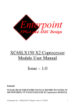
1
Merrick6 User Manual
Issue – 1.0
© Enterpoint Ltd. – Merrick6 Manual – Issue 1.0 18/03/2012
1
Kit Contents
You should receive the following items with your Merrick6 development kit:
1 - Merrick6 Board
2 - Programming Cable
3 - A Programming adapter will be required in order to use the Enterpoint PROG2, PROG3
or standard Xilinx 2x7x2mm programing cables. The JTAG connectors on Merrick6 are
2x6x1.27mm headers.
Foreword
PLEASE READ THIS ENTIRE MANUAL BEFORE PLUGGING IN
OR POWERING UP YOUR MERRICK6 BOARD.
PLEASE TAKE SPECIAL NOTE OF THE WARNINGS WITHIN
THIS MANUAL.
Trademarks
Spartan-6, ISE, Webpack, EDK, COREGEN, Xilinx are the registered trademarks of Xilinx Inc,
San Jose, California, US.
Merrick6 is a trademark of Enterpoint Ltd.
© Enterpoint Ltd. – Merrick6 Manual – Issue 1.0 18/03/2012
2
Contents
Kit Contents
Foreword
Trademarks
MERRICK6
Introduction
MERRICK6 FEATURES
FPGAs
CONNECTIONS BETWEEN ARRAY FPGAs
CONNECTIONS BETWEEN ARRAY AND CONTROL FPGAs
CLOCK CONNECTIONS BETWEEN ARRAY AND CONTROL FPGAs
SPI FLASH
DDR3 MEMORY
LEDS
ETHERNET CONTROLLER
MEMORY CARD HOLDER
CLOCK GENERATOR
PCIE INTERFACE
EXPANSION
POWER CONNECTIONS
THERMAL MANAGEMENT
POWER REGULATORS
PROGRAMMING MERRICK6
Programming the Control FPGA
© Enterpoint Ltd. – Merrick6 Manual – Issue 1.0 18/03/2012
2
2
2
4
5
6
8
9
10
12
14
15
17
18
20
21
22
23
24
25
26
27
28
3
Programming the Array FPGAs
MECHANICAL
Medical and Safety Critical Use
Warranty
Support
© Enterpoint Ltd. – Merrick6 Manual – Issue 1.0 18/03/2012
30
33
34
34
34
4
MERRICK6
Merrick6
Merrick 6 in a mini ITX motherboard
© Enterpoint Ltd. – Merrick6 Manual – Issue 1.0 18/03/2012
5
Introduction
Welcome to your Merrick6 board. Merrick6 is a Spartan-6 based FPGA development board offering
a highly powerful approach to prototyping FPGA and System designs .
Merrick6 provides high performance computing in a low power package, with a power
dissipation of between 15 and 150w. Features include an array containing 6 Xilinx
XC6SLX150 FPGAs together with 12 4 Gigabit DDR3 DRAMs. In addition the board
features high speed routing across the array and array reload(under 0.25 seconds), a board
stacking interface and a PCI-E interface. We are also able to provide a separate algorithm
implementation service for customers.
The aim of this manual is to assist in using the main features of Merrick6.
There are features that are beyond the scope of the manual. Should you need to use these features
then please email [email protected] for detailed instructions.
Merrick6 is currently fitted with XC6SLX150-2FGG484C Spartan-6 devices. Other variants may be
offered at a later date or as an OEM product. Please contact us on [email protected]
should you need further information.
© Enterpoint Ltd. – Merrick6 Manual – Issue 1.0 18/03/2012
6
Merrick6 Features
Expansion/stacking
interface
Control FPGA
XC6SLX150T
Clock Generator
1Gbit/s Ethernet
PHY
PCIE
Interface
4 GBit ddr3
serving
Control
FPGA
2x4 GBit
ddr3 per
FPGA
Array of 6
xc6slx150csg484
FPGAs
2x128Mb
SPI Flash
User
memory
Memory
Card
Holder
Rear of Merrick6 board (3d model)
© Enterpoint Ltd. – Merrick6 Manual – Issue 1.0 18/03/2012
7
Your Merrick6 will be supplied un-programmed. Unless you have bought an OEM product your
board will be supplied with either a Prog2 parallel port programming cable or a Prog3 USB port
programming cable.
The Spartan-6 FPGAs on the standard Merrick6 board are not supported by the free Webpack
version of ISE. You will need version 11.1 SP4, or later, of the ISE tools, which are available from
Xilinx to enter and build a design. Using this tool in conjunction with your supplied programming
cable you will also be able to program the Spartan-6s, and the supporting SPI Flash, that are on
Merrick6.
© Enterpoint Ltd. – Merrick6 Manual – Issue 1.0 18/03/2012
8
FPGAs
1
4
2
5
3
6
Merrick6 has a total of 7 FPGAs. There are 6 array FPGAs and one Control FPGA. The standard
arrangement is:
Control FPGA – XC6SLX150T-FGG900C
Array FPGAs - XC6SLX150-FGG484C
Merrick6 is normally available with commercial grade -2 speed devices fitted in the XC6SLX150
size. Should you have an application that needs different size FPGAs, industrial parts or faster
speed grades please contact sales for a quote at [email protected].
© Enterpoint Ltd. – Merrick6 Manual – Issue 1.0 18/03/2012
9
CONNECTIONS BETWEEN ARRAY FPGAs
The Merrick6 Array FPGAs are interconnected as shown in the diagram below.
There are 20 connections between each of the FPGAs in a column. These connections are arranged
as 10 LVDS pairs. The interconnections are shown in the table below:
FPGA BANK 0 PIN
FPGA BANK 2 PIN
FPGA BANK 0 PIN
FPGA BANK 2 PIN
B14
W17
B18
T17
A14
V17
A18
T18
C15
Y17
E16
AA21
A15
AB17
D17
AB21
D15
W18
B12
R15
C16
Y18
A12
R16
B16
V18
C13
U16
A16
V19
D14
U17
C17
Y19
C14
T15
A17
AB19
A13
T16
© Enterpoint Ltd. – Merrick6 Manual – Issue 1.0 18/03/2012
10
CONNECTIONS BETWEEN CONTROL FPGA AND ARRAY
FPGAs
There are 32 connections between the Control FPGA and each of the Array FPGAs:
These connections a connect to pairs of IO both at the Array FPGA and at the Controller FPGA. At
the array FPGA the IO are on banks 0 and 2 which are fully LVDS capable. At the Controller
FPGA the signals are connected to banks 0, 1, 2, 3 or 4. Banks 0 and 2 are fully VVDS capable but
banks 1 and 3 have limitations to their LVDS capability which are described in the Xilinx Spartan6
user guide (see ww.xilinx.co.uk).
The connections are shown in the table below. The number in parentheses eg (3) shows the IO bank
to which the signal connects at the Control FPGA.
MASTER FPGA
ALL
ARRAY
FPGAS
FPGA1
FPGA2
FPGA3
FPGA4
FPGA5
FPGA6
E5 (4)
R21 (1)
Y14 (2)
G5 (4)
T28 (1)
AB12 (2)
C5
E4 (4)
R22 (1)
AA14 (2)
G4 (4)
T30 (1)
AC12 (2)
A5
H4 (4)
R29 (1)
AE17 (2)
J5 (4)
W29 (1)
AC11 (2)
D6
H3 (4)
R30 (1)
AF17 (2)
J4 (4)
W30 (1)
AD11 (2)
C6
J6 (4)
R24 (1)
AC19 (2)
G3 (4)
P26 (1)
AB13 (2)
B6
H6 (4)
R25 (1)
AD19 (2)
G1 (4)
P27 (1)
AC13 (2)
A6
K2 (4)
L21 (0)
AD18 (2)
H2 (4)
P22 (1)
AC16 (2)
C7
© Enterpoint Ltd. – Merrick6 Manual – Issue 1.0 18/03/2012
11
K1 (4)
K21 (0)
AE18 (2)
H1 (4)
P23 (1)
AD16 (2)
A7
L5 (4)
U24 (1)
AE21 (2)
K4 (4)
F23 (0)
AG6 (2)
B8
L4 (4)
U25 (1)
AF21 (2)
K3 (4)
E23 (0)
AH6 (2)
A8
M4 (4)
V23 (1)
AF16 (2)
J3 (4)
W27 (1)
AF7 (2)
D9
M3 (4)
V24 (1)
AG16 (2)
J1 (4)
W28 (1)
AG7 (2)
C8
M2 (4)
P28 (1)
AE23 (2)
L3 (4)
G22 (0)
AH7 (2)
C9
M1 (4)
P30 (1)
AF23 (2)
L1 (4)
F22 (0)
AK7 (2)
A9
H17 (0)
Y24 (1)
AC5 (3)
C16 (0)
AB21 (2)
Y2 (3)
AA4
G17 (0)
Y25 (1)
AC4 (3)
A16 (0)
AC21 (2)
Y1 (3)
AB4
M13 (0)
AA29 (1)
Y7 (3)
B15 (0)
AF25 (2)
Y4 (3)
Y3
L13 (0)
AA30 (1)
Y6 (3)
A15 (0)
AG25 (2)
Y3 (3)
AB3
L14 (0)
AD28 (1)
AA10 (3)
G20 (0)
AD12 (2)
AH3 (3)
V7
K14 (0)
AD30 (1)
AA9 (3)
F20 (0)
AE12 (2)
AK3 (3)
W8
K10 (0)
U27 (1)
AB10 (2)
P24 (1)
AD10 (2)
T4 (3)
U8
J10 (0)
U28 (1)
Y12 (2)
P25 (1)
AE10 (2)
T3 (3)
T8
J18 (0)
AE24 (2)
AD4 (3)
F17 (0)
AD20 (2)
W7 (3)
AB5
H18 (0)
AF24 (2)
AD3 (3)
E17 (0)
AE20 (2)
W6 (3)
Y5
M15 (0)
AC29 (1)
Y9 (3)
F19 (0)
AE19 (2)
AJ4 (3)
Y6
K15 (0)
AC30 (1)
Y8 (3)
E19 (0)
AF19 (2)
AK4 (3)
W6
H7 (0)
T24 (1)
W14 (2)
J22 (0)
V28 (1)
V8 (3)
R7
G7 (0)
T25 (1)
Y13 (2)
H22 (0)
V30 (1)
V7 (3)
T7
M10 (0)
R27 (1)
AB14 (2)
M23 (1)
U29 (1)
T2 (3)
R8
L10 (0)
R28 (1)
AC14 (2)
M24 (1)
U30 (1)
T1 (3)
R9
F15 (0)
AB28 (1)
AB10 (2)
H16 (0)
W21 (1)
AG4 (3)
V5
E15 (0)
AB30 (1)
AB9 (2)
G16 (0)
W22 (1)
AH4 (3)
U6
© Enterpoint Ltd. – Merrick6 Manual – Issue 1.0 18/03/2012
12
CLOCK CONNECTIONS BETWEEN THE CONTROL FPGA AND
ARRAY FPGAS
There are 4 connections (2 pairs) between the Control FPGA and each Array FPGA which are
primarily intended for the distribution of clock signals, but may be used as General purpose IO if
they are not required for this purpose.
At the Array FPGA these signals connect to Global Clock pins. The connections are shown in the
table below. The number in parentheses eg (3) shows the IO bank to which the signal connects at
the Control FPGA.
MASTER FPGA
ALL
ARRAY
FPGAS
FPGA1
FPGA2
FPGA3
FPGA4
FPGA5
FPGA6
L11 (0)
AC27 (1)
AE3 (3)
F11 (0)
AB17 (2)
V10 (3)
W12
K11 (0)
AC28 (1)
AE1 (3)
E11 (0)
AD17 (2)
V9 (3)
Y12
J12 (0)
AD27 (1)
AE4 (3)
L12 (0)
AE9 (2)
P7 (3)
Y11
H12 (0)
AD27 (1)
AF4 (3)
K12 (0)
AF9 (2)
P6 (3)
AB11
© Enterpoint Ltd. – Merrick6 Manual – Issue 1.0 18/03/2012
13
SPI FLASH MEMORY
CONTROL FPGA
CONFIGURATION SPI
FLASH
There are 3 SPI flash memory devices fitted to Merrick6. One is connected to the Control FPGA for
configuration code. The second and third devices are connected to the Control FPGA for extra code
storage. The details of these devices are shown below.
USER STORAGE
FLASH
1. The W25Q128BV SPI flash memory U39 device configures the Control FPGA when it is
powered providing a suitable bitstream is programmed into the device. The W25Q128BV has a
capacity of 128Mbits with a single configuration bitstream for the XC6SLX150T taking 33.9Mbits .
Any remaining space can be used for alternative configurations or code and data storage. The
W25Q128BV is a quad flash device, and with suitably chosen configuration options will allow the
Merrick board to achieve the 100ms minimum PCIE configuration time.
After configuration the SPI Flash can be accessed via the following pins of the FPGA:
SIGNAL
CCLK
MISO0/D
MISO1/Q
MISO2/WP
MISO3/HOLD
CS
FPGA PIN
AJ26
AK25
AJ25
AB20
AC20
AK6
W25Q128BV PIN
6
5
2
3
7
1
The flash memory can be programmed using direct SPI programming from the 6x2 programming
connector J5. A Programming adapter will be required in order to use the standard Enterpoint or
Xilinx 2x7x2mm programming cables.
© Enterpoint Ltd. – Merrick6 Manual – Issue 1.0 18/03/2012
14
2 and 3. These W25Q128BV SPI flash memory devices U10 and U11 are available for user code
and data storage. They are connected to GPIO on the Control FPGA and can be used in either x1 or
x4 mode.
The SPI Flash devices can be accessed via the following pins of the FPGA:
SIGNAL
CCLK
MISO0/D
MISO1/Q
MISO2/WP
MISO3/HOLD
CS
FPGA PIN U10
AD22
AC23
AD24
AC24
AE22
AB23
FPGA PIN U11
AJ17
AA21
AK15
AJ15
AK17
AK16
© Enterpoint Ltd. – Merrick6 Manual – Issue 1.0 18/03/2012
W25Q128BV PIN
6
5
2
3
7
1
15
DDR3 MEMORY
CONTROL FPGA
DDR3
ARRAY LEFT
DDR3
ARRAY RIGHT
DDR3
Merrick6 has 13 4GBIT DDR3 Micron MT41J256M16 devices as standard. Each Array FPGA has
2 memory devices connected to it and the Control FPGA has one. Each Array FPGA connects to
one DDR3 to its left on Bank 3 and a second to its right on bank 1. These devices are organised as
32 Meg x 16 x 8 banks. They are supported by the hard core memory controller that is in the
Spartan-6 FPGAs. To add these cores to your design the COREGEN tool, part of the ISE suite, will
generate implementation templates in VHDL or Verilog for the configuration that you want to use.
More details on the memory controller can be found in the user guide.
http://www.xilinx.com/support/documentation/user_guides/ug388.pdf.
The DDR3 devices have 14 address lines and 16 data lines to address all the available memory,
which can be accessed at speeds of 1.87ns. More details of the DDR3 can be found in
http://download.micron.com/pdf/datasheets/dram/ddr3/1Gb_DDR3_SDRAM.pdf.
The DDR3 sites have the following connections to the FPGAs:
DDR3 FUNCTION
DDR_A0
DDR_A1
DDR_A2
DDR_A3
DDR_A4
DDR_A5
DDR_A6
DDR_A7
DDR_A8
Control
FPGA PIN
D28
D30
C30
E29
F27
H26
H27
C29
B27
Array FPGA
LEFT DDR3
H2
H1
H5
K6
F3
K3
J4
H6
E3
© Enterpoint Ltd. – Merrick6 Manual – Issue 1.0 18/03/2012
RIGHT DDR3
F21
F22
G20
F20
K20
K19
E20
C20
16
DDR_A9
DDR_A10
DDR_A11
DDR_A12
DDR_A13
DDR_A14
DDR_A15
DDR_BA0
DDR_BA1
DDR_BA2
DDR_CS_N
DDR_RAS_N
DDR_WE_N
DDR_DQ0
DDR_DQ1
DDR_DQ2
DDR_DQ3
DDR_DQ4
DDR_DQ5
DDR_DQ6
DDR_DQ7
DDR_DQ8
DDR_DQ9
DDR_DQ10
DDR_DQ11
DDR_DQ12
DDR_DQ13
DDR_DQ14
DDR_DQ15
DDR_LDM
DDR_LDQS
DDR_LDQS_N
DDR_UDM
DDR_UDQS
DDR_UDQS_N
DDR_ODT
DDR_CAS_N
DDR_RESET_N
DDR_CKE
DDR_CLK_N
DDR_CLK
NOCONNECT*
TERMINATION*
A27
F26
A26
B30
A28
A29
G25
D27
C27
D26
L25
K26
E26
H28
H30
G29
G30
G27
G28
F28
F30
L27
L28
L29
L30
M26
M27
M28
M30
J28
J29
J30
J27
K28
K30
E30
K27
C26
B29
E28
E27
N24
L24
E1
G4
C1
D1
G6
F5
H8
G3
G1
F1
H8
K5
F2
N3
N1
M2
M1
J3
J1
K2
K1
P2
P1
R3
R1
U3
U1
V2
V1
L4
L3
L1
M3
T2
T1
J6
K4
C3
D2
H3
H4
W3,W1,T4,T3,U4,V3,M5
Y2
C22
G19
F19
D22
D19
D20
P20
J17
K17
H18
K18
H21
H19
N20
N22
M21
M22
J20
J22
K21
K22
P21
P22
R20
R22
U20
U22
V21
V22
L19
L20
L22
M20
T21
T22
G22
H22
F18
D21
J19
H20
M19,P19,W20,W22,L17
C19
The signals shown shaded in yellow are terminated using suitable arrangements of resistors.
* The Noconnect and Termination pins are required when building some versions of the memory
controller core. ISE Version 13 and above permit greater flexibility when assigning these pins than
earlier ISE versions. Other unconnected pins may also be available on the Array FPGA Banks. See
the schematic diagrams for further information.
© Enterpoint Ltd. – Merrick6 Manual – Issue 1.0 18/03/2012
17
LEDS
Array FPGA LEDs
Control FPGA LED
Merrick6 has 25 LEDs. The Control FPGA has a single red LED which is connected to pin AJ1.
Each array FPGA has one each of Red, Yellow, Blue and Green LEDs.
Blue
Green
Yellow
Red
Red
Green
Yellow
Blue
The relevant IO pin for an LED needs to be asserted LOW to ensure the specified LED turns on. It
may be necessary to assign the pins to 'Z' (High Impedance) in order for the LEDs to be completely
'off'.
The table below shows the connections between the Array FPGAs and the LEDs.
COLOUR
RED
YELLOW
GREEN
BLUE
FPGA PIN
B1
A2
B2
A4
© Enterpoint Ltd. – Merrick6 Manual – Issue 1.0 18/03/2012
18
ETHERNET CONTROLLER
Ethernet controller
Merrick6 has a Micrel KSZ9021RL 10/100/1000 Mbps Ethernet PHY fitted, which implements a
RGMII version 1.3 transceiver interface. For further information and the component datasheet
please refer to www.micrel.com.
The connections between the KSZ9021RL device and the Control FPGA are shown in the table
below. They are arranged as 4 transmit signals, 4 receive signals, and a 13-bit support bus.
RJ45 Magnetically isolated
Enternet socket
© Enterpoint Ltd. – Merrick6 Manual – Issue 1.0 18/03/2012
19
SIGNAL NAME
KSZ9021RL PIN
FPGA PIN
ETH_TX0
24
C1
ETH_TX1
25
B1
ETH_TX2
26
B2
ETH_TX3
27
A2
ETH_RX0
42
A3
ETH_RX1
41
D4
ETH_RX2
38
C4
ETH_RX3
36
A4
ETH_SUPP1 (ETH_TX_ER)
31
D3
ETH_SUPP2 (ETH_TCK)
32
A5
ETH_SUPP3 (ETH_TXEN_ER)
33
B3
ETH_SUPP4 (ETH_RX_CLK)
46
D2
ETH_SUPP5 (ETH_CLK_MAC_FREQ)
43
D5
ETH_SUPP6 (ETH_MDC)
48
D1
ETH_SUPP7 (ETH_MDIO)
49
E1
ETH_SUPP8 (ETH_INT_N)
51
E3
ETH_SUPP9 (ETH_RESET_N)
56
C5
ETH_SUPP10 (ETH_CLK_TO_MAC)
55
F2
ETH_SUPP11 (ETH_SEL1)
19
F3
ETH_SUPP12 (ETH_SEL0)
21
F4
ETH_SUPP13 (ETH_CLOCK_25MHZ)
60
F1
Signals shown shaded yellow have components between the FPGA pin and the Ethernet controller
pin.
© Enterpoint Ltd. – Merrick6 Manual – Issue 1.0 18/03/2012
20
MEMORY CARD HOLDER
MEMORY
CARD
HOLDER
Further access to data can be achieved using the Memory Card Socket which is connected to the
Control FPGA. To use this socket in a design you may need to obtain a license from the SD
Association at http://www.sdcard.org/home/.
The connections between the Memory Card Socket and the Control FPGA are shown below:
MEMORY CARD
SOCKET
DATA 0
DATA 1
DATA 2
DATA 3
CMD
CLK
POWER_ON_N
CARD PRESENT
FPGA PIN
D6
A6
C6
B6
A7
B7
C8
D8
The POWER_ON_N pin must be set LOW for power to be supplied to the Memory Card Socket.
© Enterpoint Ltd. – Merrick6 Manual – Issue 1.0 18/03/2012
21
CLOCK GENERATOR
CLOCK GENERATOR
Merrick6 has an IDT5V19EE901NLGI clock generator capable of generating four single ended
clocks and one differential clock which are all connected to FPGA. The clock generator is
controlled by an SPI interface. More information and a datasheet for this device can be obtained
from .www.idt.com
The connections between the Clock Generator and the FPGA are shown below:
IDT5V19EE901 Function
CLKA
CLKB
CLK C
CLK1_P
CLK1_N
EXP_CLK1_P
EXP_CLK1_N
CLK2
CLK_X
SCLK
SDAT
IDT5V19EE901 Pin
7
8
24
10
11
14
15
23
30
19
18
FPGA Pin
AA1
AA3
V3
W5
W4
AB2
AB1
U1
V4
V1
V2
The Spartan-6 has PLLs and DCMs to produce multiples, divisions and phases of the clock for
specific application requirements. Please consult the Spartan-6 datasheet available from the Xilinx
website at http://www.xilinx.com if multiple clock signals are required.
© Enterpoint Ltd. – Merrick6 Manual – Issue 1.0 18/03/2012
22
PCIE INTERFACE
Merrick6 has a x1 PCIE interface which is connected to the control FPGA. The pin out of the
SpartanTM-6 FPGA has been chosen such that
the PCI interface follows the pinout for the XilinxTM SpartanTM-6 hard core for PCIe which can be
generated automatically by the XilinxTM Core Generator.
The connections between the PCIe connector and the FPGA are shown below.
SIGNAL NAME
PCIE CONNECTOR PIN FPGA PIN
HS_REFCLK0_P
A13
AJ13
HS_REFCLK0_N
A14
AK13
HS_TX0_P
A16
AJ9
HS_TX0_N
A17
AK9
HS_RX0_P
B14
AG10
HS_RX0_N
B15
AH10
PCIE_PRESENT#1
A1 LINKED TO B17
PCIE_PRESENT#2
B17 LINKED TO A1
PCIE_PWRGD
A11
© Enterpoint Ltd. – Merrick6 Manual – Issue 1.0 18/03/2012
AK2
23
EXPANSION CONNECTOR
The high speed MGT connections of the Control FPGA that are not used for the PCIE interface are
routed to a connector (J6, Samtec type QRF8-026-01-l-RA) at the top of the Merrick6 PCB. This is
intended to allow high speed interconnection between the Merrick6 and other circuitry for example
stacking of multiple Merrick6 boards.
The connections between the Control FPGA and the expansion connector are shown below.
SIGNAL
NAME
EXPANSION
FPGA
CONNECTOR PIN PIN
SIGNAL
NAME
EXPANSION
CONNECTOR PIN
FPGA
PIN
HS_REFCLK1_P
9
B13
HS_TX4_P
2
B9
HS_REFCLK1_N
11
A13
HS_TX4_N
4
A9
HS_TX1_P
14
AJ11
HS_RX4_P
1
D10
HS_TX1_N
16
AK11
HS_RX4_N
3
C10
HS_RX1_P
13
AG12
HS_TX5_P
6
B11
HS_RX1_N
15
AH12
HS_TX5_N
8
A11
HS_TX_CLK_P
10
W19
HS_RX5_P
5
D12
HS_TX_CLK_N
12
Y19
HS_RX5_N
7
C12
HS_TX2_P
18
AJ21
HS_TX6_P
26
B21
HS_TX2_N
20
AK21
HS_TX6_N
28
A21
HS_RX2_P
17
AG20
HS_RX6_P
25
D20
HS_RX2_N
19
AH20
HS_RX6_N
27
C20
HS_TX3_P
22
AJ23
HS_TX7_P
30
B23
HS_TX3_N
24
AK23
HS_TX7_N
32
A23
HS_RX3_P
21
AG22
HS_RX7_P
29
D22
HS_RX3_N
23
AH22
HS_RX7_N
31
C22
Signals shown shaded yellow are connected to J6 via 100nF capacitors.
© Enterpoint Ltd. – Merrick6 Manual – Issue 1.0 18/03/2012
24
POWER CONNECTIONS
Merrick3 is powered principally from the 12V supply on the disk drive connector.
POWER CONNECTOR
(DISK DRIVE TYPE)
7A fuse
2.6A fuse
A limited 12V supply can be provided using the PCIE connector, but the current available is limited
to 2A so this should be avoided unless you know that your design does not consume more current
than this.
The Merrick6 is protected by 2 fuses, a 2.6A resettable fuse on the PCIE power feed and a 7A fast
blow fuse (Littlefuse Series 154) on the supply from the Disk Drive Connector.
© Enterpoint Ltd. – Merrick6 Manual – Issue 1.0 18/03/2012
25
THERMAL MANAGEMENT
For many applications, particularly where the DDR3 devices are being used at high speed, it will be
necessary to implement a system of thermal management to dissipate the heat generated in the
FPGAs. 4 holes have been provided for mouning a heatsink or fan over the FPGA array. The design
of the thermal management system will depend upon the design implemented in the FPGAs, any
enclosure the customer may be using for the Merrick6 board, and the mechanical arrangement of
the system into which the Merrick6 board is to integrated.
Mounting holes for
heatsink or fan
The mounting holes are 3.175mm diameter.
© Enterpoint Ltd. – Merrick6 Manual – Issue 1.0 18/03/2012
26
POWER REGULATORS
7
6
5
1
2
4
3
Merrick6 has 7 regulators supplying 3.3V, 1.5V, 1.2V and 0.75V power rails.
WARNING – REGULATORS CAN BECOME HOT IN NORMAL OPERATION ALONG
WITH THE BOARDS THERMAL RELIEF. PLEASE DO NOT TOUCH OR PLACE
HIGHLY FLAMABLE MATERIALS NEAR THESE DEVICES WHILST THE MERRICK6
BOARD IS IN OPERATION.
Two Micrel MIC26950 regulators (1 and 2 above) supply 1.2V with a maximum total current
available of 24A. These provide the core voltage for the FPGAs.
A Micrel MIC26950 regulator (3 above) supplies 3.3V with a maximum current available of 12A.
This is used for the some of the Array FPGA IOs, most of the Control FPGA IOs, the Ethernet PHY
and the Memory card, SPI Flash and Clock Generator .
A Micrel MIC26950 regulator (4 above) supplies 1.5V with a maximum current of 12A for the
DDR3 and related FPGA I/O.
A National Semiconductor LP2996 push-pull regulator (5 above) produces up to 1.5A at 0.75V.
This provides the reference and termination voltage for the DDR3 memory and related FPGA I/O.
A Diodes Inc. AP7167 linear regulator (6 above) supplies 1.2V at a maximum of 1.2A to the MGT
IO on the Control FPGA.
An ON Semiconductor NCV1117 regulator (7 above) supplies 5v for the control circuitry of the
four MIC26950 devices.
© Enterpoint Ltd. – Merrick6 Manual – Issue 1.0 18/03/2012
27
Programming Merrick6
Location of Array JTAG
connector J7
Location of Control FPGA
JTAG connector J5
The JTAG connectors on Merrick6 are located as shown in the picture above. The
connectors are 2x6x1.27mm and an adapter should be used to connect standard
Enerpoint programming cables. The adapter is shown below:
1. Programming the Control FPGA
The jtag adapter should be fitted to the Merrick6 board as shown below:
© Enterpoint Ltd. – Merrick6 Manual – Issue 1.0 18/03/2012
28
The programming of the Control FPGA andits associated configuration SPI Flash device is
achieved using the JTAG interface. Principally it is anticipated that a JTAG connection will be used
in conjunction with Xilinx ISE software although other alternatives do exist. The Spartan-6 series
needs to be programmed using ISE 11 or higher. Versions of ISE prior to 11 do not support
Spartan-6. The full version of the Xilinx tools is required to program the XC6SLX150 FPGAs.
The JTAG J5 connector has a layout as follows (top view):
NC
TMS
NC
TDI
NC
TDO
NC
TCK
NC
GND
3V3
3V3
Using iMPACT Boundary Scan the JTAG chain appears like this:
© Enterpoint Ltd. – Merrick6 Manual – Issue 1.0 18/03/2012
29
1. Programming the FPGA directly.
Direct JTAG programming of the Spartan-6 FPGA is volatile and the FPGA will lose its
configuration every time the board power is cycled. For sustained use of an FPGA design
programming the design into the Flash memory is recommended (see 2 below).
Direct JTAG programming using .bit files is useful for fast, temporary programming during
development of FPGA programs. Right click the icon representing the Spartan-6 FPGA and choose
‘Assign New Configuration File’. Navigate to your .bit file and choose ‘OPEN’. The next dialogue
box will offer to add a flash memory and you should decline. Right click the icon representing the
Spartan-6 FPGA and choose ‘Program’. On the next dialogue box ensure that the ‘Verify’ box is
not checked. (If it is you should uncheck it, failure to do this will result in error messages being
displayed). Click OK. The Spartan-6 will program. This process is very quick (typically a few
seconds)
2. Programming the SPI flash memory using Boundary Scan.
Once the SPI Flash memory has been programmed, the Spartan-6 device will automatically load
from the Flash memory at power up. Generation of suitable Flash memory files (.mcs) can be
achieved using ISE iMPACT’s Prom File Formatter. The SPI flash memory device is a Winbond
W25Q128BV and is arranged as a Quad mode device. X4 mode will need to be selected when the
bitfile is generated.
Right click on the icon representing the Spartan-6 and choose ‘Add SPI/BPI Flash’ Navigate to
your programming file (.mcs) and click OPEN. Use the next dialogue box to select SPI flash and
W25Q128BV. Data width should be set to 4. The flash memory should appear as shown below.
Right click on the icon representing the flash memory and choose ‘Program’ to load your program
into the device. It is recommended that options to ‘Verify’ and ‘Erase before programming’ are
chosen. Otherwise all defaults can be accepted. The programming operation will take some time (up
to 10 minutes).
Depending upon the settings used when generating the bitfile using ISE, it will take up to 20
seconds for the XC6LX150 to configure upon power-up. In order to decrease this time the
following process can be followed:
1. In the main ISE menu, right-click ‘Generate Programming file’. Choose Properties.
2. On the left hand side of the Process Properties Dialogue box, choose Configuration Options.
3. The first item on the menu which appears on the right hand side of the dialogue box is
‘Configuration Rate’. The default setting is 2. Increase this number. The maximum value we
suggest is 22. Choose ‘Apply’ and ‘OK’.
4. Generate the program file as normal.
© Enterpoint Ltd. – Merrick6 Manual – Issue 1.0 18/03/2012
30
2. Programming the Array FPGAs
23 configuration signals have been routed from each array FPGA to the Control FPGA so that fast
configuration can take place using the 16 bit master selectmap interface. More information about
this configuration scheme can be seen in xilinx user guide UG380 available from www.xilinx.com.
The configuration connections between the Array FPGAs and the Control FPGA are shown below:
SIGNAL NAME
ARRAY
FPGAS
CONTROL FPGA
FPGA1 FPGA2 FPGA3
FPGA4 FPGA5 FPGA6
CONFIG. DATA 0
AA20
H19
AE13
AD7
E7
P3
AB4
CONFIG. DATA 1
U14
F8
AD15
R6
G9
AF11
T8
CONFIG. DATA 2
U13
E8
AE29
R7
E9
Y23
T6
CONFIG. DATA 3
AA6
M19
Y27
AD6
D24
AA15
AD2
CONFIG. DATA 4
AB6
G18
AA27
AE5
C24
AB18
U3
CONFIG. DATA 5
W4
J14
W25
Y11
J20
Y22
W3
CONFIG. DATA 6
Y4
K17
30
W10
H21
AA25
W1
CONFIG. DATA 7
Y7
N27
Y26
AC6
N30
Y15
AH2
CONFIG. DATA 8
AA2
G15
AE28
AA6
K20
AA24
AF1
CONFIG. DATA 9
AB2
H15
AA28
AB6
G21
AC22
AK5
CONFIG. DATA 10
V15
F10
AF15
R5
F9
N3
N5
CONFIG. DATA 11
AA18
L18
AE14
AE7
D7
P2
AH1
CONFIG. DATA 12
AB18
F18
AD14
AB7
J8
R3
AJ2
CONFIG. DATA 13
Y13
F12
AE30
AG1
H11
AA17
T7
CONFIG. DATA 14
AA12
G12
Y28
AG3
G11
AG8
U6
CONFIG. DATA 15
AB12
F14
AB16
AF3
F21
AH8
U7
CCLK
Y21
K19
AF13
AF6
F6
P4
AB3
PROGRAM_B
AA1
G19
AE27
AA7
D16
Y16
AD1
RDWR_B
AB7
N28
AH24
AG5
E21
AC15
AH3
M1
U15
G10
AE15
R4
H8
N4
AK3
M0
A22
J19
AE25
AH5
E6
P1
AA5
DONE
Y22
E24
AE26
AE6
N29
N1
AA4
INIT_B
T6
L17
W24
AE11
E13
V27
U4
© Enterpoint Ltd. – Merrick6 Manual – Issue 1.0 18/03/2012
31
J7 has been provided in order to simply access the Array using a direct JTAG connection. Fit the
JTAg adapter as shown below:
The JTAG J7 connector has a layout as follows (top view):
NC
TDI
TMS
TCK
NC
NC
GND
TDO
NC
3V3
NC
3V3
The array FPGA JTAG connections are routed to the Control FPGA as two separate colums of 3
devices. Connections to the Programming connector J7 are also routed to the Control FPGA.
Connections need to be made within the Control FPGA to link these together. The following lines
of VHDL can be used to achieve this, the result will be that a chain of 6 FPGAs can be accessed on
J7.
JTAG_T1 <= TMS_ARRAY; --LINKS TMS
JTAG_B1 <= TMS_ARRAY;
JTAG_T2 <= TCK_ARRAY; --LINKS TCK
JTAG_B2 <= TCK_ARRAY;
TDI_T <= TDI_ARRAY;
-- LINKS TDI - TDO CHAIN
TDI_B <= TDO_T;
TDO_ARRAY <= TDO_B;
The necessary entries in the contraints (.ucf) file are:
###################################################
## CONNECTIONS TO ARRAY JTAG CONNECTOR J7 ##
###################################################
NET "TDI_ARRAY" LOC = "AK29" | IOSTANDARD = LVTTL ;
NET "TDO_ARRAY" LOC = "AJ28" | IOSTANDARD = LVTTL ;
NET "TMS_ARRAY" LOC = "AJ29" | IOSTANDARD = LVTTL ;
© Enterpoint Ltd. – Merrick6 Manual – Issue 1.0 18/03/2012
# TDI
# TDO
# TMS
32
NET "TCK_ARRAY" LOC = "AK28" | IOSTANDARD = LVTTL ;
########################################
## CONNECTIONS TO LEFT FPGAs JTAG ##
########################################
NET "TDI_T" LOC = "AD9" | IOSTANDARD = LVTTL ;
NET "TDO_T" LOC = "F13" | IOSTANDARD = LVTTL ;
NET "JTAG_T1" LOC = "AC9" | IOSTANDARD = LVTTL ;
NET "JTAG_T2" LOC = "AE8" | IOSTANDARD = LVTTL ;
# TCK
# TDI
# TDO
# TMS
# TCK
##########################################
## CONNECTIONS TO RIGHT FPGAs JTAG ##
##########################################
NET "TDI_B" LOC = "R1" | IOSTANDARD = LVTTL ;
# TDI
NET "TDO_B" LOC = "B5" | IOSTANDARD = LVTTL ;
# TDO
NET "JTAG_B1" LOC = "AA11"| IOSTANDARD = LVTTL ; # TCK
NET "JTAG_B2" LOC = "AD8" | IOSTANDARD = LVTTL ; # TMS
© Enterpoint Ltd. – Merrick6 Manual – Issue 1.0 18/03/2012
33
MECHANICAL ARRANGEMENT
The Merrick6 PCB is a standard half-size PCIE PCB.
The Dimensions on the drawing below are millimetres (mm). All sizes quoted are subject to
manufacturing tolerances and should only be used as a general guide.
The height of the Ethernet Connector measured from the lower surface of the board is 13.6mm.
The height of the Battery holder measured from the upper surface of the board is 5mm.
The PCB is 1.6mm thick
© Enterpoint Ltd. – Merrick6 Manual – Issue 1.0 18/03/2012
34
Medical and Safety Critical Use
Merrick6 boards are not authorised for the use in, or use in the design of, medical or other safety
critical systems without the express written person of the Board of Enterpoint. If such use is
allowed the said use will be entirely the responsibility of the user. Enterpoint Ltd will accepts no
liability for any failure or defect of the Merrick3 board, or its design, when it is used in any medical
or safety critical application.
Warranty
Merrick6 comes with a 90 day return to base warranty. Do not attempt to solder connections to the
Merrick6. Enterpoint reserves the right not honour a warranty if the failure is due to soldering or
other maltreatment of the Merrick6 board.
Outside warranty Enterpoint offers a fixed price repair or replacement service. We reserve the right
not to offer this service where a Merrick6 has been maltreated or otherwise deliberately damaged.
Please contact support if you need to use this service.
Other specialised warranty programs can be offered to users of multiple Enterpoint products. Please
contact sales on [email protected] if you are interested in these types of warranty,
Support
Please check our FAQ page for this product first before contacting support. FAQ is located at
http://www.enterpoint.co.uk/drigmorn/Merrick3_faq.html. Telephone and email support is offered
during normal United Kingdom working hours (GMT or GMT + 1) 9.00am to 5.00pm.
Telephone
- +44 (0) 121 288 3945
Email - [email protected]
© Enterpoint Ltd. – Merrick6 Manual – Issue 1.0 18/03/2012
35